Article

Decoration of Pt–Ni Alloy on Molten Salt Etched Halloysite Nanotubes for Enhanced Catalytic Reduction of 4-Nitrophenol

1
School of Architecture and Construction, Henan University of Engineering, Zhengzhou 451191, China
2
School of Chemical Engineering, Zhengzhou University, Zhengzhou 450001, China
3
Henan Building Materials Research and Design Institute, Zhengzhou 450002, China
*
Authors to whom correspondence should be addressed.
Separations 2024, 11(11), 305; https://doi.org/10.3390/separations11110305
Submission received: 25 September 2024 / Revised: 19 October 2024 / Accepted: 22 October 2024 / Published: 24 October 2024

Abstract

:
Efficient and low-cost nanocatalysts are extremely desirable for the catalytic reduction of 4-nitrophenol (4-NP). A smaller nanocatalyst particle size and stronger support effect can significantly enhance the catalytic performance. Naturally occurring halloysite nanotubes (HNTs) are promising alternative supports for fine metal nanoparticles, but the smooth surface and single type of functional groups on HNTs are usually unfavorable for the anchoring of metal ions. Herein, we modified HNTs using a mild and controllable molten salt etching method to create a rough surface (rHNTs), followed by loading Pt–Ni alloys to prepare Pt–Ni/rHNTs for the catalytic reduction of 4-NP. The results demonstrate that ultrafine Pt–Ni alloy nanoparticles with a diameter of 1.60 nm are uniformly dispersed on the rough surface of rHNTs. The particle size and catalytic performance can be tuned by adjusting the loading amount of Pt–Ni. The optimized Pt–Ni/rHNT (1 wt %) nanocatalyst reveals the smallest Pt–Ni particle size and the highest catalytic rate of 0.1953 min−1, which exceeds many Pt–Ni-based catalysts in previous reports. This work offers an ingenious idea for the mild surface modification of HNTs and a brilliant perspective for the rational design of inexpensive 4-NP reduction nanocatalysts.

1. Introduction

The compound 4-nitrophenol (4-NP), classified by the Environmental Protection Agency as a priority pollutant, has been widely utilized in pesticides, medicine and dyes in recent years [1]. Directly discharging 4-NP into water can bring about serious harm to humans and animals due to its toxicity, non-degradability and carcinogenicity [2]. Currently, catalytically reducing 4-NP into 4-aminophenol (4-AP) has been identified as one of the most efficient and green approaches for the removal of 4-NP, which is mainly because 4-AP is a vital intermediate in pharmaceuticals, dyeing, antioxidants and so on [1,2,3]. Both noble and nonnoble metals (Au, Pt, Pd, Ru, Co, Ni, Cu, etc.) have been investigated as catalysts for 4-NP reduction in the past few decades [3,4,5,6]. Obviously, noble metals usually display better catalytic activity than non-noble metals. Nevertheless, the rarity and exorbitant price of noble metals inevitably restrain their widespread application. Alloying a small amount of noble metals with non-noble metals can decrease the amount of noble metals used, as well as enhancing the catalytic performance of the catalysts; this is attributed to the synergistic effect between the two metals, thus arousing great interest among researchers [7,8,9,10,11,12]. Nevertheless, the practical applications of these alloys are limited by their severe aggregation, large particle size and poor recyclability. A fascinating strategy to tackle the above-mentioned problems is immobilizing them on suitable carrier materials including graphene, metal oxides, clays and so on, which can not only avoid the agglomeration, decrease the particle size and enhance the recyclability of the catalysts, but also reduce the usage amount of the metals [1,2,4,5,6,13]. More importantly, the catalytic performance can also be dramatically boosted, benefiting from the synergistic effect of the metal nanoparticles and the supports [13].
Natural clays stand out as efficient supports for nanocatalysts, ascribing to their low cost, natural availability, abundance, environmental friendliness and excellent physical-chemical stability [1,5,13]. Halloysite nanotubes (HNTs), as an aluminosilicate clay with alumina on the inner surface and silica on the outer surface, possess a hollow tubular structure, large surface area, abundant –OH groups and good biocompatibility, making them promising alternative supports to replace the existing expensive synthetic materials including graphene, metal–organic frameworks, carbon nanotubes, etc. [1,14,15,16,17,18,19,20]. However, natural HNTs usually display low adhesion for the anchoring of metal nanoparticles because of their smooth outer surface and the absence of chemical conjunctions, which may lead to a low loading content and the easy loss of nanoparticles from the support surface [1,5,16]. Organic substance grafting (e.g., silane coupling agents) and strong acid/alkali etching are commonly used methods for modifying HNT surfaces to enhance the loading content of metal nanoparticles and facilitate their dispersion to enhance the catalytic performance [5,21,22]. Unfortunately, most of these methods involve either complicated operation or harmful substances (e.g., acids, alkalis or organic reagents), which unavoidably lead to negative influences such as damage of the metal activity, destruction of the HNT structure and unwanted organic residues in the practical application. To this end, it is urgently indispensable to seek an eco-friendly and mild method to modify the surface of HNTs to enable the effective and uniform loading of fine metal nanoparticles. Previous reports have shown that supports with rough surfaces can not only improve the binding between the supports and metal catalysts but also increase the adsorption and active sites in catalysis [16]. The molten salt method is regarded as a simple and mild method to create a rough surface and defects on material surfaces, in which the molten salts provide a fluidic and diffusive environment for solid reactants, thus significantly reducing the synthesis temperature [23,24,25].
Herein, in this work sodium nitrate was chosen as the molten salt, and sodium carbonate was selected as a weak alkali etching agent to etch the alumina and silica on the surface of HNTs, and etched HNTs with a rich, rough surface but with a maintained tubular structure (rHNTs) was obtained, which would provide increased active sites and bonding for more Pt–Ni loading and to reduce Pt–Ni particle size to fabricate Pt–Ni/rHNT catalysts. As anticipated, the as-prepared Pt–Ni/rHNT nanocatalyst displays better catalytic performance for 4-NP reduction than Pt–Ni/HNTs without molten salt etching, attributing to the small size, well-defined composition and good dispersibility of Pt–Ni nanoparticles and their strong adhesion to the rHNTs.

2. Experiments and Characterization

2.1. Materials

HNTs (Henan, China) were purified and screened using a 300 mesh sieve. K2PtCl4 (99%) was purchased from Sinopharm Chemical Reagent Co., Ltd. (Shanghai, China), and NiCl2·6H2O (99.5%), NaBH4 (99%) and ethylene glycol (EG, 99%) were supplied by Tianjin Kemiou Reagent Co., Ltd. (Tianjin, China). Tetradecyl trimethyl ammonium bromide (TTAB, 99%) was purchased from Aladdin Reagent Co., Ltd. (Shanghai, China). 4-NP (98.5%) was provided by Maclin Biological Co., Ltd. (Shanghai, China). Anhydrous sodium carbonate (Na2CO3, 99%), sodium nitrate (NaNO3, 99%) and ethanol (98%) were bought from Tianjin Fengchuan Chemical Reagent Co., Ltd. (Tianjin, China). All chemicals were analytical grade reagents, and deionized (DI) water was used.

2.2. Characterization

Transmission electron microscopy (TEM) was used to investigate the morphology, distribution and lattice of the nanocatalysts, which were assembled with a high-resolution TEM (HRTEM). X-ray diffraction (XRD) was recorded in the range of 5–80° to test the crystal structure of the nanocatalysts (D8ADVANCE). The elemental contents were detected using an inductively coupled plasma mass spectrometer (ICP-MS, ELAN 9000, PerkinElmer, Waltham, MA, USA). The roughness and morphology of the surface were observed with atomic force microscopy (AFM, Dimension FastScan, Bruker, Billerica, MA, USA). The element valences were investigated using X-ray photoelectron spectroscopy (XPS, Thermo Scientific-ESCALAB 250XI, Thermo Scientific, Waltham, MA, USA). The catalytic performance was evaluated using UV absorption spectroscopy (UV-2450, Shimadzu, Kyoto, Japan), and the surface area and pore size distribution were quantified using NOVA 4200e (Qutantachrome, Boynton Beach, FL, USA) in a N2 atmosphere.

2.3. Preparation of rHNTs

rHNTs were fabricated using the molten salt method, using NaNO3 and Na2CO3 as molten salt and etching agent, respectively. Typically, 0.3 g of Na2CO3, 5.0 g of NaNO3 and 1.0 g of HNTs were mixed together and milled in an agate mortar until homogeneously mixed. Then, the mixture was heated in a tube furnace for 2 h under 350 °C (heating rate: 10 °C min−1). After cooling, the sample was dispersed and cleaned with DI water to remove excessive ingredients and impurities. Finally, rHNTs were obtained by vacuum drying in an oven.

2.4. Preparation of Pt–Ni/rHNTs and Pt–Ni/HNTs

Pt–Ni/rHNT nanocomposites were synthesized using a facile hydrothermal process. Briefly, 0.2 g of the as-synthesized rHNTs were dispersed in 15 mL DI water and 60 mL EG with continuous magnetic stirring. Then, the required amounts of K2PtCl4, NiCl2·6H2O (Pt:Ni = 1:9 molar ratio, total metal loading amount = 1 wt %) and TTAB (TTAB:Pt–Ni = 10:1 molar ratio) were poured into the above suspension, followed by vigorous stirring for 2 h at room temperature. Next, the obtained homogeneous mixture was poured into an autoclave (100 mL) and maintained at 120 °C for 4 h. Finally, the solids were collected by centrifugation, thoroughly rinsed with ethanol and DI water several times and freeze-dried. For comparison, Pt–Ni/rHNT samples with different Pt–Ni loading amounts (0.5, 3, 5 wt %) were obtained by adjusting the added amounts of H2PtCl6, NiCl2·6H2O and TTAB following the same procedure. Pt–Ni was also deposited on the original HNTs according to the same process to obtain Pt–Ni/HNTs (1 wt %).

2.5. Catalytic Reduction of 4-NP

The catalytic activities of the as-synthesized nanocomposites for 4-NP reduction were studied. Specially, 4-NP (2 mL, 5 mM) and the NaBH4 solution (2 mL, 1.5 M) were added to DI water (100 mL) with magnetic stirring at 25 °C to form a 1 mM 4-NP solution, in which the amount of NaBH4 was sufficient. Subsequently, the as-fabricated catalyst (10 mg) was added to initiate the reduction reaction, during which 1 mL of the reaction was extracted at fixed intervals and the concentration was determined by UV-Vis absorption spectra. Regarding the recycling experiments, the used Pt–Ni/HNT catalyst was centrifugally separated, rinsed three times with ethanol and freeze-dried at room temperature. The catalytic experiments towards other concentrations of 4-NP (0.5 and 1.5 mM) were conducted by adjusting the amounts of 4-NP.

3. Results and Discussion

3.1. Fabrication Process of rHNTs and Pt–Ni/rHNTs

As illustrated in Figure 1, Pt–Ni/rHNT nanocatalysts were fabricated using the molten salt method followed by the solvothermal method, as follows. First, when NaNO3, Na2CO3 and HNTs were mixed and calcined at a temperature of 350 °C (which is higher than the melting point of NaNO3, 308 °C), NaNO3 will melt, providing favorable liquid surroundings with high solubility and diffusivity. As a result, the weak alkali Na2CO3 can be uniformly dispersed in the molten salt system and react with the SiO2 and Al2O3 on the HNT surface. Thus, after washing, rHNTs with an etched, rough surface can be obtained. The rough surface with defects can provide stronger adhesion for the anchoring of nanoparticles. Consequently, Pt2+ and Ni2+ ions can be electrostatically adsorbed and assembled on the surface of rHNTs, which can be reduced by EG and form Pt–Ni alloys on rHNTs.

3.2. Characterization of Pt–Ni/rHNT Nanocatalysts

The as-fabricated Pt–Ni/rHNTs were characterized by TEM and HRTEM to investigate their morphology and structure (Figure 2). It can be seen in the images of the Pt–Ni/HNTs that pristine HNTs present a hollow tubular structure with a smooth surface, resulting in a small amount of nanoparticles loaded on their surface (Figure 2a). Besides, the lattice spacing (0.214 nm) on Pt–Ni is smaller than that of the Pt (111) (0.227 nm) crystal plane but larger than that of the Ni (111) crystal plane (0.203 nm), revealing that Pt and Ni are alloyed in the catalyst [26]. After being etched with molten salt, rHNTs can still keep their original tubular morphology without fracture, yet the surface becomes rough and appears to have plenty of pores and defects. Besides this, a large number of Pt–Ni nanoparticles with uniform size (smaller than 2 nm) and good dispersion can be seen to be decorated on the rHNTs, which may be because the rough surface of rHNTs can promote the adsorption of metal ions, and the surface defects can provide active sites for the immobilization and nucleation of Pt–Ni nanoparticles (Figure 2b–d). It is recognized that the metal loading amount also exerts an important impact on the particle size and distribution of the metal particles. Pt–Ni/rHNTs (1 wt %) has the smallest average particle size of 1.60 nm, while Pt–Ni/rHNTs (0.5 wt %) and Pt–Ni/rHNTs (3 wt %) have sizes of 1.88 nm and 2.15 nm, respectively. Besides, when the metal loading increases to 3 wt %, except for the increased particle size, serious agglomeration occurs due to the limited adsorption sites and excessive metal ions. There is no doubt that catalytic performance is highly related to metal particle size. Metal particles with a smaller particle size usually offer a higher surface area and more active sites for adsorption of reactants, thus facilitating the catalytic reaction for the reduction of 4-NP. The actual total Pt–Ni loading in different catalysts was analyzed by ICP-MS (Table 1). As presented in Table 1, the actual Pt–Ni loading amounts on rHNTs are close to the theoretical amount for all the samples, suggesting that a large proportion of the added Pt2+ and Ni2+ are anchored on the rHNT surface. By contrast, the actual Pt–Ni loading amount on pristine HNTs (0.32 wt %) is much lower than the theoretical amount of 1 wt %, indicating that the smooth surface of HNTs is unfavorable for the loading of metal particles and that the rough surface on rHNTs can greatly enhance the adsorption of metal particles, which agrees well with the results observed in TEM.
The surface roughness of HNTs and rHNTs was analyzed by AFM. As displayed in Figure 3, pristine HNTs exhibit a smooth surface intuitively, whereas the surface of rHNTs is rough and the edge is irregular (Figure 3a). The root mean square roughness (Rq) and the average surface roughness (Ra) of the same area size were selected from the samples to quantitatively analyze the surface roughness of HNTs and rHNTs (Figure 3b). The Rq and Ra values of the pristine HNTs are 1.73 and 1.43 nm, respectively. However, for the rHNTs, the Rq and Ra values significantly increase to 3.23 and 2.63 nm, respectively, which further validates the observations from the TEM characterization analysis and indicates that HNTs can be etched mildly in the molten salt system. The rough surface of the rHNTs can provide more active sites for metal ion adsorption and metal nanoparticle nucleation, thus benefiting the loading of metal nanoparticles.
In order to further confirm the loading of Pt–Ni on rHNTs, the specific surface area and pore size distribution of rHNTs and Pt–Ni/rHNTs were characterized for comparison (Figure 4a,b). As shown in Figure 4a, both rHNTs and Pt–Ni/rHNTs exhibit hysteresis loops, indicating the existence of a mesoporous structure. rHNTs show a high surface area of 148.3 m2 g−1, while Pt–Ni/rHNTs demonstrate a decreased surface area of 92.1 m2 g−1, which can be attributed to the occupation of the surface of r-HNTs after loading Pt–Ni alloy nanoparticles. The pore diameter of Pt–Ni/rHNTs decreases as compared to rHNTs, further showing that the mesopores on rHNTs are decorated with Pt–Ni (Figure 4b). XRD was conducted to study the phase structure of HNTs, rHNTs and the as-synthesized catalysts (Figure 4c,d). As displayed in Figure 4c, for HNTs, four characteristic diffraction peaks appeared at 2θ of 11.79°, 20.07°, 25.31° and 38.42°, corresponding to the (001), (100), (002) and (110) planes, respectively (JCDPS card no. 09-0453) [14,21]. After etching with molten salt, rHNTs maintain the same positions of four characteristic peaks, indicating that the basic crystal structure of HNTs is retained. However, the layered characteristic peak intensity of HNTs at 2θ of 11.79° and 20.07° is weakened in rHNTs, suggesting that the crystallinity and the layered feature of HNTs weaken after molten salt etching. Besides, two small impurity peaks (quartz) at 2θ of 18° and 30° disappear, indicating that sodium carbonate can react with the quartz in HNTs. Regarding to Pt–Ni/rHNTs (Figure 4d), all the samples display the characteristic peaks of rHNTs without the detection of Pt–Ni peaks, indicating that the Pt–Ni alloy nanoparticles have an extremely small size and are highly dispersed with low loading amounts [26].
To further study the surface components and chemical valence of metal nanoparticles on the roughened halloysites, Pt–Ni/rHNTs (1 wt %) and Pt/rHNTs were tested by XPS (Figure 5). In the XPS survey spectrum of Pt–Ni/rHNTs (Figure 5a), it is clear that all the elements related to HNTs, including Si, Al and O, can be detected. The weak peak intensity of the Ni element and no occurrence of Pt demonstrate the small amount and small particle size of Pt–Ni in Pt–Ni/rHNTs. In the XPS spectra of Pt 4f (Figure 5b), the strong peak at 73.2 eV can be assigned to the Al2p in rHNTs because of the low Pt loading [27]. Apart from this, two other intense peaks emerged at 70.1 and 73.1 eV, corresponding to the Pt 4f7/2 and Pt 4f5/2 electronic states for metallic Pt0 species, respectively [26]. Another two peaks located at 72.3 and 75.3 eV can be assigned to divalent Pt2+ in PtO and Pt(OH)2. It is noted that the peak integral area corresponding to Pt2+ is smaller than that corresponding to the Pt0 species, signifying that the Pt–Ni nanoparticles on the rHNTs predominately consist of metallic Pt0 species. In comparison to Pt 4f in Pt/rHNTs (Figure 5c), all the peaks shift to positive binding energies, indicating that electron transfer exists between Pt and Ni after alloying Pt with Ni. As with Ni 2p (Figure 5d), the peaks at 860.5 and 878.1 eV are assigned to the characteristic peaks of vibrational satellite signals due to multi-electron excitation [28]. Another two peaks located at 854.9 and 872.5 eV are attributed to the 2p3/2 and 2p7/2 peaks of Ni2+, respectively, indicating that Ni mainly exists in an oxidized state in the catalyst [29,30]. All the above results agree well with the above HRTEM analysis and further confirm the successful loading of the Pt–Ni alloy on rHNTs.

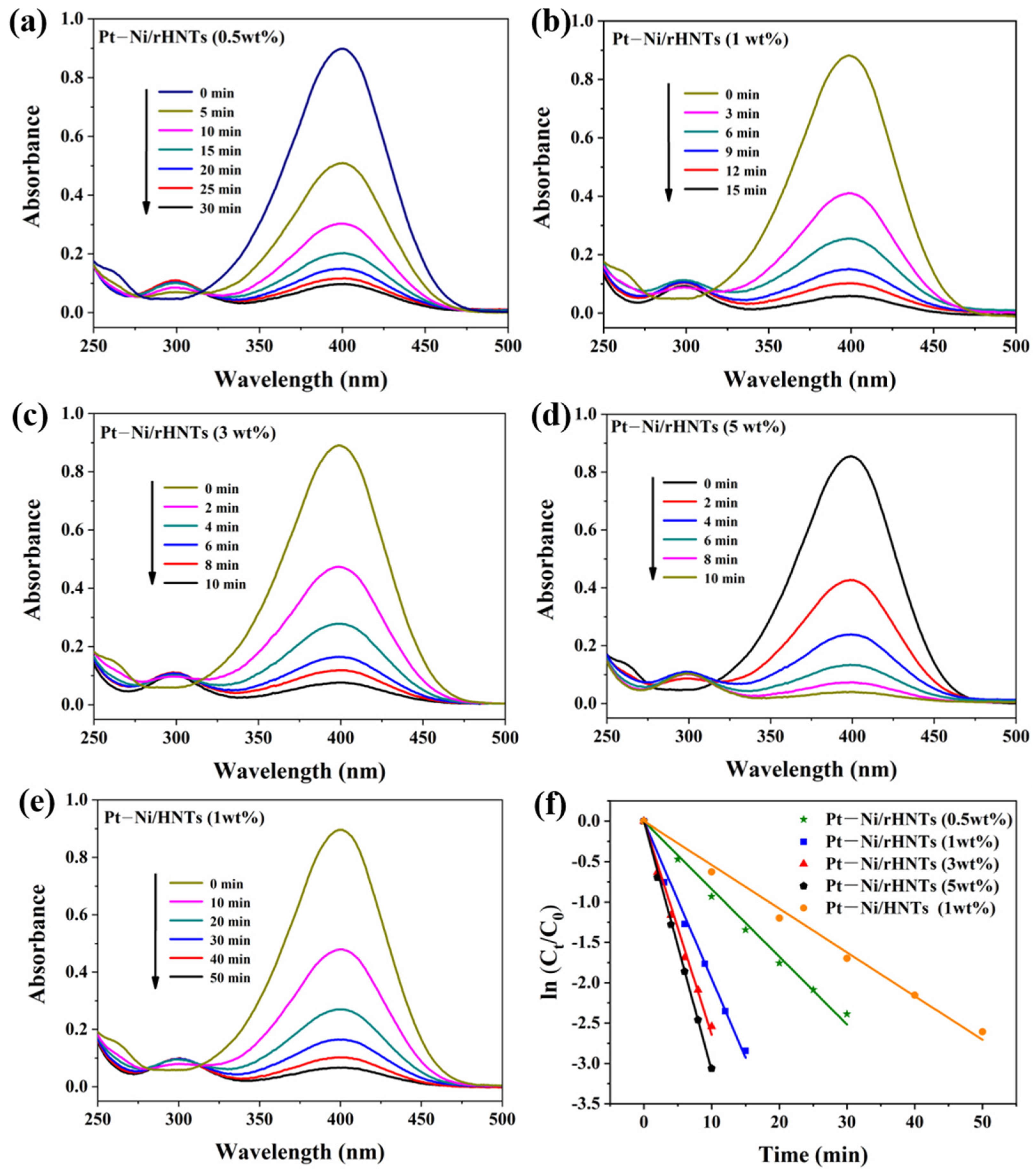
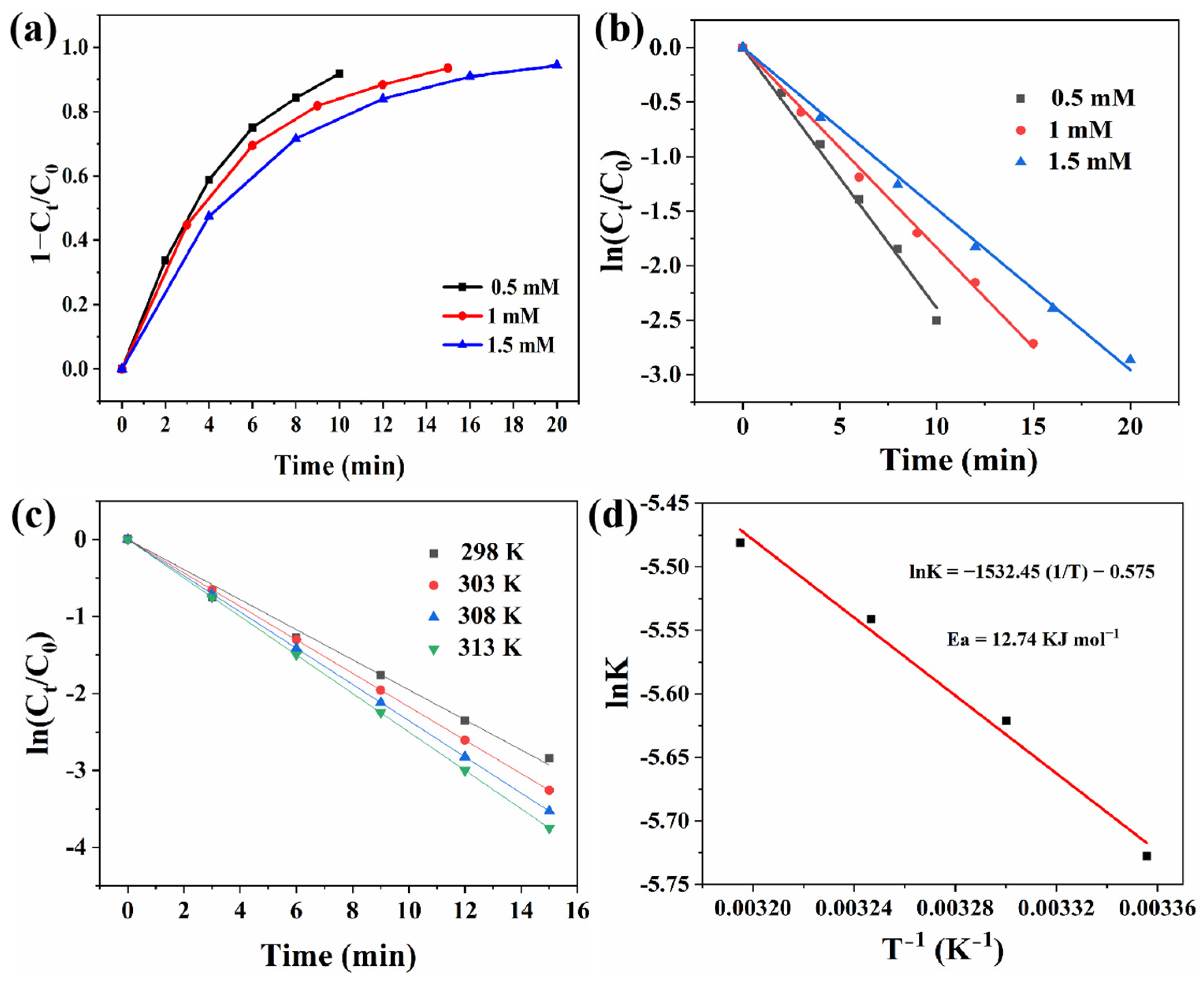
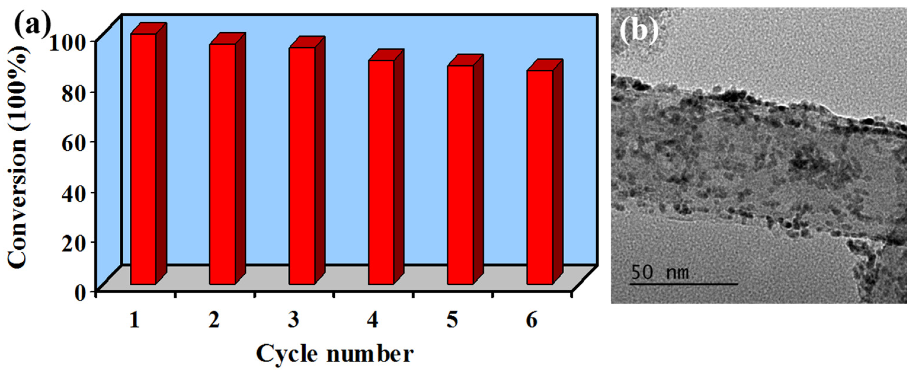
3.3. Catalytic Reduction of 4-NP on Pt–Ni/rHNT Nanocatalysts

The catalytic performance of Pt–Ni/rHNTs, Pt–Ni/HNTs and Pt/rHNTs was assessed by the hydrogenation reduction of 4-NP with NaBH4. Previous reports have shown that the kinetic hindrance between 4-NP and BH4 is very high and the catalytic reaction cannot proceed without a catalyst. When a catalyst is present, metal nanoparticles can serve as electron transfer mediators to transfer electrons from BH4 to the adsorbed 4-NP molecules on the catalyst surface [31]. The catalytic reaction process was monitored by a UV-Vis spectrophotometer, and the obtained UV absorbance spectrum changing with time was shown in Figure 6a–e and Figure S1. After adding NaBH4, the absorption peak of 4-NP shifts from 317 to 400 nm, which may result from the generated 4-NP ions [32]. The reaction starts immediately once the catalyst is added, and the peak intensity at 400 nm increasingly reduces with the continuous reduction of 4-NP, whereas a new peak at 300 nm is generated with an increasing intensity, suggesting that 4-NP is successfully reduced to 4-AP. As expected, Pt–Ni/rHNTs demonstrate a higher catalytic reaction rate as compared to Pt/rHNTs, indicating that the synergistic effect between Pt and Ni can reduce the reaction energy barrier, thus boosting the catalytic activity (Figure S1). Besides, it can be observed that the catalytic reaction times of Pt–Ni/rHNT nanocatalysts are all shorter than that of Pt–Ni/HNTs (1 wt %), indicating that the catalytic reaction rates of Pt–Ni/rHNTs are all higher than that of Pt–Ni/HNTs, which follow Pt–Ni/rHNTs (5 wt %) > Pt–Ni/rHNTs (3 wt %) > Pt–Ni/rHNTs (1 wt %) > Pt–Ni/rHNTs (0.5 wt %) > Pt–Ni/HNTs (1 wt %), indicating that the catalytic rates are highly dependent on the loading amount of metal particles, and molten salt etching of HNTs not only favors metal loading but also facilitates the diffusion and adsorption of reactants, thus increasing the catalytic activity.
Due to the involvement of excessive NaBH4, the reaction can be recognized as a first-order kinetics reaction. The rate constant (k) is calculated by Equation (1) to investigate the mechanism and further compare the catalytic performance [32,33],
k t = l n ( C t / C 0 ) = l n ( A t / A 0 )
in which C0 and Ct are the concentrations of 4-NP initially and at time t, respectively, and A0 and At are the UV-Vis absorption intensity at 400 nm at t = 0 and time t, respectively.
The relationship curves of ln(Ct/C0) versus t for all the samples are shown in Figure 6f. It is noted that all of them display straight lines with an R2 greater than 0.99, further testifying that the reaction conforms to the pseudo-first-order kinetic model. The k values of the as-prepared nanocatalysts were calculated and displayed in Table 2. Obviously, the k values of all of the Pt–Ni/rHNT nanocatalysts are greater than that of the Pt–Ni/HNTs, indicating that Pt–Ni/rHNTs have a better catalytic performance than Pt–Ni/HNTs. This may be because the rough surface of rHNTs can not only promote the adsorption of metal precursor ions, but also serves as the nucleation center of metal nanoparticles to promote their growth, so the rough surface of rHNTs is more favorable for the loading of Pt–Ni nanoparticles. Besides, the loading amount of metal particles has a great impact on the performance of the catalyst [34]. For Pt–Ni/rHNT nanocatalysts, the catalytic rate improves with the loading of Pt–Ni nanoparticles (from 0.5 to 5 wt %), because the larger the loading, the more exposed the active sites are in the catalytic reaction. During the catalytic reduction, BH4 will be absorbed on the catalyst’s surface, facilitating electron donation; the donated electrons are then transferred to the 4-NP adsorbed on the catalyst surface. In consequence, more loading of metal particles facilitates the delivery of electrons to the catalyst, and thus, better catalytic performance can be achieved [35]. Compared with similar catalysts in previous reports (Table S1), Pt–Ni/rHNTs (1 wt %) demonstrate a considerably high conversion rate, promising its potential application for 4-nitrophenol degradation.
Apart from k, turnover frequency (TOF) is another important parameter to evaluate the catalytic performance, which represents the conversion amount of reactant molecules for per gram of catalyst per second [26]. The TOF values of Pt–Ni/rHNT nanocatalysts increase first and reach a maximum plateau of 7.641 × 10¹⁹ molecules g−1 min−1 when the Pt–Ni loading amount is 1 wt %. The reason for the high TOF may be ascribed to the smallest particle size and the narrowest size distribution of Pt–Ni particles for Pt–Ni/rHNTs (1 wt %), as discussed for Figure 1. After that, the TOF values decline with increasing Pt–Ni loading amount, probably resulting from the increased particle size and agglomeration of nanoparticles, which is disadvantageous to the improvement of catalytic activity since catalysis only occurs on nanoparticle surfaces and larger particles usually present lower surface area and fewer active sites [26]. Therefore, reducing the size of Pt–Ni nanoparticles and increasing the dispersion can improve the catalytic efficiency of Pt–Ni/rHNTs. According to the above analysis, the active site density of Pt–Ni/rHNTs (0.5 wt %), Pt–Ni/rHNTs (3 wt %) and Pt–Ni/rHNTs (5 wt %) decrease due to the increase in particle size, so the TOF values are all smaller, although the reaction k are larger than those of Pt–Ni/rHNTs (1 wt %). Besides, Pt–Ni/HNTs have the smallest TOF compared to Pt–Ni/rHNTs, further indicating the favorable condition of rHNTs for metal loading.
The influence of the concentration of 4-NP and the temperature of the reaction on the catalytic reaction was investigated (Figure 7). As depicted in Figure 7a,b, it is noted that both the removal efficiency and the catalytic rates decrease with an increase in concentration of 4-NP from 0.5 mM to 1.5 mM, which may be attributed to the decreased effective collision and contact surface area, and the restricted diffusion and mass transfer between 4-NP molecules and the catalytic active sites on Pt–Ni/rHNTs. Such as it is, the 4-NP solution still can be completely degraded within 20 min on Pt–Ni/rHNTs, demonstrating its high catalytic degradation rate toward 4-NP solution As shown in Figure 7c, the catalytic rate can be increased with an increase in temperature, which can be due to the fact that the chance of collision between 4-NP and active sites is enhanced at higher temperatures. The apparent activation energy (Ea, J mol−1) can be deduced on the basis of the Arrhenius equation (Equation (2)), which is 12.74 kJ mol−1 by plot lnk versus 1/T (Figure 7d). The small Ea suggests that the degradation of 4-NP on Pt–Ni/r-HNTs takes place more easily.
l n k = E a R T + l n A ,
where k represents the catalytic rate (s−1), A signifies a constant related to reactant nature and reaction mechanism, R is 8.314 J mol−1 K−1 and T denotes the reaction temperature (K).
The reusability and stability of catalysts are important aspects for their practical application. To study the reusability of Pt–Ni/rHNTs, the used Pt–Ni/rHNTs were centrifugally separated, washed with ethanol and dried for another run. Since unavoidable loss of the used Pt–Ni/rHNTs exists during recycling, the added 4-NP was scaled down according to the actual amount of Pt–Ni/rHNTs by keeping the ratio of 4-NP and catalyst unchanged as the first run. In addition, the experiment was repeated for three times to obtain the average results to eliminate errors. As shown in Figure 8, the conversion efficiency of 4-NP slightly decreases but still maintains at a high level (about 85%) after six repetitions (Figure 8a). The slight decrease in catalytic performance was probably a result of the partial agglomeration of Pt–Ni nanoparticles, as evidenced in Figure 8b. These results reveal that the Pt–Ni/rHNT nanocatalyst has good reusability and stability, which shows its potential practical application in catalysis.
Based on our results and those of previous reports [36,37], the mechanism of the catalytic reduction of 4-NP on the Pt–Ni/rHNT catalyst can be put forward. Initially, both 4-NP and BH4 ions are absorbed on the surface of Pt–Ni/rHNTs, in which BH4 ions interact with the supported Pt–Ni nanoparticles to form a Pt–Ni-H complex. Next, the adsorbed BH4 ions transfer H• radicals and electrons to the absorbed 4-NP via the Pt–Ni nanoparticles, thus leading to the generation of 4-AP. Finally, the produced 4-AP releases from the Pt–Ni nanoparticles to the reaction solution. The porous structure of Pt–Ni/rHNTs makes the active sites readily accessible, which is tremendously beneficial for the rapid delivery of H• radicals and electrons, contributing to the increased catalytic reduction of 4-NP.

4. Conclusions

In conclusion, halloysite nanotubes (HNTs) with rough surfaces (rHNTs) were fabricated using the molten salt method, with sodium nitrate and sodium carbonate as the molten salt and etchant, respectively. The rough surface greatly improves the loading and dispersion of metal nanoparticles, which can consequently enhance the catalytic reduction of 4-NP. As a result, the as-prepared Pt–Ni/rHNT nanocatalysts exhibited distinguished catalytic performance for 4-NP reduction because of the ultrafine particle size, excellent dispersibility and synergy between Pt–Ni and the rHNTs. The optimized Pt–Ni/rHNTs (1 wt %) demonstrated the highest k of 0.1953 min−1, which exceeds other metal-based catalysts in previous reports. Besides, Pt–Ni/rHNTs (1 wt %) displayed outstanding stability and reusability. This work highlights the role of surface modification of HNTs for the loading of metal nanoparticles and provides an innovative idea for the preparation of low-cost catalysts.

Supplementary Materials

The following supporting information can be downloaded at: https://www.mdpi.com/article/10.3390/separations11110305/s1, Figure S1: UV–vis absorption spectra for Pt/rHNTs (1 wt %) and catalytic rate comparison of Pt/rHNTs (1 wt %) and Pt–Ni/rHNTs (1 wt %); Table S1: Comparison the k values of Pt–Ni/rHNTs with the similar catalysts in previous work.

Author Contributions

Conceptualization, Y.Z. and B.Z.; methodology, J.D. and Y.Z.; software, Z.Z.; validation, Z.Z. and S.C.; formal analysis, J.D.; investigation, S.C.; resources, B.Z.; data curation, J.D.; writing—original draft preparation, J.D.; writing—review and editing, Y.Z. and S.C.; visualization, Z.Z.; supervision, Y.Z.; project administration, B.Z. and S.C.; funding acquisition, B.Z., S.C. and Y.Z. All authors have read and agreed to the published version of the manuscript.

Funding

This research was funded by the National Natural Science Foundation of China (Grant Nos. U22A20143 and U20041100), Joint Fund of Henan Province Science and Technology R&D Program (Grant Nos. 225200810056 and 235200810044) and Education and Teaching Reform Research and Practice Project of Zhengzhou University (2023ZZUJGXM208).

Data Availability Statement

The data presented in this study are available on request from the corresponding author due to privacy.

Conflicts of Interest

The authors declare no conflicts of interest.

References

  1. Li, Y.; Quan, X.; Hu, C.; Li, C. Effective catalytic reduction of 4-nitrophenol to 4-aminophenol over etched halloysite nanotubes@α-Ni(OH)2. ACS Appl. Energy Mater. 2020, 3, 4756–4766. [Google Scholar] [CrossRef]
  2. Cheng, H.; Yang, Z.; Du, F.; Liu, H.; Zhang, Q.; Zhang, Y. Recyclable Ag/halloysite nanotubes/polyvinyl alcohol sponges for enhanced reduction of 4-nitrophenol. Appl. Clay Sci. 2022, 223, 106510. [Google Scholar] [CrossRef]
  3. Wi-Afedzi, T.; Kwon, E.; Tuan, D.D.; Lin, K.A.; Ghanbari, F. Copper hexacyanoferrate nanocrystal as a highly efficient non-noble metal catalyst for reduction of 4-nitrophenol in water. Sci. Total Environ. 2020, 703, 134781. [Google Scholar] [CrossRef]
  4. Zhang, M.; Su, X.; Ma, L.; Khan, A.; Wang, L.; Wang, J.; Maloletnev, A.S.; Yang, C. Promotion effects of halloysite nanotubes on catalytic activity of Co3O4 nanoparticles toward reduction of 4-nitrophenol and organic dyes. J. Hazard. Mater. 2021, 403, 123870. [Google Scholar] [CrossRef]
  5. Yu, J.; Niedenthal, W.; Smarsly, B.M.; Natile, M.M.; Huang, Y.; Carraro, M. Au nanoparticles supported on piranha etched halloysite nanotubes for highly efficient heterogeneous catalysis. Appl. Surf. Sci. 2021, 546, 149100. [Google Scholar] [CrossRef]
  6. Hu, R.; Xu, R.; Wang, Z.; Wang, J.; Zhou, S. Enhanced catalytic nitrophenol reduction via highly porous hollow silica nanospheres stabilized Au nanoclusters. Chem. Eng. J. 2023, 471, 144780. [Google Scholar] [CrossRef]
  7. Zhang, L.; Zhang, J.; Tan, W.; Zhong, C.; Tu, Y.; Song, H.; Du, L.; Liao, S.; Cui, Z. Amorphous TiOx stabilized intermetallic Pt3Ti nanocatalyst for methanol oxidation reaction. Nano Lett. 2023, 23, 5187–5193. [Google Scholar] [CrossRef]
  8. Nugraha, A.S.; Na, J.; Hossain, M.S.A.; Lin, J.; Kaneti, Y.V.; Iqbal, M.; Jiang, B.; Bando, Y.; Asahi, T.; Yamauchi, Y. Block copolymer-templated electrodeposition of mesoporous Au-Ni alloy films with tunable composition. Appl. Mater. Today 2020, 18, 100526. [Google Scholar] [CrossRef]
  9. Swain, S.; Kandathil, V.; Karim, G.M.; Maiti, U.N.; Patil, S.A.; Samal, A.K. Computational and experimental design of the octahedral PdFe alloy nanocatalyst for hiyama cross-coupling and environmental pollutant degradation. ACS Appl. Nano Mater. 2023, 6, 3254–3267. [Google Scholar] [CrossRef]
  10. Wang, L.; Zhao, Y.; Chen, H.; Yang, Y.; Wang, D.; Shang, H.; Zhang, B. Phosphorus and sulfur co-doped nickel molybdate with rich-oxygen vacancies for efficient water splitting. J. Colloid Interface Sci. 2025, 677, 167–177. [Google Scholar] [CrossRef]
  11. Yang, Y.; Zhang, L.; Gao, X.; Zhao, Y. Constructing ultrafine monodispersed Co2P/(0.59-Cu3P) on Cu doped CoZn-ZIF derived porous N-doped carbon for highly efficient dehydrogenation of ammonia borane. Nano Res. 2023, 16, 6687–6700. [Google Scholar] [CrossRef]
  12. Wang, L.; Wang, P.; Xue, X.; Wang, D.; Shang, H.; Zhao, Y.; Zhang, B. Interface engineering of three-phase nickel–cobalt sulfide/nickel phosphide/iron phosphide heterostructure for enhanced water splitting and urea electrolysis. J. Colloid Interface Sci. 2024, 665, 88–99. [Google Scholar] [CrossRef] [PubMed]
  13. Orfei, E.; Fasolini, A.; Abate, S.; Dimitratos, N.; Basile, F. Layered-double hydroxides and derived oxide as CRM-free highly active catalysts for the reduction of 4-nitrophenol. Catal. Today 2023, 419, 114153. [Google Scholar] [CrossRef]
  14. Xiong, C.; Zhang, X.; Lei, Y.; Zhang, L.; Shang, H.; Zhang, B.; Zhao, Y. One-pot synthesis of ultrafine Ni0.13Co0.87P nanoparticles on halloysite nanotubes as efficient catalyst for hydrogen evolution from ammonia borane. Appl. Clay Sci. 2021, 214, 106293. [Google Scholar] [CrossRef]
  15. Zhao, Y.; Kong, W.; Jin, Z.; Fu, Y.; Wang, W.; Zhang, Y.; Liu, J.; Zhang, B. Storing solar energy within Ag-paraffin@halloysite microspheres as a novel self-heating catalyst. Appl. Energy 2018, 222, 180–188. [Google Scholar] [CrossRef]
  16. Wang, Q.; Wang, Y.; Zhao, Y.; Zhang, B.; Niu, Y.; Xiang, X.; Chen, R. Fabricating roughened surfaces on halloysite nanotubes via alkali etching for deposition of high-efficiency Pt nanocatalysts. CrystEngComm 2015, 17, 3110. [Google Scholar] [CrossRef]
  17. Ma, X.; Yang, C.; Feng, X.; Shang, H.; Zhao, Y.; Zhang, B. Halloysite-based aerogels for efficient encapsulation of phase change materials with excellent solar energy storage and retrieval performance. Appl. Energy 2023, 341, 121101. [Google Scholar] [CrossRef]
  18. Lvov, Y.; Wang, W.; Zhang, L.; Fakhrullin, R. Halloysite clay nanotubes for loading and sustained release of functional compounds. Adv. Mater. 2016, 28, 1227–1250. [Google Scholar] [CrossRef]
  19. Zhao, Y.; Guo, S.; Xue, X.; Xiong, C.; Gao, X.; Zhang, B. Halloysite nanotubes supported Co2P bridged by carbon dots for enhanced hydrogen evolution from ammonia borane. Chem. Eng. J. 2024, 483, 149332. [Google Scholar] [CrossRef]
  20. Yuan, P.; Tan, D.; Annabi-Bergaya, F. Properties and applications of halloysite nanotubes: Recent research advances and future prospects. Appl. Clay Sci. 2015, 112–113, 75–93. [Google Scholar] [CrossRef]
  21. Guo, L.; Mi, A.; Xue, X.; Wu, Z.; Gao, H.; Shang, H.; Wang, D.; Zhao, Y.; Zhang, B. Enhanced hydrophilicity and stability of carbon-based aerogel with assembling of halloysite nanotubes and silica fibers for efficient solar seawater evaporation and desalination. Sep. Purif. Technol. 2024, 342, 126966. [Google Scholar] [CrossRef]
  22. Mi, A.; Guo, L.; Yan, Y.; Wang, D.; Shang, H.; Zhao, Y.; Zhang, B. A solid-system strategy for controlled hydrolytic release of hydrogen by encapsulation of ammonia borane in cobalt decorated halloysite aerogel. ACS Sustain. Chem. Eng. 2024, 12, 5716–5725. [Google Scholar] [CrossRef]
  23. Chen, P.; Tang, Y.; Gao, Y.; Zhang, Y.; Liu, L. Design and structure optimization of coal-based hierarchical porous carbon by molten salt method for high-performance supercapacitors. J. Power Sources 2023, 580, 233334. [Google Scholar] [CrossRef]
  24. Arole, K.; Blivin, J.W.; Saha, S.; Holta, D.E.; Zhao, X.; Sarmah, A.; Cao, H.; Radovic, M.; Lutkenhaus, J.L.; Green, M.J. Water-dispersible Ti3C2Tz MXene nanosheets by molten salt etching. iScience 2021, 24, 103403. [Google Scholar] [CrossRef]
  25. Sun, G.; Liu, Y.; Dong, S.; Wang, J. Study on novel molten salt-ceramics composite as energy storage material. J. Energy Storage 2020, 28, 101237. [Google Scholar] [CrossRef]
  26. Zhao, F.; Kong, W.; Hu, Z.; Liu, J.; Zhao, Y.; Zhang, B. Tuning the performance of Pt–Ni alloy/reduced graphene oxide catalysts for 4-nitrophenol reduction. RSC Adv. 2016, 6, 79028–79036. [Google Scholar] [CrossRef]
  27. Wang, Y.; He, W.; Wang, L.; Yang, J.; Xiang, X.; Zhang, B.; Li, F. Highly active supported Pt nanocatalysts synthesized by alcohol reduction towards hydrogenation of cinnamaldehyde: Synergy of metal valence and hydroxyl groups. Chem. Asian J. 2015, 10, 1561–1570. [Google Scholar] [CrossRef]
  28. Yang, X.; Wang, J.; Wei, Y.; Li, B.; Yan, W.; Yin, L.; Wu, D.; Liu, P.; Zhang, P. Cotton-derived carbon fiber-supported Ni nanoparticles as nanoislands to anchor single-atom Pt for efficient catalytic reduction of 4-nitrophenol. Appl. Catal. A General 2022, 643, 118734. [Google Scholar] [CrossRef]
  29. Zhao, H.; Pang, X.; Huang, Y.; Bai, Y.; Ding, J.; Bai, H.; Fan, W. Ag/Ni–MOF heterostructure with synergistic enrichment and activation properties for electrocatalytic reduction of 4-nitrophenol. Chem. Commun. 2022, 58, 13499–13502. [Google Scholar] [CrossRef]
  30. Zhao, L.; Wei, Q.; Zhang, L.; Zhao, Y.; Zhang, B. NiCo alloy decorated on porous N-doped carbon derived from ZnCoZIF as highly efficient and magnetically recyclable catalyst for hydrogen evolution from ammonia borane. Renew. Energy 2021, 173, 273–282. [Google Scholar] [CrossRef]
  31. Chen, X.; Cai, Z.; Chen, X.; Oyama, M. AuPd bimetallic nanoparticles decorated on graphene nanosheets: Their green synthesis, growth mechanism and high catalytic ability in 4-nitrophenol reduction. J. Mater. Chem. A 2014, 2, 5668–5674. [Google Scholar] [CrossRef]
  32. Wang, X.; Tan, F.; Wang, W.; Qiao, X.; Qiu, X.; Chen, J. Anchoring of silver nanoparticles on graphitic carbon nitride sheets for the synergistic catalytic reduction of 4-nitrophenol. Chemosphere 2017, 172, 147–154. [Google Scholar] [CrossRef] [PubMed]
  33. Shi, J.; Zhang, L.; Shen, Q.; Sun, N.; Wei, W. Surfactant-free synthesis of Ag nanoparticles loaded ZIF-8 as a catalytic filter device for continuous reduction of 4-nitrophenol. Catal. Lett. 2023, 153, 453–459. [Google Scholar] [CrossRef]
  34. Su, D.S.; Perathoner, S.; Centi, G. Nanocarbons for the development of advanced catalysts. Chem. Rev. 2013, 113, 5782–5816. [Google Scholar] [CrossRef]
  35. Nguyen, T.B.; Huang, C.P.; Doong, R. Enhanced catalytic reduction of nitrophenols by sodium borohydride over highly recyclable Au@graphitic carbon nitride nanocomposites. Appl. Catal. B Environ. 2019, 240, 337–347. [Google Scholar] [CrossRef]
  36. Dai, Y.; Chen, Y.; Zhu, W.; Lin, Z.; Tsai, M. In-situ fabrication of Ag nanoparticles decorated magnetic N-doped graphene heterogeneous catalyst for the catalytic reduction of 4-nitrophenol. J. Taiwan Inst. Chem. Eng. 2024, 163, 105524. [Google Scholar] [CrossRef]
  37. Chen, Y.; Shi, W.; Yeh, J.; Tsai, M. In-situ synthesis of Au/carbonized botanical leaf functionalized-electroactive polyimide nanocomposites and their application in enhanced catalytic activity for reduction 4-nitrophenol. J. Environ. Chem. Eng. 2024, 12, 111455. [Google Scholar] [CrossRef]
Figure 1. Schematic illustration of the synthesis of Pt–Ni/rHNTs.
Separations 11 00305 g001
Figure 2. TEM images of (a) Pt–Ni/HNTs (1 wt %) (inset is the HRTEM image), (b) Pt–Ni/rHNTs (0.5 wt %), (c) Pt–Ni/rHNTs (1 wt %) and (d) Pt–Ni/rHNTs (3 wt %) (insets are the corresponding size distribution).
Separations 11 00305 g002
Figure 3. AFM images of (a) HNTs and (b) rHNTs.
Separations 11 00305 g003
Figure 4. (a) BET and (b) pore size distribution of rHNTs and Pt–Ni/rHNTs. XRD patterns of (c) HNTs and rHNTs, (d) Pt–Ni/HNTs (1 wt %) and Pt–Ni/rHNT nanocatalysts with different loading contents (0.5, 1, 3, 5 wt %) from the bottom to the top.
Separations 11 00305 g004
Figure 5. XPS (a) survey spectrum of Pt–Ni/rHNTs (1 wt %), (b) Pt 4f spectrum of Pt–Ni/rHNTs, (c) Pt 4f spectrum of Pt/rHNTs and (d) Ni 2p spectrum of Pt–Ni/ rHNTs (1 wt %).
Separations 11 00305 g005
Figure 6. Time-dependent UV-Vis absorption spectra of 4-NP by NaBH4 catalyzed by (a) Pt–Ni/rHNTs (0.5 wt %), (b) Pt–Ni/rHNTs (1 wt %), (c) Pt–Ni/rHNTs (3 wt %), (d) Pt–Ni/rHNTs (5 wt %) and (e) Pt–Ni/HNTs (1 wt %). (f) Plot of ln (Ct/C0) versus time of the reduction of 4-NP.
Separations 11 00305 g006
Figure 7. The plots of (a) removal efficiency and (b) ln (Ct/C0) versus time of the reduction of 4-NP with different concentration on Pt–Ni/rHNTs. (c) The plots ln (Ct/C0) versus time of the reduction of 4-NP under different temperature on Pt–Ni/rHNTs. (d) The Arrhenius plot of 4-NP reduction on Pt–Ni/rHNTs.
Separations 11 00305 g007
Figure 8. (a) The reusability of the Pt–Ni/rHNT (1 wt %) nanocatalyst for the catalytic reduction of 4-NP, and (b) TEM image of Pt–Ni/rHNTs (1 wt %) after cycling.
Separations 11 00305 g008
Table 1. Actual loading of Pt–Ni determined from ICP-MS.
CatalystsPt–Ni/rHNTsPt–Ni/HNTs
Theoretical Pt–Ni loading (wt %)0.51351
Measured actual Pt–Ni loading (wt %)0.360.802.634.100.32
Table 2. Comparison the catalytic rate, R2 and TOF of different catalysts.
SampleK (min−1)R2TOF (×1017) Molecules g−1 s−1
Pt–Ni/rHNTs (0.5 wt %)0.08410.9902611.2
Pt–Ni/rHNTs (1 wt %)0.19530.9915764.1
Pt–Ni/rHNTs (3 wt %)0.26450.9903317.3
Pt–Ni/rHNTs (5 wt %)0.30880.9986240.8
Pt–Ni/HNTs (1 wt %)0.05410.9923187.7
Disclaimer/Publisher’s Note: The statements, opinions and data contained in all publications are solely those of the individual author(s) and contributor(s) and not of MDPI and/or the editor(s). MDPI and/or the editor(s) disclaim responsibility for any injury to people or property resulting from any ideas, methods, instructions or products referred to in the content.

