
Numerical Study on Heat Transfer Efficiency of Regenerative Thermal Oxidizers with Three Canisters

Abstract
:1. Introduction
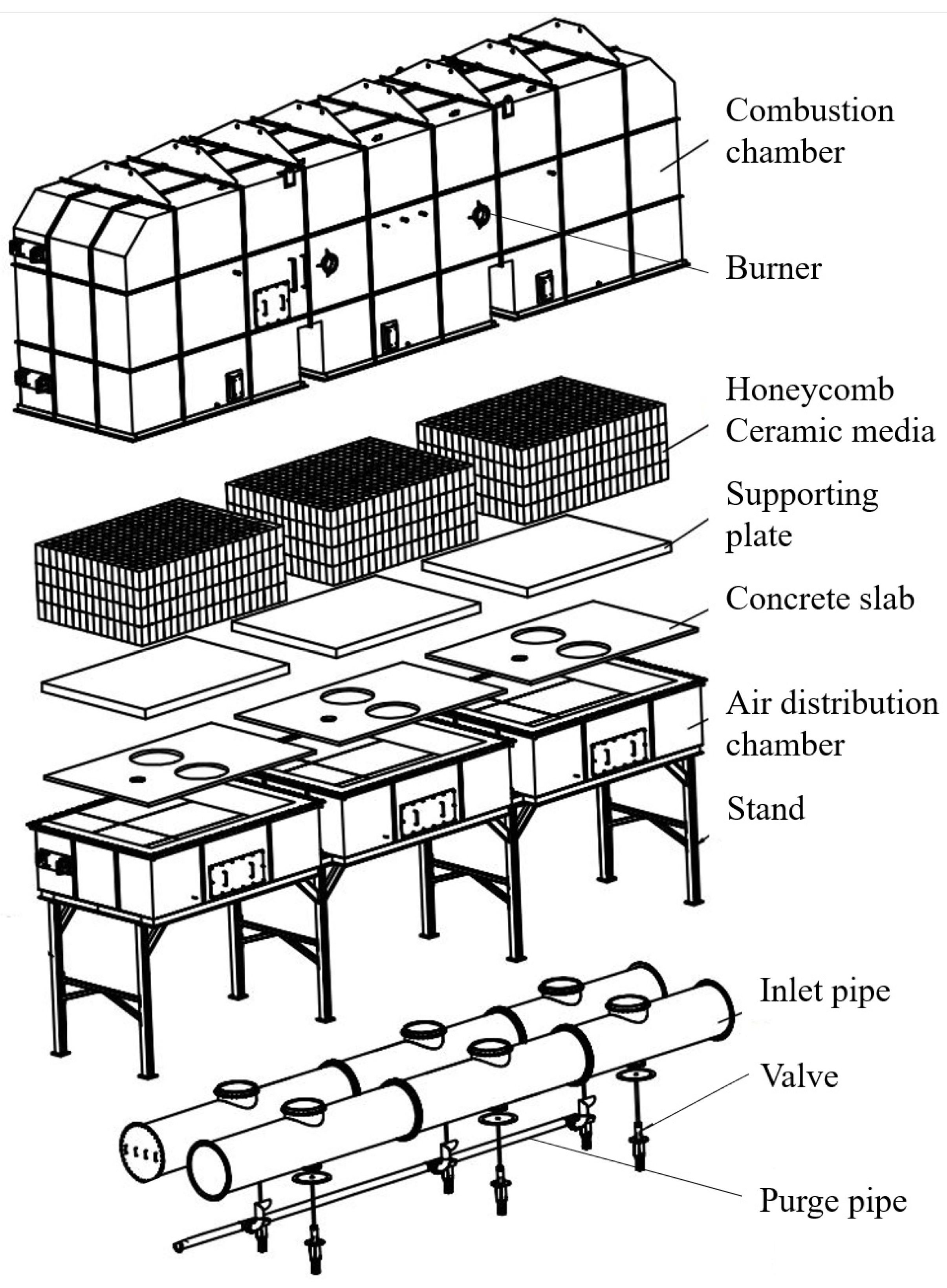
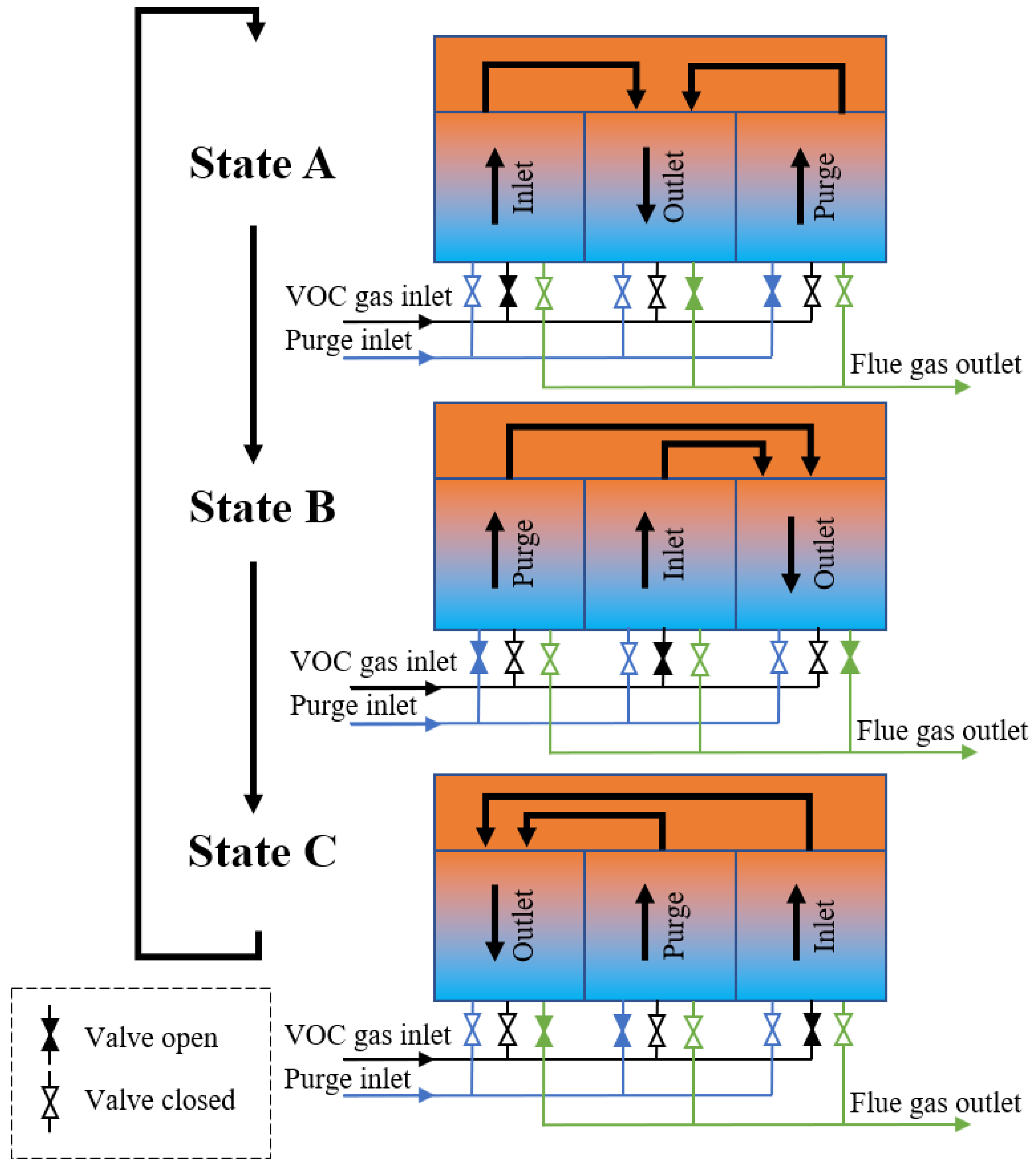
2. Physical Model
3. Numerical Methods
3.1. Governing Equations
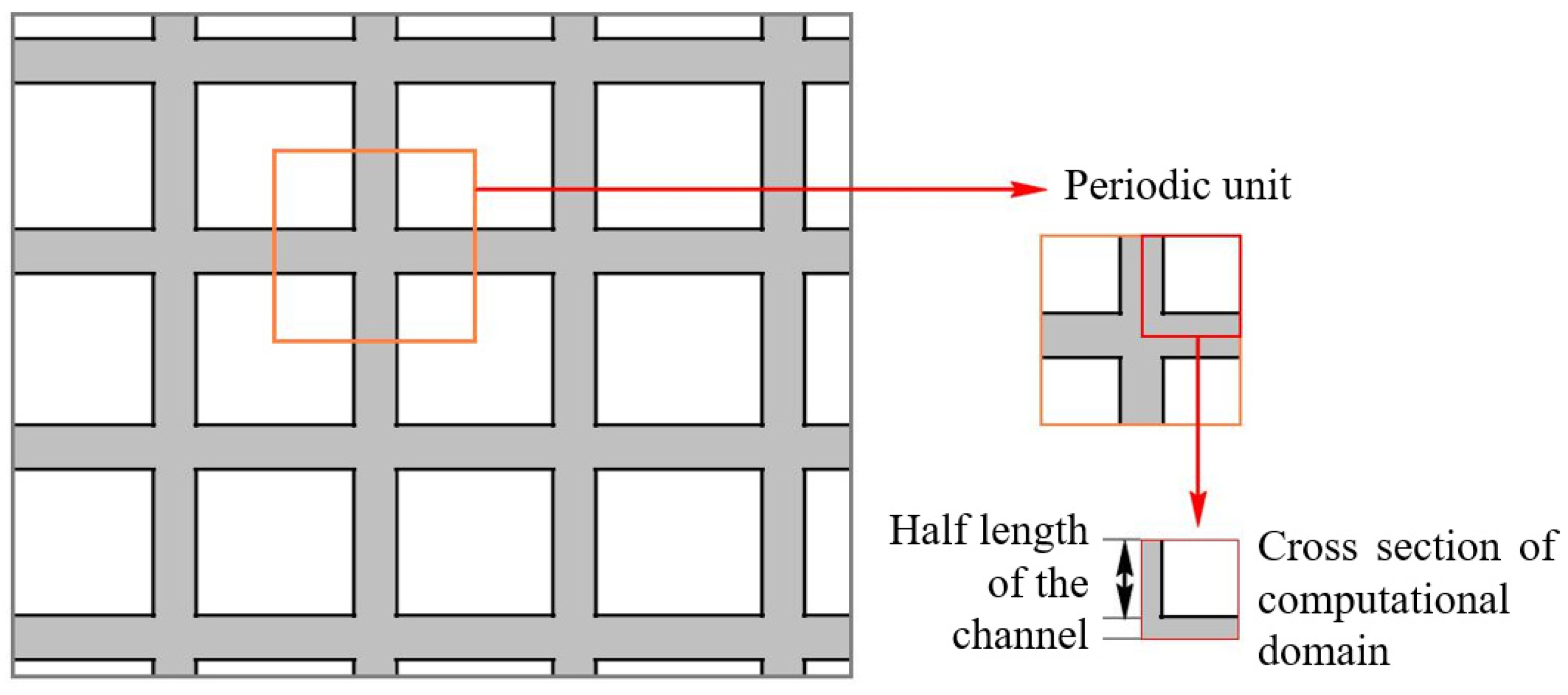
3.2. Computation Domain and Mesh Generation
3.3. Parameters and Physical Models
3.4. Initial and Boundary Conditions
3.5. Discrete Scheme and Algorithm
4. Results and Discussion
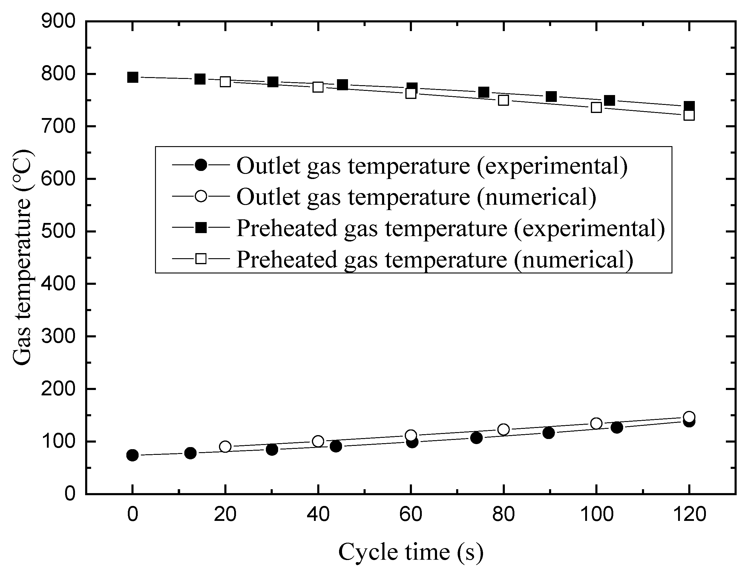
4.1. Calculation Verification
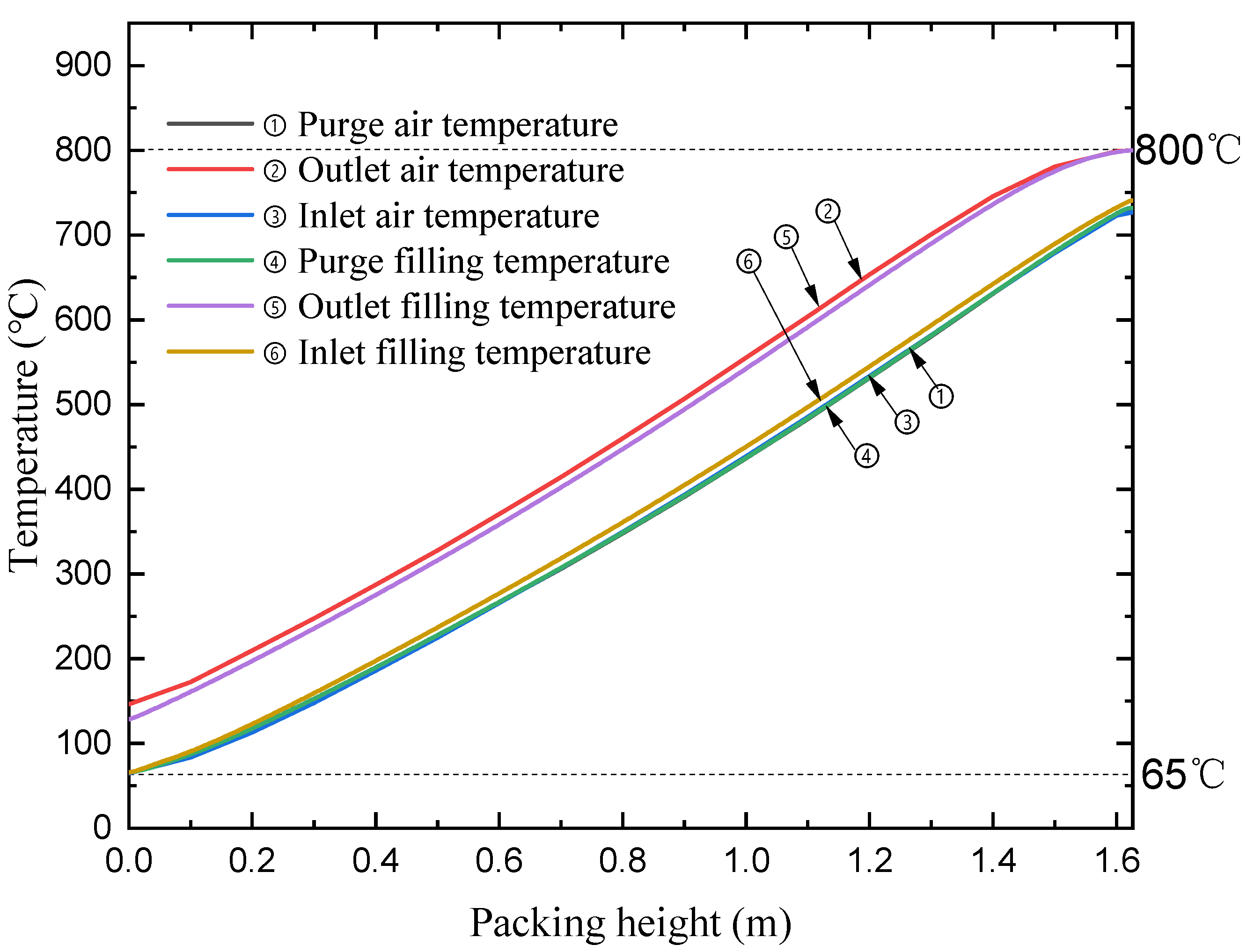
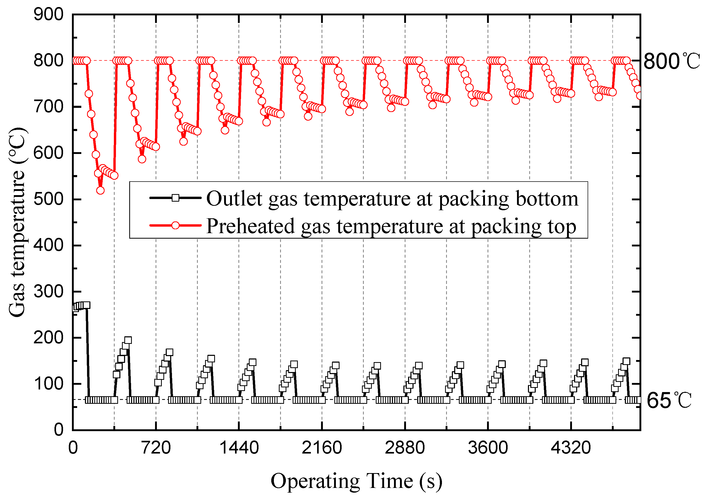
4.2. Temperature Distribution along with the Canister Height
4.3. Thermal Efficiencies
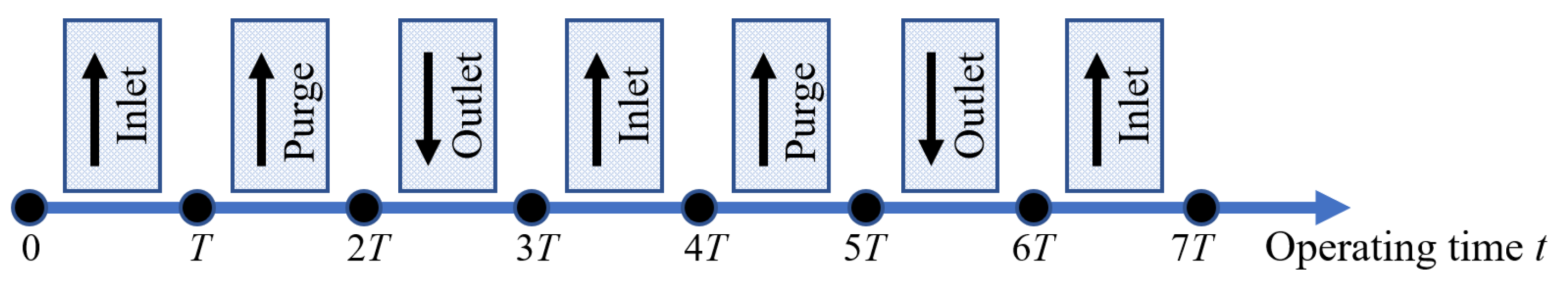
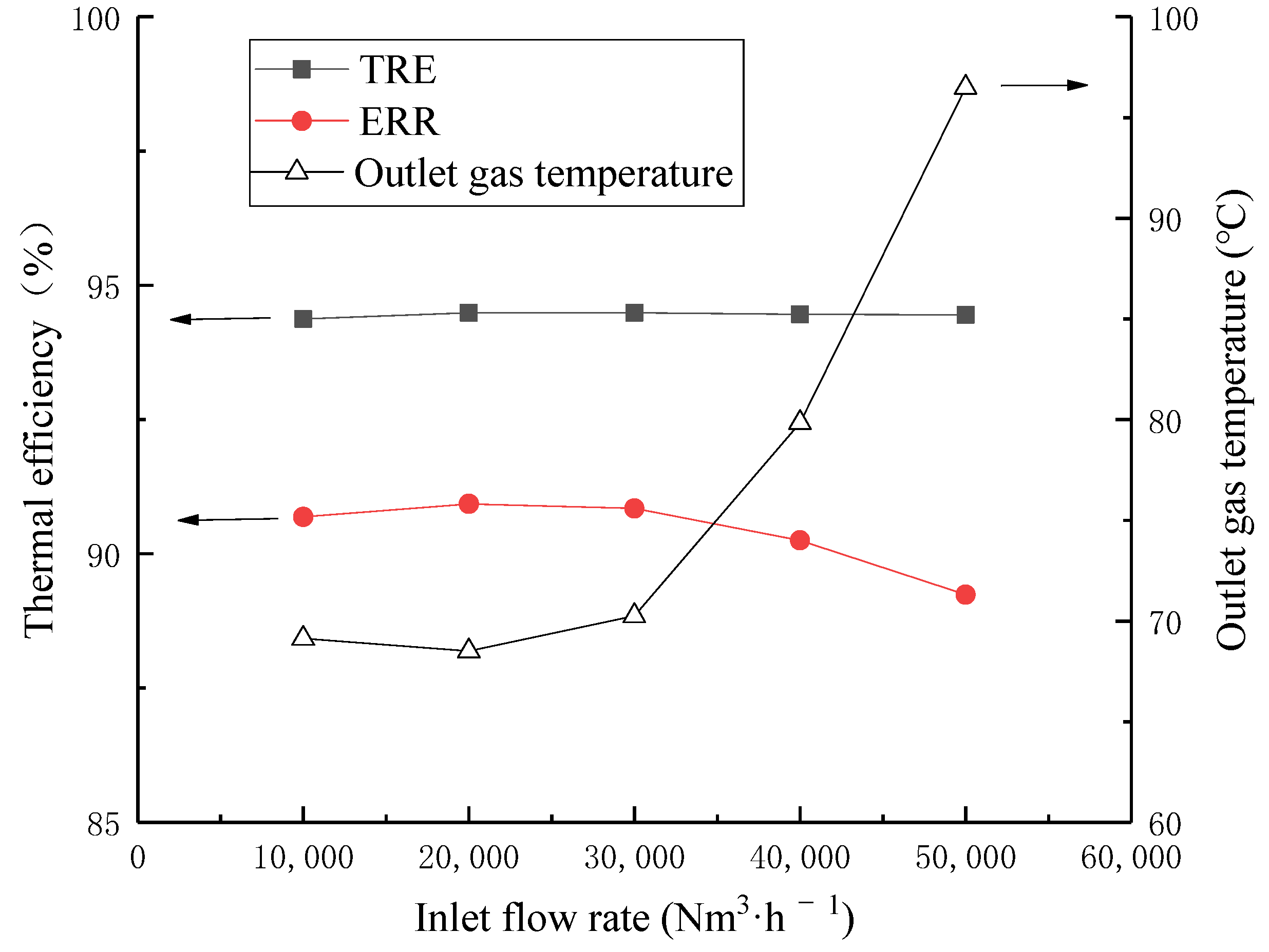
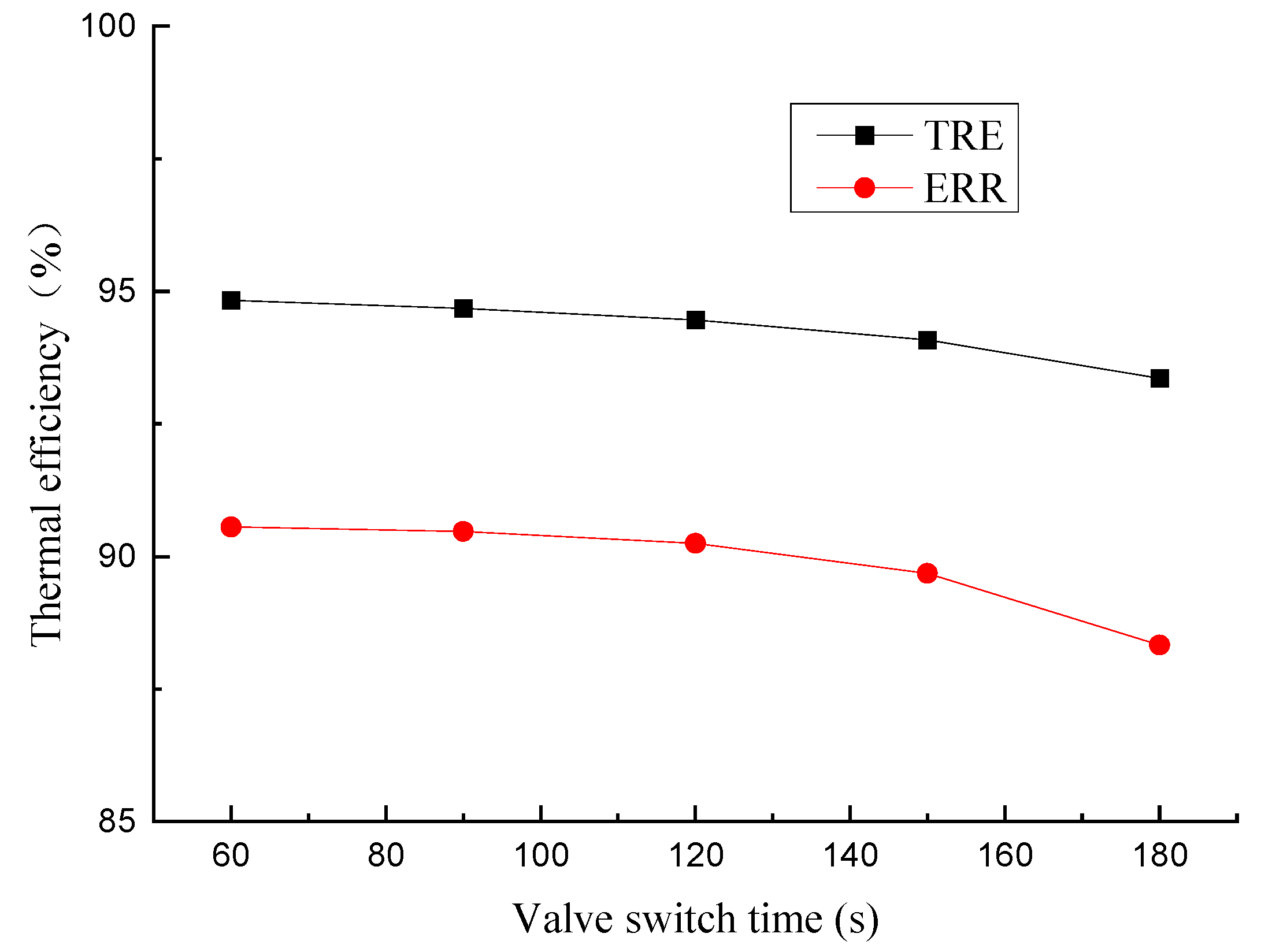
4.3.1. Effect of Inlet Flow Rate and Valve Switch Time
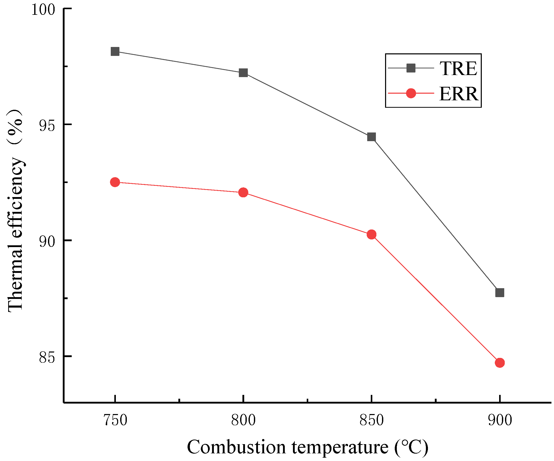
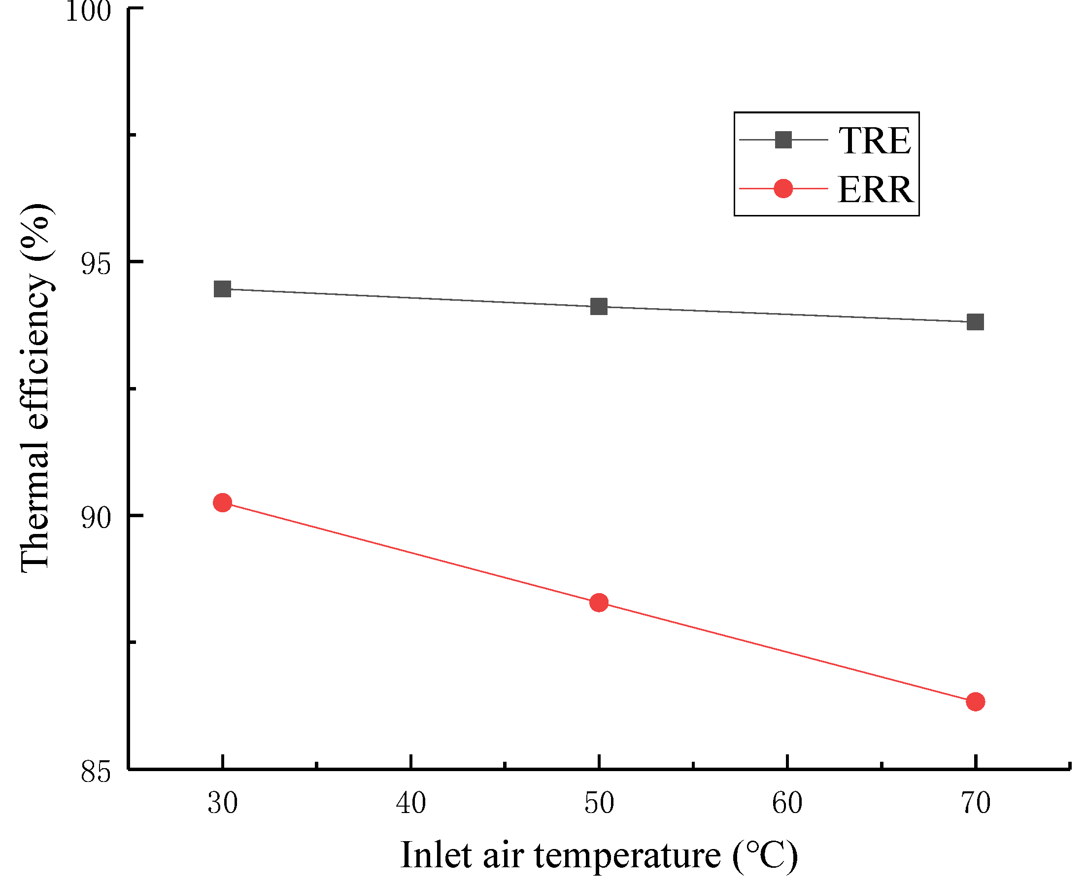
4.3.2. Effect of Inlet Air Temperature and Combustion Temperature
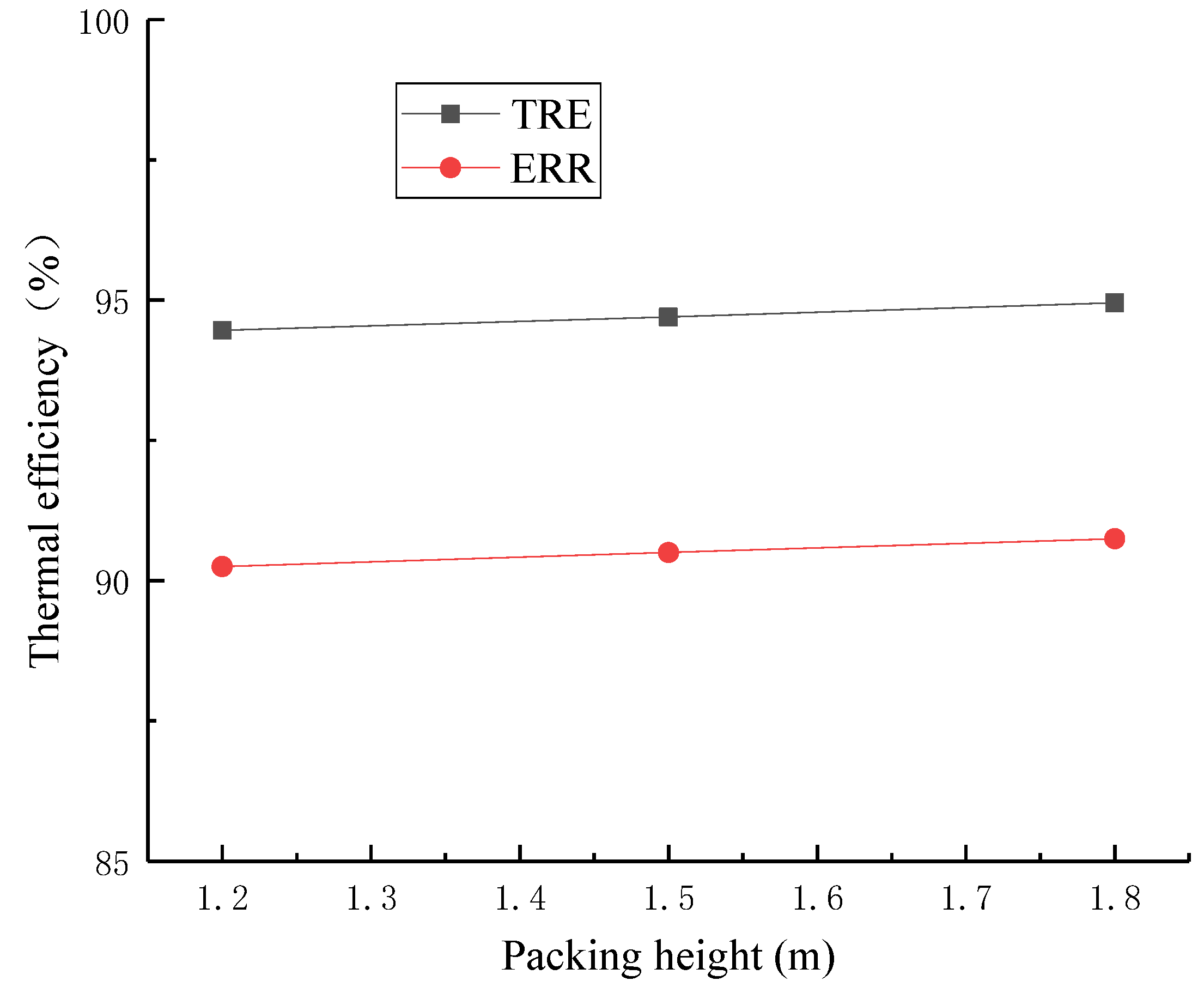
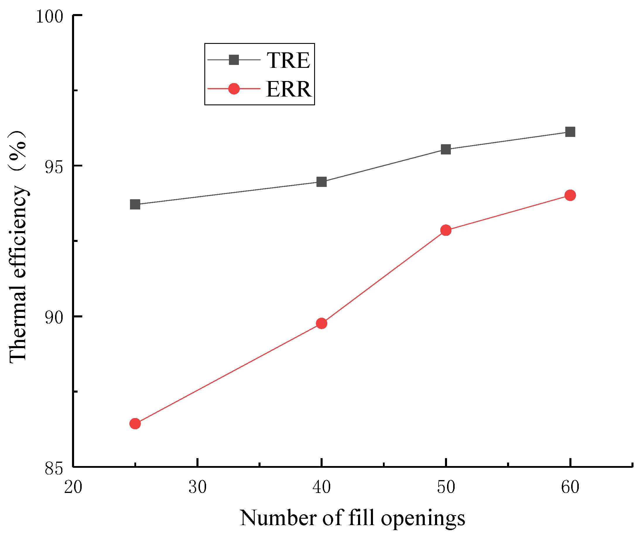
4.3.3. Effect of Regenerative Media Porosity and Packing Height
4.3.4. Effect of Regenerative Media Materials and the VOC Concentration
5. Conclusions
Author Contributions
Funding
Institutional Review Board Statement
Informed Consent Statement
Data Availability Statement
Acknowledgments
Conflicts of Interest
References
- Tsuji, H.; Gupta, A.K.; Hasegawa, T.; Katsuki, M.; Kishimoto, K.; Morita, M. High Temperature Air Combustion: From Energy Conservation to Pollution Reduction; CRC Press: Boca Raton, FL, USA, 2002. [Google Scholar]
- Lewandowski, D.A. Design of Thermal Oxidation Systems for Volatile Organic Compounds; CRC Press: Boca Raton, FL, USA, 2017; pp. 157–168. [Google Scholar]
- Hao, X.; Li, R.; Wang, J.; Yang, X. Numerical simulation of a regenerative thermal oxidizer for volatile organic compounds treatment. Environ. Eng. Res. 2018, 23, 397–405. [Google Scholar] [CrossRef] [Green Version]
- Giuntini, L.; Bertei, A.; Tortorelli, S.; Percivale, M.; Paoletti, E.; Nicolella, C.; Galletti, C. Coupled CFD and 1-D dynamic modeling for the analysis of industrial Regenerative Thermal Oxidizers. Chem. Eng. Process. 2020, 157, 108117. [Google Scholar] [CrossRef]
- Kang, K.; Hong, S.-K.; Noh, D.-S.; Ryou, H.-S. Heat transfer characteristics of a ceramic honeycomb regenerator for an oxy-fuel combustion furnace. Appl. Therm. Eng. 2014, 70, 494–500. [Google Scholar] [CrossRef]
- Hong, S.K.; Noh, D.S.; Lee, E.k. Improvement in thermal efficiency of regenerator system by using oxy-fuel combustion. Appl. Therm. Eng. 2015, 87, 648–654. [Google Scholar] [CrossRef]
- Gosiewski, K.; Pawlaczyk, A.; Jaschik, M. Energy recovery from ventilation air methane via reverse-flow reactors. Energy 2015, 92, 13–23. [Google Scholar] [CrossRef]
- Gosiewski, K.; Pawlaczyk-Kurek, A. Aerodynamic CFD simulations of experimental and industrial thermal flow reversal reactors. Chem. Eng. J. 2019, 373, 1367–1379. [Google Scholar] [CrossRef]
- Lin, C.-N.; Jang, J.-Y.; Lai, Y.-S. Two dimensional thermal-hydraulic analysis for a packed bed regenerator used in a reheating furnace. Energies 2016, 9, 995. [Google Scholar] [CrossRef] [Green Version]
- Marín, P.; Díez, F.V.; Ordóñez, S. A new method for controlling the ignition state of a regenerative combustor using a heat storage device. Appl. Energy 2014, 116, 322–332. [Google Scholar] [CrossRef] [Green Version]
- Marín, P.; Vega, A.; Díez, F.V.; Ordóñez, S. Control of regenerative catalytic oxidizers used in coal mine ventilation air methane exploitation. Process Saf. Environ. Prot. 2020, 134, 333–342. [Google Scholar] [CrossRef]
- You, Y.; Huang, H.; Shao, G.; Hu, J.; Xu, X.; Luo, X. A three-dimensional numerical model of unsteady flow and heat transfer in ceramic honeycomb regenerator. Appl. Therm. Eng. 2016, 108, 1243–1250. [Google Scholar] [CrossRef]
- You, Y.; Wu, Z.; Li, B.; Zhang, Z.; Pan, S.; Xu, X. 3D numerical simulation and optimization of honeycomb regenerators with parallel or crosswise arrangement of circular holes. Chem. Eng. Process. 2019, 137, 22–27. [Google Scholar] [CrossRef]
- Yuan, F.; Wang, H.; Zhou, P.; Xu, A.; He, D. Heat transfer performances of honeycomb regenerators with square or hexagon cell opening. Appl. Therm. Eng. 2017, 125, 790–798. [Google Scholar] [CrossRef]
- Alfarawi, S.; Al-Dadah, R.; Mahmoud, S. Transient investigation of mini-channel regenerative heat exchangers: Combined experimental and CFD approach. Appl. Therm. Eng. 2017, 125, 346–358. [Google Scholar] [CrossRef] [Green Version]
- Lan, B.; Li, Y.-R. Numerical study on thermal oxidation of lean coal mine methane in a thermal flow-reversal reactor. Chem. Eng. J. 2018, 351, 922–929. [Google Scholar] [CrossRef]
- Wang, F.; Lei, X.; Hao, X. Key factors in the volatile organic compounds treatment by regenerative thermal oxidizer. J. Air Waste Manag. Assoc. 2020, 70, 557–567. [Google Scholar] [CrossRef] [PubMed]
- Gao, P.-F.; Gou, X.-L. Experimental research on the thermal oxidation of ventilation air methane in a thermal reverse flow reactor. ACS Omega 2019, 4, 14886–14894. [Google Scholar] [CrossRef] [PubMed]
- Singh, G.; Kumar, G.; Murthy, D.S. Wavelet based simulation of thermal regenerator. Therm. Sci. Eng. Prog. 2019, 9, 142–147. [Google Scholar] [CrossRef]
- Kumar, G.; Murthy, D.S. A multiresolution wavelet optimised finite-difference method for simulation of thermal regenerator. Therm. Sci. Eng. Prog. 2020, 19, 100669. [Google Scholar] [CrossRef]
- You, Y.; Fan, A.; Lai, X.; Huang, S.; Liu, W. Experimental and numerical investigations of shell-side thermo-hydraulic performances for shell-and-tube heat exchanger with trefoil-hole baffles. Appl. Therm. Eng. 2013, 50, 950–956. [Google Scholar] [CrossRef]
- You, Y.; Wu, Z.; Zeng, W.; Zhang, Z.; Wang, S.; Dai, F.; Yi, Z. CFD modeling of unsteady SCR deNOx coupled with regenerative heat transfer in honeycomb regenerators partly coated by Vanadium catalysts. Chem. Eng. Res. Des. 2019, 150, 234–245. [Google Scholar] [CrossRef]
- Don, W.G.; Robert, H.P. Perry’s Chemical Engineers’ Handbook, 8th ed.; McGraw-Hill Education: New York, NY, USA, 2008. [Google Scholar]


| Authors | Year | Method of Research | Number of Canisters | Material/Dimension of Filler | Valve Switch Time (s) | Thermal Efficiency |
|---|---|---|---|---|---|---|
| Kang et al. [5,6] | 2014, 2015 | Numerical & Experimental | 2 | D = 70 mm, 35 mm L = 100, 50, 25, 13 mm | 30~900 | >72% |
| Lin et al. [9] | 2016 | Experimental | 5 | - | - | - |
| Marin et al. [10,11] | 2014, 2020 | Numerical | 3 | Refractory ceramics | 120 | Up to 99% |
| You et al. [13,21] | 2016, 2019 | Numerical | 2 | Square/ceramic | 15~90 | - |
| Yuan et al. [14] | 2017 | Numerical | 2 | Cordierite-mullite Square/hexagon | 20–40 | 50~82% |
| Alfarawi et al. [15] | 2017 | Numerical& Experimental | 1 | D = 1.5, 1, 0.5 mm | - | - |
| Lan and Li [16] | 2018 | Numerical | 1 | Square | - | - |
| Hao et al. [3,17] | 2018, 2020 | Numerical& Experimental | 3 | Square | - | >75% |
| Gao et al. [18] | 2019 | Experimental | 1 | Square/ceramic | 60~120 | - |
| Giuntini et al. [4] | 2020 | Numerical | 3 | ceramic | 90 | - |
| Parameters | Value | Parameters | Value |
|---|---|---|---|
| Total height | 7581 mm | Total length | 12,214 mm |
| Combustion chamber height | 1975 mm | Total width | 2264 mm |
| Packing height | 1600 mm | Canister length | 3080 mm |
| Insulating layer thickness | 250 mm | Canister width | 2310 mm |
| Mesh Name | Number of Elements (X × Y × Z) | Outlet Gas Temperature (°C) |
|---|---|---|
| Mesh 1 | 6 × 9 × 1200 | 82.39 |
| Mesh 2 | 9 × 12 × 1400 | 79.85 |
| Mesh 3 | 15 × 20 × 2000 | 79.78 |
| Parameters | Model | Error |
|---|---|---|
| Density ρ, kg·m−3 | polynomial: 4.06049 − 0.01857 × T + 4.32309 × 10⁻⁵ × T2 − 5.41625 × 10⁻⁸ × T3 + 3.47066 × 10⁻¹¹ × T4 − 8.913 × 10⁻¹⁵ × T5 | <1% |
| Heat capacity Cp, J·kg−1·°C−1 | polynomial: 1161.482 − 2.368819 × T + 0.01485511 × T2 − 5.034909 × 10⁻⁵ × T3 + 9.928569 × 10⁻⁸ × T4 − 1.111 × 10⁻¹⁰ × T5 + 6.54 × 10⁻¹⁴ × T6 − 1.573588 × 10⁻¹⁷ × T7 | <0.28% |
| Heat conductivity k, W·m−1·K−1 | polynomial: 0.00582 + 5.25622 × 10⁻⁵ × T + 8.96182 × 10⁻⁸ × T2 − 1.34213 × 10⁻¹⁰ × T3 + 5.4461 × 10⁻¹⁴ × T4 | <0.34% |
| Viscosity μ, kg·m−1·s−1 | Sutherland model (three parameters): μ0(T/T0)1.5(T0 + 110.56)/(T + 100.56) (where T0 and μ0 are reference temperature and reference viscosity, respectively) | <2.2% |
| Configurations | Function | Packing Top | Packing Bottom |
|---|---|---|---|
| A-Inlet | Preheating | Qm = 2.5 × 10⁻⁵ kg·s−1 T = 800 °C | Pressure outlet P = 0 Pa |
| B-Purge | Purge | Pressure outlet P = 0 Pa | Qm = 1 × 10⁻⁶ kg·s−1 T = 65 °C |
| C-Outlet | Heat recovery | Pressure outlet P = 0 Pa | Qm = 2.25 × 10⁻⁵ kg·s−1 T = 65 °C |
| Parameters | Value | Parameters | Value |
|---|---|---|---|
| Valve switch time | 120 s | Inlet flow rate | 40,000 Nm3/h |
| Combustion temperature | 800 °C | Number of filling openings | 40 × 40 |
| Inlet air temperature | 65 °C | Packing height | 1.6 m |
Publisher’s Note: MDPI stays neutral with regard to jurisdictional claims in published maps and institutional affiliations. |
© 2021 by the authors. Licensee MDPI, Basel, Switzerland. This article is an open access article distributed under the terms and conditions of the Creative Commons Attribution (CC BY) license (https://creativecommons.org/licenses/by/4.0/).
Share and Cite
Pu, G.; Li, X.; Yuan, F. Numerical Study on Heat Transfer Efficiency of Regenerative Thermal Oxidizers with Three Canisters. Processes 2021, 9, 1621. https://doi.org/10.3390/pr9091621
Pu G, Li X, Yuan F. Numerical Study on Heat Transfer Efficiency of Regenerative Thermal Oxidizers with Three Canisters. Processes. 2021; 9(9):1621. https://doi.org/10.3390/pr9091621
Chicago/Turabian StylePu, Guangyi, Xiaoyin Li, and Fangyang Yuan. 2021. "Numerical Study on Heat Transfer Efficiency of Regenerative Thermal Oxidizers with Three Canisters" Processes 9, no. 9: 1621. https://doi.org/10.3390/pr9091621
APA StylePu, G., Li, X., & Yuan, F. (2021). Numerical Study on Heat Transfer Efficiency of Regenerative Thermal Oxidizers with Three Canisters. Processes, 9(9), 1621. https://doi.org/10.3390/pr9091621