Article

Experimental Characterization and Energy Performance Assessment of a Sorption-Enhanced Steam–Methane Reforming System

Department of Industrial and Information Engineering and Economics (DIIIE), University of L’Aquila, Piazzale E. Pontieri 1 Monteluco di Roio, 67100 L’Aquila, Italy
*
Author to whom correspondence should be addressed.
Processes 2021, 9(8), 1440; https://doi.org/10.3390/pr9081440
Submission received: 30 June 2021 / Revised: 13 August 2021 / Accepted: 17 August 2021 / Published: 19 August 2021
(This article belongs to the Special Issue Methane Reforming Processes)

Abstract

:
The production of blue hydrogen through sorption-enhanced processes has emerged as a suitable option to reduce greenhouse gas emissions. Sorption-enhanced steam–methane reforming (SESMR) is a process intensification of highly endothermic steam–methane reforming (SMR), ensured by in situ carbon capture through a solid sorbent, making hydrogen production efficient and more environmentally sustainable. In this study, a comprehensive energy model of SESMR was developed to carry out a detailed energy characterization of the process, with the aim of filling a current knowledge gap in the literature. The model was applied to a bench-scale multicycle SESMR/sorbent regeneration test to provide an energy insight into the process. Besides the experimental advantages of higher hydrogen concentration (90 mol% dry basis, 70 mol% wet basis) and performance of CO2 capture, the developed energy model demonstrated that SESMR allows for substantially complete energy self-sufficiency through the process. In comparison to SMR with the same process conditions (650 °C, 1 atm) performed in the same experimental rig, SESMR improved the energy efficiency by about 10%, further reducing energy needs.

1. Introduction

The fight against climate change has returned to the center of the global debate, after wide media coverage of the promulgation of the Paris agreement in December 2015. This agreement was ratified in November 2016 and legally bound its Parties to limit global warming to well below 2 °C, preferably to 1.5 °C, compared to pre-industrial levels. Countries have planned to reach a global peak of greenhouse gas emissions (GHGE) as soon as possible, in order to achieve climate neutrality by mid-century [1].
China, accounting for 28% of global emissions, recently set the target of carbon neutrality achievement for before 2060 [2]. After its establishment in December 2019, the European Commission launched the European Green Deal, a roadmap of legislative and economic measures that pursue EU climate neutrality by 2050 [3,4]; this commitment was confirmed even during the COVID-19 pandemic [5]. In February 2021, the United States officially rejoined the Paris agreement [6]. The decoupling of economic growth and GHGE was demonstrated not only as possible but also as suitable in order to boost the new so-called green economies [7].
In this framework, an effective transition is occurring from the current exploitation of fossil fuels to renewable energy sources or low-carbon technologies. Carbon capture and storage (CCS) coupled with fossil fuel exploitation may play a relevant role in making this transition affordable, as also assessed by the United Nations Intergovernmental Panel on Climate Change (UNIPCC) [8,9,10].
Inside this framework, in recent years, academic and technological interest has grown regarding sorption enhanced steam methane reforming (SESMR) [11]. This process produces “blue hydrogen”, i.e., H2 obtained from fossil fuel capturing the related CO2 emissions [12]. H2 has gained appeal as an alternative to fossils fuels for several decades [13,14] (the locution “hydrogen economy” was first introduced by General Motors Co. in 1970 [15]), and nowadays, it is considered an interesting energy vector for renewable energy storage as well (the so-called “green hydrogen”) [12]. As a matter of fact, H2-based technologies have already begun to spread, with H2 fueling stations [16] for direct use in internal combustion engines (ICEs)—either pure or blended with fossil fuels—and for feeding fuel cell electric vehicles [17], which appear to be the true new paradigm for sustainable mobility. Stationary energy stations for electricity production based on fuel cell technology are envisaged as well.
Currently, steam methane reforming (SMR) of natural gas by Ni-based catalysts is the main commercial technology to produce H2, performed in vertical tubular packed-bed reactors (800–1000 °C, 1.5–3.0 MPa) and heated inside flame furnaces [18,19,20]. This productive pathway covers nearly half of the world’s H2 demand [15] and it is technologically mature [21,22]. Nonetheless, the entire SMR industrial process involves some critical issues as far as the current climate situation is concerned: (i) the SMR process is highly endothermic—the reactors intensively require heat, usually provided by burning part of the natural gas feedstock and causing relevant net CO2 emissions; (ii) the temperature decrease associated with downstream operations of CO2 removal (e.g., shift steps or amine scrubbing) determines poor energy integration efficiency [23].
SESMR, which has not yet been developed at the industrial scale [11], may represent an affordable and more sustainable route to help the transition towards a hydrogen economy in agreement with the UNIPCC suggestions, as it couples the SMR (Equation (1)) process with the in situ carbon capture operated by a solid CO2 sorbent, therefore intensifying the process of traditional SMR [23,24,25]. Besides CO2 capture, SESMR brings an additional advantage—in situ CO2 removal from the gaseous phase makes water-gas shift (WGS, Equation (2)) and, therefore, SMR equilibria move towards products, that is, to further H2 production. As a result, high-purity H2 can be obtained by an SESMR process [26,27]. Among high-temperature solid sorbents for SESMR, CaO is a very typical choice, due to its wide availability in low-cost natural mineralized forms (e.g., limestone or dolomite), its high stoichiometric sorption capacity (78.6 g CO2 per 100 g CaO), and its fast carbonation (CBN, Equation (3)) kinetics in the temperature window compatible with SMR [28].
CH4(g) + H2O(v) ↔ CO(g) + 3H2(g) ΔR 298 = 206.2 kJ mol−1
CO(g) + H2O(v) ↔ CO2(g) + H2(g) ΔR 298 = −41.2 kJ mol−1
CO2(g) + CaO(s) ↔ CaCO3(s) ΔR 298 = −178.2 kJ mol−1
With CaO as the sorbent and Ni as the catalyst, 1 atm and 650 °C are good process conditions for SESMR, milder than those of traditional SMR [29,30]. The solid CO2 sorbent eventually gets saturated, and then, continuous H2 production requires a cyclical alternation between suitable process conditions for SESMR and those for sorbent regeneration, the latter depending on the CBN equilibrium [31]. With regard to this alternation of conditions from the solids’ point of view, the scientific literature mainly proposes two reactor configurations: (i) packed bed reactor couples [32,33], or (ii) dual fluidized bed reactor systems with internal recirculation of bed particles [34]. With both, one reactor works as a reformer and the other as a calciner for sorbent regeneration.
SESMR can be performed by raw mixing of the solo-catalyst and the solo-sorbent particles (two-particle system) [35,36,37], or by combined sorbent–catalyst materials (CSCMs), that is, solids containing both CO2 sorbent and SMR catalyst phases [38,39,40,41,42,43]. Compared to two-particle systems, CSCMs allow for a lower solid hold-up, ensuring a more intimate compensation between endothermic and exothermic reactions, and decreasing inter-particle and intra-particle resistances to mass transfer [44,45,46,47,48,49].
From an energy point of view, the heat required during the endothermic reforming processes, usually provided by an external furnace, is certainly one of the main drawbacks of this technology [32]. When SESMR as a continuous operation is considered, the need to cyclically regenerate the sorbent is presented as an additional significant issue by a temperature swing, which triggers endothermic calcination (reverse of CBN, (3)) [50]. In the literature, it has been proposed to provide the energy required for this step by direct combustion of the fuel in an oxy-fuel reactor [51,52], thus increasing the environmental impact of the produced hydrogen.
To fully cover the energy demands of the whole SESMR process, ensuring complete energy self-sufficiency, a thermodynamic characterization is needed, as done in [53] for steam, dry, and autothermal methane reforming.
As a matter of fact, the combination in one reactor vessel of Reactions (1)–(3) due to SESMR (i.e., integrating H2-producing reactions and CO2 separation) achieves higher hydrogen yield [54,55,56]. In addition, it potentially enables the compensation between the energy required by SMR (1) and heat released by WGS (2) and CO2 capture by CaO (3) [57].
To define a complete thermal integration, comprehensive modeling of an SESMR plant was performed in [50]. A complete thermal integration was achieved between the available hot stream in the plant, leading to the production of power through high-pressure steam.
In [32], the feasibility of the SESMR process through a network of packed bed reactors was assessed, and the design and operating parameters under energy self-sufficiency conditions were defined. In [33], a thermo-economic analysis of the proposed solution was performed, and it was found that both SESMR and SESMR integrated with a solid oxid fuel cell achieve higher efficiency than that from the reference SMR case.
In the bench-scale packed bed reactor developed in [58], the feasibility of an innovative SESMR process was experimentally demonstrated, where the heat required by the endothermic sorbent regeneration stage was given by the second loop of NiO-based oxygen carrier.
Regarding the energy aspects related to the process configuration, the adoption of fluidized bed reactors ensures SESMR performs continuously, achieving great mass- and heat-transfer characteristics, but usually at low pressure [23,59,60,61]. To easily operate at high pressure and avoid gas/solid separation from a heterogeneous stream, packed-bed architecture was recently proposed as a reliable alternative solution [61,62]. Nevertheless, the packed-bed configuration involves restrictions in terms of sorbent regeneration and limited heat-transfer, and, thus, sorbent–catalyst separation is generally proposed for small-scale production [63].
In the framework of the European research project ASCENT (European Union’s Seventh Framework Program grant agreement No. 608512), several academic and industrial partners investigated SESMR feasibility until the level of a robust proof of concept at the pilot-scale, with a system based on fluidized beds. The University of L’Aquila, in cooperation with the University of Strasbourg, developed several CSCMs based on Ni-CaO-Ca12Al14O33 for SESMR, from both experimental and modeling points of view [48,49,64,65,66,67,68,69,70,71].
In this work, the case of study of SESMR performed by the CSCM with 10 wt% of Ni was investigated, obtained by wet impregnation with Ni-nitrate of a CaO-based sorbent with 15 wt% of free-CaO on mayenite (Ca12Al14O33). This CSCM, hereafter referred to as CaO15Ni10, was developed for multicycle SESMR/sorbent regeneration and tested in a packed bed reactor rig at a bench-scale [63,67].
The focus was on the energy retrofit of this SESMR application. A comprehensive thermodynamic model of the system was developed in this study based on an experimental bench-scale prototype. Due to the large set of experimental data, the model provided reliable and robust results in terms of the energy characterization of the endothermic and exothermic reactions involved in the different stages of the multicycle SESMR/sorbent-regeneration process. In this way, the energy performance of SESMR was quantified, opening the way for optimization of the SESMR process in future studies.

2. Materials and Methods

2.1. SESMR Experiments

CaO15Ni10 was tested in a bench-scale packed-bed reactor facility, performing multicycle SESMR/sorbent regeneration tests. The experimental apparatus is fully detailed elsewhere [51,53], but for the sake of clarity it is also described here. A stainless steel vertical tubular reactor hosted the CSCM packed bed (nominal outside diameter = ¾”, 6.8 g of CSCM), heated by an electric furnace. SESMR was performed at 650 °C and 1 atm. The flow rates of inlet gases (H2, CH4, CO2, N2) and steam were properly controlled, for example, the weight hourly space velocity—in reference to CH4 and Ni—equaled 2.40 NlCH4 h−1 gNi−1 during SESMR (the value previously selected for CaO15Ni10 in [65]). Downstream, unreacted water was separated by condensation and the overall molar flow rates of dried products were measured, as well as their compositions (vol% of H2, CH4, CO, CO2).
Di Giuliano et al. [63] tested CaO15Ni10 throughout 205 consecutive reforming cycles alternating with sorbent–regenerations. Every four or five cycles, a long duration (1 h) was set so that the CSCM sorption capacity was completely saturated. In these cases, the first part of the cycle corresponded to SESMR (1–3), while in its final part—that is, after saturation—only SMR (1) and WGS (2) could occur. For the other cycles, a shorter duration was chosen (10 min), interrupting the process before the occurrence of sorbent saturation, and thus, recording only an SESMR phase.
In this work, the first 80 reforming cycles out of the 205 were used as a reference for the energy study, involving both long and short reforming cycles. For all 80 cycles, the SESMR energy features were evaluated. In addition, for the long cycles, a comparison was performed between the features of reforming in the presence or absence of sorption-enhancing effects.

2.2. Energetic Model of SESMR
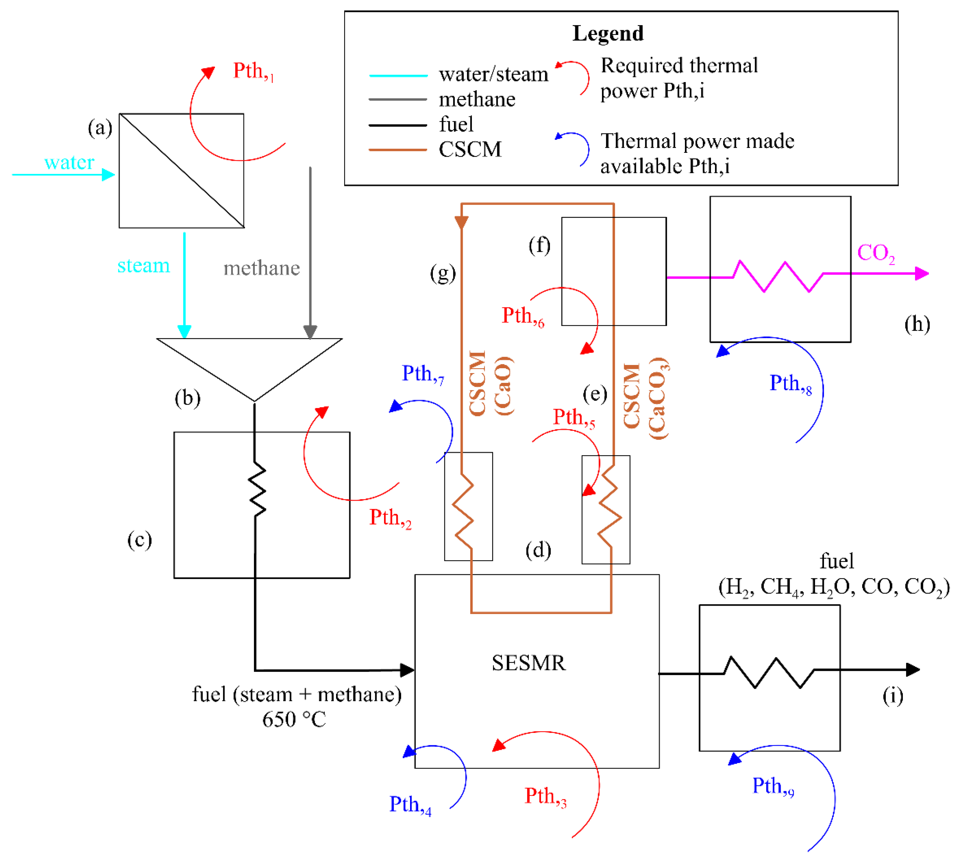
A mathematical model was developed to perform an energy retrofit of the SESMR process. Starting from the experimental configuration, the first step was the schematization of the process from an energy point of view. In the model scheme shown in Figure 1, the power contributions of the main stages of the processes can be recognized:
(a)
Subcooled water enters the evaporator, where it receives a thermal power Pth,1. Due to this thermal exchange, the water leaves the evaporator as superheated vapor (steam) at 300 °C.
(b)
The superheated steam is mixed with methane at ambient temperature.
(c)
The mixture of methane and superheated steam enters a heat exchanger, receiving the thermal power Pth,2 and reaching the state required to be fed into the SESMR reactor.
(d)
The feed (methane and steam) enters the reactor at the required condition (T(d) = 650 °C). From the energy point of view, two situations occur:
(1)
The SMR endothermic Reaction (1) requires a thermal power Pth,3 to be provided to the system. This power also takes into account the slightly exothermic contribution of WGS (2);
(2)
The CBN exothermic Reaction (3) makes the thermal power Pth,4 available.
(e)
The sorbent regeneration at 950 °C requires that a significant amount of thermal power Pth,5 is provided to heat up the CSCM at the temperature in correspondence to that with which the calcination takes place.
(f)
Pth,6 is the power required by the calcination (reverse of Reaction (3)), which is a highly endothermic reaction.
(g)
Subsequently, the regenerated CSCM is cooled down to 650 °C (SESMR condition), making the thermal power Pth,7 available. It is worth stressing that the adopted scheme may represent either a dual fluidized bed reactor with solid recirculation or a packed bed configuration. From an energy perspective, CSCM circulation can explain the thermal power required by the calcination (3), and the cooling of the regenerated CSCM makes Pth,6 available. Therefore, the difference is that in dual inter-circulating fluidized bed conditions, this representation coincides with the physics of the process, whereas, in the case of packed bed reactors, the flow charts reproduce only the thermal power exchange, as the solid is not actually circulated.
(h)
The absorbed CO2 is released once the CSCM regeneration is complete. To store CO2, it should be refrigerated and compressed. For the sake of simplicity, in this phase, only the refrigeration stage is considered to preliminarily assess the thermal power made available, Pth,8.
(i)
Depending on the application, the fuel (H2, CH4, H2O, CO, or CO2) can be subjected to a certain degree of cooling, making the thermal power Pth,9 available.

2.3. Power Contribution Assessment through the Energetic Model of SESMR

To perform an energy assessment of the experimented system, the thermal powers—required or made available—were quantified via the calculation of the thermodynamic conditions of the different involved substances (Appendix A). Thus, the different power contributions were evaluated. The first is the power Pth,1, needed at Step (a), which can be determined by Equation (4), as follows:
P t h , 1 = m . ( a ) ( h ( a ) , o u t h ( a ) i n )
where ṁ(a) is the water mass flow rate, while h(a),out and h(a),in are the enthalpy of the steam at the evaporator outlet and water at the inlet, respectively.
Subsequently, the state of the mixture at Step (b) was determined as follows:
  • The mass conservation was applied, as given by Equation (5), considering the species (steam and methane) involved in the mixture:
    ν j M j = 0
    where νj are stoichiometric coefficients (positive if j is a product, negative if j is a reactant) and Mj is the molecular mass of species j.
  • The thermal power needed by the methane–steam mixture to reach the state required to enters the SESMR reactor is given by Equation (6), as follows:
    P t h , 2 = T c , i n T c , o u t F j c p , j ( T ) d T
    where Fj is the molar flow rate of the j substance of the mixture and cp,j(T) heat at a constant pressure of species j (cp,j) as a function of absolute temperature (T).
  • The thermal power Pth,3 is associated with the overall reaction of SMR (1) and WGS (2). Thus, it is given by Equation (7):
    P t h , 3 ( T ) = F j Δ H ° f , j , 298
    where Δ H ° f , j ,   298 is the heat of formation of chemical species involved in both SMR and WGS reactions. Pth,3 represents the net difference between the power needed by SMR (highly endothermic) and that provided by WGS (slightly exothermic). The energy balance return that the energy requires by the reforming is higher than that made available by the WGS; thus, Pth,3 (8) expresses a power contribution required by the system. The fuel at the inlet is constituted by a mixture of steam and methane, while that at the outlet of the reactor is a reformed gas composed of H2, CO, CO2, CH4, and H2O.
  • Pth,4 (8) represents the thermal power provided by the carbonation which is an exothermic reaction. This energy contribution can be evaluated as follows:
    P t h , 4 ( T ) = F C O 2 Δ H ° f , C B N ,   298
    where F C O 2 is the absorbed CO2 molar flow rate and Δ H ° f , C B N ,   298 is the heat of reaction associated with the carbonation process.
  • As above reported, the sorbent needs the thermal power Pth,5 to reach the condition required by the sorbent regeneration phase, as given by Equation (9).
    P t h , 5 ( T ) = T e , i n T e , o u t F C O 2 x C a C O 3 c p , C S C M ( T ) d T
    where x C a C O 3   is the CaCO3 molar fraction in combined sorption–catalyst material (CSCM) and c p , C S C M ( T ) is the specific heat at a constant pressure of the CSCM.
  • The thermal power required by the calcination Pth,6 is given by Equation (10):
    P t h , 6 ( T ) = F C O 2 ( Δ H ° f , C B N   298 )    
    where ( Δ H ° f , C B N   298 ) is the heat of formation related to the calcination stage.
  • At the end of the calcination stage, the CSCM reaches a temperature equal to 950 °C (Tg,in) in case of severe calcination. Then, CSCM should be cooled down to 650 °C (Tg,out) in such a way that the reforming stage takes place again. Thus, during Step (f), the CSCM cooling makes the thermal power Pth,7 available, as given by Equation (11):
    P t h , 7 ( T ) = T g , i n T g , o u t F C O 2 c p , C S C M ( T ) x C a O d T  
    where x C a O is the CaO molar fraction of CSCM.
It is important to notice that Pth,3, Pth,4, Pth,5, Pth,6 and Pth,7 take place simultaneously during the SESMR processes. The disaggregation was performed to evaluate the thermal power requirements and availability for an energy assessment.
8.
Once the CO2 has been released by the sorbent (g) it must be cooled from Th,in (950 °C) to Th,out and compressed to complete the storage stage. The analysis performed here was pushed until the step that precedes the intercooled compression as the main scope was to define the main source of thermal power needed and made available by the system. In particular, the CO2 cooling provides Pth,8 to the surrounding environment, as in Equation (12):
P t h , 8 ( T ) = T h , i n T h , o u t F C O 2 c p , C O 2 ( T ) d T
9.
In addition, once the fuel has left the reactor, it should be cooled from Ti,in (650 °C) to Ti,out (ambient temperature) to make its condition suitable for storing the hydrogen. The power Pth,9, made available by this cooling, is given by Equation (13):
P t h , 9 ( T ) = T i , i n T i , o u t F j c p , j ( T )   d T
Once the power contributions were evaluated, three performance criteria were developed to assess the goodness of the process from an energy point of view.
The ratio between H2 and CH4 chemical energy is reported by ξH2,A in Equation (14):
ξ H 2 , A = m . H 2 H i H 2 m . C H 4 H i C H 4
being representative of the direct recovery of thermal energy through the reforming process [72].
A further indicator of the energy performance is ηH2,B in Equation (15), which also considers the power required by the process Pth,req, in Equation (16):
η H 2 , B = m . H 2 H i H 2 m . C H 4 H i C H 4 + P t h r e q
P t h r e q = ( P t h , 1 + P t h , 2 + P t h , 3 + P t h , 5 + P t h , 6 ) η b
where ηb is the burning efficiency of the generator adopted to obtain the required thermal power.
The total recovered power was calculated by Equation (17), as follows:
P t h r e c = ( P t h , 4 + P t h , 7 + P t h , 8 + P t h , 9 )   η r e c
where ηrec is the efficiency of the recovery system. The third indicator ηH2,C can be obtained by Equation (18), as follows:
η H 2 , C = m . H 2 H i H 2 m . C H 4 H i C H 4 + P t h r e q P t h r e c  

3. Results

The developed model allows for deeper insight into the energy characterization of the process, thus assessing the thermal power requirements and availability in a SESMR/sorbent-regeneration process. This is the first step to carry out a future optimization of the SESMR process, which is based on the highly energy-intensive SMR.
Due to the large experimental data set, the model was used to provide a detailed energy assessment of the SESMR/sorbent-regeneration process. In particular, the first model input concerned the molar flow rates of the involved substances. A scale factor was used in the energetic model, which multiplies the actual molar flow rates involved in the bench-scale experiments (see Section 2.1). As a matter of fact, the molar flows were rather low for an energy evaluation. The adopted scale factor allowed for referring the whole integrated system to a fed CH4 mass flow rate equaling 1 g/s. In this regard, even though N2 was fed as a carrier gas together with CH4 and steam in the actual SESMR/sorbent regeneration experimental tests [70,72], the presence of N2 was not considered in the model and was a carrier gas added to the gaseous mixture only for bench-scale measurability purposes.
The first evaluation regarding CaO15Ni10 performances over long reforming steps (see Section 2.1) was carried out by a comparison between the first SESMR session and the following processes (SMR+WGS, devoid of any sorption-enhancing effect). Despite the methane conversion of both SESMR and SMR+WGS leading to similar results (Figure 2a), the advantages introduced by CO2 sorption emerged by observing the hydrogen molar fraction in the fuel. Indeed, Figure 2b shows that the SESMR allowed for achieving a higher H2 molar concentration on a dry, dilution-free basis in comparison to the SMR+WGS. When SESMR took place, an average H2 molar fraction of about 90 mol% was observed, which is considerably higher than that obtained through SMR+WGS (about 77 mol%). The reported H2 molar fractions correspond to about 70 mol% and 55 mol%, respectively, on a wet, dilution-free basis (Figure 2b). The energetic model can be considered to have two positive benefits of SESMR towards H2 concentration since the sorption-enhancing process reduces the CO2 concentration in the obtained fuel gas and simultaneously drives reactions to further H2 production.
The advantages introduced by SESMR were also clear from an energy point of view. Indeed, in Figure 3, the trend of ξH2,A can be observed, which expresses the hydrogen chemical energy at the SESMR exit versus the methane one at its inlet (14). Therefore, Figure 3 shows that the SESMR allowed for achieving higher values in comparison to the one obtained with SMR+WGS. In particular, with SESMR, the resulting average value is around 115%, whereas, for SMR+WGS, the trend oscillated more, with ξH2,A ranging between 93% and 103%. It is worth noting that in the SESMR situation, some cases (between cycles 20 and 45) were relatively far from the average trend. This behavior correlated with a slight negative deviation from the set point of the CH4 inlet flow rate, which experimentally occurred during the long reforming steps between cycles 20 and 45. This led to obtain less CH4 and H2 in the gas produced during the affected cycles in comparison to regular operations, and, therefore, to a slight overestimation of CH4 conversion (Figure 2a). In addition, a slight decrease of the H2 fraction on a wet basis was even amplified on a relative basis (Figure 2b).
Once the ξH2,A, was evaluated, the next step for a more thorough energy performance assessment was the characterization of various thermal power contributions required by the process Pth,req (16). Figure 4 reports the percentage distribution of thermal power required by different stages.
The 3.8%, 23.9%, and 4.2% shares of the total required power were related to the water economization, vaporization, and steam superheating, respectively, demonstrating that Pth,1 represented a significant part (31.9%) of the whole Pth,req. Concerning the heating of the feed (steam and methane), Pth,2 accounted for 14.3% of the whole Pth,req, while the reforming process, whose energy impact was reduced by carbonation, represented 12.6% of the total power amount. Figure 4 shows the sorbent regeneration involved the highest impact on power requirements, as the CaCO3 heating represented 18.8% and the calcination 22.4% of Pth,req.
The knowledge about the total power required by the system Pth,req allowed for evaluating the performance index ηH2,B (Figure 5a), which represents the energy efficiency of the integrated process while taking into account the power required by different stages of the system. Figure 5a shows ηH2,B(15) for the SESMR and SMR+WGS cases. It can be observed that SESMR ensured higher values in comparison to those obtained by SMR+WGS. Even though the differences ranged by a few percentage points, the separation of CO2 and H2 (almost pure streams) could not be neglected. The small difference of ηH2,B between the SESMR and SMR+WGS cases was ascribable to the fact that higher Pth,req resulted in SESMR than in SMR+WGS due to the regeneration of the sorbent. Nevertheless, as can be observed in Figure 1 in the SESMR process, several stages made thermal power Pth,rec (18) available, and that can reduce the total energy required by the system. These contributions were related to the following factors:
  • Carbonation;
  • Thermal power made available by CSCM cooling;
  • Thermal power recovered through CO2 cooling;
  • Thermal power recovered through reformed fuel cooling.
On the contrary, for SMR+WGS, there were no stages for recovering thermal power, except for the thermal power recoverable through the fuel cooling. Thus, also considering the thermal power recovered, the performance index ηH2,C (17) was evaluated (Figure 5b). It represents the energy efficiency of the integrated process while taking into account the power contributions required and recoverable in the different stages of the integrated system.
It can be seen that the recovered power allowed for reducing the impact of the power required by the system on the energy efficiency, leading to a ηH2,C of SESMR equal to an average value of 79%, with a remarkable increase in comparison to ηH2,B. Thus, SEMSR allowed for obtaining ηH2,C values significantly higher than those of SMR+WGS (72%), demonstrating the effectiveness of sorption-enhancing, not only in terms of avoided CO2 but also from an energy point of view. In fact, it should be emphasized that the best energy performance ensured with the SESMR process was accompanied by a drastic reduction in CO2 emissions.
The effective integration between the available thermal power and that required for the SESMR process can be seen in Figure 6, where the temperature trend is shown for the different stages as a function of associated thermal power. Figure 6 shows that the thermal power requirements (red line) at different stages can be covered considerably by the thermal power provided by other stages:
  • The carbonation makes Pth,4 available, which reduces the thermal power needed by the reforming process (Pth,3).
  • The thermal power Pth,7, provided by CSCM cooling, can be used to cover part of the remaining Pth,3 and the final stage of the fuel heating up prior to entering the reactor (Pth,2). This means that the thermal power needed to heat up the sorbent for its regeneration can be partially recovered.
  • The cooling of reformed fuel exiting the reactor (Pth,9) provides thermal power needed by the first part of the fuel heating up (Pth,2) and by the steam superheating.
  • The CO2 cooling (Pth,8) partially covers the water vaporization stage. A further contribution can be provided by Pth,9.
Therefore, the water economization, the main part of vaporization (part of Pth,1), and the calcination (Pth,6) emerged as the only stages that would remain uncovered. It is worth to stress that the trends reported in Figure 6 did not consider the heat exchange losses (which could be included in a future improved model) or evaluate the thermal power recovered from reformed fuel and captured CO2 cooling, fixing their minimum temperature at 150 °C. Indeed, the main scope of the study was to perform a preliminary energy characterization of the bench-scale system (1 g/s of fed CH4) to open the way for the optimization of possible industrial SESMR applications.

4. Conclusions

In the present study, a comprehensive thermodynamic model was developed for the stages constituting sorption enhanced steam methane reforming (SESMR) systems in order to assess their energy performance. The model was applied to an actual SESMR bench-scale plant, scaling up involved flow rates to get proper quantities for an energy evaluation. The experimental information provided by previous campaigns allowed for carrying out a detailed energy characterization of the system. Moreover, the benefits introduced by the SESMR were assessed, considering reforming stages in which the sorbent was saturated (and, consequently, assimilable to steam methane reforming and water gas shift (SMR+WGS) without sorption-enhancing). In particular, the following results were observed:
  • Although the methane conversions were quite close, SESMR presented a higher hydrogen molar fraction on a dry (90 mol%) and wet basis (70 mol%), in comparison to SMR+WGS without CO2 adsorption, in agreement with the experimental results.
  • SESMR allowed for achieving a higher value of the first performance index ξH2,A, defined as the ratio between hydrogen and methane chemical energy. The results show that SESMR presented an average ξH2,A equal to 115%, while that of SMR fluctuated between 105% and 95%;
  • Considering the power required by the system (ηH2,B), it was observed that even though the advantages offered by SESMR were still present, they were limited to a few percentage points. This was mainly due to the higher thermal power required by the SESMR loop for sorbent regeneration.
  • The final step of the study demonstrated that in SESMR, a high fraction of the required thermal power could be recovered from energy contributions provided by the carbonation process, sorbent, CO2, and fuel cooling. This allowed for reducing the power demand of the system and improving the plant energy performance. Indeed, considering the contributions of recovered thermal power in the energy performance (ηH2,C), an average value of 79% was observed for SESMR, while for SMR+WGS a maximum value of 72% was observed.
Therefore, the proposed model allows for performing a comprehensive energy analysis of the system, demonstrating that SESMR has benefits not only in terms of hydrogen production and carbon dioxide separation but also referring to the energy performance of the integrated system. Indeed, despite the higher thermal power required in comparison to the SMR+WGS process at the same process conditions (650 °C, 1 atm), the possibility to recover a large fraction of this power improves the energy performance of the entire SESMR/sorbent-regeneration process.

Author Contributions

Conceptualization, F.F., A.D.G., R.C. (Roberto Cipollone), K.G. and R.C. (Roberto Cipollone); methodology, F.F., A.D.G., R.C. (Roberto Cipollone), K.G. and R.C. (Roberto Cipollone); software, R.C. (Roberto Carapellucci), F.F., A.D.G.; validation, F.F., A.D.G., R.C. (Roberto Cipollone), K.G. and R.C. (Roberto Cipollone); formal analysis, F.F., A.D.G., R.C. (Roberto Cipollone), K.G. and R.C. (Roberto Cipollone); investigation, F.F., A.D.G., R.C, K.G. and R.C. (Roberto Cipollone); resources, R.C. (Roberto Cipollone), K.G. and R.C. (Roberto Cipollone); data curation, F.F., A.D.G.; writing—original draft preparation, F.F., A.D.G., R.C. (Roberto Cipollone), K.G. and R.C. (Roberto Cipollone); writing—review and editing, F.F., A.D.G., R.C. (Roberto Cipollone), K.G. and R.C. (Roberto Cipollone); visualization, F.F., A.D.G., R.C. (Roberto Cipollone), K.G. and R.C. (Roberto Cipollone); supervision, R.C. (Roberto Cipollone), K.G. and R.C. (Roberto Cipollone); project administration, R.C. (Roberto Cipollone), K.G. and R.C. (Roberto Cipollone); funding acquisition, R.C. (Roberto Cipollone), K.G. and R.C. (Roberto Cipollone) All authors have read and agreed to the published version of the manuscript.

Funding

The research was developed in the framework of the National Operating Program (PON) for Attraction and International Mobility (AIM)-AIM1829299, a project of the Italian Ministry of University (MIUR) to favor the international research collaboration.

Institutional Review Board Statement

Not applicable.

Informed Consent Statement

Not applicable.

Data Availability Statement

Data is contained within the article.

Conflicts of Interest

The authors declare no conflict of interest.

Nomenclature

Acronyms
CBNCarbonation
CSCMCombined catalyst sorption material
SESMRSorption-enhanced steam–methane reforming
SMR Steam–methane reforming
WGSWater–gas Shift
Symbols
c p , j Specific heat at constant pressure of species j [kJ/(kmolK)]/[kJ/kgK]
FMolar flow rate of species j [kmol/s]
hSpecific enthalpy [kJ/kg]
MMolecular masses [kg/kmol]
Mass flow rate [kg/s]
PthThermal power [W]
TTemperature [K]
Subscripts
(a)Vaporization phase
(b)Steam/methane mixing phase
(c)Fuel heating phase
(d)Sorption-enhanced reforming phase
(e)Sorbent heat up for regeneration
(f)Calcination phase
(g)Sorbent cooling phase
(h)CO2 cooling phase
(i)Fuel cooling phase
jGeneric species
inInlet
outOutlet
Greek symbols
Δ H ° f , i   298 Standard heat of formation of i-substance [kJ/kmol]
ηH2,BH2 production efficiency (without energy recovery)
ηH2,CH2 production efficiency (with energy recovery)
νStochiometric coefficient [kmol]
ξH2,AH2 vs. CH4 chemical energy

Appendix A

This appendix summarizes the calculation methods for thermodynamic properties considered in this work.
Specific heat at a constant pressure of species j (cp,j) as a function of absolute temperature (T) was calculated by (A1), with constants for each species j (aj, bj, cj, dj), as reported in Table A1.
c p , i ( T ) = a j + b j T + c j T 2 + d j T 2         w i t h   c p , j   i n cal mol   K   a n d   T   i n   K
Table A1. Constants for cp,j calculation as a function of absolute temperature, according to A1 (phases: (c) = crystalline; (g) = gas).
jPhaseaj (cal mol−1 K−1)bj (cal mol−1 K−2)cj (cal mol−1 K−3)dj (cal mol−1 K3)Validity (K)Ref.
CaCO3(c)19.680.011890−307,600273–1033[59]
CaO(c)10.000.004840−108,000273–1173[59]
CO2(g)10.340.002740−195,500273–1200[59]
CH4(g)5.340.011500−130,300273–1373[59]
CO(g)6.600.0012000273–2500[59]
H2(g)6.620.0008100273–2500[59]
H2O(g)8.220.000150.000001340300–2500[59]
Ni(cα)4.260.006400273–626[59]
Ni(cβ)6.990.00090500626–1725[59]
NiO(c)11.30.0021500273–1273[59]
O2(g)8.270.0002580−187,700300–5000[59]
Ca12Al14O33(cα)301.960.06550−5,530,000298–1300[60]
Ca12Al14O33(cβ)228.520.09844001300–1700[60]
Concerning the CSCM, its specific heat (cp,CSCM) as a function of T was calculated as the weighted average of cp,j of its chemical components ((A2), Table A1). CSCM compositions (molar fractions xj) depend on their chemical state (reduced or oxidized catalytic phase, calcinated or carbonated sorbent phase).
c p , C S C M ( T ) = x i c p , j ( T )         with   j = Ni ,   NiO ,   CaO ,   CaCO 3 , Ca 12 Al 14 O 33
Let us consider the generic chemical reaction in (A3), where νj is the stoichiometric coefficient (positive if j is a product, negative if j is a reactant) and Mj is the molecular mass of species j. The heat of that reaction as a function of temperature (ΔHR(T)) was calculated by Kirchoff (A4), with the standard heat of (ΔR 298) determined according to Hess’s law (A5), where Δf,j 298 is the standard heat of formation of j shown in Table A2.
ν j M j = 0
Δ H R ( T ) = Δ H ° R   298 + 298.15 T ν j c p , j ( T ) d T
Δ H R   298 = ν j Δ H ° f , j   298
Table A2. Standard heats of formation Δf,j 298 in (A4) (phases: (c) = crystalline; (g) = gas).
jPhaseΔH°f,j 298 (kcal mol−1 K−1)Ref.
CaCO3(c)−289.5[59]
CaO(c)−151.7[59]
CO2(g)−94.052[59]
CH4(g)−17.81[59]
CO(g)−26.416[59]
H2(g)0[59]
H2O(g)−57.7979[59]
Ni(cα)0[59]
Ni(cβ)0[59]
NiO(c)−58.4[59]
O2(g)0[59]

References

  1. UNFCCC. The Paris Agreement. Available online: https://unfccc.int/process-and-meetings/the-paris-agreement/the-paris-agreement (accessed on 17 March 2021).
  2. Normile, D. Can China, the world’s biggest coal consumer, become carbon neutral by 2060? Science 2020. [Google Scholar] [CrossRef]
  3. Claeys, G.; Tagliapietra, S.; Zachmann, G. How to Make the European Green Deal Work. Bruegel Policy Contribution; Bruegel: Brussels, Belgium, 2019; p. 21. [Google Scholar]
  4. European Commission. A European Green Deal. Available online: https://ec.europa.eu/info/strategy/priorities-2019-2024/european-green-deal_en (accessed on 17 March 2021).
  5. European Commission. Recovery Plan for European. Available online: https://ec.europa.eu/info/strategy/recovery-plan-europe_en (accessed on 17 March 2021).
  6. USA Formally Rejoins the Paris Climate Accord. The New York Times. Available online: https://www.nytimes.com/2021/02/19/world/us-rejoins-paris-climate-accord.html (accessed on 17 March 2021).
  7. Obama, B. The irreversible momentum of clean energy. Science 2017, 355, 126–129. [Google Scholar] [CrossRef] [PubMed] [Green Version]
  8. Miller, D.C.; Litynski, J.T.; Brickett, L.A.; Morreale, B.D. Toward transformational carbon capture systems. AIChE J. 2016, 62, 2–10. [Google Scholar] [CrossRef]
  9. Pachauri, R.K.; Meyer, L.; Van Leo, Y.; Brinkman, J.-P.; Van Kesteren, S.; Leprince-Ringuet, L.; Van Noëmie Boxmeer, F. Climate Change 2013-The Physical Science Basis; IPCC: Geneva, Switzerland, 2014; ISBN 9781107415324. [Google Scholar]
  10. Pachauri, R.K.; Allen, M.R.; Barros, V.R.; Broome, J.; Cramer, W.; Christ, R.; Church, J.A.; Clarke, L.; Dahe, Q.; Dasgupta, P.; et al. Climate Change 2014: Synthesis Report. Contribution of Working Groups I, II and III to the Fifth Assessment Report of the Intergovernmental Panel on Climate Change; IPCC: Geneva, Switzerland, 2014; p. 151. ISBN 978-92-9169-143-2. [Google Scholar]
  11. Di Giuliano, A.; Gallucci, K. Sorption enhanced steam methane reforming based on nickel and calcium looping: A review. Chem. Eng. Process.-Process Intensif. 2018, 130, 240–252. [Google Scholar] [CrossRef]
  12. Dawood, F.; Anda, M.; Shafiullah, G.M. Hydrogen production for energy: An overview. Int. J. Hydrogen Energy 2020, 45, 3847–3869. [Google Scholar] [CrossRef]
  13. Wallace, J.S.; Ward, C.A. Hydrogen as a fuel. Int. J. Hydrogen Energy 1983, 8, 255–268. [Google Scholar] [CrossRef]
  14. Vezirolu, T.N.; Barbir, F. Hydrogen: The wonder fuel. Int. J. Hydrogen Energy 1992, 17, 391–404. [Google Scholar] [CrossRef]
  15. Da Silva Veras, T.; Mozer, T.S.; da Costa Rubim Messeder dos Santos, D.; da Silva César, A. Hydrogen: Trends, production and characterization of the main process worldwide. Int. J. Hydrogen Energy 2017, 42, 2018–2033. [Google Scholar] [CrossRef]
  16. Alazemi, J.; Andrews, J. Automotive hydrogen fuelling stations: An international review. Renew. Sustain. Energy Rev. 2015, 48, 483–499. [Google Scholar] [CrossRef]
  17. Toyota Mirai. Toyota Motor Company Hydrogen Fuel Cell Car. Available online: https://ssl.toyota.com/mirai/fcv.html (accessed on 18 September 2017).
  18. Holladay, J.D.; Hu, J.; King, D.L.; Wang, Y. An overview of hydrogen production technologies. Catal. Today 2009, 139, 244–260. [Google Scholar] [CrossRef]
  19. Kothari, R.; Buddhi, D.; Sawhney, R.L. Comparison of environmental and economic aspects of various hydrogen production methods. Renew. Sustain. Energy Rev. 2008, 12, 553–563. [Google Scholar] [CrossRef]
  20. Chaubey, R.; Sahu, S.; James, O.O.; Maity, S. A review on development of industrial processes and emerging techniques for production of hydrogen from renewable and sustainable sources. Renew. Sustain. Energy Rev. 2013, 23, 443–462. [Google Scholar] [CrossRef]
  21. Rostrup-Nielsen, J.R. Catalytic Steam Reforming. Catal. Sci. Technol. 1984, 5, 1–117. [Google Scholar]
  22. Rostrup-Nielsen, T. Manufacture of hydrogen. In Proceedings of the Catalysis Today; Elsevier: Amsterdam, The Netherlands, 2005; Volume 106, pp. 293–296. [Google Scholar]
  23. Harrison, D.P. Sorption-Enhanced Hydrogen Production: A Review. Ind. Eng. Chem. Res. 2008, 47, 6486–6501. [Google Scholar] [CrossRef]
  24. Barelli, L.; Bidini, G.; Gallorini, F.; Servili, S. Hydrogen production through sorption-enhanced steam methane reforming and membrane technology: A review. Energy 2008, 33, 554–570. [Google Scholar] [CrossRef]
  25. Carvill, B.T.; Hufton, J.R.; Anand, M.; Sircar, S. Sorption-enhanced reaction process. AIChE J. 1996, 42, 2765–2772. [Google Scholar] [CrossRef]
  26. Meyer, J.; Mastin, J.; Bjørnebøle, T.-K.; Ryberg, T.; Eldrup, N. Techno-economical study of the Zero Emission Gas power concept. Energy Procedia 2011, 4, 1949–1956. [Google Scholar] [CrossRef] [Green Version]
  27. Martavaltzi, C.S.; Pampaka, E.P.; Korkakaki, E.S.; Lemonidou, A.A. Hydrogen Production via Steam Reforming of Methane with Simultaneous CO2. Chem. Eng. J. 2010, 33, 2589–2595. [Google Scholar] [CrossRef]
  28. Shokrollahi Yancheshmeh, M.; Radfarnia, H.R.; Iliuta, M.C. High temperature CO2 sorbents and their application for hydrogen production by sorption enhanced steam reforming process. Chem. Eng. J. 2016, 283, 420–444. [Google Scholar] [CrossRef]
  29. Martavaltzi, C.S.; Pefkos, T.D.; Lemonidou, A.A. Operational Window of Sorption Enhanced Steam Reforming of Methane over CaO−Ca12Al14O33. Ind. Eng. Chem. Res. 2011, 50, 539–545. [Google Scholar] [CrossRef]
  30. Martavaltzi, C.S.; Lemonidou, A.A. Hydrogen production via sorption enhanced reforming of methane: Development of a novel hybrid material-reforming catalyst and CO2 sorbent. Chem. Eng. Sci. 2010, 65, 4134–4140. [Google Scholar] [CrossRef]
  31. Stanmore, B.R.; Gilot, P. Review-calcination and carbonation of limestone during thermal cycling for CO2 sequestration. Fuel Process. Technol. 2005, 86, 1707–1743. [Google Scholar] [CrossRef]
  32. Diglio, G.; Hanak, D.P.; Bareschino, P.; Pepe, F.; Montagnaro, F.; Manovic, V. Modelling of sorption-enhanced steam methane reforming in a fixed bed reactor network integrated with fuel cell. Appl. Energy 2018, 210, 1–15. [Google Scholar] [CrossRef] [Green Version]
  33. Diglio, G.; Hanak, D.P.; Bareschino, P.; Mancusi, E.; Pepe, F.; Montagnaro, F.; Manovic, V. Techno-economic analysis of sorption-enhanced steam methane reforming in a fixed bed reactor network integrated with fuel cell. J. Power Sources 2017, 364, 41–51. [Google Scholar] [CrossRef] [Green Version]
  34. Meyer, J.; Mastin, J.; Sanz, C. Sustainable Hydrogen Production from Biogas Using Sorption- Enhanced Reforming. Energy Procedia 2014, 63, 6800–6814. [Google Scholar] [CrossRef] [Green Version]
  35. Broda, M.; Manovic, V.; Imtiaz, Q.; Kierzkowska, A.M.; Anthony, E.J.; Müller, C.R. High-Purity Hydrogen via the Sorption-Enhanced Steam Methane Reforming Reaction over a Synthetic CaO-Based Sorbent and a Ni Catalyst. Environ. Sci. Technol. 2013, 47, 6007–6014. [Google Scholar] [CrossRef]
  36. Di Giuliano, A.; Gallucci, K.; Kazi, S.S.; Giancaterino, F.; Di Carlo, A.; Courson, C.; Meyer, J.; Di Felice, L. Development of Ni- and CaO-based mono- and bi-functional catalyst and sorbent materials for Sorption Enhanced Steam Methane Reforming: Performance over 200 cycles and attrition tests. Fuel Process. Technol. 2019, 195, 106160. [Google Scholar] [CrossRef]
  37. García-Lario, A.L.; Aznar, M.; Martinez, I.; Grasa, G.S.; Murillo, R. Experimental study of the application of a NiO/NiAl2O catalyst and a CaO-based synthetic sorbent on the Sorption Enhanced Reforming process. Int. J. Hydrogen Energy 2015, 40, 219–232. [Google Scholar] [CrossRef]
  38. Satrio, J.A.; Shanks, B.H.; Wheelock, T.D. Development of a novel combined catalyst and sorbent for hydrocarbon reforming. Ind. Eng. Chem. Res. 2005, 44, 3901–3911. [Google Scholar] [CrossRef] [Green Version]
  39. Satrio, J.A.; Shanks, B.H.; Wheelock, T.D. A combined catalyst and sorbent for enhancing hydrogen production from coal or biomass. Energy Fuels 2007, 21, 322–326. [Google Scholar] [CrossRef] [Green Version]
  40. Cesário, M.R.; Barros, B.S.; Zimmermann, Y.; Courson, C.; Melo, D.M.A.; Kiennemann, A. CO2 Sorption Enhanced Steam Reforming of Methane Using Ni/CaO · Ca12Al14O33 Catalysts. Adv. Chem. Lett. 2013, 1, 292–299. [Google Scholar] [CrossRef] [Green Version]
  41. Xu, P.; Zhou, Z.; Zhao, C.; Cheng, Z. Ni/CaO-Al2O3 bifunctional catalysts for sorption-enhanced steam methane reforming. AIChE J. 2014, 60, 3547–3556. [Google Scholar] [CrossRef]
  42. Radfarnia, H.R.; Iliuta, M.C. Development of Al-stabilized CaO–nickel hybrid sorbent–catalyst for sorption-enhanced steam methane reforming. Chem. Eng. Sci. 2014, 109, 212–219. [Google Scholar] [CrossRef]
  43. Xu, P.; Zhou, Z.; Zhao, C.; Cheng, Z. Catalytic performance of Ni/CaO-Ca5Al6O14 bifunctional catalyst extrudate in sorption-enhanced steam methane reforming. Catal. Today 2016, 259, 347–353. [Google Scholar] [CrossRef]
  44. Rout, K.R.; Jakobsen, H.A. A numerical study of pellets having both catalytic- and capture properties for SE-SMR process: Kinetic- and product layer diffusion controlled regimes. Fuel Process. Technol. 2013, 106, 231–246. [Google Scholar] [CrossRef]
  45. Kim, J.-N.; Ko, C.H.; Yi, K.B. Sorption enhanced hydrogen production using one-body CaO–Ca12Al14O33–Ni composite as catalytic absorbent. Int. J. Hydrogen Energy 2013, 38, 6072–6078. [Google Scholar] [CrossRef]
  46. Chanburanasiri, N.; Ribeiro, A.M.; Rodrigues, A.E.; Arpornwichanop, A.; Laosiripojana, N.; Praserthdam, P.; Assabumrungrat, S. Hydrogen Production via Sorption Enhanced Steam Methane Reforming Process Using Ni/CaO Multifunctional Catalyst. Ind. Eng. Chem. Res. 2011, 50, 13662–13671. [Google Scholar] [CrossRef]
  47. Aloisi, I.; Jand, N.; Stendardo, S.; Foscolo, P.U. Hydrogen by sorption enhanced methane reforming: A grain model to study the behavior of bi-functional sorbent-catalyst particles. Chem. Eng. Sci. 2016, 149, 22–34. [Google Scholar] [CrossRef]
  48. Aloisi, I.; Di Giuliano, A.; Di Carlo, A.; Foscolo, P.U.; Courson, C.; Gallucci, K. Sorption enhanced catalytic Steam Methane Reforming: Experimental data and simulations describing the behaviour of bi-functional particles. Chem. Eng. J. 2016, 314, 570–582. [Google Scholar] [CrossRef]
  49. Di Giuliano, A.; Aloisi, I.; Jand, N.; Foscolo, P.U.; Courson, C.; Gallucci, K. Sorption enhanced steam methane reforming: Experimental data and simulations describing the behaviour of bi-functional particles. In Proceedings of the WHEC 2016-21st World Hydrogen Energy Conference 2016, Zaragoza, Spain, 13–16 June 2016; Spanish Hydrogen Association (AeH2): Zaragoza, Spain, 2016; Volume 1, pp. 111–113. [Google Scholar]
  50. Martínez, I.; Romano, M.C.; Chiesa, P.; Grasa, G.; Murillo, R. Hydrogen production through sorption enhanced steam reforming of natural gas: Thermodynamic plant assessment. Int. J. Hydrogen Energy 2013, 38, 15180–15199. [Google Scholar] [CrossRef]
  51. Ochoa-Fernandez, E.; Haugen, G.; Zhao, T.; Ronning, M.; Aartun, I.; Borresen, B.; Rytter, E.; Rønnekleiv, M.; Chen, D. Process design simulation of H2 production by sorption enhanced steam methane reforming: Evaluation of potential CO2 acceptors. Green Chem. 2007, 9, 654–662. [Google Scholar] [CrossRef]
  52. Romano, M.C.; Cassotti, E.N.; Chiesa, P.; Meyer, J.; Mastin, J. Application of the sorption enhanced-steam reforming process in combined cycle-based power plants. Energy Procedia 2011, 4, 1125–1132. [Google Scholar] [CrossRef] [Green Version]
  53. Carapellucci, R.; Giordano, L. dry and autothermal methane reforming for hydrogen production: A thermodynamic equilibrium analysis. J. Power Sources 2020, 469, 228391. [Google Scholar] [CrossRef]
  54. Lopez Ortiz, A.; Harrison, D.P. Hydrogen production using sorption-enhanced reaction. Ind. Eng. Chem. Res. 2001, 40, 5102–5109. [Google Scholar] [CrossRef]
  55. Brun-Tsekhovoi, A.R.; Zadorin, A.N.; Katsobashvili, Y.R.; Kourdyumov, S.S. The process of catalytic steam reforming of hydrocarbons in the presence of carbon dioxide acceptor. In Hydrocarbon Energy Progress VII, Proceedings of the 7th World Hydrogen Energy Conference, Moscow, Russia, 25–29 September 1988; Pergamon Press: Oxford, UK; p. 885.
  56. Han, C.; Harrison, D.P. Simultaneous shift reaction and carbon dioxide separation for the direct production of hydrogen. Chem. Eng. Sci. 1994, 49, 5875–5883. [Google Scholar] [CrossRef]
  57. Balasubramanian, B.; Lopez Ortiz, A.; Kaytakoglu, S.; Harrison, D.P. Hydrogen from methane in a single-step process. Chem. Eng. Sci. 1999, 54, 3543–3552. [Google Scholar] [CrossRef]
  58. Antzara, A.; Heracleous, E.; Lemonidou, A.A. Energy efficient sorption enhanced-chemical looping methane reforming process for high-purity H2 production: Experimental proof-of-concept. Appl. Energy 2016, 180, 457–471. [Google Scholar] [CrossRef]
  59. Wang, S.; Xu, S.; Liu, S.; Hu, B. Prediction of sorption-enhanced reforming process on hydrotalcite sorbent in a fluidized bed reactor. Energy Convers. Manag. 2019, 180, 924–930. [Google Scholar] [CrossRef]
  60. Vicente, J.; Montero, C.; Ereña, J.; Azkoiti, M.J.; Bilbao, J.; Gayubo, A.G. Coke deactivation of Ni and Co catalysts in ethanol steam reforming at mild temperatures in a fluidized bed reactor. Int. J. Hydrogen Energy 2014, 39, 12586–12596. [Google Scholar] [CrossRef]
  61. Fernández, J.R.; Martínez, I.; Abanades, J.C.; Romano, M.C. Conceptual design of a Ca–Cu chemical looping process for hydrogen production in integrated steelworks. Int. J. Hydrogen Energy 2017, 42, 11023–11037. [Google Scholar] [CrossRef]
  62. Noorman, S.; van Sint Annaland, M.; Kuipers, H. Packed Bed Reactor Technology for Chemical-Looping Combustion. Ind. Eng. Chem. Res. 2007, 46, 4212–4220. [Google Scholar] [CrossRef] [Green Version]
  63. Di Giuliano, A.; Giancaterino, F.; Courson, C.; Foscolo, P.U.; Gallucci, K. Development of a Ni-CaO-mayenite combined sorbent-catalyst material for multicycle sorption enhanced steam methane reforming. Fuel 2018, 234, 687–699. [Google Scholar] [CrossRef]
  64. Di Giuliano, A.; Pellegrino, E. Numerical integration strategies of PFR dynamic models with axial dispersion and variable superficial velocity: The case of CO2 capture by a solid sorbent. Heliyon 2019, 5, e02040. [Google Scholar] [CrossRef]
  65. Di Giuliano, A.; Girr, J.; Massacesi, R.; Gallucci, K.; Courson, C. Sorption enhanced steam methane reforming by Ni–CaO materials supported on mayenite. Int. J. Hydrogen Energy 2017, 42, 13661–13680. [Google Scholar] [CrossRef]
  66. Di Giuliano, A.; Giancaterino, F.; Gallucci, K.; Foscolo, P.U.; Courson, C. Catalytic and sorbent materials based on mayenite for sorption enhanced steam methane reforming with different packed-bed configurations. Int. J. Hydrogen Energy 2018, 43, 21279–21289. [Google Scholar] [CrossRef]
  67. Di Giuliano, A.; Gallucci, K.; Giancaterino, F.; Courson, C.; Foscolo, P.U. Multicycle sorption enhanced steam methane reforming with different sorbent regeneration conditions: Experimental and modelling study. Chem. Eng. J. 2019, 377, 119874. [Google Scholar] [CrossRef]
  68. Di Giuliano, A.; Gallucci, K.; Foscolo, P.U.; Courson, C. Effect of Ni precursor salts on Ni-mayenite catalysts for steam methane reforming and on Ni-CaO-mayenite materials for sorption enhanced steam methane reforming. Int. J. Hydrogen Energy 2019, 44, 6461–6480. [Google Scholar] [CrossRef]
  69. Di Giuliano, A.; Gallucci, K.; Di Carlo, A.; Stendardo, S.; Courson, C.; Foscolo, P.U. Sorption enhanced steam methane reforming by mayenite combined systems: Overview of experimental results from uropean research project. Can. J. Chem. Eng. 2020, 98, 1907–1923. [Google Scholar] [CrossRef]
  70. Di Giuliano, A.; Courson, C.; Gallucci, K.; Kiennemann, A. Ni-CaO combined sorbent-catalyst materials usage for sorption enhanced steam methane reforming. In Proceedings of the WHEC 2016-21st World Hydrogen Energy Conference 2016, Zaragoza, Spain, 13–16 June 2016; Spanish Hydrogen Association (AeH2): Zaragoza, Spain, 2016; pp. 68–70. [Google Scholar]
  71. Di Giuliano, A.; Gallucci, K.; Foscolo, P.U. Determination of Kinetic and Diffusion Parameters Needed to Predict the Behavior of CaO-Based CO2 Sorbent and Sorbent-Catalyst Materials. Ind. Eng. Chem. Res. 2020, 59, 6840–6854. [Google Scholar] [CrossRef]
  72. Carapellucci, R. A unified approach to assess performance of different techniques for recovering exhaust heat from gas turbines. Energy Convers. Manag. 2009, 50, 1218–1226. [Google Scholar] [CrossRef]
Figure 1. Scheme of the energetic model of SESMR.
Processes 09 01440 g001
Figure 2. Methane conversion (a) and hydrogen molar fraction dry and wet basis for SESMR and SMR+WGS (b). Data adapted from Di Giuliano et al. [63].
Processes 09 01440 g002
Figure 3. Hydrogen versus methane chemical energy χ H2,A for SESMR and SMR.
Processes 09 01440 g003
Figure 4. Contributions (%) of the whole thermal power required by SESMR.
Processes 09 01440 g004
Figure 5. Hydrogen production efficiency (a) ηH2,B without thermal energy recovery and (b) ηH2,C with thermal energy recovery for SESMR and SMR.
Processes 09 01440 g005
Figure 6. Temperature as a function of thermal power for different SESMR stages (red lines are the required powers, blue lines are the available powers).
Processes 09 01440 g006
Publisher’s Note: MDPI stays neutral with regard to jurisdictional claims in published maps and institutional affiliations.

