Article

Designed a Passive Grinding Test Machine to Simulate Passive Grinding Process

1
Key Lab of Metastable Materials Science & Technology, Hebei Key Lab for Optimizing Metal Product Technology and Performance, College of Materials Science & Engineering, Yanshan University, Qinhuangdao 066004, China
2
Henan Engineering Lab for Super-Hard Grinding Composites, Henan University of Technology, Zhengzhou 450007, China
*
Authors to whom correspondence should be addressed.
Processes 2021, 9(8), 1317; https://doi.org/10.3390/pr9081317
Submission received: 10 July 2021 / Revised: 27 July 2021 / Accepted: 27 July 2021 / Published: 29 July 2021
(This article belongs to the Special Issue Advance in Machine Learning)

Abstract

:
Passive grinding is a high-speed rail grinding maintenance strategy, which is completely different from the conventional rail active grinding system. In contrast to active grinding, there is no power to drive the grinding wheel to rotate actively in passive grinding. The passive grinding process is realized only by the cooperation of grinding pressure, relative motion, and deflection angle. Grinding tests for passive grinding can help to improve the passive grinding process specifications and be used for the development of passive grinding wheels. However, most of the known grinding methods are active grinding, while the passive grinding machines and processes are rarely studied. Therefore, a passive grinding test machine was designed to simulate passive grinding in this study. This paper gives a detailed description and explanation of the structure and function of the passive grinding tester. Moreover, the characteristics of the grinding process and parameter settings of the testing machine were discussed based on the passive grinding principle. The design of a passive grinding test machine provides experimental equipment support for investigating passive grinding behavior and grinding process.

1. Introduction

In the past 40 years, the railway industry has experienced unprecedented development worldwide [1,2]. With the advancement of railway technology, the destructive effect of trains on rails has also enhanced significantly [3]. The rail defects and rolling-contact fatigue (RCF) on the rail surface emerge an enlarged and continuous distribution [4,5]. The increase and severity of rail damage have brought great challenges to rail maintenance.
Many studies have analyzed and discussed the factors that affect rail safety and infrastructure. Markine et al. [6,7] believed that the RCF on the railway switch (turnout) can be combated by tuning the elastic track properties and presented an integrated approach for analysis and improvement of the performance of railway crossings. These studies provide theoretical and methodological supports for the analysis and improvement of the performance of railway turnouts. A. Kampczyk [8,9] studied the geometry and measurement methods of rails and railway infrastructure. The studies guide the optimization of the morphology and safety of the railway. Dindar et al. [10,11] investigated the causes of train derailments on switches and crossings, and identified appropriate risk analysis techniques for railway turnout systems. The risk assessment of train operations helped to develop maintenance standards for rails.
For the safe operation of trains and the stability of infrastructure railways, rail grinding is currently the most commonly used rail maintenance strategy [12]. To meet the maintenance requirements of various railroads, various grinding techniques are applied to rail grinding operations [13]. The traditional method of rail grinding is the active grinding process, which is a maintenance strategy invented to repair rail damage [14]. It is restorative grinding maintenance that focuses on eliminating the existing rail defects affecting train operation through rail removal [15]. Restorative rail maintenance can be carried out in many ways, including planing, milling, and grinding of rails. Planing and milling are suitable for repairing severely damaged rails. They are not commonly used due to a very large amount of rail removal. In this study, only the commonly used rail grinding process is discussed. Rail active grinding, as a mature rail maintenance technology, has many advantages such as stable repair effect and high grinding removal efficiency [16], but it also has the limitations of the application. The forward speed of the active grinding train is relatively slow, which is only 3–15 km/h [17]. With the increase in train length and departure frequency of rail, the on-line operation time for rail maintenance in the railway operating plan is greatly compressed. In recent years, the concept of rail maintenance has gradually changed from the single repair grinding with heavy metal removal amount to preventive grinding operation with short intervals and less metal removal amount. Regular preventive grinding reduces railroad occupancy time and rail grinding consumed. For railways that do not need to be repaired and only require regular preventive grinding maintenance, active grinding takes up a lot of “skylight time” of the rail due to the slow forward speed [18,19]. Moreover, rail preventive grinding does not require a large amount of rail removal, and a small amount of rail removal can be completed rail maintenance to prevent rail disease [20]. Meanwhile, the small amount of rail removal can extend the service life of the rail compared to restorative grinding. As a consequence, a high-speed grinding process (i.e., passive grinding process), mainly applied to the rail preventive grinding, was developed to make up for the shortcomings of rail active grinding.
Passive grinding is called high-speed grinding because the forward speed of the grinding train can reach 60–80 km/h [21]. This high-speed operation is related to the process of passive grinding. In passive grinding, the grinding wheel is not driven by a motor to actively rotate. The grinding wheel relies on the friction generated by the relative movement of the grinding train and the rail under the condition of pressure contact with the rail to rotate [22]. Hence, the high-speed running of the grinding train is one of the necessary conditions to achieve passive grinding. This high-speed operation is completely different from active rail grinding. This also makes the passive grinding process only suitable for grinding continuous railways, and it is not suitable for grinding the turnouts.
The common active grinding process of rails has been studied in many studies on the grinding principle and the matching grinding wheels due to its early appearance and mature technology. Grinding tests on railroads would be wasteful in resources and costly [23], so most of the studies were done by simulated grinding process [24]. These are inseparable from the equipment support provided by a well-established active grinding test machine. Wu et al. [25] investigated the effect of grinding pressure on a brazed diamond sheet for rail’s composite grinding wheel by a vertical active grinding test machine. The vertical grinding test machine simulated the process of active grinding of rails. Uhlmann et al. [26] studied the influence of rail grinding process parameters on rail surface roughness and surface layer hardness with a test rig for rail grinding at IWF. The test rig for rail grinding was developed on a face and profile grinding machine Profimat 408 of Blohm Jung GmbH. Zhe et al. [27] explored the effect of contact pressure on the performance of rail grinding belts using an abrasive belt test apparatus. The testing apparatus provided sufficient data in terms of abrasive belt speed, contact normal force, and grinding power through various sensors for subsequent analysis. Gu et al. [28] developed a horizontal rail grinding friction testing apparatus to simulate the rail active grinding interactions between rail and the grinding wheels. The authors analyzed the effects of the rotational speed of grinding stone on removal behavior of rail material through studying the grinding process. Pereverzev et al. [29] studied the process of plunge circular grinding workpieces on numerically controlled (NC) cylindrical grinders. This study established a grinding force model for active cylindrical grinding. However, passive grinding theory and grinding processes are rarely researched. Additionally, there is no research on passive grinding test equipment. The lack of a passive grinding test machine makes it impossible to simulate the passive grinding process under laboratory conditions, which hinders the study of passive grinding behavior. Therefore, this study developed a passive grinding test machine to simulate passive grinding based on the passive grinding principle. The passive grinding tester can provide equipment support for studying the technical parameters of passive grinding and the performance of passive grinding wheels.
In this study, the passive grinding process was focused on, and a passive grinding machine was designed for passive grinding tests regarding the structure and grinding principle of the rail passive grinding mechanism. The operation of the grinding machine simulating the passive grinding process and the mechanical structure of the grinding machine were described in detail. Additionally, the method of monitoring the grinding force and grinding temperature was explained. Furthermore, to ensure the operation of the passive grinding process on the test machine, the influence of the deflection angle of the grinding wheel on the passive grinding process was discussed. The feasibility of the passive grinding machine was also confirmed by comparing the characteristics of the grinding marks. Meanwhile, the conversion method of the grinding pressure of the passive grinding test machine simulating actual working conditions was explained. These provided the material and theoretical basis for experiments and research on passive grinding.

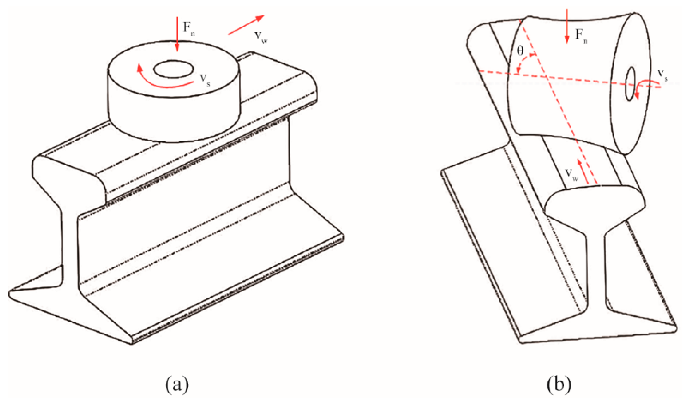
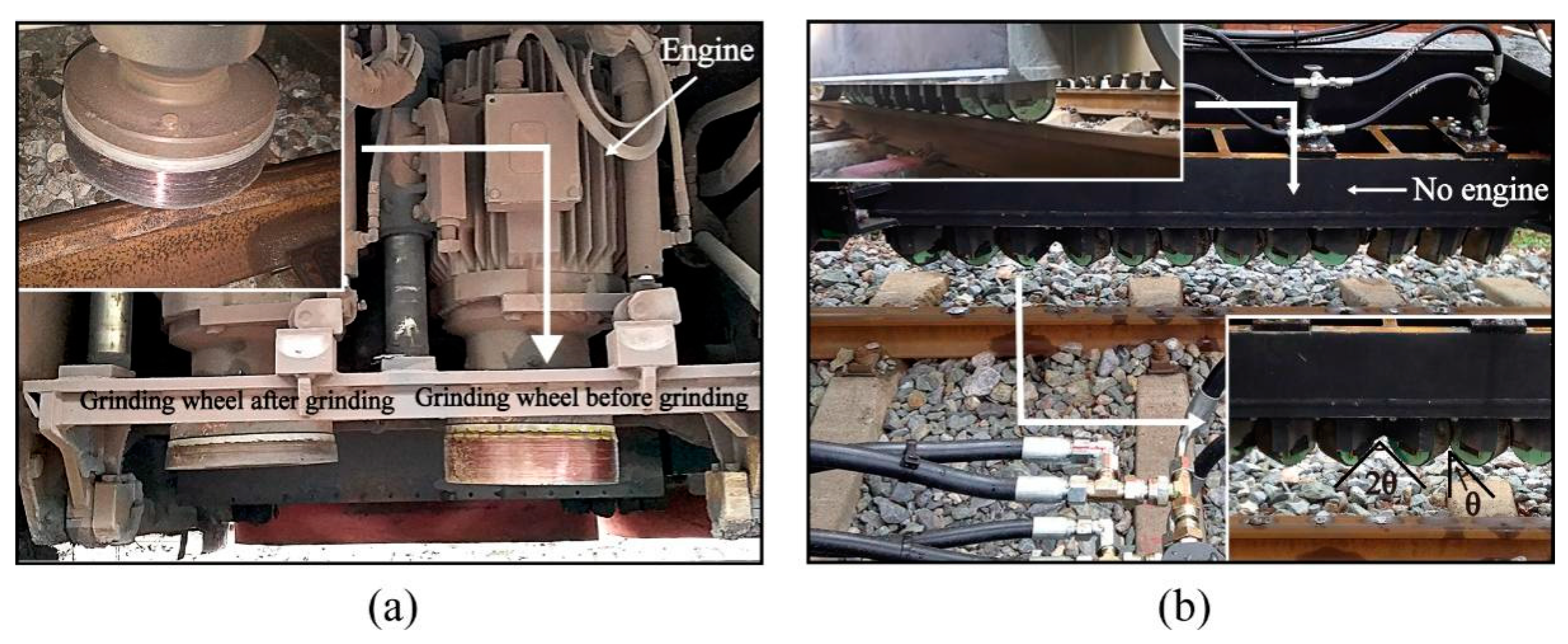
2. Rail Grinding Machine and Grinding Process

Passive rail grinding technology does not have the process of tool planing the rail, only grinding the rail with grinding wheels to remove the defects on the rail surface. Comparing and analyzing active grinding and passive grinding helps to better understand the characteristics of passive grinding, which provides theoretical support for the design of a passive grinding test machine. The structure and grinding process of the grinding machines for active and passive grinding of rails are completely different. The installation conditions of grinding machines are shown in Figure 1.
Figure 1a,b show the grinding mechanism of the GMC-96x type rail active grinding train and the HSG (test type) rail passive grinding train, respectively. Both active and passive rail grinding technology can realize full-angle reprofiling or partial-angle reprofiling of the rail by adjusting the grinding angle of the grinding wheels. The main difference between active grinding and passive grinding is whether the grinding wheels are driven by an engine to achieve autonomous rotation. In the active grinding process, each grinding wheel is separately connected with a set of grinding mechanisms (Figure 1a). The engine in the grinding mechanism provides the grinding wheel with the power for active rotation, and the grinding wheel obtains a definite linear velocity (vs). Under pressure (Fn), active grinding wheels move along the railway with the grinding train (vw) and grind the rail with the end-face to obtain the target contour and surface quality. The grinding process of active rail grinding is shown in Figure 2a. The factors that affect the effect of active grinding include the linear velocity of grinding wheels and grinding pressure.
In the passive grinding process, the grinding method of the grinding wheel is cylindrical grinding instead of end-face grinding, as shown in Figure 2b. The grinding wheel is at an angle (θ) to the rail. The grinding mechanism only provides a pressure load for grinding wheels, but not rotating power (Figure 1b). The passive grinding wheel follows the movement of the grinding train along the railway under the pressure and the deflection angle, resulting in rotation and grinding behavior. Therefore, the grinding process of the grinding wheels on the rail, namely the generation of linear velocity (vs), is influenced by the combination of the deflection angle of the grinding wheel (θ), the grinding pressure (Fn), and the relative speed of grinding wheel and rail (vw). The grinding pressure and the speed of the grinding train directly determine the rail removal amount and grinding efficiency in passive grinding [30]. Additionally, the deflection angle (θ) is the necessary condition to ensure the passive rotation of the wheel in passive grinding.

3. Design of the Passive Grinding Test Machine

The passive grinding train can operate at speeds of up to nearly 100 km/h. Frequent passive grinding tests on railway lines are costly, and it is difficult to measure the grinding process due to the high speed of trains. To conduct grinding tests conveniently and with less expenditure to save resources, the simulation of a passive grinding process is an effective method. However, relative motion is a necessary condition for passive grinding. The difficulty in developing a passive grinding test machine is how to realize the relative motion of the grinding wheel and the workpiece in a small space to make the grinding wheel produce passive grinding behavior. This is one of the reasons why there are few studies on passive grinding. Accordingly, a passive grinding test machine was designed to simulate the passive grinding behavior and passive grinding process with reference to the grinding principle of rail passive grinding. The tester was proposed to study the passive grinding process and passive grinding wheels, but not to completely restore the field operation of high-speed rail grinding.

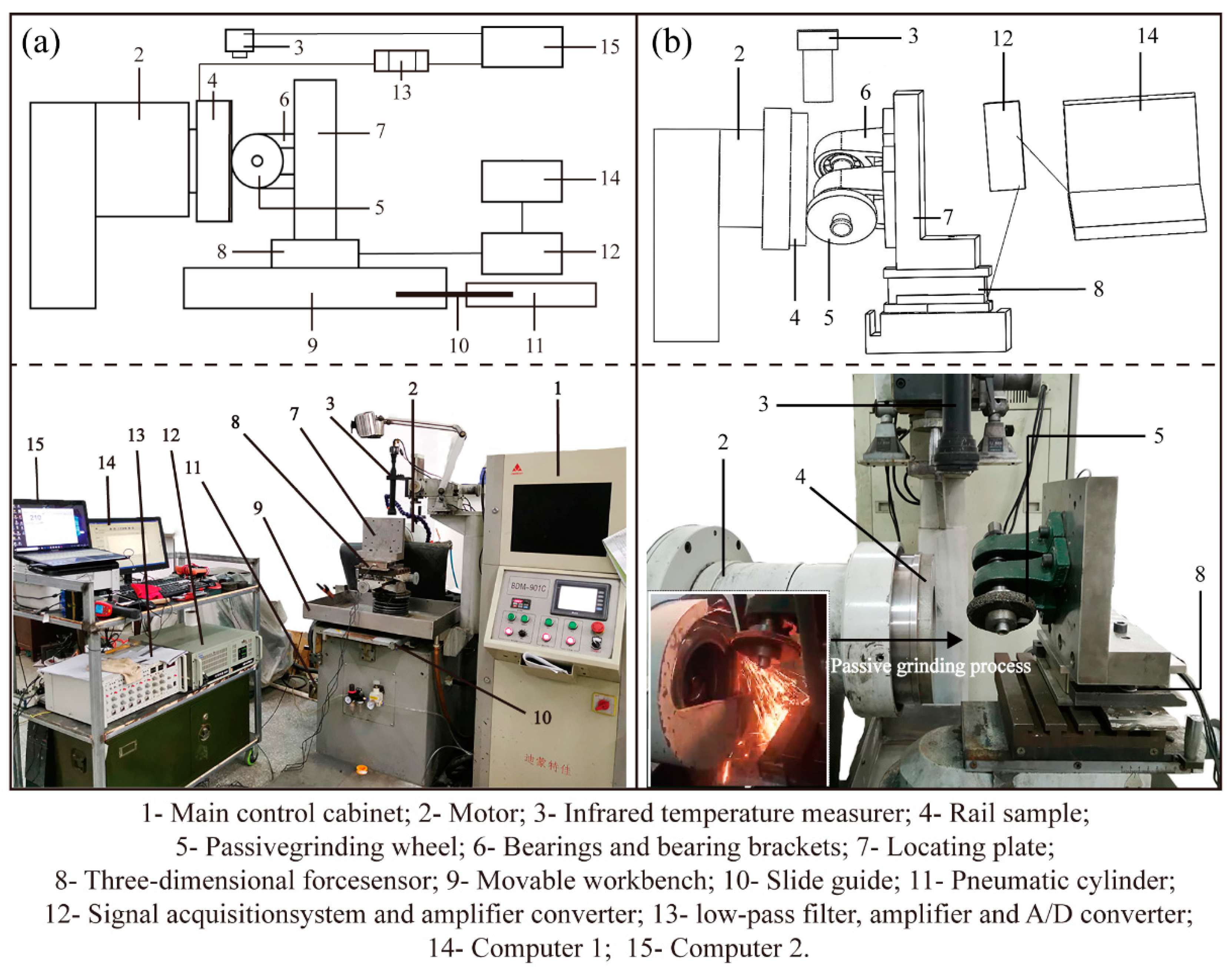
3.1. Structure of the Passive Grinding Machine

The structure of the passive grinding test machine is shown in Figure 3. The overall structure of the grinding tester primarily consisted of a rail drive system, wheel grinding mechanism, and monitoring equipment (Figure 3a). The passive grinding process was achieved by the cooperation of the actively rotating rail specimen driven by the motor (2) and the passive grinding wheel (5) that had no active rotating power (Figure 3b). The grinding tester generated relative motion with the grinding wheel mechanism through the rotation of the rail sample to simulate passive grinding behavior. In the structure of grinding, the passive grinding wheel (5) was positioned horizontally on a locating plate (7) at an angle of θ through the bearing and bearing brackets (6), allowing face-to-face contact with the rail sample and rotate freely without resistance under the action of external force. The wheel grinding mechanism was fixed in its entirety on a movable workbench (9), which is connected with a pneumatic cylinder (11) through a sliding guide (10). During the grinding test process, the pneumatic cylinder (11) was used to provide pressure load by driving the movable workbench (9) to move through the slide guide (10) to make the grinding wheel contact with the rail sample and apply constant pressure. The infrared temperature measurer (3) and a built-in temperature measurement system were used to measure the grinding temperature and the heat generated during the grinding process. The sensors were mounted on the locating plate (7), and the host of the three-dimensional force sensor (8) was placed below the locating plate (7) to measure the grinding forces. The grinding test parameters such as the rotation speed of the rail sample, the contact pressure load, and the grinding time were controlled by the main control cabinet (1).
It should be noted that the rail sample was designed in a circular shape to achieve continuous operation of the passive grinding in a limited space. As shown in Figure 4a, the rail sample used in this study is cut from the on-site rail (Chinese brand: U71Mn), which is the most common material used in China’s high-speed railway [31]. The rail for making the circular sample was standard size with a width of 68 mm. The diameter of the designed rail sample is 150 mm. According to the size of the rail sample, the rotation speed of the sample required for different passive grinding tests can be calculated. In the simulation test of rail passive grinding, the linear velocity of the rail sample rotation can be approximated as simulating the running speed of the grinding train. The conversion relationship between the rotation speed (r/min) of the rail sample and the grinding train is shown in Equation (1).
Rotation   speed   r / min = v w km / h × 10 6 π × d s × 60  
In the formula, vw (km/h) is the speed of the grinding train, and ds (mm) is the diameter of the rail sample. In addition, the size of the passive grinding wheel for the test machine was designed to match the rail sample with 80 mm × 10 mm × 10 mm. The position where the grinding wheel contacted the rail sample was the outermost and midline on the end surface of the rail sample. Under the pressure load and the angle θ, the relative motion between the rail sample and passive grinding wheel was produced and the passive grinding was carried out (Figure 4b).

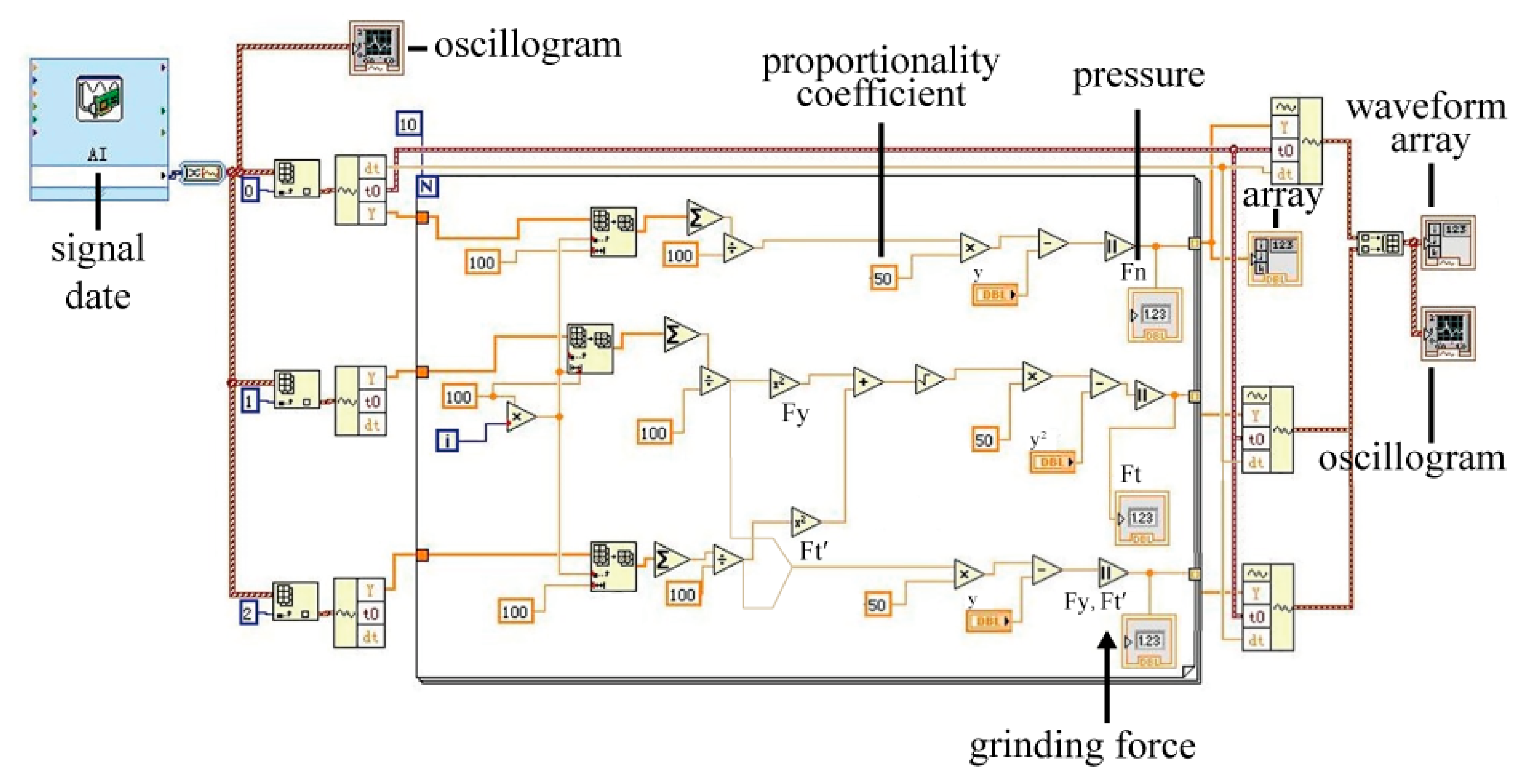
3.2. Force Measurement of the Passive Grinding Machine

The grinding force can reflect the grinding process [32]. Monitoring the variation of forces during the grinding process can help analyze the passive grinding behavior of the grinding wheel on the rail sample under the set grinding conditions. The three-dimensional mechanical sensor (8) was used to measure the grinding pressure (Fn), the grinding tangential force (Ft) along the direction of grinding wheel rotation, and the longitudinal grinding force (Fy) in the axial direction of the grinding wheel. The collected mechanical signals were processed by the Labview force measurement system through the signal acquisition system and amplifier converter (12) and then summarized in the computer (14) to obtain the waveform array and oscillogram. The grinding forces (Ft) and (Fy) were displayed separately, and the resultant force Ft of the grinding force was calculated in Labview by Equation (2).
F t = F t′ 2 + F y 2
The unit of measurement for grinding force is “N”. The processing of signal data in the Labview system is shown in Figure 5. The effects of grinding deflection angle and grinding force on the passive grinding process are analyzed in detail in the following discussion section. Due to the grinding wheel and the supporting part having dead weight, the tangential component of gravity direction was measured and zeroed before each test. The axial load should be calibrated before the test since the load characteristics of the pressure cylinder.

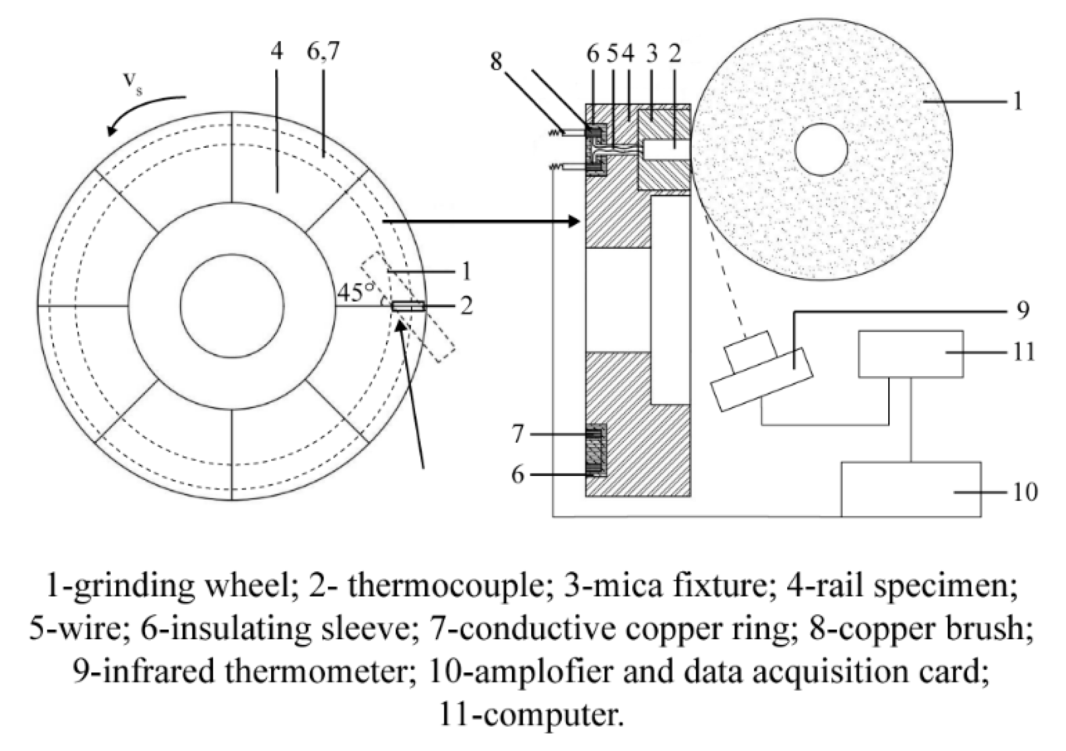
3.3. Temperature Measurement of the Passive Grinding Machine

The heat generated in the passive grinding process will affect the grinding performance of the grinding wheel and the surface quality of the rail [33]. Recording the grinding heat generated in the passive grinding process can conduce to the study of passive grinding. The passive grinding test machine was designed with an infrared thermometer to measure the grinding temperature. However, the most accurate measurement position, namely the grinding contact point between the grinding wheel and the rail, was obscured by the grinding wheel. This may cause measurement errors. Therefore, an insertion temperature measurement system was modified to measure and verify the grinding temperature, and its structure is shown in Figure 6.
The thermocouple (2) in the temperature measurement system is a nickel–chromium/nickel–silicon thermocouple (wafer with thickness of 0.05 mm), which has been calibrated before installation and its temperature measurement range is 0–1000 °C. It is surrounded by insulating film but the top is exposed for direct contact with the grinding wheel. The NiCr-NiSi thermocouple (2) is clamped between the rail specimens and fixed with mica fixture (3). The thermocouple temperature measuring principle is based on the thermoelectric effect. During the grinding process, the nickel–chromium pieces and nickel–silicon pieces are lapped together by the grinding force to form an electric coupling contact and thus a circuit. As shown in Equation (3), the temperature difference causes the thermoelectric potential between the rail material and thermocouple in the circuit loop [34,35].
E = T 1 T 2 × S B
In Equation (3), E (V) is the thermoelectric potential (i.e., the voltage difference), T1 (°C) is the temperature of the rail sample, T2 (°C) is the temperature of the thermocouple, SB is the Seebeck constant. The thermoelectric potential (E) generated by the thermocouple is delivered to the temperature acquisition module through wires (5) and brushes (8). Since the rail specimen (4) is rotating during the test, a conductive copper ring (7) wrapped in an insulating sleeve (6) is designed to embed at the bottom of the rail specimen. The copper brush (8) is always in contact with the conductive copper ring (7) so that the electrical signal can be continuously received while grinding.
It is notable that the original signal is very small (about 0–40 mV) and contains lots of high-frequency noises. Therefore, a low-pass filter (passing frequency ≤20 Hz) and amplifier (enlarge 100 times) are necessary. The signals are transformed into digital signals through the A/D converter and stored in the computer (15). To weaken the vibration interference to improve the signal stability, firstly, an insulating fixture was used to prevent the interference signals coming from the grinding machine; secondly, a real-time voltage monitor was used in this system to monitor the normal operation of the signal measuring system in the grinding process.

4. Discussion

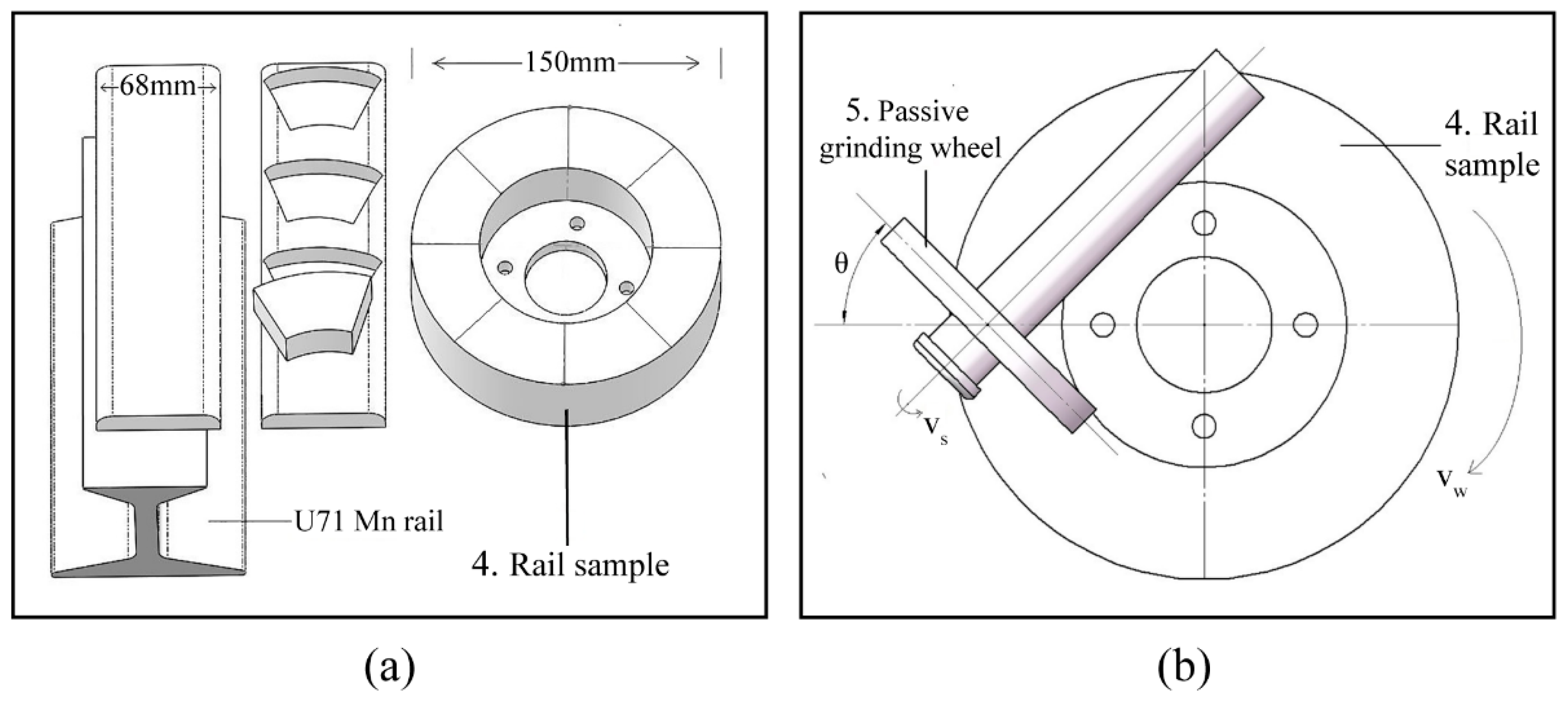
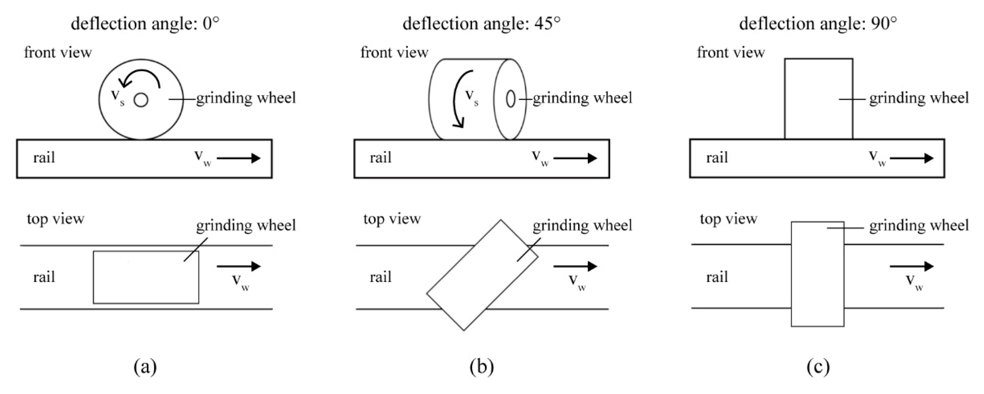
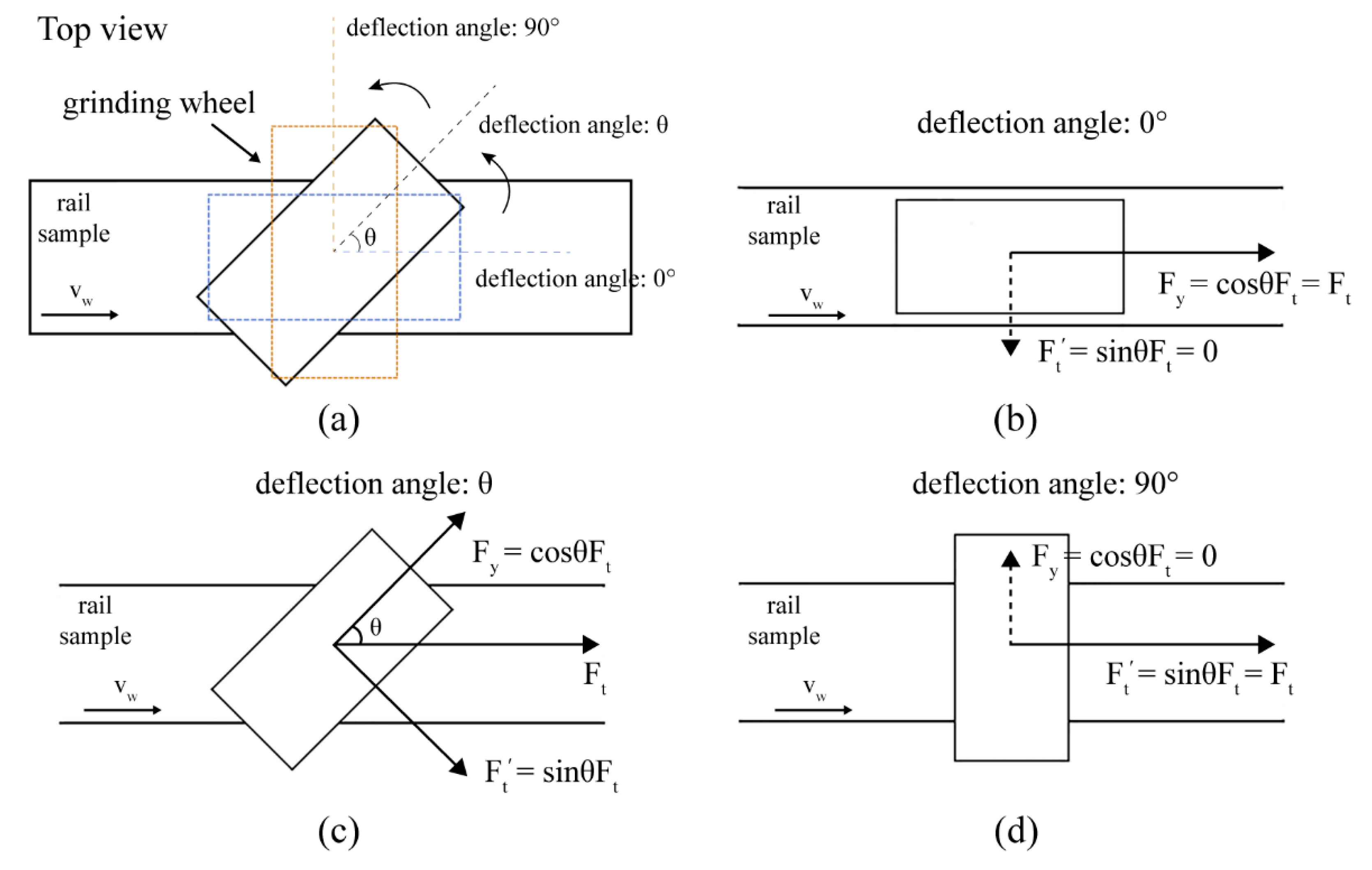
4.1. Effect of Deflection Angle on Passive Grinding Process

To ensure that the passive grinding test machine can perform a passive grinding process, the tester is designed to be able to adjust the grinding angle. The grinding wheel can be deflected in the angle range of 0° to 90°. The angle of 90° to 180° is the same with 0° to 90° as the grinding principle, only in the opposite direction. The grinding wheels show different motion states in the passive grinding machine at different deflection angles. Taking the limit and intermediate values as examples, as the deflection angle is 0°, 45°, and 90°, respectively, the passive grinding state of the grinding wheel on the rail is presented in Figure 7. The vs. is the linear velocity of the grinding wheel and the vw is the relative movement speed of the sample and the grinding wheel. When the deflection angle is 0°, the grinding wheel is just rolling on the rail sample and does not produce grinding behavior. As the deflection angle increases, the grinding wheel passively grinds the rail sample in addition to rolling, whereas, when the deflection angle is increased to 90°, the grinding wheel does not rotate and only behaves as slip grinding on the rail sample. The effect of deflection angle on the passive grinding process can be explained by the grinding force analysis.
Since the forces are mutual, the force analysis of grinding wheels with different deflection angles can illustrate the passive grinding process, as shown in Figure 8. Where Ft (N) is the total grinding force on the grinding wheel, which can be decomposed into Fy (N) and Ft′ (N) at a deflection angle of θ (°), as shown in Equation (4).
F t = F y 2 + F t 2 = cos 2 θ F t + sin 2 θ F t
In the formula, Fy (N) is the tangential force along with the grinding wheel, which is the driving force to rotate the wheel; Ft′ (N) is the force along the axial direction of the grinding wheel, which is the cutting force. When the deflection angle is 0°, the driving force (Fy) on the grinding wheel is equal to the total grinding force (Ft), while the cutting force (Ft) is 0 (Figure 8b). Thus, the passive grinding process is simply rotating the grinding wheel without grinding removal. When the deflection angle (θ) increases, the driving force (Fy) on the grinding wheel decreases while the cutting force (Ft’) increases (Figure 8c). As the deflection angle of the grinding wheel increases, when the deflection angle reaches 90°, the driving force (Fv) decreases to 0 (Figure 8d). At this point, the grinding force (Ft) on the wheel is fully converted into the cutting force (Ft) and the behavior of the grinding wheel on the workpiece is changed from grinding to sliding and cutting. Therefore, to balance the rotation and grinding of the grinding wheel, a deflection angle of 45° is the most appropriate. In the future study, we will set up several groups of grinding variables for experiments to further discuss the effect of deflection angle on the passive grinding process in more detail from the grinding efficiency, grinding wheel consumption, grinding force, grinding temperature, and grinding quality.

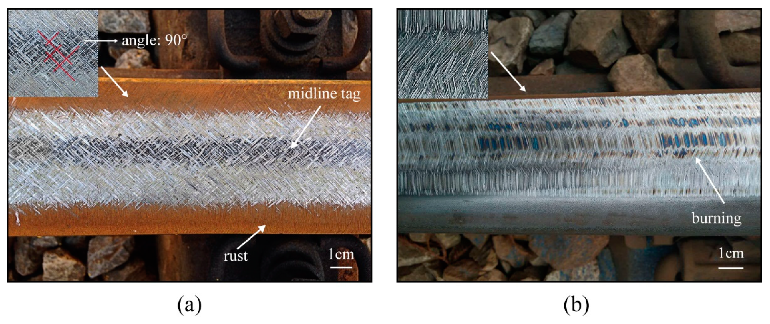
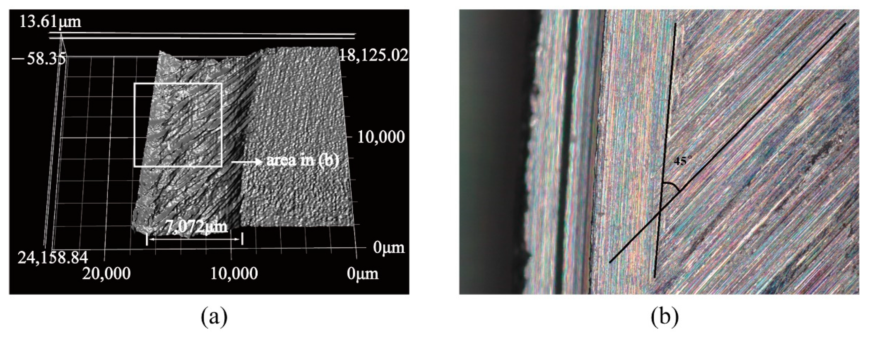
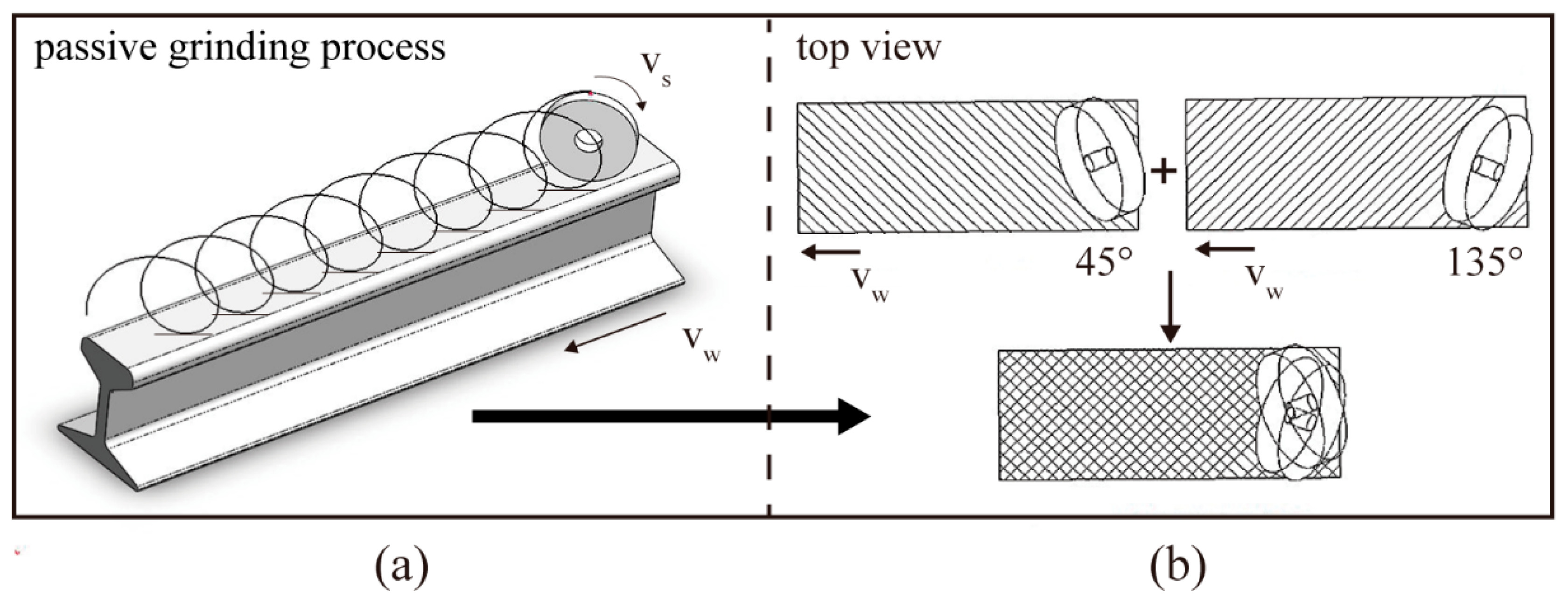
4.2. Characteristics of the Grinding Marks

The surface morphology of the rails after passive and active grinding is significantly different, as shown in Figure 9. The location of the rail grinding test in the figure is the Yujiahu railway section in Xiangyang, Hubei, China. Figure 9a is the surface topography of the rail after grinding by HSG (test type) rail high-speed passive grinding train, and Figure 9b is the surface topography of the rail after grinding by GMC-96x rail active grinding train. The grinding marks of passive grinding have distinctive morphological characteristics. Since the selected grinding angle for passive grinding on the railway line is 45°, the included angle of the grinding marks is 90°. These grinding marks are crossed and the directions are perpendicular to each other. The grinding wheels are usually divided into two equal parts and placed crosswise on the rail at a deflection angle of 45° and 135° in the actual passive grinding process, as shown in Figure 1b. The arrangement of the grinding wheels makes the grinding marks on the rail surface angled and cross each other.
The unique grinding morphology of passive grinding is related to the grinding behavior of the grinding wheel in the passive grinding process. Selecting an abrasive on the passive grinding wheel, and its motion trajectory is shown in Figure 10a. It can be found that the trajectory line of passive grinding is spiral. When numerous spiral lines produced by the grinding wheels in both directions overlap each other, the passive grinding marks on the rail surface form the decussation, as shown in Figure 10b. It results in the production of two vertical grinding marks in two directions and forms the decussate surface topography.
The deflection angle of the grinding wheel on the passive grinding test machine was set to 45° to simulate the passive grinding process for the test, and the surface topography of the rail specimens after grinding is shown in Figure 11. The grinding characteristics of the rail sample are consistent with those of the rail after passive grinding. The difference is that there are no intersecting grinding marks. This is because the grinding tester was designed with only one grinding wheel to control the variables of the passive grinding test. The passive grinding test machine can also be equipped with multiple sets of symmetrical passive grinding wheels so that the rail surface topography can be obtained with the same morphology as the rail grinding site, which has intersecting grinding marks. Moreover, the width of the passive grinding wheel used in the passive grinding test is 10 mm. Measuring the surface of the rail sample after the passive grinding test shows that the grinding width on the sample is about 7.072 mm and the angle between the grinding marks and the horizontal line is 45°. It can be calculated that the length of the grinding marks is basically equal to 10 mm, which indicates that the grinding behavior and grinding process of the passive grinding wheel are almost the same as the actual passive grinding. These all conform to the passive grinding principle and prove the feasibility of the passive grinding test machine.

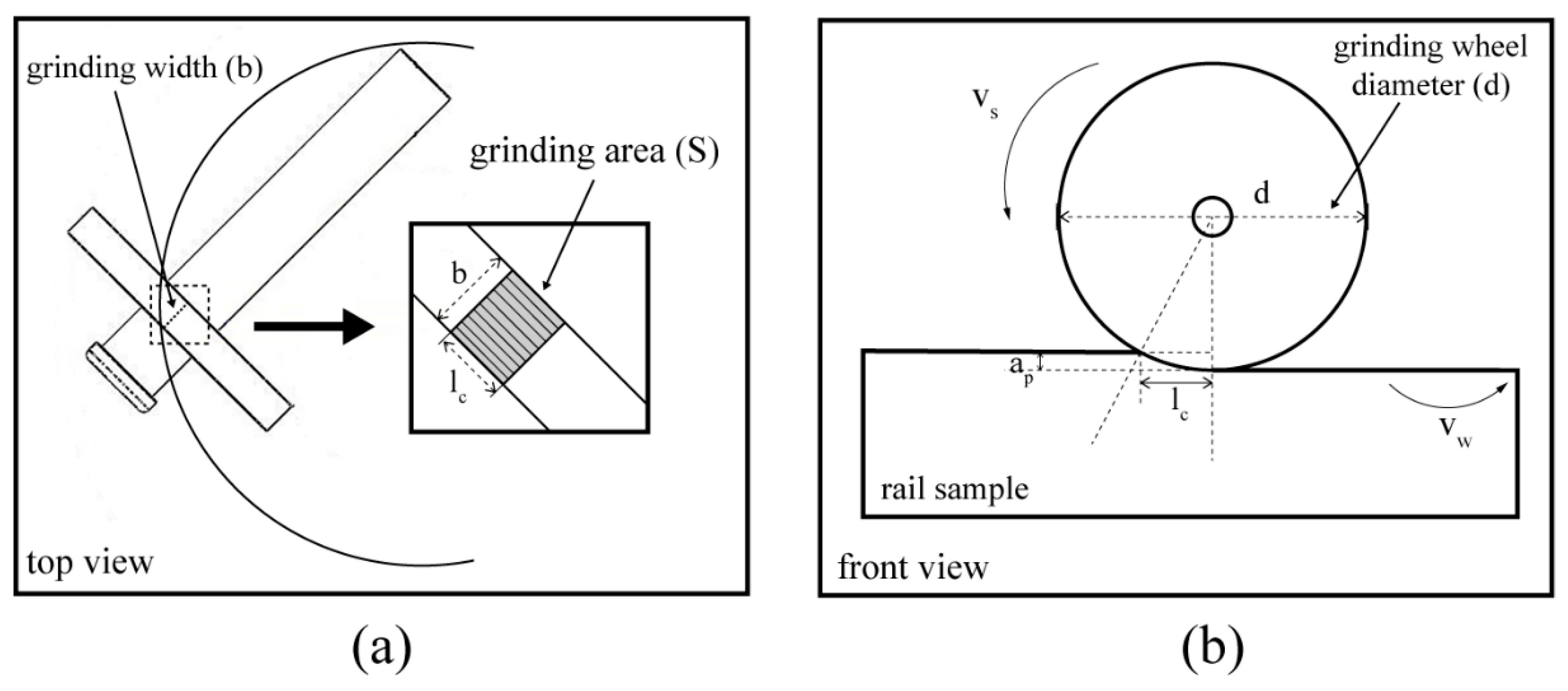
4.3. Grinding Pressure for the Test Machine

Passive grinding is a grinding process of constant pressure grinding. The grinding pressure is one of the key factors in passive grinding [36]. Under different grinding pressure, not only the surface topographies after passive grinding is significantly diverse, but also the performance of the grinding wheel is affected [22]. The pressure load of the passive grinding machine can be changed by adjusting the pressure of the cylinder, which provides experimental conditions for investigating the influence of the grinding pressure on the passive grinding process and the passive grinding wheel.
Moreover, the passive grinding machine can reproduce the grinding pressure parameters of other large passive grinding equipment by adjusting the grinding pressure load to simulate the passive grinding process. This is achieved by the equivalent pressure. To achieve the same grinding effect, although the grinding pressure load required in the passive grinding process varies depending on the size of the workpiece and the grinding wheel, the pressure required per unit area is the same. Therefore, the grinding pressure load required for the passive grinding process can be converted by the equivalent pressure, as shown in Equation (5).
P = F 1 S 1 = F 2 S 2
In the formula, P (MPa) is the pressure, F1 (N) is the grinding pressure load of other equipment, F2 (N) is the grinding pressure load of the passive grinding tester, S1 (mm2) is the contact area between the grinding wheel and the workpiece in other equipment, and S2 (mm2) is the contact area between the grinding wheel and the workpiece in the passive grinding tester. It can be seen that the change of the grinding pressure load is related to the grinding contact area between the grinding wheel and the workpiece. The passive grinding wheel is a micro-elastic composite material [37]. If the contact length between the grinding wheel and the workpiece is regarded as a straight line, the contact area between the grinding wheel and the workpiece in the grinding process is shown in Figure 12a. The grinding contact area can be obtained through the size of the grinding wheel. As shown in Figure 12b, passive grinding belongs to a special way of surface grinding, which will keep the feed amount and feed speed largely steady at a constant grinding pressure. Thus, the equivalent diameter of the grinding wheel is approximately equal to the diameter of the grinding wheel, which makes the contact length between the grinding wheel and the workpiece approximately equal to the geometrical contact length (lc) [38]. The contact area S (mm2) between the grinding wheel and the workpiece can be obtained by Equation (6) [39].
S = b · l c = b · a p · d
In the formula, b (mm) is the grinding width, lc (mm) is the geometrical contact length between the grinding wheel and the workpiece, ap (mm) is the grinding depth, and d (mm) is the diameter of the grinding wheel. To ensure the same grinding effect, the grinding depth also needs to be consistent. Therefore, the grinding pressure load required to simulate different passive grinding processes can be converted from the size of the passive grinding wheel.

5. Conclusions

This study designed a passive grinding simulation test machine based on the principle of rail passive grinding. The grinding tester provides a test method and test equipment for the study of passive grinding. The main conclusions are as follows:
  • The passive grinding machine simulates the passive grinding process through the relative movement between the grinding wheel and the sample generated by the sample rotation. Additionally, it is equipped with the force and temperature measuring device to monitor the grinding process.
  • The deflection angle affects the passive grinding process. The analysis concluded that a deflection angle of 45° is reasonable for passive grinding.
  • The characteristics of grinding marks on the surface of the rail sample after passive grinding are consistent with those of the rail passive grinding online, which shows the feasibility of the passive grinding tester to simulate the passive grinding behavior and process.
  • The passive grinding machine can convert the grinding pressure load by the size of the grinding wheel to simulate the pressure parameters of the actual passive grinding conditions to achieve the same grinding effect.
  • With the designed passive grinding test machine, grinding tests can be used to investigate the effects of grinding wheel deflection angle, relative motion speed, grinding pressure, and grinding time on the passive grinding process in future studies. In addition, the simulation test of passive grinding can be used to study the grinding performance of passive grinding wheels of different structures and materials on rails.

Author Contributions

P.-Z.L.: Validation, methodology, visualization, investigation, data curation, writing—original draft. W.-J.Z. and J.P.: Resources, funding acquisition, project administration. X.-D.S.: Formal analysis. F.-R.X.: Conceptualization, supervision, review and editing. All authors have read and agreed to the published version of the manuscript.

Funding

This research was funded by Science and Technology Department of Henan Province, grant number No. 181200212000. The study did not involve humans or animals.

Institutional Review Board Statement

Not applicable.

Informed Consent Statement

Not applicable.

Data Availability Statement

The datasets used or analyzed during the current study are available from the corresponding author on reasonable request.

Conflicts of Interest

The authors declare that they have no known competing financial interest or personal relationships that could have appeared to influence the work reported in this paper.

References

  1. Calzada-Infante, L.; Adenso-Díaz, B.; García Carbajal, S. Analysis of the European international railway network and passenger transfers. Chaos Solitons Fractals 2020, 141, 110357. [Google Scholar] [CrossRef]
  2. Peetawan, W.; Suthiwartnarueput, K. Identifying factors affecting the success of rail infrastructure development projects contributing to a logistics platform: A Thailand case study. Kasetsart J. Soc. Sci. 2018, 39, 320–327. [Google Scholar] [CrossRef]
  3. Krishna, V.V.; Hossein-Nia, S.; Casanueva, C.; Stichel, S. Long term rail surface damage considering maintenance interventions. Wear 2020, 460–461, 203462. [Google Scholar] [CrossRef]
  4. Shen, C.; Deng, X.; Wei, Z.; Dollevoet, R.; Li, Z. Comparisons between beam and continuum models for modelling wheel-rail impact at a singular rail surface defect. Int. J. Mech. Sci. 2021, 198, 106400. [Google Scholar] [CrossRef]
  5. Ma, L.; Guo, J.; Liu, Q.Y.; Wang, W.J. Fatigue crack growth and damage characteristics of high-speed rail at low ambient temperature. Eng. Fail. Anal. 2017, 82, 802–815. [Google Scholar] [CrossRef]
  6. Markine, V.L.; Steenbergen, M.; Shevtsov, I.Y. Combatting RCF on switch points by tuning elastic track properties. Wear 2011, 271, 158–167. [Google Scholar] [CrossRef]
  7. Markine, V.L.; Liu, X.; Mashal, A.A.; Ma, Y. Analysis and improvement of railway crossing performance using numerical and experimental approach: Application to 1: 9 double crossovers. In The Dynamics of Vehicles on Roads and Tracks; CRC Press: Boca Raton, FL, USA, 2018; pp. 717–722. [Google Scholar]
  8. Kampczyk, A. Geodezyjno-analityczne opracowanie projektów połączeń torowych. Cz. 1. Przegld Geodezyjny 2010, 82, 3–8. [Google Scholar]
  9. Kampczyk, A. Toromierz DTGi torów w Transporcie Szynowym. Magazyn Geoinformacyjny; GEODETA Sp. z o. o: Gorzów Wielkopolski, Poland, 2009; Volume 12. (In Dutch) [Google Scholar]
  10. Dindar, S.; Kaewunruen, S.; An, M. Identification of appropriate risk analysis techniques for railway turnout systems. J. Risk Res. 2018, 21, 974–995. [Google Scholar] [CrossRef]
  11. Dindar, S.; Kaewunruen, S.; An, M. Rail accident analysis using large-scale investigations of train derailments on switches and crossings: Comparing the performances of a novel stochastic mathematical prediction and various assumptions. Eng. Fail. Anal. 2019, 103, 203–216. [Google Scholar] [CrossRef]
  12. Zhang, S.; Zhou, K.; Ding, H.; Guo, J.; Liu, Q.; Wang, W. Effects of Grinding Passes and Direction on Material Removal Behaviours in the Rail Grinding Process. Materials 2018, 11, 2293. [Google Scholar] [CrossRef] [PubMed] [Green Version]
  13. Singleton, R.; Marshall, M.B.; Lewis, R.; Evans, G. Rail grinding for the 21st century—Taking a lead from the aerospace industry. Proc. Inst. Mech. Eng. Part F J. Rail Rapid Transit 2014, 229, 457–465. [Google Scholar] [CrossRef] [Green Version]
  14. Cuervo, P.A.; Santa, J.F.; Toro, A. Correlations between wear mechanisms and rail grinding operations in a commercial railroad. Tribol. Int. 2015, 82, 265–273. [Google Scholar] [CrossRef]
  15. Zhao, C.Y.; Li, J.Y.; Wang, W.X. Forming mechanisms based simulation and prediction of grinding surface roughness for abrasive belt rail grinding. Procedia CIRP 2020, 87, 503–508. [Google Scholar] [CrossRef]
  16. Zhou, K.; Ding, H.H.; Wang, W.J.; Wang, R.X.; Guo, J.; Liu, Q.Y. Influence of grinding pressure on removal behaviours of rail material. Tribol. Int. 2019, 134, 417–426. [Google Scholar] [CrossRef]
  17. Zhou, K.; Ding, H.; Wang, R.; Yang, J.; Guo, J.; Liu, Q.; Wang, W. Experimental investigation on material removal mechanism during rail grinding at different forward speeds. Tribol. Int. 2020, 143, 106040. [Google Scholar] [CrossRef]
  18. Fang, H.; Su, Y.; Du, X.; Wang, F.; Li, B. Experimental and Numerical Investigation on Repairing Effect of Polymer Grouting for Settlement of High-Speed Railway Unballasted Track. Appl. Sci. 2019, 9, 4496. [Google Scholar] [CrossRef] [Green Version]
  19. Satoh, Y.; Iwafuchi, K. Effect of rail grinding on rolling contact fatigue in railway rail used in conventional line in Japan. Wear 2008, 265, 1342–1348. [Google Scholar] [CrossRef]
  20. Gustavsson, E.; Patriksson, M.; Strmberg, A.-B.; Wojciechowski, A.; Önnheim, M. Preventive maintenance scheduling of multi-component systems with interval costs. Comput. Ind. Eng. 2014, 76, 390–400. [Google Scholar] [CrossRef] [Green Version]
  21. Neto, A.C.; Diest, K.V.; Ferrarotti, G.; Kik, W. Wear Analysis of the High-Speed-Grinding Vehicle HSG-2: Validation, Simulation and Comparison with Measurements. In Dynamics of Vehicles on Roads and Tracks, Proceedings of the 25th International Symposium on Dynamics of Vehicles on Roads and Tracks (IAVSD 2017), Rockhampton, Australia, 14–18 August 2017; CRC Press: Boca Raton, FL, USA, 2018. [Google Scholar]
  22. Liu, P.-Z.; Zou, W.-J.; Peng, J.; Song, X.-D.; Xiao, F.-R. Study on the Effect of Grinding Pressure on Material Removal Behavior Performed on a Self-Designed Passive Grinding Simulator. Appl. Sci. 2021, 11, 4128. [Google Scholar] [CrossRef]
  23. Reddy, V.; Chattopadhyay, G.; Larsson-Kraik, P.O.; Hargreaves, D.J. Modelling and analysis of rail maintenance cost. Int. J. Prod. Econ. 2007, 105, 475–482. [Google Scholar] [CrossRef]
  24. Mesaritis, M.; Shamsa, M.; Cuervo, P.; Santa, J.F.; Toro, A.; Marshall, M.B.; Lewis, R. A laboratory demonstration of rail grinding and analysis of running roughness and wear. Wear 2020, 456–457, 203379. [Google Scholar] [CrossRef]
  25. Wu, H.; Xiao, B.; Xiao, H.; Zhang, Y.; Dou, L. Study on wear characteristics of brazed diamond sheet for rail’s composite grinding wheel under different pressures. Wear 2019, 424–425, 183–192. [Google Scholar] [CrossRef]
  26. Uhlmann, E.; Lypovka, P.; Hochschild, L.; Schröer, N. Influence of rail grinding process parameters on rail surface roughness and surface layer hardness. Wear 2016, 366–367, 287–293. [Google Scholar] [CrossRef]
  27. Zhe, H.; Li, J.; Liu, Y.; Meng, N.; Fan, W. Investigating the effects of contact pressure on rail material abrasive belt grinding performance. Int. J. Adv. Manuf. Technol. 2017, 93, 779–786. [Google Scholar] [CrossRef]
  28. Gu, K.K.; Lin, Q.; Wang, W.J.; Wang, H.Y.; Guo, J.; Liu, Q.Y.; Zhu, M.H. Analysis on the effects of rotational speed of grinding stone on removal behavior of rail material. Wear 2015, 342–343, 52–59. [Google Scholar] [CrossRef]
  29. Pereverzev, P.P.; Pimenov, D.Y. A grinding force model allowing for dulling of abrasive wheel cutting grains in plunge cylindrical grinding. J. Frict. Wear 2016, 37, 60–65. [Google Scholar] [CrossRef]
  30. Von Diest, K. High Speed Grinding: Evolution einer etablierten Technik. Senbahntechnische Rundsch. 2015, 64, 54–57. [Google Scholar]
  31. Lin, B.; Zhou, K.; Guo, J.; Liu, Q.Y.; Wang, W.J. Influence of grinding parameters on surface temperature and burn behaviors of grinding rail. Tribol. Int. 2018, 122, 151–162. [Google Scholar] [CrossRef]
  32. Wang, W.J.; Gu, K.K.; Zhou, K.; Cai, Z.B.; Guo, J.; Liu, Q.Y. Influence of granularity of grinding stone on grinding force and material removal in the rail grinding process. Arch. Proc. Inst. Mech. Eng. Part J J. Eng. Tribol. 2019, 233, 355–365. [Google Scholar] [CrossRef]
  33. Zhang, P.; Zhang, W.; Yuan, Y.; Fan, X.; Zhu, M. Probing the effect of grinding-heat on material removal mechanism of rail grinding. Tribol. Int. 2020, 147, 105942. [Google Scholar] [CrossRef]
  34. Kuriyagawa, T.; Syoji, K.; Ohshita, H. Grinding temperature within contact arc between wheel and workpiece in high-efficiency grinding of ultrahard cutting tool materials. J. Mater. Process. Technol. 2003, 136, 39–47. [Google Scholar] [CrossRef]
  35. Qian, N.; Fu, Y.; Chen, J.; Khan, A.M.; Xu, J. Axial rotating heat-pipe grinding wheel for eco-benign machining: A novel method for dry profile-grinding of Ti-6Al-4V alloy. J. Manuf. Process. 2020, 56, 216–227. [Google Scholar] [CrossRef]
  36. Von Diest, K.; Meyer, R. German turnouts get the high-speed grinding treatment. Int. Railw. J. 2016, 56, 36–38. [Google Scholar]
  37. Yuan, Y.; Zhang, W.; Zhang, P.; Fan, X.; Zhu, M. Porous grinding wheels toward alleviating the pre-fatigue and increasing the material removal efficiency for rail grinding. Tribol. Int. 2021, 154, 106692. [Google Scholar] [CrossRef]
  38. Malkin, S. Grinding Technology: Theory and Applications of Machining with Abrasives; SME: Southfield, MI, USA, 1989. [Google Scholar]
  39. Osa, J.L.; Sánchez, J.A.; Ortega, N.; Iordanoff, I.; Charles, J.L. Discrete-element modelling of the grinding contact length combining the wheel-body structure and the surface-topography models. Int. J. Mach. Tools Manuf. 2016, 110, 43–54. [Google Scholar] [CrossRef] [Green Version]
Figure 1. Rail grinding machine, (a) active grinding, (b) passive grinding.
Processes 09 01317 g001
Figure 2. Schematic diagram of grinding process, (a) active grinding, (b) passive grinding.
Processes 09 01317 g002
Figure 3. Structure of the passive grinding test machine, (a) overall structure, (b) structure of grinding.
Processes 09 01317 g003
Figure 4. (a) Preparation and morphology of rail sample, (b) passive grinding process.
Processes 09 01317 g004
Figure 5. Labview program of force measurement system.
Processes 09 01317 g005
Figure 6. Structure of the temperature measurement system.
Processes 09 01317 g006
Figure 7. Passive grinding process under different deflection angles, (a) 0°, (b) 45°, (c) 90°.
Processes 09 01317 g007
Figure 8. Top view of force analysis of passive grinding wheel under different deflection angles, (a) range of deflection angle, (b) deflection angle is 0°, (c) deflection angle is θ, (d) deflection angle is 90°.
Processes 09 01317 g008
Figure 9. Rail surface topography, (a) after passive grinding, (b) after active grinding.
Processes 09 01317 g009
Figure 10. (a) Motion trajectory of grinding wheel in passive grinding process, (b) grinding marks of passive grinding.
Processes 09 01317 g010
Figure 11. (a) Three-dimensional profile of grinding marks on the rail sample surface, (b) the angle between the grinding marks and the grinding direction.
Processes 09 01317 g011
Figure 12. Grinding contact process between the grinding wheel and the workpiece, (a) top view, (b) front view.
Processes 09 01317 g012
Publisher’s Note: MDPI stays neutral with regard to jurisdictional claims in published maps and institutional affiliations.

