Article

Biolubricant Production through Double Transesterification: Reactor Design for the Implementation of a Biorefinery Based on Rapeseed

by
José María Encinar
,
Sergio Nogales-Delgado
* and
Antonio Pinilla
Department of Chemical Engineering and Physical-Chemistry, University of Extremadura, Avda. De Elvas s/n, 06006 Badajoz, Spain
*
Author to whom correspondence should be addressed.
Processes 2021, 9(7), 1224; https://doi.org/10.3390/pr9071224
Submission received: 31 May 2021 / Revised: 12 July 2021 / Accepted: 13 July 2021 / Published: 15 July 2021

Abstract

:
The production and use of biolubricants as replacements for mineral lubricants align with the promotion of sustainable development goals, contributing to the sustainable economic growth of developing countries as well as the preservation of the environment. The implementation of biorefineries (where the production of biolubricants through transesterification could play an important role) is becoming important for these purposes, using natural feedstocks such as rapeseed, which is an interesting crop that can adapt to different climates under extreme weather conditions. The aim of this research work was to study the design of a reactor to produce rapeseed biolubricant through double transesterification of the corresponding vegetable oil. Thus, the kinetics to design a reactor was studied, sizing it according to the properties of the biolubricant and the demand in Spain. As a result, a SAE 10W30 biolubricant was obtained, which was suitable for Diesel engines. A batch reactor was selected for the production of this biolubricant at a national level, with a pseudo-first reaction order and a reactor volume of 9.66 m3.

1. Introduction

A biolubricant is a lubricant that is neither detrimental to health nor harmful to the environment. Their main advantages, compared to the use of conventional lubricants, are their adaptation to green chemistry, biodegradability, sustainability and compliance with current legislation and customers’ needs, focused on environmentally friendly products [1]. Apart from that, other physical properties that are improved compared to mineral lubricants are: better lubricity, higher flash and combustion points, or higher viscosity index, among others. However, there are some disadvantages such as their lower oxidative stability and cold flow properties [2]. Nevertheless, the use of additives like antioxidants can improve the performance of this product [3].
The main raw materials for biolubricant production are vegetable oils, such as rapeseed, sunflower, soybean, safflower, etc., which are mainly composed of triglycerides. In that sense, rapeseed is an interesting oil crop, as it is resistant to cold and hot climates in drylands, having short vegetation periods and a fatty acid composition that is suitable for food use, among others. Moreover, one interesting characteristic of this crop is its long tap root, which makes it suitable to take part in crop rotations [4]. Finally, its high oleic acid content (with one single double bond, which makes it less prone to oxidation compared to linoleic or linolenic acid) could contribute to the stability of the final products obtained through transesterification, such as biodiesel or biolubricants. Indeed, the influence of the raw material on these products has been widely studied in the literature, presenting different viscosity or oxidative stability values depending on the fatty acid profile [5,6].
There are several processes to obtain products (from vegetable oils) that can be used as biolubricants, such as selective hydrogenation, estolide formation, epoxidation or double transesterification [3,7]. Concerning epoxidation, consisting of the interconnection of unsaturated C–C bonds by an oxygen atom (at low reaction temperatures), the biolubricants obtained presented better lubricity and thermo-oxidative stability. However, pour point increased, whereas viscosity index was reduced. Regarding transesterification, it is the reaction of an ester and an alcohol to produce another ester through alkyl group exchange. Normally, the biolubricants obtained have good low temperature properties and high thermo-oxidative stability, whereas high reaction temperatures are required [3]. Figure 1 shows this process. As it can be seen, the first transesterification implies the use of triglycerides and methanol to produce fatty acid methyl esters (FAMEs, biodiesel) and glycerol. For the second transesterification, FAMEs react with a superior alcohol to produce the corresponding ester, releasing methanol.
As a consequence, double transesterification could provide plenty of products and by-products that can be valuable during biolubricant production. The whole process shows a high atom economy, as most by-products can be re-used in this same process or valued for market purposes, which is a considerable advantage. In that manner, there are many positive aspects in this process that can be suitable for the implementation of biorefineries [8]:
  • Use of natural and renewable sources.
  • Production of valuable products (like biodiesel and biolubricant).
  • Generation of exploitable by-products (such as glycerol, with a wide range of uses depending on its purity [9]).
  • Reutilization of by-products (like methanol).
This way, biorefineries can contribute to the economic growth of many developing countries or less-industrialized areas. In that sense, the Extremadura region is a traditionally agricultural area in Spain, which can profit from circular economy and current environmental policies, where the installation of biorefineries can perfectly fit, as pointed out in previous studies [10].
However, the implementation of biorefineries might be a challenge, as many factors have to be taken into account, such as raw materials, technologies, processing routes, products, and technical, economic or environmental aspects [8]. This way, the design of different components for biorefineries can help assess the feasibility of the implementation of these facilities. As far as we know, few specific studies have been carried out in order to prove the feasibility of biorefinery implementation based on vegetable oils through the design of its components (such as reactors), determining the kinetics and production for a certain area or region depending on the consumption of the products obtained.
The aim of this study was to assess the role of rapeseed oil as a starting point for a biorefinery, focusing on biolubricant production through double transesterification. Thus, the kinetics of the second transesterification as well as the reactor design and sizing (according to a specific production of the final biolubricant) were carried out.

2. Materials and Methods

2.1. Biodiesel and Biolubricant Production

Rapeseed oil was produced in CICYTEX (Centro de Investigaciones Científicas y Tecnológicas de Extremadura) by the Department of Energy and Extensive Crops. The oil had high-quality parameters such as low free fatty acid content (<1%), only requiring filtration after mechanical extraction. Afterwards, the oil was stored in 25-L opaque containers for further treatments and analysis.
Rapeseed biolubricant was obtained through double transesterification with different alcohols. Thus, the steps were the following (see Table 1 for the main chemical conditions):
  • First transesterification with methanol. For fatty acid methyl ester production (biodiesel), the chemical conditions were based on previous studies [11].
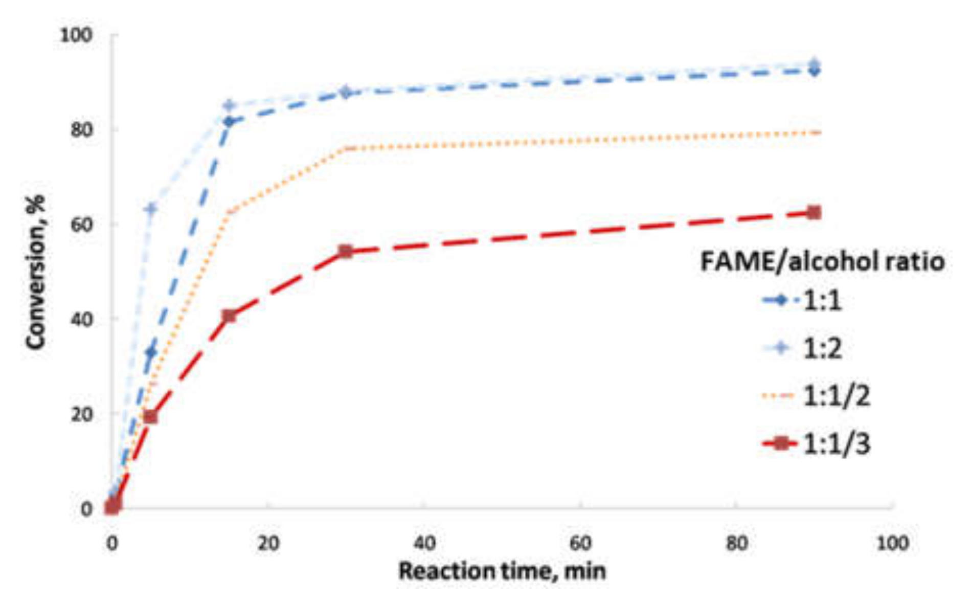
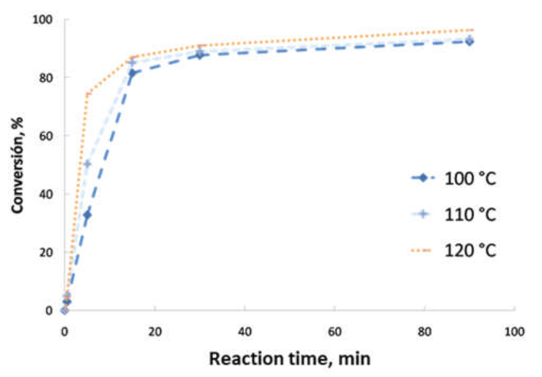
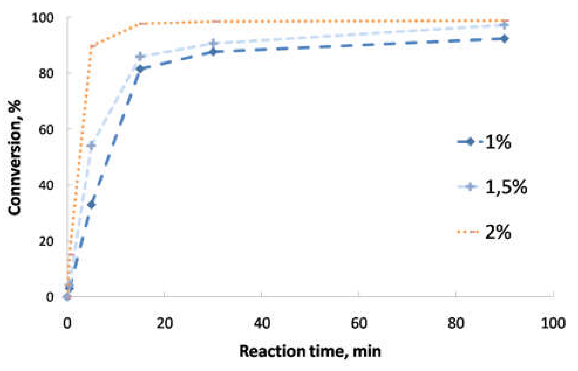
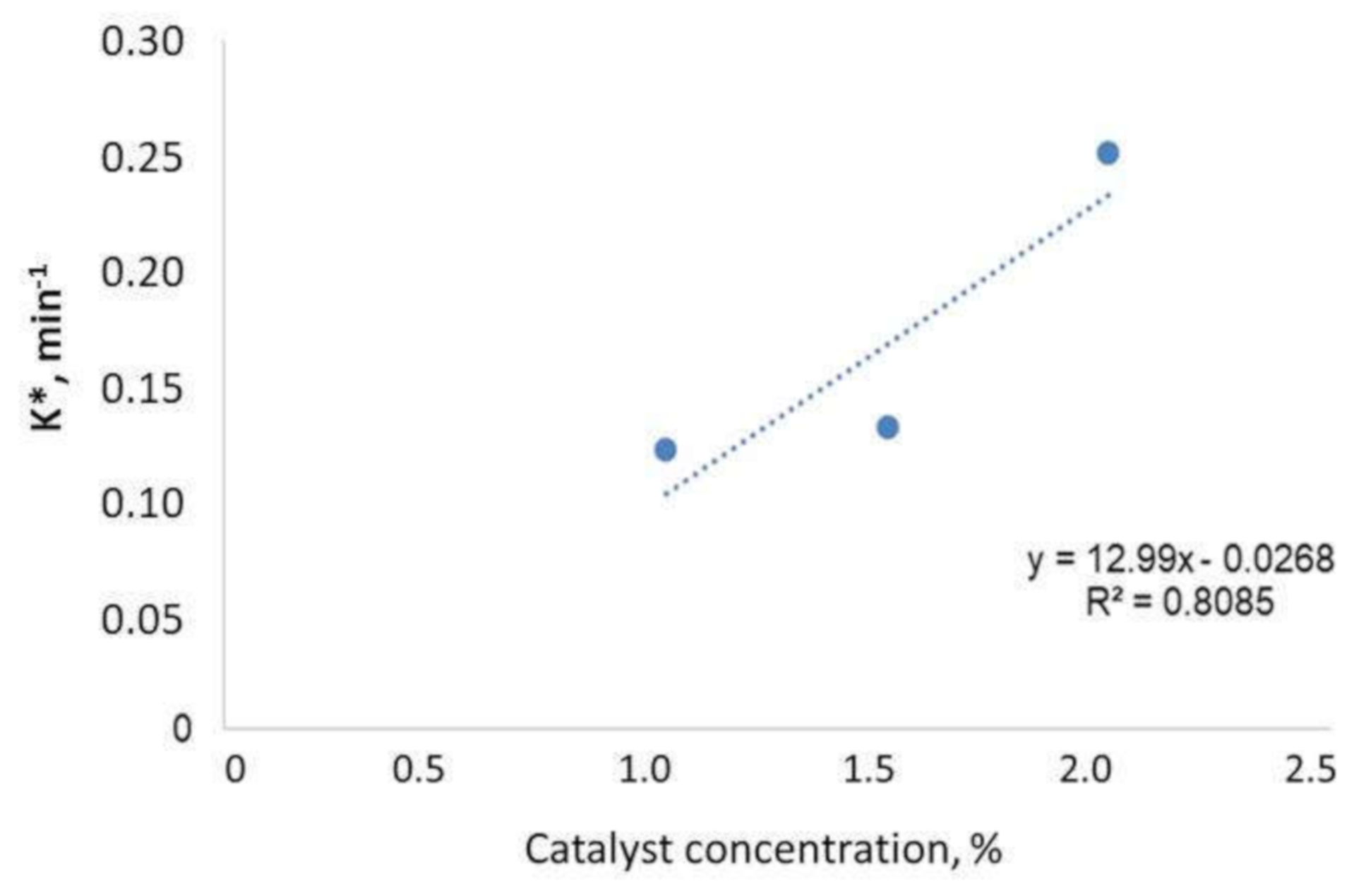
  • Second transesterification with 2-ethyl-2-hydroxymethyl-1,3-propanediol (Sigma-Aldrich, Saint Louis, MO, USA; solid state; molar mass, 134.18 g·mol−1; density, 1.08 g·cm−3; melting point, 56–58 °C; vapor pressure, 67 hPa at 200 °C; flash and combustion points, 180 and 367 °C, respectively). The biolubricant production was optimized in order to obtain high yields, exceeding 95%. For that purpose, experimental sets at different FAME/alcohol ratios (1:1/3; 1:1/2, 1:1 and 1:2), temperatures (100, 110 and 120 °C) and catalyst concentrations (1.0, 1.5 and 2.0% w/w) were carried out. These experiments were also used for the kinetic determination and reactor design. Once the reaction took place, the sample was purified by vacuum filtration, separating the surplus alcohol.

2.2. Biodiesel and Biolubricant Characterization

Both biodiesel and biolubricant were characterized according to the UNE-EN 14,214 standard [12], as explained in previous studies [2,11,13]. Density was determined by using a pycnometer, correcting the value at 15 °C. Viscosity was measured by using Ostwald’s viscometer at 40 and 100 °C, obtaining with these data the viscosity index. Flash and combustion points were obtained through the open-cup Cleveland method. Moisture was determined by using a Metrohm 870 KF Trinitro Plus (Metrohm, Herisau, Switzerland). Acid and iodine numbers were determined following the corresponding volumetric determination, according to the standard and cold filter plugging point (CFPP) was obtained (when necessary) for the samples obtained [13,14,15]. Regarding the yield of the reactions and fatty acid methyl ester profile of biodiesel, gas chromatography was used, following the conditions explained elsewhere [16]. Thus, the yield of the biolubricant was obtained by the decrease in FAMEs. Equally, the reaction evolution was also assessed by FAME decrease. Finally, oxidative stability was calculated through the Rancimat method, obtaining the induction point (expressed in hours) [17].

2.3. Kinetic Study and Volume Reactor Determination

In order to design a reactor for biolubricant production from biodiesel, different factors were taken into account, as follows:
  • Characterization of the biolubricant, which determines its use in industry, paying special attention to viscosity at 40 and 100 °C and viscosity index and comparing with traditional lubricants.
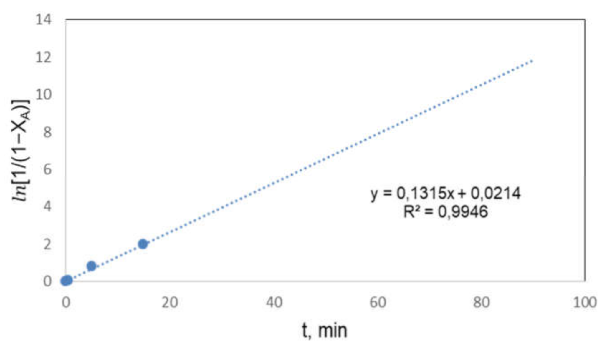
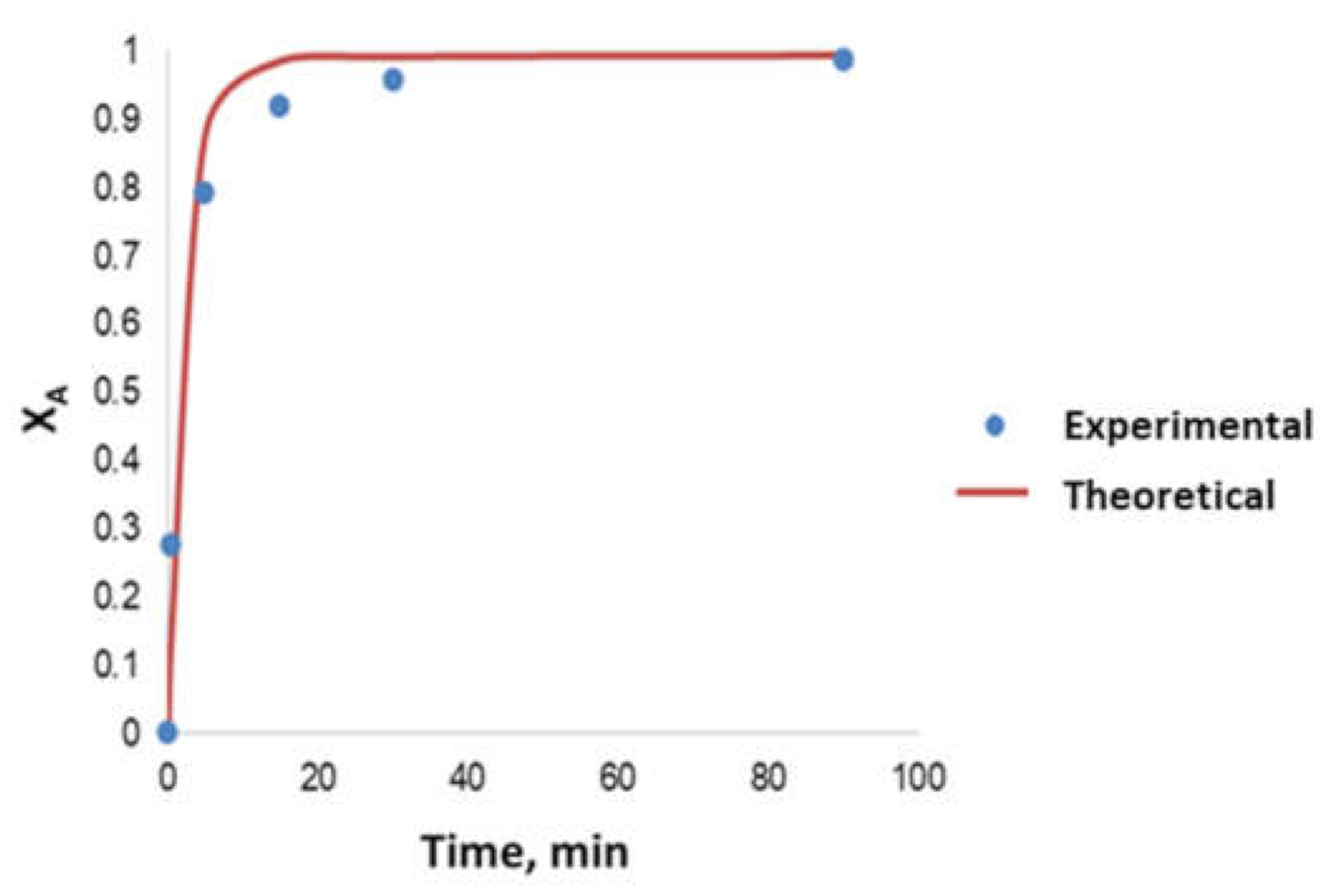
  • Determination of the order of reaction of the second transesterification process, obtaining the main kinetic parameters. For that purpose, the decrease in FAMEs from biodiesel to biolubricant production at different reaction times (0, 5, 15, 25 and 90 min) was measured to determine the reaction evolution. Different parameters like temperature and catalyst addition were studied.
  • Calculation of biolubricant production at a national level (in this case, Spain), comparing with the equivalent lubricant production at the same level.
  • Selection of the suitable reactor depending on production, obtaining the design equation by a mass balance.
  • Reactor volume determination.

3. Results and Discussion

3.1. Biodiesel Characterization

First, a characterization of the biodiesel used as a starting point for biolubricant production was carried out. As it can be observed in Table 2, this biofuel complied with almost all the parameters established in the UNE-EN 14,214 standard, except for the oxidative stability. Thus, the chemical conditions were suitable to obtain a high-yield product, showing a high flash point, which implies safety during its storage.
Regarding FAME content of biodiesel, the main components were methyl oleate (66.4%), linoleate (16.6%), linolenate (9.1%) and palmitate (3.8%). The higher content in methyl oleate, which is a mono-unsaturated compound, could explain the higher oxidative stability compared to other biodiesel samples found in the literature, needing lower amounts of antioxidant additives to comply with the standard [18,19,20].

3.2. Reaction Optimization

Concerning the optimization of the second transesterification reaction, Figure 2, Figure 3 and Figure 4 show the different conversion evolution depending on the different parameter changes (FAME/2-ethyl-2-hydroxymethyl-1,3-propanediol ratio; temperature and catalyst concentration, respectively). In the case of FAME/alcohol ratio, Figure 2 shows the main results, obtaining similar yields for 1:1 and 1:2 ratios. As the amount of alcohol increased, the reaction rate increased for the initial stages. The 1:2 ratio was discarded, as it implied higher costs and operational difficulties (due to the filtration process, which was more difficult as the amount of surplus alcohol was higher), selecting 1:1 ratio for further studies, as in the case of previous studies with similar alcohols (2,2-dimethyl-1,3-propanediol) [10].
Regarding temperature, Figure 3 shows the differences between the reaction temperatures selected for this experience. Thus, as temperature increased, the reaction took place at a faster rate, achieving high conversions (exceeding 80%) in 15 min, reaching a balance at 25 min for all cases. This behavior was also observed for other biolubricants (obtained from rapeseed biodiesel and 2-ethyl-1-hexanol), where temperature considerably increased the reaction rate at initial stages [2]. For the final production of biolubricant, the temperature at which the highest yield was obtained (exceeding 94%) was selected, that is, 120 °C, which is a relatively low reaction temperature compared to other biolubricant production processes observed in the literature, reaching 150 °C [18].
Finally, Figure 4 shows the effect of catalyst concentration. As expected, the rate of the reaction was higher as the catalyst addition was higher (and the equilibrium was achieved at shorter reaction times), reaching similar final conversions for 1.5 and 2.0% w/w. Consequently, an intermediate catalyst addition (1.5%) was selected, following economic criteria. Again, similar trends were obtained according to the literature, where the use of catalysts promoted the generation of products at faster reaction rates [2,10]. This way, it was proved that the use of catalysts is vital to make these processes competitive compared to traditional productions based on mineral products.

3.3. Biolubricant Characterization

In order to produce the final biolubricant, the best chemical conditions observed in the previous section (included in Table 1 for the second transesterification) were used, and the conversion evolution was included in Figure 5.
Thus, conversion exceded 99%, with a considerable increase during the first 20 min of reaction (with around 97% at 15 min), obtaining a high-yield biolubricant under these chemical conditions. The main characteristics of the purified biolubricant are included in Table 3. According to the viscosity values obtained for 40 and 100 °C, this biolubricant could be comparable to a SAE10W30 lubricant (some characteristics of commercial lubricants are included in this table), which will be taken into account for the reactor design in following sections. Viscosity index, the resistance to viscosity changes over temperature, was relatively high compared to other products [21,22]. Flash and combustion points were high, within the range of other values found in the literature, which implies increased safety during storage [23,24]. According to data obtained for a SAE10W30 commercial lubricant (see Table 3), viscosity index and flash point were lower compared to these samples, although in the same order of magnitude.

3.4. Reactor Design

The choice of a continuous or discontinuous reactor mainly depends on the demand of the product obtained. In this case, a continuous reactor (steady state stirred tank reactor) was chosen, as it can be seen in Figure 6.
The equation for reaction design is obtained through a mass balance. Figure 7 shows the basis for the design of a continuous reactor.
Where FA0 and FA represent the mole flow of the limiting reagent at the reactor inlet and outlet, respectively; TE and TS are the temperatures of the stream at the reactor inlet and outlet, respectively; CA0 and CA are the concentrations of the limiting reactive at the reactor inlet and outlet, respectively.
If the balance of the limiting reactive is done, Equation (1) is obtained:
F A 0 = F A + ( r A ) V R + dN A dt
were −rA is the reaction rate and dNA/dt is the accumulation of the limiting reagent. As the process is isothermal (there is not any density change) and it takes place in a steady state operation (dNA/dt = 0), Equation (1) can be written in the form of Equation (2), where XA represents the conversion of reactive A.
V R = F A 0 F A r A = F A 0 · X A r A
In order to determine the volume of the reactor, it is necessary to know the flow of reactive A at the reactor inlet or outlet, the reaction kinetics and the final conversion. Regarding conversion, it was considered to be 99.41%, that is, XA = 0.9941.
To determine FAo, some data about biolubricants were considered. According to ASELUBE, 111,000 tonnes of lubricants for automotive industry were sold [25]. On the other hand, according to other sources, the percentages of sales of SAE10W30 lubricants was 5% [26]. As a consequence, and considering that the obtained biolubricant is similar to SAE10W30 characteristics (according to data provided in Table 3), a production of 5550 tm/year was established, in order to cover the market demand in Spain.
To determine the mole flow of reagent A (biodiesel or fatty acid methyl ester), it is necessary to know the average molecular weight of biodiesel through biodiesel composition. Table 4 shows these data, obtaining an average molecular weight for rapeseed biodiesel of 284.29 g/mol.
Taking into account that the conversion of the process can be considered as 1 in practical terms, Table 5. shows the mass, volumetric and mole flows of biodiesel, 2-ethyl-2-hydroxymethyl-1,3-propanediol (alcohol) and sodium methoxide (catalyst). These data were obtained according to a yearly typical production of SAE10W30 lubricant in a chemical plant located in Extremadura region [25]. Accordingly, biodiesel, alcohol and catalyst flows were calculated according to the optimum reaction conditions found in this experience (Biodiesel/alcohol mole ratio, 1/1 and catalyst concentration, 1.5%).

3.5. Kinetic Study

The kinetic determination was carried out by applying the data analysis integral method. The reaction can be described according to Equation (3), where A is FAMEs, B is 2-ethyl-2-hydroxymethyl-1,3-propanediol, C is the biolubricant obtained and D is methanol.
A + 1 3 B Catalyst 1 3 C + D
The reaction rate is given by Equation (4), where k is the kinetic constant, CA is biodiesel concentration, CB is alcohol concentration and α and β are the reaction orders for A and B.
r A = dC A dt = k · C A α · C B β
Taking into account the relationship between the reactant and its conversion and the stoichiometry of the reaction, θB can be defined as follows (Equations (5)–(7)):
C A = C A 0 · 1 X A
C B = C A 0 · ( θ B 1 3 X A )
θ B = C B 0 C A 0
where CA0 and CB0 are the initial concentration of A and B, and XA is FAME conversion. Replacing Equations (5)–(7) in Equation (4), the following expression is obtained (Equation (8)).
dX A dt = k · C A 0 α + β 1 · 1 X A α · ( θ B 1 3 X A ) β
This equation is differential, whose integration after establishing the following limits (t = 0, XA = 0) and (t = t, XA = XA) was (Equation (9)):
0 X A dX A 1 X A α · θ B 1 3 X A β = 0 t k · C A 0 α + β 1 · dt
The solution of this equation depends on α and β values. Although there are many possibilities, in the case of transesterification (as described in the literature) a first-order reaction regarding both reactants can be considered. Thus, α and β = 1. On the other hand, for most experiments, a θB value of 1 was selected, which implies that the alcohol concentration was three times higher than the stoichiometric value. Under these circumstances, the concentration of this reagent can be considered constant and the kinetic model, originally of 1 + 1 order, can be considered a pseudo-first order reaction, that is, a model where the starting kinetic equation is shown in Equation (10), where k* is a complex constant that includes catalyst and alcohol concentration effects.
r A = dC A dt = k * · C A
Equation (10) can be expressed as a function of conversion, obtaining Equation (11):
dX A dt = k * 1 X A
As a result of the integration of Equation (11), Equation (12) is finally obtained, which is a linear equation, so the slope of the line is k*.
ln 1 1 X A = k * · t
Equation (12) has been tested with the experimental results obtained. For instance, Figure 8 shows the representation for one of the experiments carried out. Thus, the linear trend was observed for the first stages of the reaction, as the transesterification balance was achieved quickly and, under these circumstances, the net reaction rate (that is, the difference between the direct and inverse reaction rate) is close to zero. As a consequence, the reaction model represented in Equation (3), which assumes an irreversible reaction, does not make any sense at longer times, where the reversible reaction could take place.
Thus, through least squares adjustment, Table 6 shows the pseudo-kinetic constant, which was obtained from the slope of the linear representation observed in Figure 8, and the coefficient of determination, corresponding to experiments with different catalyst concentration.
As it can be observed, the pseudo-first reaction order fits reasonably, as long as the reaction time considered is short (for the first 15–20 min).
As it was pointed out, k* is a complex constant, including catalyst and alcohol concentrations. If the order of reaction of alcohol and catalyst is assumed to be the unit, k* would be expressed by Equation (13), and according to this equation, a representation of k* versus catalyst concentration should imply a line passing though the origin.
This representation is included in Figure 9, which shows a linear trend (with a low R2 value), passing through the origin as the kinetic model predicted.
k * = k · C cat · C B
An important aspect in every kinetic study is the dependence of kinetic constants on temperature. To determine this dependence, experiments at 100, 110 and 120 °C were carried out, adjusting the evolution of the reaction to a pseudo-first reaction order. Thus, Table 7 shows the kinetic constants (k*) and R2 coefficients corresponding to this experimental set. The adjustment is reasonable, especially for the two first experiments, whereas in the case of the experiment carried out at the highest temperature the adjustment was worse, due to the fact that the balance was achieved earlier (at shorter reaction times) and, therefore, fewer experimental values were suitable to carry out the adjustment. Thus, points at longer reaction times (30–90 min) cannot be considered as the inverse reaction started to be considerable (which is not assumed in the kinetic model included in this study).
Although k* is a complex constant, it is possible to assess its dependence on temperature. Thus, considering Equation (13), k constant would be the real kinetic constant. Assuming that k presents a dependence on temperature given by the Arrhenius equation, Equation (14) can be obtained from Equation (13), where all the terms that remain constant with temperature were regrouped, obtaining (Cte).
k * = k · C cat · C B = k o . e E RT . C cat · C B = C t e e E RT
Calculating the Napierian logarithm, Equation (15) is obtained:
ln k * = E R · 1 T + ln Cte
where E is the activation energy, R is the ideal gas constant, T is absolute temperature and (Cte) is a constant where all the constant terms are included, including the pre-exponential factor k0.
From Equation (15), through a least square adjustment of data corresponding to the experiments carried out at different temperatures, it is possible to determine the activation energy of the process. Table 8 shows the adjustment data, the activation energy and R2 value. It should be pointed out the low activation energy, which is in accordance with the fact that it is a catalytic reaction carried out at relatively high temperatures (100–120 °C). This low activation energy value implies a very low dependence of the reaction rate on temperature. Thus, in the temperature range that has been studied, the reaction rate is not very sensitive to temperature. In any case, and even though according to previous results an optimization of reaction temperature would be justified, the reactor design, as explained in the following section, was carried out for a reaction temperature of 120 °C.
Finally, considering the kinetic data obtained, the theoretical conversion corresponding to the final chemical conditions was determined. Thus, in Figure 10, a comparison between the experimental and theoretical data is included, pointing out a good convergence and ratifying the reliability of the kinetic data obtained. As it can be seen, the adjustment is especially good at the beginning of the reaction, for the first 10 min, where high conversions were observed. As a consequence, the kinetic model proposed could be suitable for the subsequent reactor design, as explained in further sections.
Thus, the reactor design will be carried out with the abovementioned chemical conditions corresponding to the final biolubricant production, that is, 1:1 mole ratio, 1.5% catalyst concentration, 120 °C, a reaction time of 90 min and a stirring rate of 500 rpm.

3.6. Reactor Volume

Reactor volume was determined by Equation (2). In order to apply this equation, FA0, XA and –rA should be known. FA0 was previously determined (18,618.75 kmol/year). If expressed in international units, 0.5904 mol/s are obtained. For XA, the conversion obtained in the final experiment was considered (0.9941). In order to calculate –rA, Equation (10) was used, which implies the calculation of CA and k*. CA value, that is, the concentration of fatty acid methyl esters at the reactor outlet, can be obtained from Equation (5), previously obtaining CA0 with total volumetric (and mole) flow (included in Table 5). This way, CA0 = 2182.3 mol/m3 and CA = 12.9 mol/m3. Finally, k* was obtained by using Equation (12) as previously explained. Table 9 shows the calculations made.
According to the reactor volume, a 20% oversizing of the equipment was considered. Therefore, the reactor should have a volume of 12 m3.

4. Conclusions

The main findings were the following:
  • Rapeseed biodiesel complied with almost all the standard requirements, highlighting the high flash and combustion points (exceeding 190 °C). However, oxidative stability did not comply with the standard (5.37 h), although it was relatively high compared to other equivalent samples found in the literature.
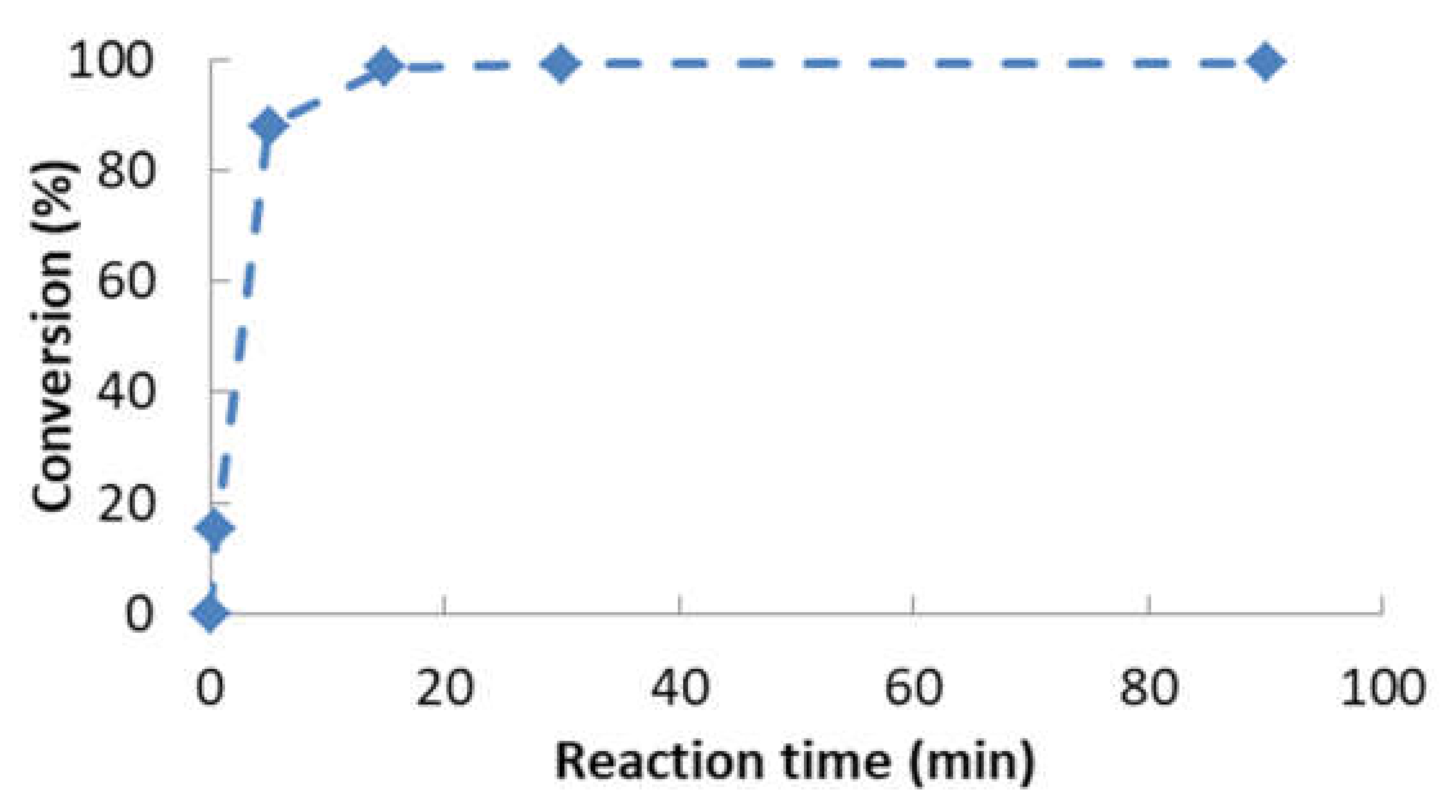
  • The optimum chemical conditions to obtain high yields of rapeseed biolubricant were biodiesel/alcohol (2-ethyl-2-hydroxymethyl-1,3-propanediol) mole ratio: 1/1; catalyst (sodium methoxide) concentration, 1.5% w/w; reaction temperature, 120 °C; reaction time: 90 min. Under these circumstances, high yields (exceeding 99%) were obtained.
  • The characteristics of the biolubricant were calculated, being equivalent to a SAE 10W30 lubricant, suitable for Diesel engines.
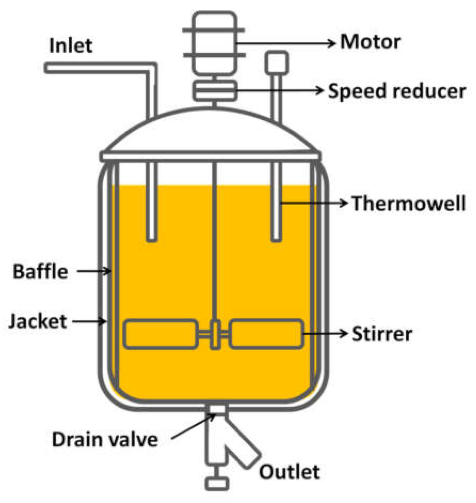
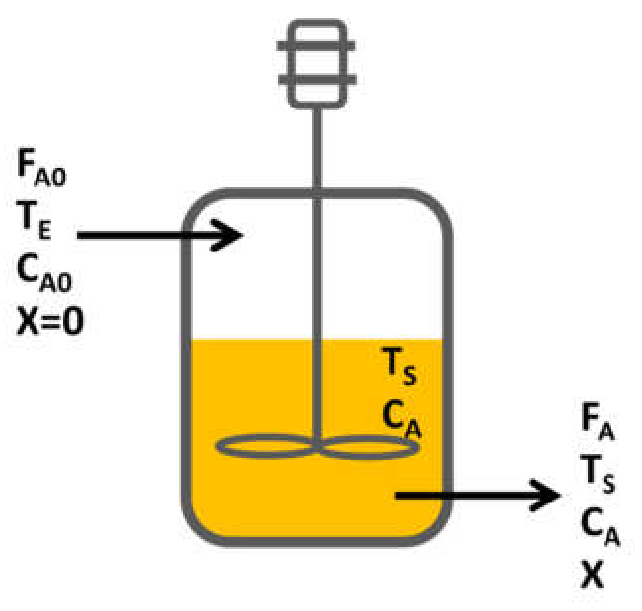
  • For the reactor design, due to the operating conditions, the kind of reaction and desired production, a continuous reactor was selected.
  • The kinetics of the process could be considered a pseudo-first order reaction, obtaining an activation energy of 6.91 kJ·mol−1.
  • According to the annual production (once the kinetics was known), a reactor volume of 9.66 m3 was obtained (12 m3 if oversizing is considered).

Author Contributions

Conceptualization, J.M.E. and S.N.-D.; methodology, J.M.E. and S.N.-D.; validation, J.M.E. and S.N.-D.; formal analysis, S.N.-D. and A.P.; investigation, S.N.-D. and A.P.; resources, J.M.E.; data curation, J.M.E., S.N.-D. and A.P.; writing—original draft preparation, S.N.-D. and A.P.; writing—review and editing, J.M.E. and S.N.-D.; visualization, J.M.E.; supervision, J.M.E. and S.N.-D.; project administration, J.M.E.; funding acquisition, J.M.E. All authors have read and agreed to the published version of the manuscript.

Funding

This research was funded by the “Junta de Extremadura” and “FEDER” (IB18028 and GR18150).

Institutional Review Board Statement

Not applicable.

Informed Consent Statement

Not applicable.

Acknowledgments

The authors would like to thank the “Junta de Extremadura” and “FEDER” for the financial support received to perform this study.

Conflicts of Interest

The authors declare no conflict of interest.

Nomenclature

CAoInlet concentration
CAOutlet concentration
FAoInlet mole flow
FAOutlet mole flow
k*Pseudo-first reaction order constant
−rAReaction rate
TEInlet temperature
TsOutlet temperature
VRReactor volume
XAConversion

References

  1. Salimon, J.; Salih, N.; Yousif, E. Industrial development and applications of plant oils and their biobased oleochemicals. Arab. J. Chem. 2012, 5, 135–145. [Google Scholar] [CrossRef] [Green Version]
  2. Encinar, J.M.; Nogales-Delgado, S.; Sánchez, N.; González, J.F. Biolubricants from rapeseed and castor oil transesterification by using titanium isopropoxide as a catalyst: Production and characterization. Catalysts 2020, 10, 366. [Google Scholar] [CrossRef] [Green Version]
  3. Cecilia, J.A.; Plata, D.B.; Saboya, R.M.A.; de Luna, F.M.T.; Cavalcante, C.L.; Rodríguez-Castellón, E. An overview of the biolubricant production process: Challenges and future perspectives. Processes 2020, 8, 257. [Google Scholar] [CrossRef] [Green Version]
  4. Beyzi, E.; Gunes, A.; Buyukkilic Beyzi, S.; Konca, Y. Changes in fatty acid and mineral composition of rapeseed (Brassica napus ssp. oleifera L.) oil with seed sizes. Ind. Crop. Prod. 2019, 129, 10–14. [Google Scholar] [CrossRef]
  5. Chozhavendhan, S.; Vijay Pradhap Singh, M.; Fransila, B.; Praveen Kumar, R.; Karthiga Devi, G. A review on influencing parameters of biodiesel production and purification processes. Curr. Res. Green Sustain. Chem. 2020, 1–2, 1–6. [Google Scholar] [CrossRef]
  6. Martínez, G.; Sánchez, N.; Encinar, J.M.; González, J.F. Fuel properties of biodiesel from vegetable oils and oil mixtures. Influence of methyl esters distribution. Biomass Bioenergy 2014, 63, 22–32. [Google Scholar] [CrossRef]
  7. McNutt, J.; He, Q.S. Development of biolubricants from vegetable oils via chemical modification. J. Ind. Eng. Chem. 2016, 36, 1–12. [Google Scholar] [CrossRef]
  8. Moncada, B.J.; Aristizábal, M.V.; Cardona, A.C.A. Design strategies for sustainable biorefineries. Biochem. Eng. J. 2016, 116, 122–134. [Google Scholar] [CrossRef]
  9. Checa, M.; Nogales-Delgado, S.; Montes, V.; Encinar, J.M. Recent advances in glycerol catalytic valorization: A review. Catalysts 2020, 10, 1279. [Google Scholar] [CrossRef]
  10. Nogales-Delgado, S.; Sánchez, N.; Encinar, J.M. Valorization of Cynara Cardunculus L. Oil as the Basis of a Biorefinery for Biodiesel and Biolubricant Production. Energies 2020, 13, 5085. [Google Scholar] [CrossRef]
  11. Nogales-Delgado, S.; Encinar, J.M.; Guiberteau, A.; Márquez, S. The Effect of Antioxidants on Corn and Sunflower Biodiesel Properties under Extreme Oxidation Conditions. J. Am. Oil Chem. Soc. 2019, 97, 201–212. [Google Scholar] [CrossRef]
  12. ISO. UNE-EN 14214:2013 V2+A1:2018 Liquid Petroleum Products—Fatty acid Methyl Esters (FAME) for Use in Diesel Engines and Heating Applications—Requirements and Test Methods; International Organization of Standardization: Geneva, Switzerland, 2018. [Google Scholar]
  13. ISO. UNE-EN-12634:1999 Productos Petrolíferos y Lubricantes. Determinación del Índice de Ácido. Método de Valoración Potenciométrica en un Medio no Acuoso; International Organization of Standardization: Geneva, Switzerland, 1999. [Google Scholar]
  14. ISO. UNE-EN 14111:2003 Fat and Oil Derivatives. Fatty Acid Methyl Esters (FAME); Determination of Iodine Value; International Organization of Standardization: Geneva, Switzerland, 2003. [Google Scholar]
  15. ISO. UNE-EN 116:2015 Diesel and Domestic Heating Fuels—Determination of Cold Filter Plugging Point—Stepwise Cooling Bath Method; International Organization of Standardization: Geneva, Switzerland, 2015. [Google Scholar]
  16. ISO. UNE-EN ISO 12966-2:2011 Animal and Vegetable Fats and Oils—Gas Chromatography of Fatty Acid Methyl Esters—Part 2: Preparation of Methyl Esters of Fatty Acids; International Organization of Standardization: Geneva, Switzerland, 2011. [Google Scholar]
  17. Focke, W.W.; Van Der Westhuizen, I.; Oosthuysen, X. Biodiesel oxidative stability from Rancimat data. Thermochim. Acta 2016, 633, 116–121. [Google Scholar] [CrossRef] [Green Version]
  18. Encinar, J.M.; Nogales, S.; González, J.F. Biodiesel and biolubricant production from different vegetable oils through transesterification. Eng. Rep. 2020, 1–10. [Google Scholar] [CrossRef]
  19. Varatharajan, K.; Pushparani, D.S. Screening of antioxidant additives for biodiesel fuels. Renew. Sustain. Energy Rev. 2018, 82, 2017–2028. [Google Scholar] [CrossRef]
  20. Dunn, R.O. Antioxidants for improving storage stability of biodiesel. Biofuels Bioprod. Biorefin. 2008. [Google Scholar] [CrossRef]
  21. Da Silva, J.A.C.; Soares, V.F.; Fernandez-Lafuente, R.; Habert, A.C.; Freire, D.M.G. Enzymatic production and characterization of potential biolubricants from castor bean biodiesel. J. Mol. Catal. B Enzym. 2015, 122, 323–329. [Google Scholar] [CrossRef]
  22. Encinar, J.M.; Nogales, S.; González, J.F. Biorefinery based on different vegetable oils: Characterization of biodiesel and biolubricants. In Proceedings of the 3rd International Conference in Engineering Applications (ICEA), Ponta Delgada, Portugal, 8–11 July 2019. [Google Scholar]
  23. Salimon, J.; Salih, N.; Yousif, E. Biolubricant basestocks from chemically modified ricinoleic acid. J. King Saud Univ. Sci. 2012, 24, 11–17. [Google Scholar] [CrossRef] [Green Version]
  24. Kania, D.; Yunus, R.; Omar, R.; Abdul Rashid, S.; Mohamad Jan, B. A review of biolubricants in drilling fluids: Recent research, performance, and applications. J. Pet. Sci. Eng. 2015, 135, 177–184. [Google Scholar] [CrossRef]
  25. ASELUBE Asociación Española de Lubricantes. Available online: http://aselube.net (accessed on 31 May 2020).
  26. Statista.com. Lubricant Sales in Spain. Available online: https://www-statista-com.ezproxy.unex.es (accessed on 31 May 2021).
Figure 1. Double transesterification for biolubricant production. R1 = alkyl group of fatty acids. R2 = alkyl group of the superior alcohol.
Processes 09 01224 g001
Figure 2. Effect of different FAME/alcohol ratios (1:1, 1:2; 1:1/2 and 1:1/3) on converScheme 100 °C; catalyst concentration, 1%; stirring rate, 500 rpm; reaction time, 90 min).
Processes 09 01224 g002
Figure 3. Effect of temperature. (FAME:alcohol ratio, 1:1; catalyst concentration, 1%; stirring rate, 500 rpm; reaction time, 90 min).
Processes 09 01224 g003
Figure 4. Effect of catalyst concentration (FAME:alcohol ratio, 1:1; reaction temperature, 100 °C; stirring rate, 500 rpm; reaction time, 90 min).
Processes 09 01224 g004
Figure 5. Conversion evolution during the second transesterification to obtain rapeseed biolubricant (FAME:alcohol ratio, 1:1; reaction temperature, 120 °C; catalyst concentration, 1.5%; stirring rate, 500 rpm; reaction time, 90 min).
Processes 09 01224 g005
Figure 6. Main components of a continuous reactor.
Processes 09 01224 g006
Figure 7. Scheme of a continuous reactor.
Processes 09 01224 g007
Figure 8. Linear representation of Equation (12) for the following chemical conditions: FAME/alcohol mole ratio, 1:1; catalyst concentration, 1.5% w/w; temperature, 100 °C; reaction time, 90 min; stirring rate, 500 rpm.
Processes 09 01224 g008
Figure 9. Dependence of k* with catalyst concentration (pseudo-first reaction order).
Processes 09 01224 g009
Figure 10. Theoretical and experimental conversions for the final experiment (FAME/alcohol mole ratio, 1/1; catalyst concentration, 1.5%; reaction temperature, 120 °C; reaction time, 90 min; stirring rate, 500 rpm).
Processes 09 01224 g010
Table 1. Transesterification conditions for biolubricant production.
ReactionReaction Time, minReaction Temperature, °CAlcohol/Oil Ratio 1Catalyst Concentration 2, %
First transesterification150606:11.5
Second transesterification901201:11.5
1 The alcohol used for the first transesterification was methanol, whereas for the second transesterification 2-ethyl-2-hydroxymethyl-1,3-propanediol was used. 2 The catalyst used in both cases was sodium methylate.
Table 2. Main features of rapeseed biodiesel and comparison with the standard (green tick = compliance; wrong red cross = non-compliance).
PropertyUnitsRapeseed
Biodiesel
EN-14214 LimitCompliance
with the
Standard
LowerUpper
FAME content%98.496.5- Processes 09 01224 i001
Moisturemg/kg250-500 Processes 09 01224 i001
Density at 15 °Ckg/m3868860900 Processes 09 01224 i001
Viscosity at 40 °Cmm2/s4.903.505.00 Processes 09 01224 i001
Flash point°C194101- Processes 09 01224 i001
Oxidative stabilityh5.378- Processes 09 01224 i002
Acid numbermg KOH/g0.35-0.50 Processes 09 01224 i001
Iodine numberg I2/100g105-120 Processes 09 01224 i001
Methyl linolenate% (m/m)9.1-12 Processes 09 01224 i001
CFPP°C−4−100 Processes 09 01224 i001
Table 3. Main features of rapeseed biolubricant.
Feature 1UnitsRapeseed BiolubricantCommercial
Lubricant 1
(SAE 10W30)
Commercial
Lubricant 2
(SAE 10W30)
Conversion%99.41n.d. 2n.d.
Density at 15 °Ckg/m3949859869
Moisture%0.03n.d.n.d.
Acid numbermg KOH/g0.28n.d.n.d.
Viscosity at 40 °Cmm2/s75.56669.8
Viscosity at 100 °Cmm2/s10.710.410.5
Viscosity indexDimensionless128145137
Flash point°C210232228
Combustion point°C222n.d.n.d.
Oxidative stabilityh4.94n.d.n.d.
1 All these determinations were carried out following the UNE-EN 14,214 standard. 2 n.d. = not determined.
Table 4. Average molecular weight of rapeseed biodiesel.
Methyl EsterPercentage (%)Molecular Weight (g/mol)Weighted Molecular Weight (g/mol)
Oleate66.4296.49196.87
Linoleate16.6294.4848.88
Linolenate9.10292.5026.62
Palmitate3.80270.4610.28
Stearate0.55298.501.64
Total96.45-284.29
Table 5. Flows at the inlet of the reactor.
ReactivesMass Flow(tm/Year)Volumetric Flow (m3/Year)Mole Flow
(kmol/Year)
Biodiesel5293.126098.0718,618.75
Alcohol2498.262313.2118,618.75
Catalyst116.87120.492163.07
Total7908.268531.7639,400.56
Table 6. Adjustment of data depending on catalyst concentration. Pseudo-first reaction order.
Units1%1.5%2%
k*,min−10.12130.13150.2512
R20.98690.99460.9242
Table 7. Adjustment data for different reaction temperatures. Pseudo-first reaction order.
Units100 °C110 °C120 °C
k*,min−10.12130.12690.1359
R20.98690.99840.8819
Table 8. Arrhenius equation. Adjustment data at 100, 110 and 120 °C by using Equation (15).
Slope (−E/R)InterceptActivation EnergyR2
−831.70.11516.91 kJ/mol0.9821
Table 9. Reactor volume determination.
VariableVariable Calculation, Units
Inlet mole flow, FAoFAo = 18,618.75 kmol·year−1= 0.5904 mol·s−1
Conversion, XAXA = 0.9941 (obtained from final experiment)
Inlet concentration, CAoCAo = FAo/FVtotal = 2182.3 mol/m3
Outlet concentration, CACA = CAo(1- XA) = 12.9 mol/m3
Pseudo-first reaction order constant, k*k* = 0.2827 min−1 = 4.7117.10−3·s−1
Reaction rate, −rA−rA = k* CA = 4.7117·10−3·12.9 = 6.078·10−2 mol/m3.s
Reactor volume, VRVR= FAo·XA/−rA = 0.5904·0.9941/6.078·10−2 = 9.6564 m3
Publisher’s Note: MDPI stays neutral with regard to jurisdictional claims in published maps and institutional affiliations.

