Article

Improvements of Micro-CHP SOFC System Operation by Efficient Dynamic Simulation Methods

Fraunhofer IKTS, Fraunhofer Institute for Ceramic Technologies and Systems, 01277 Dresden, Germany
*
Authors to whom correspondence should be addressed.
Processes 2021, 9(7), 1113; https://doi.org/10.3390/pr9071113
Submission received: 1 June 2021 / Revised: 16 June 2021 / Accepted: 18 June 2021 / Published: 26 June 2021
(This article belongs to the Special Issue Hydrogen Energy Systems: Optimization Models, Control and Simulation)

Abstract

:
Solid Oxide Fuel Cell (SOFC) technology is of high interest for stationary decentralized generation of electricity and heat in combined heat and power systems (CHP) for the residential sector. Application scenarios for SOFC systems in an electricity-regulated mode play an important role, especially in places where an electrical grid connection is not available or rather unstable. The advantages of SOFC systems are the high fuel flexibility and the high efficiencies also under partial load operation compared to other decentralized power generation technologies. Due to the long, energy-consuming system heat-up and the limited partial load capability, SOFC systems do not reach the performance of conventional power generation technologies. Furthermore, stack thermal cycling is associated with power degradation and should be minimized. In this paper, the improvement of these drawbacks are investigated for hotbox-based SOFC systems in the 1 kWel-class for residential applications. Since experimental investigations of the high-temperature systems are limited, modeling tools are established, enabling the visualization of internal system characteristics and providing the opportunity to simulate system operation in critical regions. To achieve this, a methodology for dynamic SOFC system modeling in a process engineering manner is developed based on the modeling language Modelica. A suitable approach is particularly important for modeling and simulation of the strong thermal interaction between the hot system components within the hotbox. The parametrized and validated models are used for the investigation of different dynamic effects, such as the system heat-up and the operation in low partial load points. A second reduced thermal system model aims for annual simulations of the SOFC system together with a battery to investigate the number of thermal cycles and the advantage of a hot standby operation. As a result, it is found that an adequate control of the power input at the start-up device and the cathode air flow has a high improvement potential to increase the stack heating rate and accelerate the heat-up in an energy-saving way. The hotbox-internal thermal management is identified as a crucial issue to reach low partial load points. To avoid the risk of stack cooling, lower heat losses and/or additional heat sources are of importance. Furthermore, the robustness of the tail gas oxidizer is found to be crucial for a higher load flexibility during partial load and the end of life stack operation. The annual simulation results indicate that operating the battery hybrid system with a hot standby mode requires much lower battery capacity for a high grid independence and a complete avoidance of system shutdown and associated power degradation.

1. Introduction

Decentralized generation of electricity and heat is a key contribution to increase energy efficiency and conservation of natural resources in a cost-effective way. This approach can help to clear the route for a broad introduction of renewables. Especially in places where access to electricity grid infrastructure is limited, decentralized generation can improve network coverage and security of energy supply. For this purpose, using high temperature fuel cell technology is promising for CHP production due to the high exhaust temperatures. Applications in cold countries can make use of the waste heat for residential heating and domestic hot water. In other climes, where space heating is not required, the waste heat can also be used for refrigeration engines or discharged to the environment. It is well known that fuel cell systems have the ability to run on higher efficiencies due to less energy conversion steps compared to widespread engine-driven stationary power production plants that are limited to the Carnot efficiency [1]. The possibility to operate SOFC systems under partial load at high stack efficiencies is advantageous. Furthermore, there is a high flexibility in the choice of fuels and dimensioning of the systems, while maintenance is comparably low. However, drawbacks in current SOFC applications are slow thermal system dynamics, i.e., resulting in long start-up times of more than four hours. Degradation rates are improved currently, but system shutdowns should be minimized. Since the systems should not be switched off regularly, the load flexibility is even more limited at relatively high system prices. For that reason, the improvements of the thermal management of SOFC systems and the optimization of the operational strategy is a crucial topic. This becomes particularly true considering the interconnection with strongly fluctuating real-world consumer demands.
Intense research is going on in the field of SOFC systems to make this technology broadly available for different stationary, portable and automotive applications. Typically, these systems range from some 100 Wel to 100 kWel electrical power output. Leaving the automotive sector unconsidered, four major application fields can be defined, namely:
  • Stationary grid-connected CHP systems in regions where space heating/cooling or domestic hot water production is required, especially introduced in European, Asian (Japanese), United States markets (heat-regulated mode);
  • Stationary off-grid battery hybrid systems for power or combined heat and power generation in places without reliable access to electricity (electricity-regulated mode);
  • Stationary grid-connected systems for power supply in the higher kW-class for industries or other (electricity-regulated mode);
  • Mobile off-grid power generator for power supply and uninterrupted power supply (UPS).
While long-established SOFC systems are based on conventional fuels like natural gas, the use of alternative fuels such as hydrogen, biogas or ammonia are brought into focus. The integration or combination of SOFC systems with other technologies as for the agriculture sector is investigated [2,3], e.g., with biomass gasification [4,5]. Furthermore, ammonia is an interesting hydrogen carrier that can be used easily in SOFC systems [6]. The coupling of SOFC systems with gas turbines is a long-term investigated field, which may also be expanded with the Power to X technology, as shown in [7]. The coupling of SOFCs with other technologies is interesting in terms of CO2 emission avoidance and cross-sectoral power generation. SOFC together with polymer-electrolyte membrane (PEM) electrolysis and refrigerating machines for power, heating, cooling and hydrogen production is proposed in [8]. Running the SOFC in the reverse mode to generate gases like syngas or hydrogen (also referred to as Power to Gas) [9,10] or to generate further used products such as waxes or crude oil (also referred to as Power to X) is, therefore, becoming the focus of research.
Furthermore, Fraunhofer IKTS contributes to the SOFC research field for various applications. Stationary grid-connected CHP systems were developed within the framework of different cooperative projects applying either in-house chromium-based interconnects (CFY) or a third party stack technology. The in-house SOFC stacks with CFY and electrolyte supported cells based on Scandia-doped Zirconia are utilized in different applications [11,12], in the reverse mode as an electrolyzer [13,14] and for system development based on alternative fuels such as biogas [15]. In the European project LOTUS [16], a system design was verified for an anode-supported cell technology for intermediate operating temperatures of 650 °C. The mobile 100 Wel power generator Eneramic [17] was another major development activity at IKTS, which is also based on the CFY stack technology. The entire stack and system design was focused on increased reliability and efficiency with respect to size, weight, handling and general applicability for the mobile sector [18].
The coupling of an SOFC system with storage devices considering different scenarios is an ongoing field of interest. In countries without fully developed electricity grid infrastructures, the configuration and operation strategy of SOFC systems differs significantly from those used in grid-connected heat regulated modes, especially due to the utilization of an electricity storage device. The hybridization enables off-grid operation of the SOFC system. Seeking for reliable electricity supply by means of decentralized production makes the application of SOFC systems an interesting option, as stated in the literature for scenarios as in India [19,20]. Other application scenarios are the self-sufficient operation of single houses at places where grid connection is not available, such as remote areas or mountain huts. The power supply for off-grid infrastructure facilities, such as telecommunication, is another field of interest [21].
This paper investigates the system design and the thermal management in 1 kWel-class SOFC systems. The state-of-the-art design is a hotbox design, integrating all hot system components in one insulted box [22]. This leads to lower thermal losses and higher efficiencies, compared to individually insulated components. The limitation of highly integrated systems is the strong thermal coupling and interaction between the components during operation. The stack is connected to a high thermal mass (hotbox) compared to separated insulation of an individual stack, thus resulting in complex control mechanisms and even lower transients especially during heat-up. Therefore, a dynamic process model of a 1 kWel SOFC hotbox system is introduced to identify improvement potentials for faster heat-ups and lower partial load points. Low dimensional, concentrated parameter models are developed, parameterized and validated based on experimental data.
Analyzing and improving the thermal management within hotbox systems by means of dynamic system models is the aim of this investigation. Furthermore, operational strategies for hybrid SOFC systems in conjunction with a battery are investigated for the power supply of a single family home. Based on the detailed model, a simplified hotbox model is derived and annual simulations are carried out for a SOFC system coupled with electrical storage devices.

2. Literature Review

In the literature, numerous SOFC system models for CHP applications can be found [23,24]. Steady-state system models aim to investigate advantageous system configurations and stationary operating points. In contrast to this, dynamic models aim to characterize the system operation and are therefore of major importance for further SOFC system improvements. The dynamic models can be utilized to analyze the thermal transients [22,25,26,27], the load following behavior [28,29,30,31,32,33], and to develop controls [34]. The bigger part of published dynamic models is based on a physical approach in contrast to few statistical, non-physical models or black box models [35,36], which is the most recent approach for system modeling, c.f. Table 1. A vast amount of reliable test data and high computing capacities are necessary to generate verified results without gaining knowledge about the internal system behavior. Therefore, a physical approach was chosen in the presented paper. The comparison of the different dynamic system models reveals the different modeling tools, which either is a sequential modeling language (Matlab/Simulink) or an object-oriented modeling language, such as Modelica, in addition to rarely used simulating software (as TRYSIS or Aspen Plus), see Table 1.
While most of the dynamic system models investigate the different system states and transients, they are mostly based on theoretical investigations without strict coupling to real-life systems and validation of the models (c.f. the last column of Table 1). This may be a reason why the system models are rarely utilized for optimizations. In contrast to this, a validated system model is presented in this work, utilized for optimization analysis.
Investigations of the thermal coupling in hotbox systems are rarely addressed in the literature. While Chen [42] investigates only the interaction between some hotbox components, Gallo et al. [22] investigates a non-classical hotbox with circulating air instead of an insulation material. In the work of Leucht [46], the thermal coupling of hotbox components is investigated, stating that the sequential execution in Matlab requires a signal feedback and high computing efforts. Further results of the work are not published. In the presented work, the SOFC system model is utilized to analyze the thermal hotbox behavior of a real-life SOFC system in order to identify the optimization potential. The modeling language Modelica with its non-sequential execution provides the possibility of efficient model implementation with short simulation times.
Considering the interaction of the SOFC system with the electrical and thermal consumer loads, publications can be found addressing different research questions. Liso et al. [55] investigate the preferable dimensions of the heating system and the fuel cell system for a single-family home situated in different cities in Europe. Adam [56] models a SOFC system serving the heat demands of a family home in London, indicating that thermal storage is beneficial for SOFC operation in terms of CO2 emissions. However, there is no general understanding of how to operate and dimension a SOFC/battery hybrid system.
Furthermore, hybrid systems are primarily known from different self-sufficient, also renewable generation technologies, involving photovoltaic, wind energy or gas turbines. In the literature, investigations can be found for PV systems in conjunction with batteries [57]. Due to the favorable dynamic characteristics, analysis on hybrid battery PEM fuel cell systems are existent, either used as stationary power supply [58] or back-up power. Vasallo [59] presents an analysis concerning the sizing of hybrid battery PEM systems for back-up and emergency power supply, similar to the work of Zhan [60] with a focus on the architecture and control. Employing battery storage in connection with a fuel cell system for automotive applications is another well-established research area. Brett [61,62] presents studies of a SOFC system with a ZEBRA battery for automotive applications.
Even though there is a high need for flexibility enhancement, the use of battery storage in connection with a stationary SOFC systems is rarely investigated. Brunaccini et al. [21] proposes the thermal coupling of a SOFC system and a high-temperature battery, investigating only the thermal interaction of both systems. Baldi et al. [63] propose a combination of SOFC/PEM systems with hydrogen generation and battery storage to cover the power and heat demand flexibly for two different off-grid use cases. To address this shortcoming, a model of the SOFC hotbox-based system in conjunction with a residential electricity consumer and a battery is investigated in the second part of the work. The focus is laid upon the SOFC system thermal behavior and the implications of operational modes and battery dimensioning, based on annual simulations.

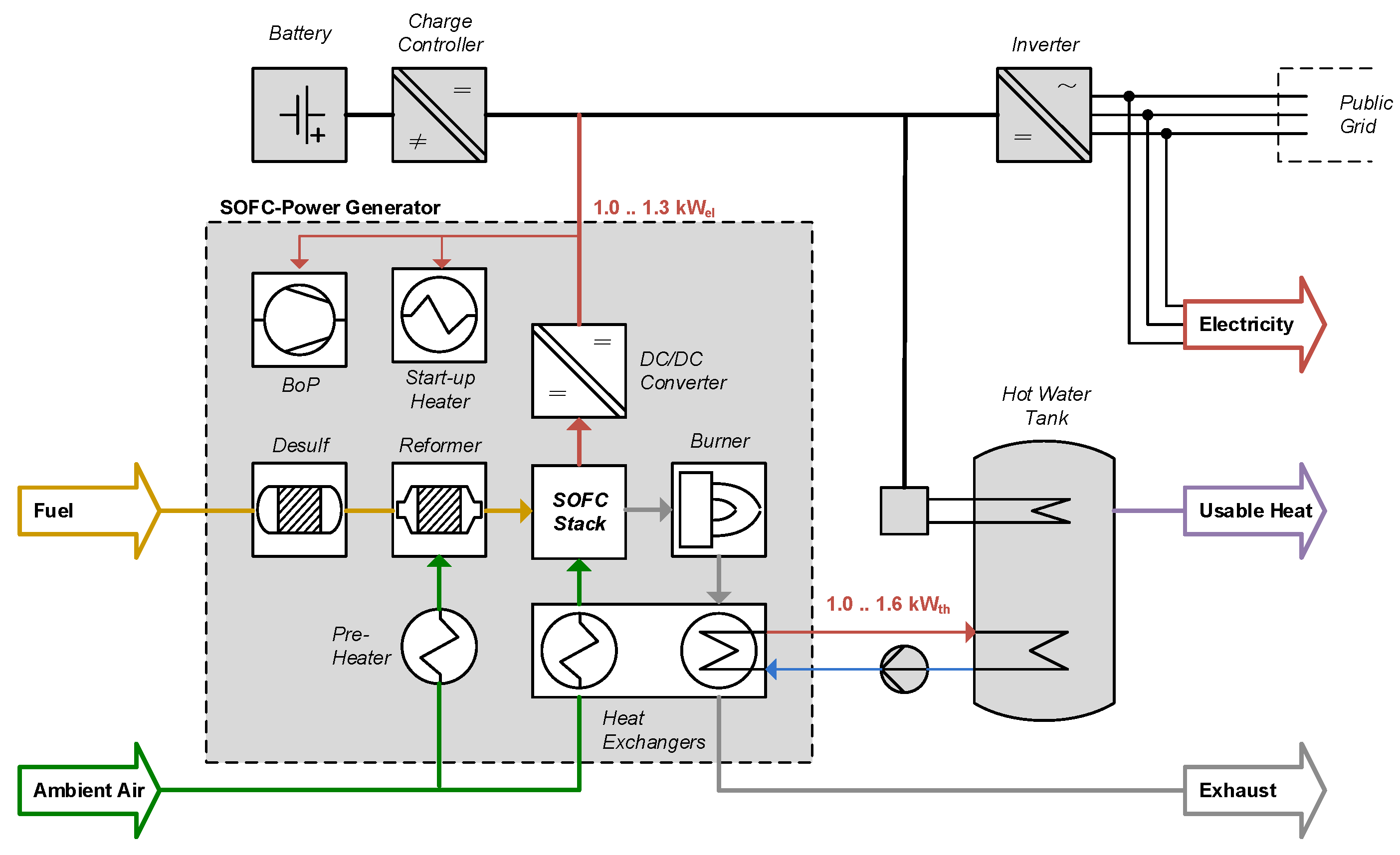
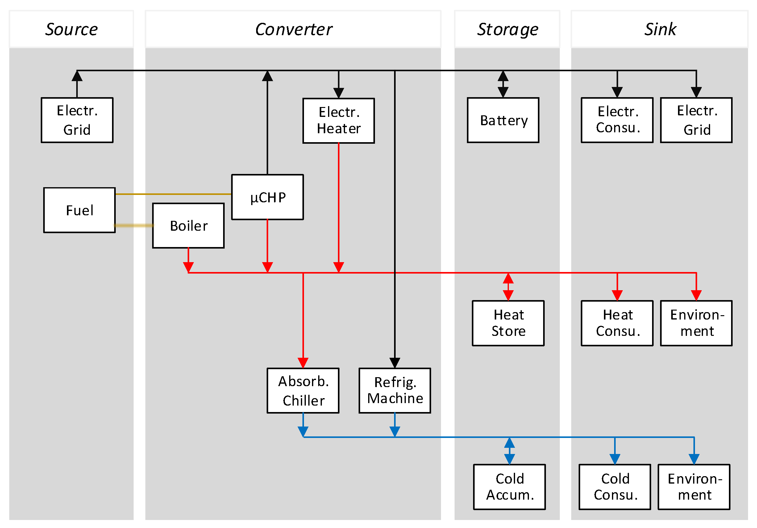
3. SOFC Hybrid System

The general application scenario of SOFC systems in the residential sector may differ based on the boundary conditions and scenarios. Generic models aim to visualize the potentials and interactions of different sources, converters, storage devices and sinks. The different system configurations are visualized in a generic model, see Figure 1. It can be seen that, in principle, chemical-bounded energy from the fuel is supplied to the system. Moreover, solar radiation can contribute to the electricity and heat supply via PV modules or solar collectors. Electricity may be another partial energy source for the system, as in a grid-connected system. The SOFC system is illustrated as an energy converter, supplying electricity and heat to the particular storage devices. Additionally, refrigeration units may serve as a converter to generate cooling energy. The consumer of electricity or heat and the environment functions as a sink for the system. In the case of the feed-in option, the electricity grid can also function as a sink.
It can be assumed that based on the generic flow chart, all relevant cases for stationary SOFC system applications can be derived. In particular, electricity-regulated SOFC systems can be deduced from the general model, as illustrated in Figure 2. The electricity from the battery and the SOFC system has to meet the end-user demand with partial use of the grid. The heat demands may be provided by the heat storage and the SOFC system. An electric heating rod based on natural gas aims to supply additional heat requirements.
For this scenario, a 1 kWel SOFC system based on natural gas is developed based on partial oxidation (POX) [64,65], which is the simplest way of reforming in terms of systems integration and complexity, even though electrical efficiencies are lower compared to steam reforming systems [16]. Figure 3 displays the arrangement of the SOFC hybrid system with its main parts. A battery with the charge controller, the inverter and the hot water tank with a heating rod are the peripheral devices. For the SOFC system, the state-of-the-art system integration with a hotbox is applied. All hot components of the system are integrated into one insulation box; namely, the start-up heater (electrical air pre-heater, EAPH), the POX reactor and the oxidant air pre-heater (OPH) prior the reformer, the stack and the burner (tail gas oxidizer, TOX). Lower heat losses to the surroundings can be achieved due to the lower heat transfer surface compared to systems with a separated insulation of each component. Moreover, heat management within the hotbox is possible by a dedicated arrangement of the components, enabling a balancing between hot components with heat supply (e.g., TOX) and components with heat demands (e.g., OPH).

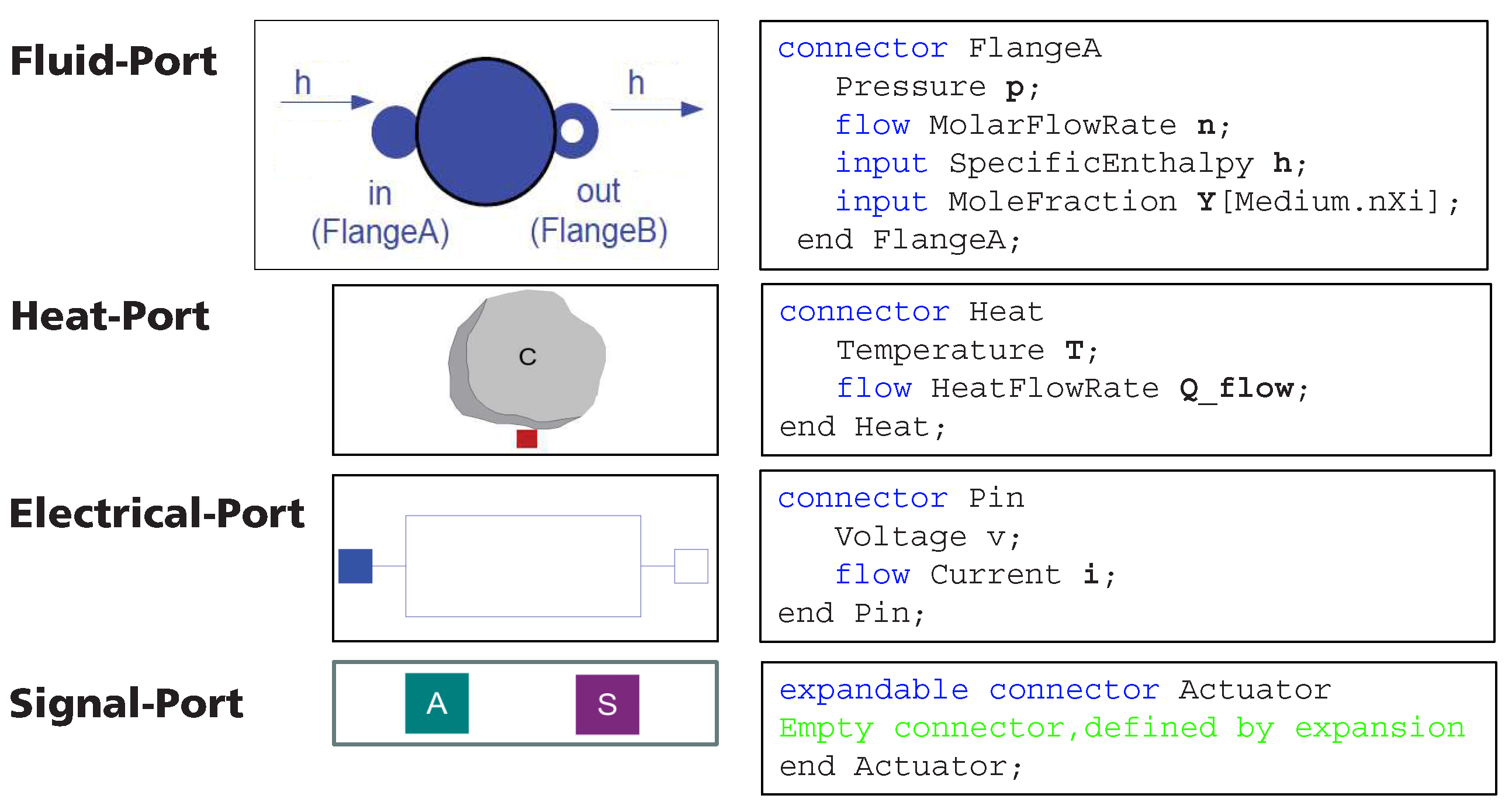
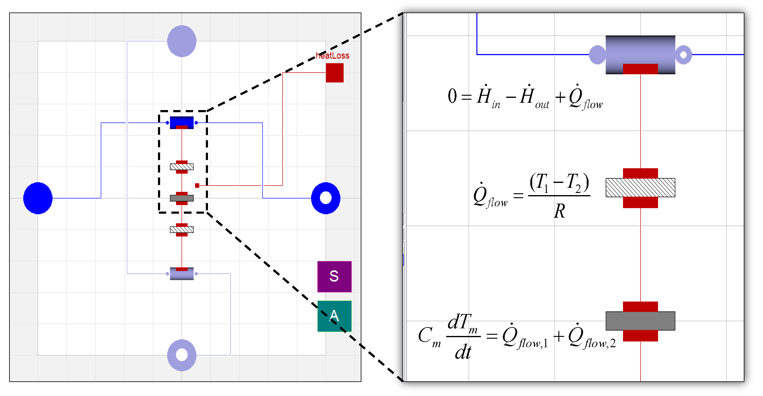
4. System Modeling Methods

Describing a thermal strongly coupled hotbox-based SOFC system dynamically is challenging, and a distinct modeling approach is not established yet. High dimensional 3D multi-physics models [66] have been inapplicable for the description of several interacting components in a system due to limited computing capacities until today. A reduced 3D model using symmetrical axes is shown in [67,68], also indicating that 3-D models for transient system simulations appear to be not manageable.
Therefore, low dimensional models, e.g., 0D models with a simplified description of the behavior for one point with concentrated (or lumped) parameters [69,70] can be applied for system modeling. These models are also referred to as network models or macro-level models. This approach is demonstrated for SOFC systems in the literature [71,72], accentuating the simplicity of the model development at short computing times and fair accuracy. Nonetheless, while basic functions of the systems can be described, peripheral phenomena and extraordinary process states cannot be evaluated. Furthermore, approaches of mixed dimensional models are found in the literature, claiming the potential to balance the disadvantages of each approach [73].
In this study, a low dimensional, physical, transient system model is developed for a hotbox-based 1 kWel-class SOFC system, c.f. Figure 3. For modeling the open-source physical modeling language, Modelica is used, taking advantage of a physical modeling approach with object-oriented modeling paradigms and the ability to work with inheritance. Most importantly, using potential and flow data for the connections between components (such as heat or volume flow) provides the opportunity for an intuitive physical modeling. Figure 4 gives a simple example of an electrical resistance implemented in the modeling approach of the object-oriented approach compared to non-reactive, sequential, signal flow-based approach (causal) as in Matlab/Simulink [74].
Within this work, a new Modelica modeling library is established based on the published “ThermoPower” library [75]. Therefore, the connector definitions for fluid, heat, electrical and signal ports are defined, see Figure 5.
An exemplary fluid element base class with two fluid ports and one heat port of the SOFC library is given in Figure 6.
In addition, the physical effects are modeled within basic elements such as for heat conduction and heat convection. Figure 7 gives an example of the connected base models for a heat exchanger component model. The arrangement of the base models and parameters of all components are based on the real-life system component design.
The in-house tool for the description of the stack behavior in a 0D model is integrated with the basic energy balancing as stated in Equation (1), considering the inlet and outlet flows, the heat of reaction, the electrical dissipating heat and the heat losses with:
C eff , Stack d T Stack d t = H ˙ in H ˙ out + Q ˙ reac + Q ˙ el , diss . + Q ˙ loss .
The model is parametrized with actual stack data by determining the stack internal resistance, see [16]. Furthermore, the reforming reaction is modeled based on the chemical equilibrium
a · A + b · B c · C + d · D
with K Reac = c ( C ) c · c ( D ) d c ( A ) a · c ( B ) b ,
which is a reliable assumption according to experimental works [76].
In Table 2, the assumption for each component in the system model is summarized by stating the energy balancing assumption, the chemical conversion and the heat transfer mechanisms. The balance of mass and momentum are stationary for each fluid component.
In the actual system, the hot components are compactly arranged within the hotbox, as shown in Figure 8.
To realize the hotbox arrangement in the model, the components are connected with thermal and fluidic interconnections, see Figure 9. Most importantly, a virtual heat capacity is introduced, representing the surroundings of the hotbox components. Each component of the hotbox is thermally coupled to this thermal mass, thus exchanging heat flow based on the temperature level of each component.
The heat transfer can also be modeled as a resistance, assuming the heat flow as a flow variable and the temperature as the potential variable, c.f. [77]. The following equations give the theoretical background [78] by:
Q ˙ j = T i , j T a , j R j
with R j = 1 α i A i + n = 1 N δ n s n A m + 1 α a A a .
Figure 10 shows the thermal resistance model of the hotbox with the necessary parameters to characterize the heat transfer effects between the components. These parameters are identified based on hotbox test results by means of the least-square method. Another set of test data is utilized to validate the model, as shown in the Results section.
With the detailed process model, simulation times are fair for parameter studies of the system with a simulation time of 0.5 h for a whole system test procedure of 100 h. In order to investigate the application scenario within annual simulations of the SOFC system together with the battery and a residential consumer, the detailed model needs to be reduced. Figure 11 gives a schematic representation of the reduced SOFC system model for the annual simulation, which is basically a heat source with a capacitive insulation.
The associated equations for the hotbox model are:
C Hotbox d T Hotbox d t = Q ˙ SOFC , i Q ˙ Loss , i ( t )
with Q ˙ Loss , i ( t ) = k A Insul , Hotbox · ( T Hotbox , i ( t ) T Ambient ) .
With this approach and the characteristic values from the detailed model, the hotbox temperature can be determined during the annual simulations.
For modeling the battery, a simple model from the published Modelica library “BuildingSystems” is used [79]. For the residential user, a load profile based on standardized type day definitions according to the VDI 4655 is used for a German climatic region [80], see Figure 12. With these components, a simple hybrid system can be modeled in an electricity-regulated mode with a 60-s step size, neglecting the thermal side in the first step; see the Results sections.

5. Results

The simulation results for a whole test cycle of the SOFC system model are shown in the form of temperature curves over time measured at different places within the hotbox in Figure 13 and Figure 14. The POX air inlet temperature during heat-up cannot be modeled since there is no oxidant air added at this stage. The temperature rise is only due to the hotbox heat-up and the heating of still air at this point. During switching and the sudden start of the reforming and the combustion reaction, an overshooting at the switching points is visible.
The temperatures can be modeled with a low deviation of less than 4% for all load points, except for the TOX temperature, which shows a deviation up to 6% during higher load points. Interestingly, the deviation at the POX inlet from the OPH is higher for lower partial load points, thus revealing the different temperature levels and a mismatch between the measurements and the simulation within the hotbox during different load points. This fact will be discussed later on.
Different investigations are possible by means of the validated dynamic SOFC system model, thus providing access to system and hotbox internal data that enable a knowledge gain, as shown in the following sections.

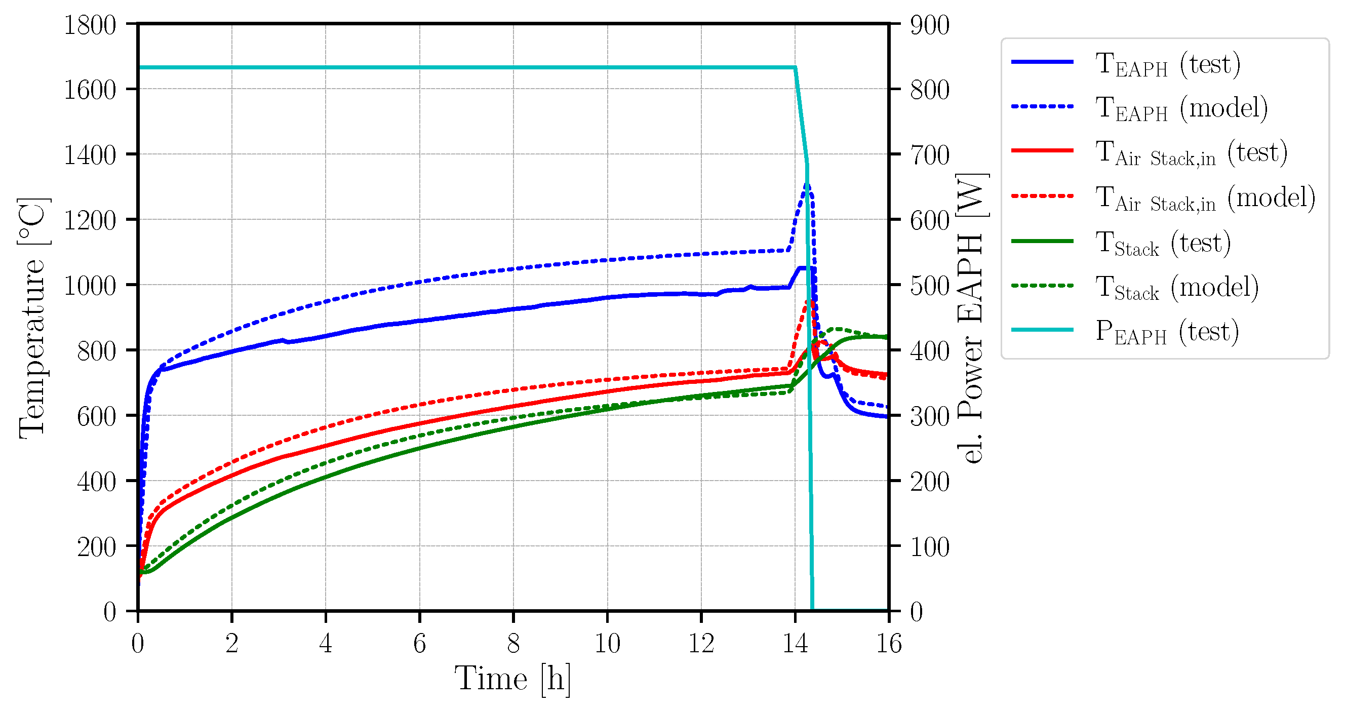
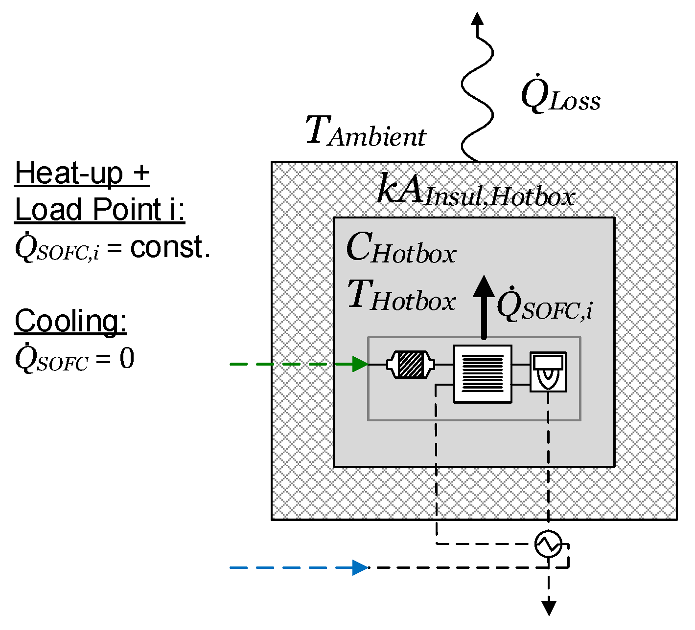
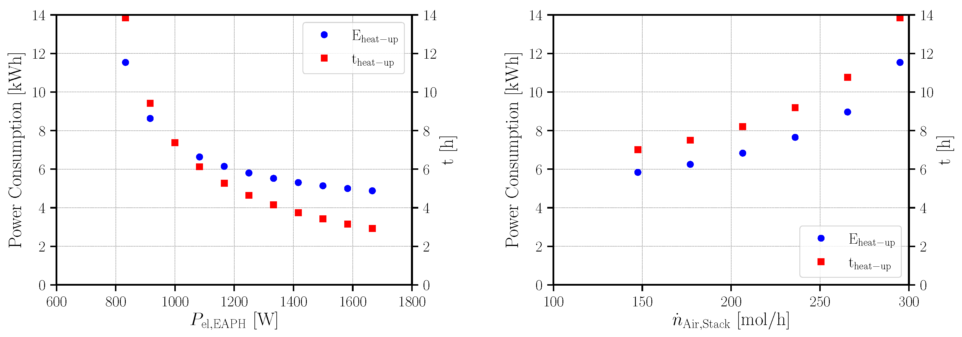
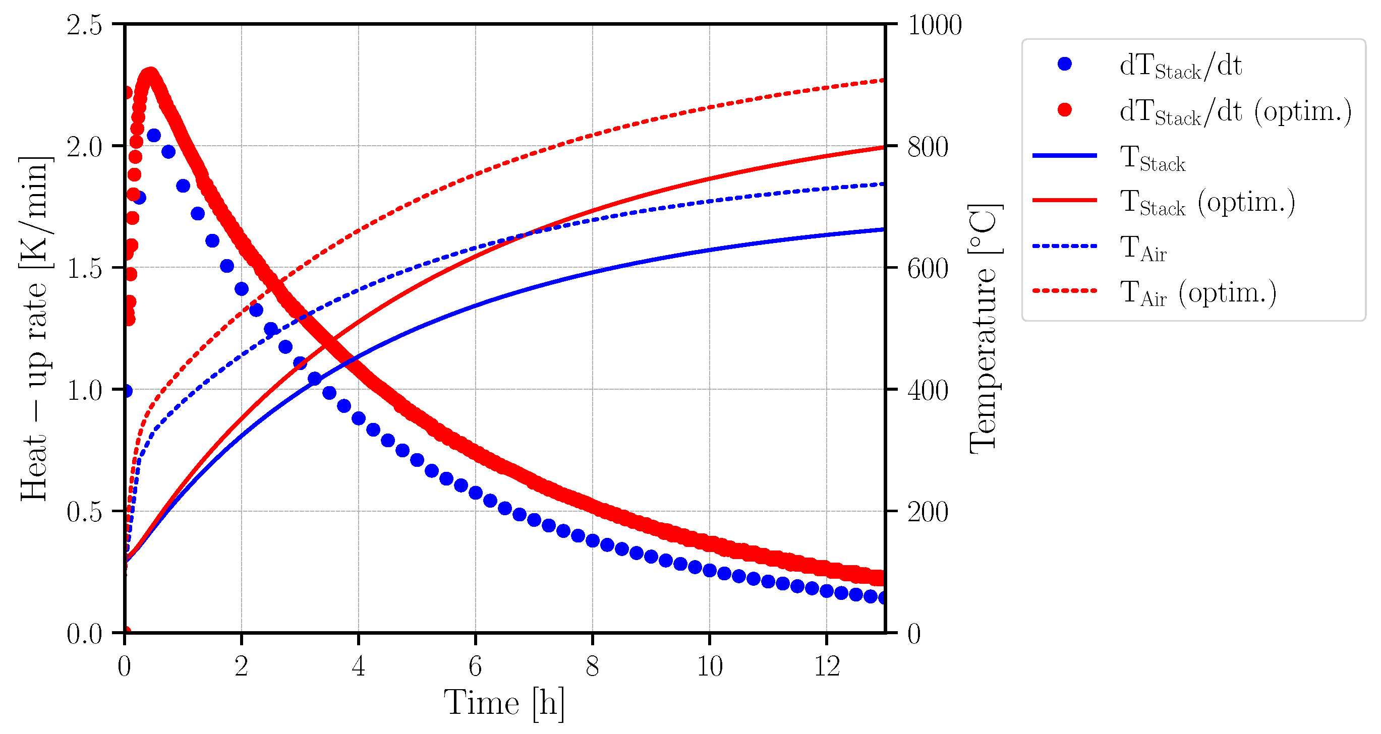
5.1. Improvement of the System Heat-Up

The heat-up time of the 1 kWel SOFC system with an electric air pre-heater prior to the stack and the relevant temperatures can be seen in Figure 15. Due to the relatively low electrical power input, the heat-up time sums up to 14 h, which is comparably high to systems with 6 h heat-up times on the same scale. For this special system development, a fast heat-up was not required due to the continuous operation. However, a more flexible and more efficient system operation can be achieved by a reduction of the heat-up time. This may be an important contribution to expanding the field of application of the SOFC system.
With the validated system model, parameter variations are used to identify the improvement potentials regarding heat-up times and resulting power consumptions. The target stack temperature is assumed to be 670 °C, thus only looking at the heat-up (OCV-mode of the stack) and excluding the heating effects by the stack current ramp-up. As a restriction, the maximum allowable temperature levels within the components are monitored and kept under the allowable levels as in the real-life system.
Most importantly, the electrical power input and the cathode air input are identified as values of high impact during heat-up. Figure 16 shows the effect of higher power inputs at the EAPH at the left and the effect of lower cathode air input at the right. Considering the temperature limits in the actual system design, the power input can only be increased up to 115% (1015 W) and the air can only be reduced by 20% (235 mol/h). Additionally, the maximum allowable temperature gradient between the cathode air inlet temperature and the stack temperature needs to be considered to avoid stack damaging.
Interestingly, the higher power input leads to lower overall power consumption at shorter heat-up times. Reducing the cathode air input leads to the same effects. In order to achieve a faster, energy-saving heat-up, both effects can be combined. Under consideration of the maximum temperature levels in the actual system design, the variables may be set as follows:
  • Increase of electrical power input to the EAPH by 10% (883 W to 916 W) and
  • Reduction of cathode air input by 20% (295 mol/h to 236 mol/h),
thus resulting in a heat-up time reduction of 48% to 7.42 h at a power consumption reduction of 40% of 4.55 kWh. The resulting stack heat-up rates, air inlet and stack temperature for the base case and the improved heat-up are displayed in Figure 17. With the optimized mode, a higher stack heat-up rate can be achieved, resulting in a faster stack heat-up than for the base case.

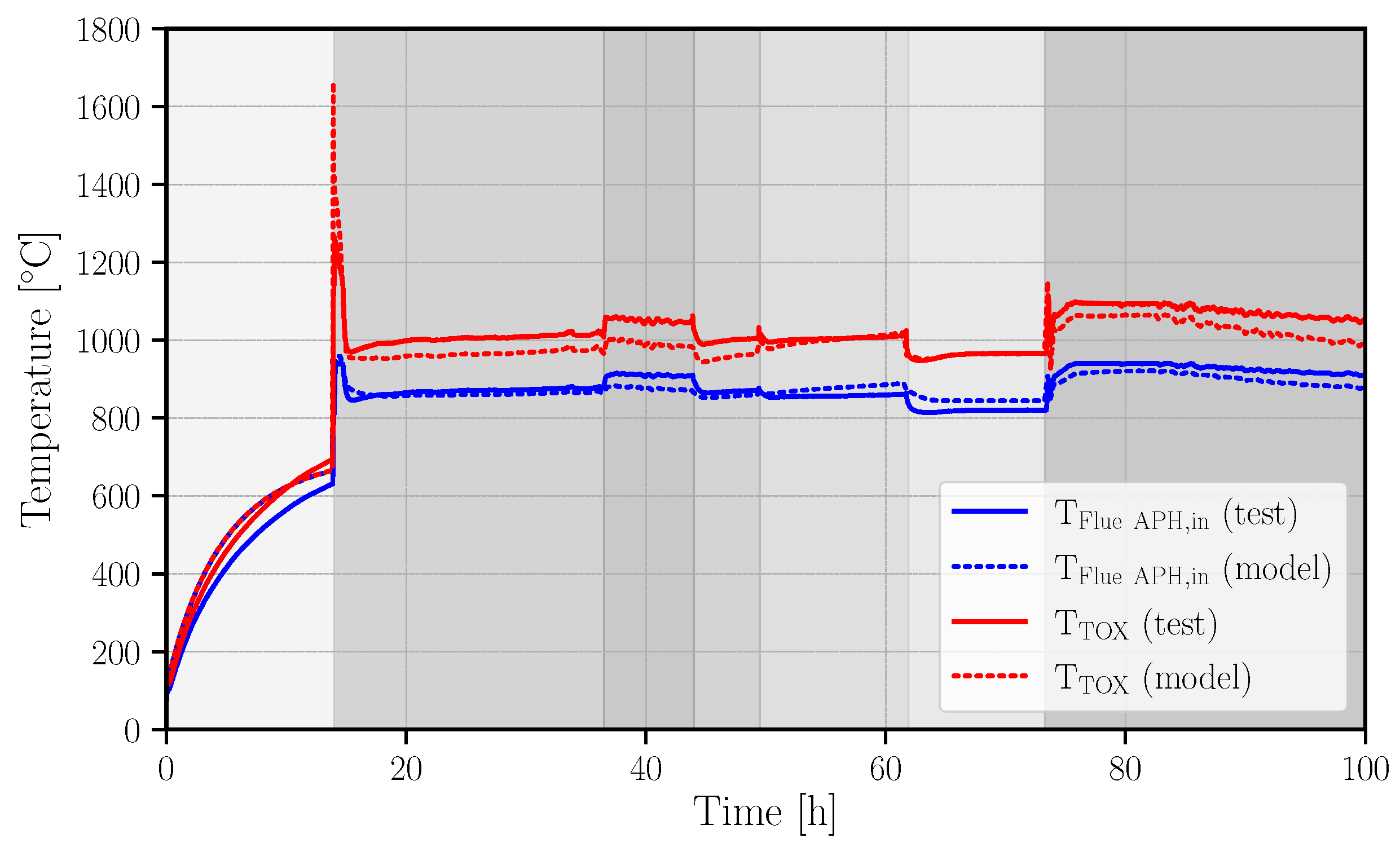
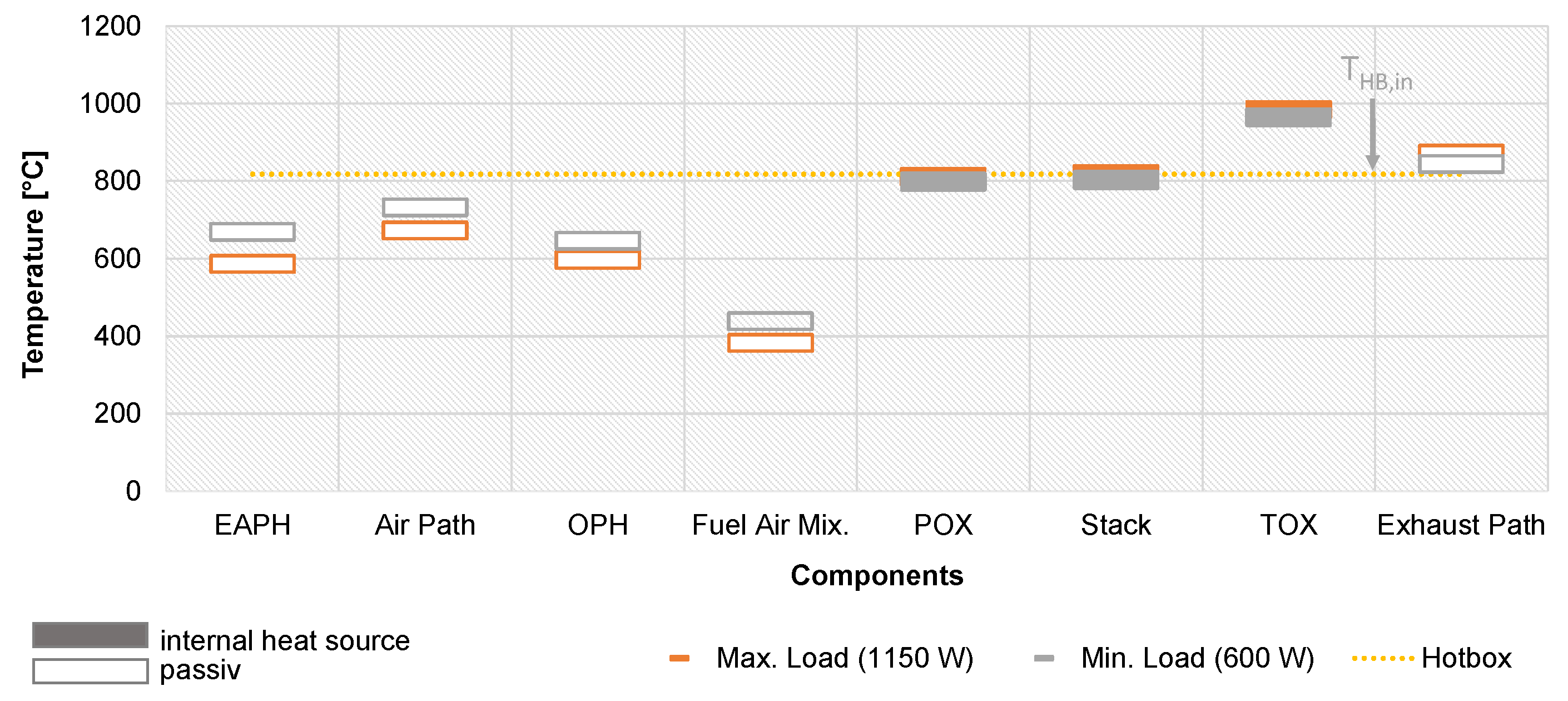
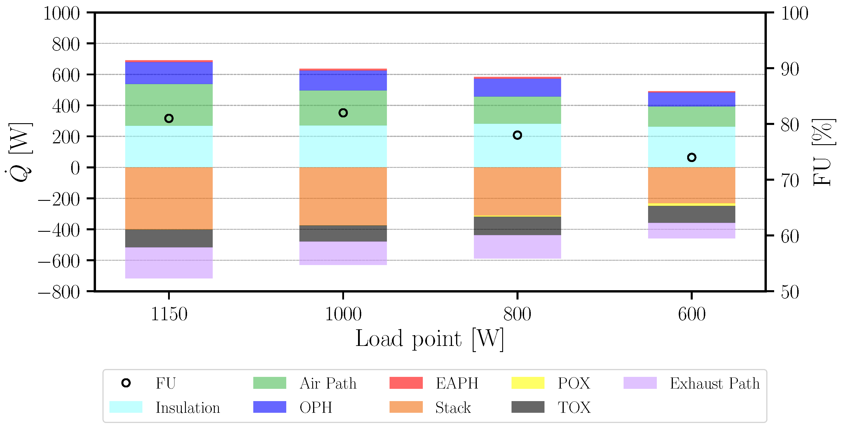
5.2. Partial Load Behavior

In the temperature curves of the hotbox components (c.f. Figure 13 and Figure 14), it is clearly visible that the component temperatures vary at each operational point. This is also indicated by the package voltage measurements at the stack during load changing, revealing lower voltages in the upper part of the stack due to lower temperatures. At low operational points, the upper part of the stack cools down, while the TOX under the stack heats the stack from the bottom, c.f. Figure 8. Figure 18 shows the different temperature levels for the maximum and minimum load points. Furthermore, the temperature of the hotbox, modeled as the virtual heat capacity, is displayed. Components that are at a higher temperature level than the virtual capacity heat the hotbox, while colder components draw that heat from the hotbox. Most importantly, the TOX serves as an active internal heat source due to the combustion reaction inside, thus leading to the major heat input during all load points.
During operation at lower partial load points, it is crucial to keep the stack temperature at a constant level. To avoid a stack cooling for operating the minimum load point of 600 Wel, it was necessary to decrease the fuel utilization of the stack to 74% compared to around 80% at the higher load points. This leads to a higher conversion of the combustibles in the TOX. This effect can be seen in the amounts of transferred heat from the components to the hotbox and can be visualized with the simulated values for each load point, see Figure 19. The bars indicate the amounts of heat that are either released from the components to the hotbox (negative values) or absorbed from the components (positive values). While the released heat from the stack reaction and the exhaust path is decreased towards low operating points (orange and purple bar), the heat losses via the insulation remain at a constant value due to the nearly constant stack and hotbox temperature. The TOX equalizes the heat balance at 600 Wel as a result of the reduction of the fuel utilization within the stack.
Due to the limitation of the maximum temperature level in the TOX, it was not possible to decrease the fuel utilization of the stack further during testing of the actual SOFC system. Therefore, system operation at load points lower than 600 Wel could not be carried out. At the low load points, the stack temperature could not be maintained at constant levels. The amounts of transferred heat within the hotbox provide the explanation. Running the system at hot standby operational point without transferring net electrical power could not be realized with the present system.
For the sake of the load flexibility of SOFC systems and their efficient utilization for electricity and heat generation (also compared to conventional generators), stable operation at low partial load points would be favorable. Therefore, different possibilities appear to enable a system operation at lower partial load points:
  • Improvement of the arrangement of the hotbox components to:
    Enable a better heat transfer from the hot to the cold hotbox components,
    Achieve a smaller size of the hotbox for heat loss reduction.
  • Improvement the of hotbox materials with:
    Higher heat transfer between components,
    Lower heat capacity to reduce the thermal inertia of the system,
    Improved insulation with less heat loss, e.g., using evacuated cabinets.
  • Improvement of the TOX by:
    Application of high-temperature stable materials to realize higher combustion temperature and further stack FU reduction,
    Redesign the TOX to homogenize and reduce the combustion temperatures, e.g., with a porous burner or adding of cooling air.
  • Deploying another heat source within the hotbox by:
    Using the POX reformer device as an additional heater (considering temperature limits and reformate qualities),
    Using the EAPH (or alternatively a separate start-up burner),
    Introducing an additional electric heater, e.g., at the stack insulation (c.f. [25,81]).
  • Considering a slightly lower stack and hotbox temperature during lower load points

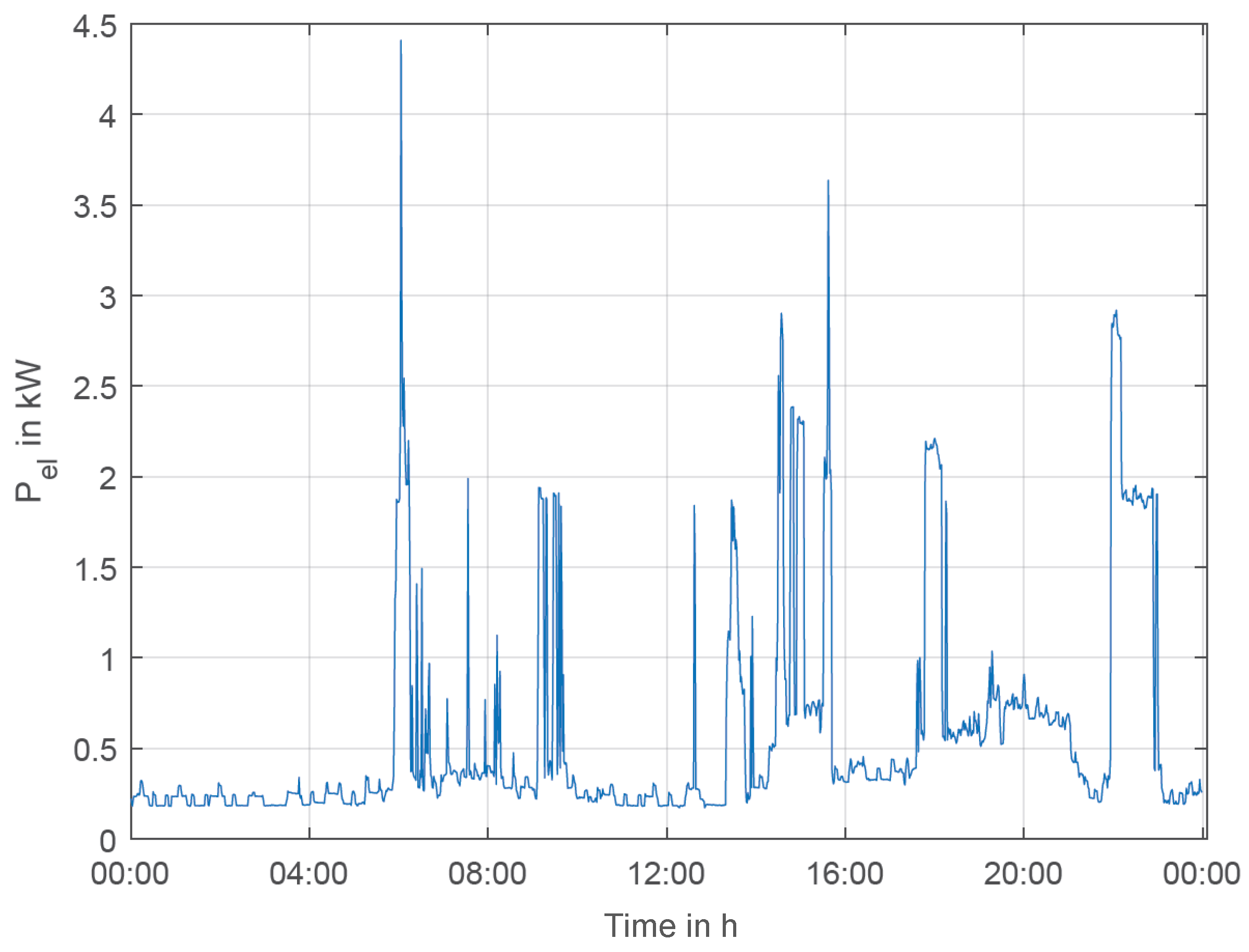
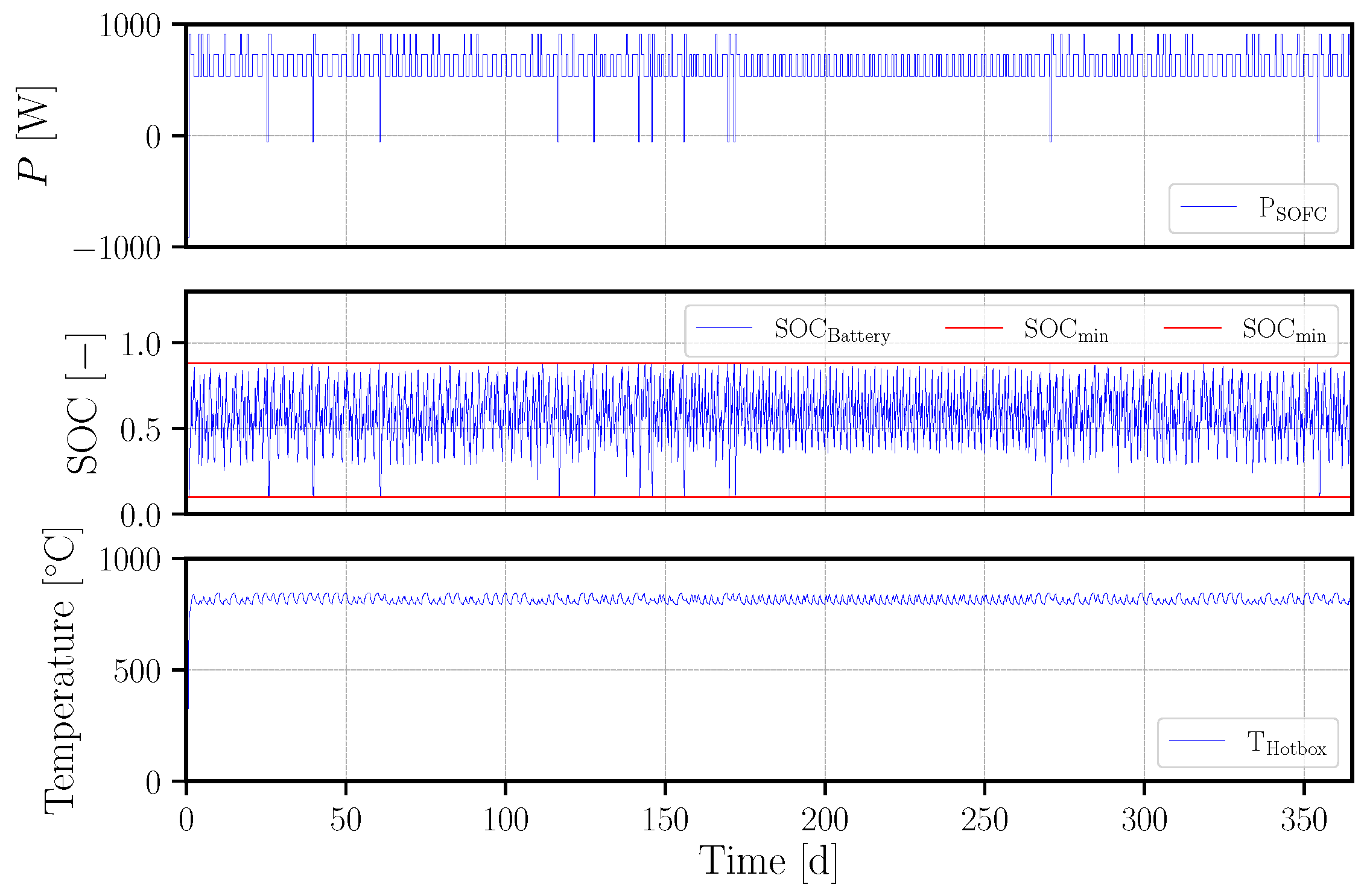
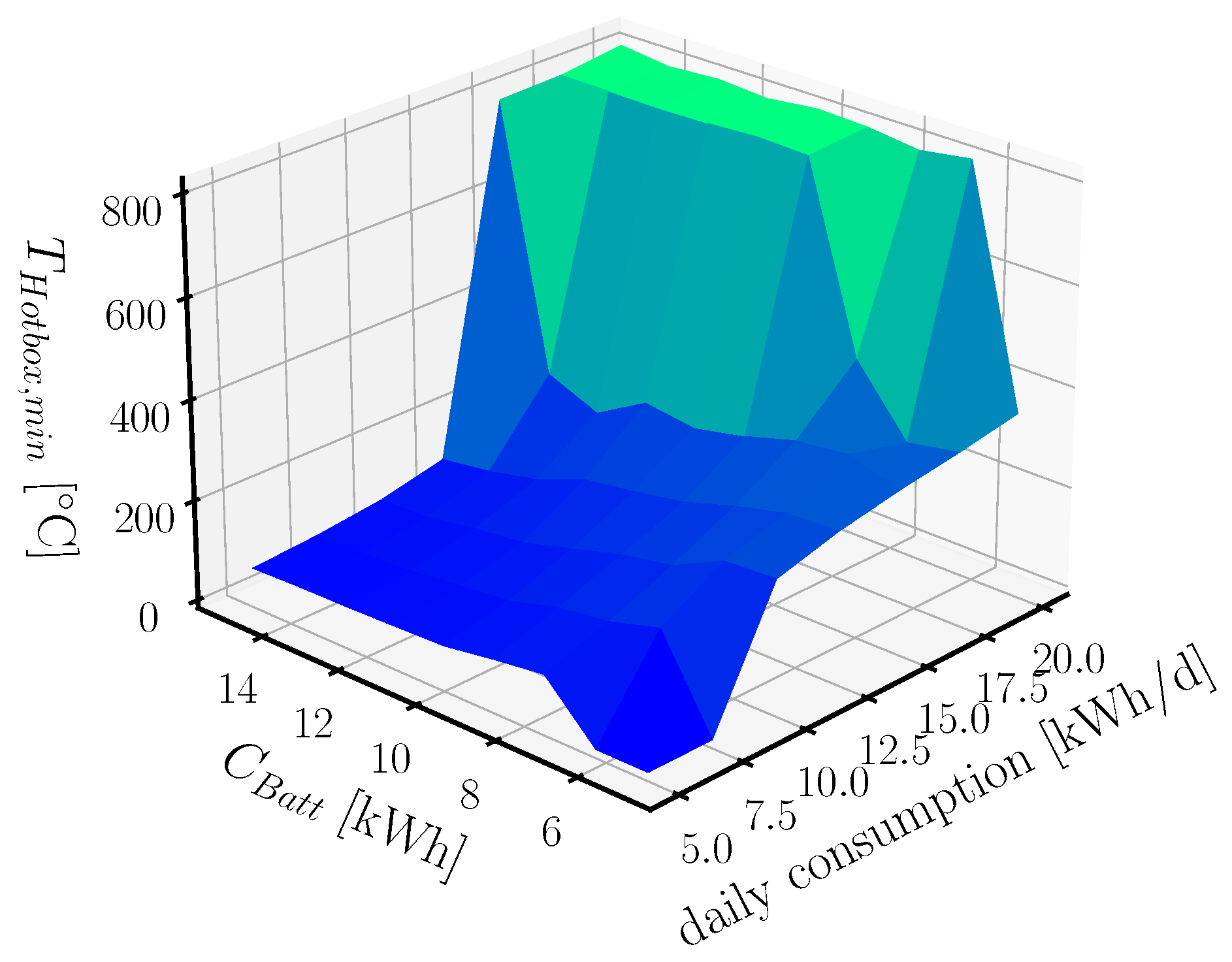
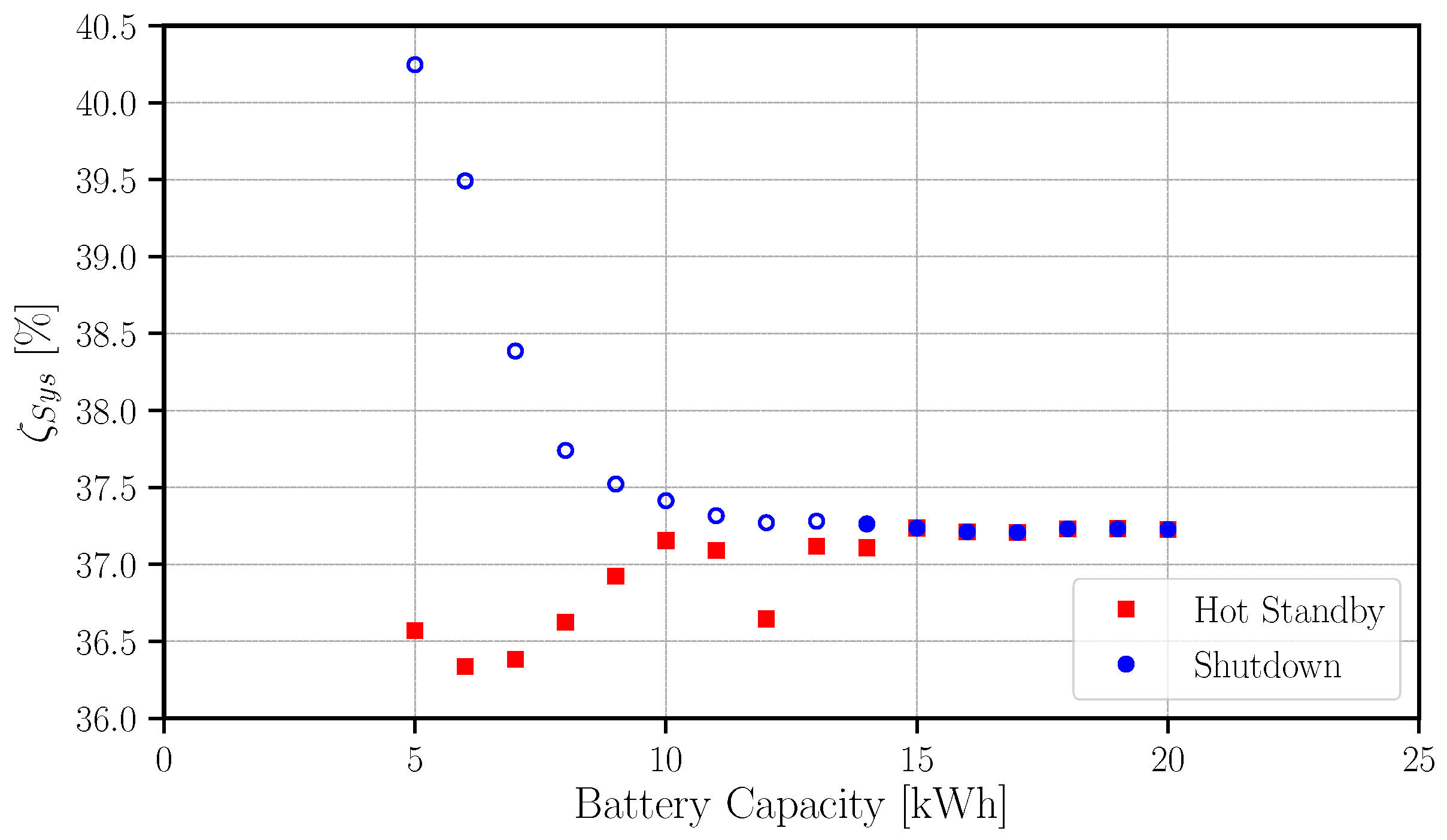
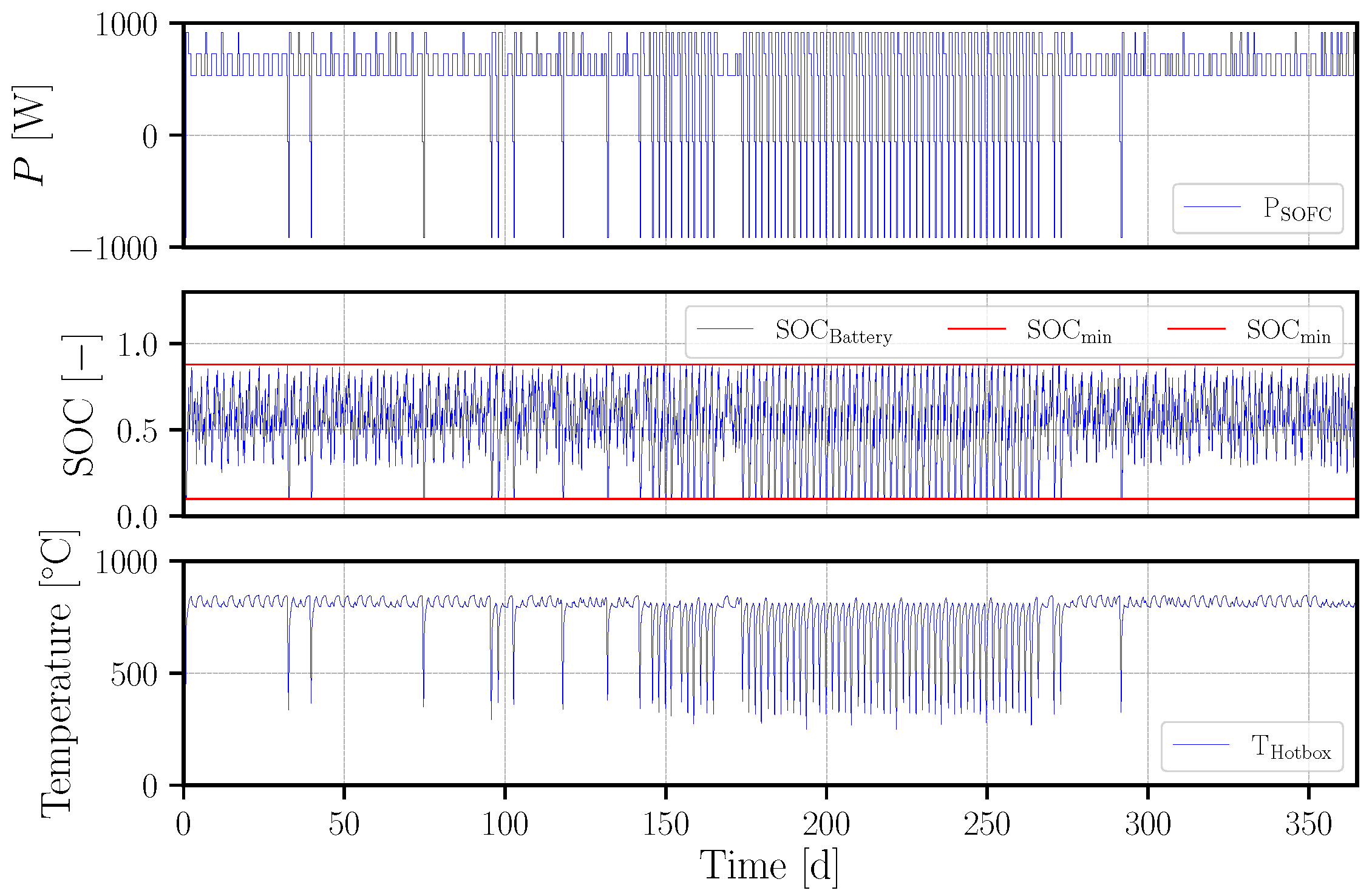
5.3. Simulation of the Hybrid System in a Residential Application Scenario

To improve the load flexibility of SOFC systems, the hot standby operation is discussed in the literature [82]. During this operation, the system is kept at a high-temperature and the generated electricity is used internally, while the net power output of the system is zero. As a result, system cooling and the thermal cycling of the stack with irreversible power degradation is avoided. Nowadays, SOFC stacks are limited to a maximum number of thermal cycles of around 60 throughout their lifetime, including maintenance and emergency cutout of the systems. While improvement of stack durability is an ongoing field of research, using a complete shutdown of the system to improve the load flexibility is not recommended. The positive effect of the hot standby operation regarding system durability by thermal cycle avoidance is non-controversial in the literature [83,84].
Annual simulations of the battery hybrid systems are conducted in a real case application scenario to investigate the effects of the hot standby operation compared to system shutdowns. A simulation step size of 60 s is chosen. The hybrid system consists of a connection to the electrical grid, the SOFC system with three different load points (full load, partial load 1 and partial load 2) as a converter, a battery as storage, the electrical consumer and the grid as the sink (c.f. Figure 2, only power side). Since the SOFC system is operated in a power regulated mode and an exhaust cutout is foreseen for the system, it may be used as a power generator only, thus neglecting the thermal demands.
The exemplary annual simulation for a system with shutdown is shown in Figure 20 in comparison to a system with hot standby operation, see Figure 21.
In this exemplary configuration, the SOFC systems need to be shut down more than 60 times during the year, especially during summer time. During the 5–6 h shutdown time, the hotbox cools down to 300 °C, thus representing a full thermal cycle. According to the literature [83,84], a cooling down of 200 K is considered as a thermal cycle with associated power degradation. The high hotbox heat capacity of the SOFC systems cannot avoid a thermal cycle in this case. For the hot standby operation of the same configuration, the hotbox is kept on high-temperature levels throughout the year.
The effect of the shutdown on the minimum hotbox temperature can be seen in Figure 22 for different daily electricity consumptions and battery capacities. It is visible that the thermal cycles can be avoided when high battery capacities or a high daily electricity consumption of the user is applied. In the case of the hot standby operational mode, the hotbox temperature is at a high level at each point of the parameter field.
Comparing the energetic performance of the systems reveals the effect of the surplus fuel input when running in the hot standby mode. The degree of efficiency considers the annual energies and is defined as:
ζ Sys = E el , SOFC E Fuel + E el , Grid .
The results for both operational modes are shown in Figure 23 for the daily electricity consumption of 15 kWh/d. This indicates clearly that SOFC systems in this specific configuration (in terms of electricity consumption and demand profile) have the potential to run more efficiently during the year, when operated with shutdowns at low battery capacities. At higher battery capacities, this effect vanishes since system shutdowns are not necessary anymore. This leads to the same performance for both operational strategies. However, with the actual stack technology, the low battery sizes are not recommended for the shutdown operation due to the high number of thermal cycles.

6. Discussion

From the detailed process model, different measures can be recommended for the improvement of the system start-up and the operation at low partial load points. The results are related to the operational mode, the system concepts, the control and the design of 1 kWel-class hotbox-based SOFC systems. Therefore, a holistic view considering the whole system and its optimization criteria is of importance.
For a fast and energy-saving start-up, an increase of the power input to the electrical heater was necessary. Together with a reduction of the cathode air flow, the heat-up time and the power consumption can be cut in half for the analyzed system, compared to the base case. Most importantly, the stack heat-up rate was increased by this. Further improvement potential can be seen in an elaborated control of the power input at the air pre-heater. Ramping the power input down, e.g., in a linear way, can lead to even faster heat-ups at a lower power consumption. Consequently, the stack heating rate should be controlled at its maximum values throughout the whole stack heat-up. This may change control paradigms during heat-up fundamentally and is also applicable for other heat-up strategies, e.g., using a start-up burner. For the heat-up concept, a wide operational range of the heat-up device is important, as well as a preferably direct input of the heat, as shown in this case with the electrical heater just prior to the stack. Additionally, a controllable heater within the hotbox may also be used to stabilize the temperature level of the hotbox in low partial load points.
For the operation in low partial load points, the hotbox-internal thermal management is identified to be the key issue to realize a higher load flexibility. The proposed measures address the entire hotbox design, the system concept and the TOX component design. In this regard, the TOX design can be seen as the main impact factor and is particularly important for a higher load flexibility. Allowing a lower stack fuel utilization within the system allows also for a higher flexibility when operating a degraded stack at the end of life of the system. With advancing power degradation, the internal resistance of the stack is enhanced, thus yielding a lower stack power output. Decreasing the stack fuel utilization can lead to power maximization during the operation of a degraded stack. Additionally, well-directed lowering of the stack temperature during low partial load points may be an option to operate these load points efficiently.
Using the reduced model for annual simulations is a way to show the effects of a hot standby operation. The conclusion can be drawn that the hot standby provides advantages concerning the equipment size, resulting in much lower battery capacities for operation without thermal cycles and a stable hotbox temperature. Therefore, the hot standby operational mode is beneficial for the flexible, long-term stack operation with minimized power degradation. However, the higher fuel efforts for the hot standby operation need to be kept in mind.
The hotbox concept for the small-scale fuel cell systems might be discussed as well. In the case of separate insulation of the hot components, the effect of the thermal inertia would be reduced. The control of the individual components might be easier, but each component of the system needs to be heated-up individually. The positive effect of the hotbox is even more obvious by taking the longer pipes and larger insulation surfaces with higher heat losses to the surroundings into account. A hotbox with a low thermal inertia and a good heat transfer between the hotbox components could be favorable, which could be investigated for a hotbox filled with air. However, during the annual simulation, the positive effect of a hotbox with a high thermal inertia and a slow cool-down did not show a high impact on the hybrid system performance.
Even though the utilized method is efficient for the objective of this work, limitations must be stated clearly. Since a 0D stack model is used, a homogenous temperature of the stack and the outlet media is assumed, thus simplifying the actual vertical temperature profile of the stack. There is no sharp distinction between gas and bulk temperature in the model, while this is the case in the real system, c.f the OPH air outlet temperature during start-up in Figure 13. However, the difference between measured and simulated temperatures is acceptable. An efficient 2D stack model might be applied for further works if the resulting simulation times are in an acceptable range.
Another special characteristic of the model are the artifacts in the temperature curves at switching points with sudden temperature overshoots, c.f. Figure 14 at load changes. This is connected to the use of different external tools within the system model that are initially called during the simulation. Further investigations are necessary to identify options for intercepting this. However, the influence on the simulation accuracy is low due to the fast fade-out of the effects.
Furthermore, the modeling results indicate a deviation in the matching of the component temperatures during different load points. In future works, a more precise modeling of the virtual capacity may be recommended, e.g., introducing different hotbox sections (upper and lower) with different temperature levels.

7. Conclusions

Within this work, a 1 kWel hotbox-based SOFC system is investigated dynamically regarding its thermal behavior with object-oriented modeling methods. The analysis results in the following main aspects for future SOFC system development with associated improvements and limitations, see Table 3.
Within this investigation, it is shown that the modeling approach with low-dimensional models is feasible for SOFC system simulation. Introducing a virtual heat capacity is an efficient method to model complex procedural systems with thermal coupling efficiently. The characteristic system behavior of a hotbox-based SOFC system is proven by the simulation for a wide operational range (600 to 1150 W). The component and system models are validated by measurement data. The reduction of the process model to a balancing model for annual simulation is proven to be an efficient method to investigate different operational modes, configurations and system set-ups.
Based on the modeling library, other SOFC systems can be modeled and investigated, thinking of systems with higher power ranges and an even more complex hotbox design (e.g., with cascaded stacks or anode off-gas recirculation). Other hotbox concepts may be modeled, assuming, e.g., several stacks in one hotbox. Furthermore, different high-temperature technologies might be investigated using the proposed approach. However, the availability of valid, reliable experimental data is the basic requirement for similar investigations, especially for parameterization and validation of the model.

Author Contributions

Conceptualization, L.N.; methodology, L.N.; software, L.N.; validation, L.N. and M.H.; formal analysis, L.N.; investigation, L.N.; resources, M.H.; data curation, M.H.; writing—original draft preparation, L.N.; writing—review and editing, M.H.; visualization, L.N.; supervision, A.M.; funding acquisition, A.M. All authors have read and agreed to the published version of the manuscript.

Funding

The authors gratefully acknowledge the funding of this project entitled “LOTUS” (Grant No. 256694) of the Fuel Cells and Hydrogen Joint Undertaking (FCH JU) within the European Commission.

Institutional Review Board Statement

Not applicable.

Informed Consent Statement

Not applicable.

Acknowledgments

This research was realized throughout different project activities within Fraunhofer IKTS, involving different groups and persons within the Department Materials and Components, Process Engineering and the Department System Integration and Technology Transfer. Wieland Beckert contributed to this work. Many thanks to Thomas Pfeifer, Achim Dittman and Matthias Jahn for discussions and support.

Conflicts of Interest

The authors declare no conflict of interest.

Nomenclature

AArea in m2
α Heat transfer coefficient in W/(m2 K)
cConcentration in mol/m3
C e f f Effective heat capacity in J/K
EEnergy in kWh/a
H ˙ Enthalpy flow in J/s
kThermal transmittance in W/(m2 K)
KEquilibrium constant
λ Thermal conductivity in W/(m K)
PPower in W
RThermal resistance in K/W
sThickness in m
TTemperature in K
tTime in s
Q ˙ Heat flow in W

Abbreviations

The following abbreviations are used in this manuscript:
APHAir Preheater
DesulfDesulfurizer
CADComputer-aided Design
CHPCombined Heat and Power
EAPHElectric Air Preheater
FUFuel Utilization
OPHOxidant Preheater
PEMPolymer-electrolyte membrane
cPOX/POXPartial Oxidation
SOCState of Charge
SOFCSolid Oxide Fuel Cell
TOXTail gas Oxidizer
UPSUninterrupted power supply

References

  1. Schulz, D.; Jahn, M.; Pfeifer, T. Grid Integration of Photovoltaics and Fuel Cells. In Power Electronics in Smart Electrical Energy Networks; Strzelecki, R.M., Benysek, G., Eds.; Power Systems; Springer: London, UK, 2008. [Google Scholar]
  2. Baldinelli, A.; Barelli, L.; Bidini, G.; Cinti, G. Micro-cogeneration based on solid oxide fuel cells: Market opportunities in the agriculture/livestock sector. Int. J. Hydrogen Energy 2020. [Google Scholar] [CrossRef]
  3. Gandiglio, M.; Lanzini, A.; Santarelli, M.; Acri, M.; Hakala, T.; Rautanen, M. Results from an industrial size biogas-fed SOFC plant (the DEMOSOFC project). Int. J. Hydrogen Energy 2020, 45, 5449–5464. [Google Scholar] [CrossRef]
  4. Cavalli, A.; Fernandes, A.; Aravind, P.V. Thermodynamic analysis of an improved integrated biomass gasifier solid oxide fuel cell micro combined heat and power system. Energy 2021, 231, 120945. [Google Scholar] [CrossRef]
  5. Costa, P.; Pinto, F.; André, R.N.; Marques, P. Integration of Gasification and Solid Oxide Fuel Cells (SOFCs) for Combined Heat and Power (CHP). Processes 2021, 9, 254. [Google Scholar] [CrossRef]
  6. Cinti, G.; Discepoli, G.; Sisani, E.; Desideri, U. SOFC operating with ammonia: Stack test and system analysis. Int. J. Hydrogen Energy 2016, 41, 13583–13590. [Google Scholar] [CrossRef]
  7. Ding, X.; Sun, W.; Harrison, G.P.; Lv, X.; Weng, Y. Multi-objective optimization for an integrated renewable, power-to-gas and solid oxide fuel cell/gas turbine hybrid system in microgrid. Energy 2020, 213, 118804. [Google Scholar] [CrossRef]
  8. Loy-Benitez, J.; Safder, U.; Nguyen, H.; Li, Q.; Woo, T.; Yoo, C. Techno-economic assessment and smart management of an integrated fuel cell-based energy system with absorption chiller for power, hydrogen, heating, and cooling in an electrified railway network. Energy 2021, 233, 121099. [Google Scholar] [CrossRef]
  9. Vialetto, G.; Noro, M.; Colbertaldo, P.; Rokni, M. Enhancement of energy generation efficiency in industrial facilities by SOFC–SOEC systems with additional hydrogen production. Int. J. Hydrogen Energy 2019, 44, 9608–9620. [Google Scholar] [CrossRef]
  10. Srikanth, S.; Heddrich, M.P.; Gupta, S.; Friedrich, K.A. Transient reversible solid oxide cell reactor operation–Experimentally validated modeling and analysis. Appl. Energy 2018, 232, 473–488. [Google Scholar] [CrossRef]
  11. Hauth, M.; Rechberger, J.; Megel, S.; Kusnezoff, M. Operating Results of the SOFC20 Stationary SOFC CHP System Using a CFY-Stack Platform: A1205. In Proceedings of the 11th European SOFC & SOE Forum 2014, Lucerne, Switzerland, 1–7 July 2014. [Google Scholar]
  12. Megel, S.; Dosch, C.; Rothe, S.; Kusnezoff, M.; Trofimenko, N.; Sauchuk, V.; Michaelis, A.; Bienert, C.; Brandner, M.; Venskutonis, A.; et al. CFY-Stacks for Use in Stationary SOFC and SOEC Applications. ECS Trans. 2013, 57, 89–98. [Google Scholar] [CrossRef]
  13. Kusnezoff, M.; Megel, S.; Rix, C.; Adam, P.; Reichelt, E.; Herz, G.; Jahn, M.; Trofimenko, N.; Michaelis, A. Co-Electrolysis CFY-Stack Operation and Integration for Carbon Capture and Utilization. ECS Trans. 2019, 91, 2579–2587. [Google Scholar] [CrossRef]
  14. Herz, G.; Müller, N.; Adam, P.; Megel, S.; Reichelt, E.; Jahn, M. High Temperature Co–Electrolysis as a Key Technology for CO2 Emission Mitigation–A Model–Based Assessment of CDA and CCU. Chem. Ing. Tech. 2020, 92, 1044–1058. [Google Scholar] [CrossRef]
  15. Heddrich, M.P.; Jahn, M.; Michaelis, A.; Näke, R.; Weder, A. SOFC System Design Using Ideal Efficiency Modeling–Model and Experimental Implementation. Fuel Cells 2013. [Google Scholar] [CrossRef]
  16. Pfeifer, T.; Nousch, L.; Lieftink, D.; Modena, S. System design and process layout for a SOFC micro-CHP unit with reduced operating temperatures. Int. J. Hydrogen Energy 2013, 38, 431–439. [Google Scholar] [CrossRef]
  17. Poenicke, A.; Reuber, S.; Dosch, C.; Megel, S.; Kusnezoff, M.; Wunderlich, C.; Michaelis, A. Efficient Planar SOFC Technology for a Portable Power Generator. In Advances in Solid Oxide Fuel Cells VIII; Singh, P., Bansal, N.P., Halbig, M., Mathur, S., Eds.; Ceramic Engineering and Science Proceedings; John Wiley & Sons, Inc.: Hoboken, NJ, USA, 2012; pp. 125–136. [Google Scholar]
  18. Reuber, S.; Ponicke, A.; Wunderlich, C.; Michaelis, A. Eneramic Power Generator—A Reliable and Cycleable 100W SOFC-System. ECS Trans. 2013, 57, 161–169. [Google Scholar] [CrossRef]
  19. Rao, T.P.; Turaga, U.T. Opportunities and challenges for fuel cells in India: Symposium on Fuel Cell Systems and Fuel Processing for Fuel Cell Applications. J. Am. Chem. Soc. 2003, 48, 795–796. [Google Scholar]
  20. Dalvi, S.N.; Jadhav, M.V. A Review: Research Opportunities And Challenges In Fuel Cell For India. Indian Streams Res. J. 2012, 2. [Google Scholar]
  21. Brunaccini, G.; Sergi, F.; Aloisio, D.; Ferraro, M.; Blesznowski, M.; Kupecki, J.; Motylinski, K.; Antonucci, V. Modeling of a SOFC-HT battery hybrid system for optimal design of off-grid base transceiver station. Int. J. Hydrogen Energy 2017, 42, 27962–27978. [Google Scholar] [CrossRef]
  22. Gallo, M.; Marra, D.; Sorrentino, M.; Pianese, C.; Au, S.F. A versatile computational tool for model-based design, control and diagnosis of a generic Solid Oxide Fuel Cell Integrated Stack Module. Energy Convers. Manag. 2018, 171, 1514–1528. [Google Scholar] [CrossRef]
  23. Bove, R.; Ubertini, S. (Eds.) Modeling Solid Oxide Fuel Cells: Methods, Procedures and Techniques, reprinted ed.; Fuel Cells and Hydrogen Energy; Springer: New York, NY, USA, 2008; Volume 1. [Google Scholar]
  24. Secanell, M.; Wishart, J.; Dobson, P. Computational design and optimization of fuel cells and fuel cell systems: A review. J. Power Sources 2011, 196, 3690–3704. [Google Scholar] [CrossRef]
  25. Leucht, F. Der Festoxidbrennstoffzellengenerator im Hybridkraftwerk: Untersuchung von Betriebsweisen und ihrer Wirtschaftlichkeit; Shaker: Stuttgart, Germany, 2013. [Google Scholar]
  26. Barelli, L.; Cinti, G.; Desideri, U.; Ottaviano, A. SOFC Thermal Transients: Modeling by Application of Experimental System Identification Techniques. Fuel Cells 2014, 14, 107–122. [Google Scholar] [CrossRef]
  27. Fardadi, M.; McLarty, D.F.; Jabbari, F. Actuator Limitations in Spatial Temperature Control of SOFC. J. Fuel Cell Sci. Technol. 2013, 10, 031005–1–031005–10. [Google Scholar] [CrossRef]
  28. Salogni, A.; Colonna, P. Modeling of solid oxide fuel cells for dynamic simulations of integrated systems. Appl. Therm. Eng. 2010, 30, 464–477. [Google Scholar] [CrossRef] [Green Version]
  29. Padullés, J.; Ault, G.W.; McDonald, J.R. An integrated SOFC plant dynamic model for power systems simulation. J. Power Sources 2000, 86, 495–500. [Google Scholar] [CrossRef]
  30. Li, Y.H.; Choi, S.S.; Rajakaruna, S. An Analysis of the Control and Operation of a Solid Oxide Fuel-Cell Power Plant in an Isolated System. IEEE Trans. Energy Convers. 2005, 20, 381–387. [Google Scholar] [CrossRef]
  31. Komatsu, Y.; Kimijima, S.; Szmyd, J.S. Numerical analysis on dynamic behavior of solid oxide fuel cell with power output control scheme. J. Power Sources 2013, 223, 232–245. [Google Scholar] [CrossRef]
  32. Mueller, F.; Jabbari, F.; Brouwer, J. On the intrinsic transient capability and limitations of solid oxide fuel cell systems. J. Power Sources 2009, 187, 452–460. [Google Scholar] [CrossRef] [Green Version]
  33. Zhang, L.; Li, X.; Jiang, J.; Li, S.; Yang, J.; Li, J. Dynamic modeling and analysis of a 5-kW solid oxide fuel cell system from the perspectives of cooperative control of thermal safety and high efficiency. Int. J. Hydrogen Energy 2015, 40, 456–476. [Google Scholar] [CrossRef]
  34. Pohjoranta, A.; Halinen, M.; Pennanen, J.; Kiviaho, J. Model predictive control of the solid oxide fuel cell stack temperature with models based on experimental data. J. Power Sources 2015, 277, 239–250. [Google Scholar] [CrossRef]
  35. Leone, P.; Lanzini, A. Experimental Modeling of Transients in Large SOFC Systems. J. Fuel Cell Sci. Technol. 2013, 10, 011004–011011. [Google Scholar] [CrossRef]
  36. Sorrentino, M.; Pianese, C. Model-based development of low-level control strategies for transient operation of solid oxide fuel cell systems. Fuel Cells Sci. Technol. 2010 2011, 196, 9036–9045. [Google Scholar] [CrossRef]
  37. Andersson, D.; Aberg, E.; Eborn, J.; Yuan, J.; Sundén, B. Dynamic modeling of a solid oxide fuel cell system in Modelica. In Proceedings of the 8th Modelica Conference, Brooklyn, New York, USA, 14–16 June 2010; Modelica Association: Linköping, Sweden, 2011. [Google Scholar]
  38. Barelli, L.; Bidini, G.; Ottaviano, A. Part load operation of a SOFC/GT hybrid system: Dynamic analysis. Appl. Energy 2013, 110, 173–189. [Google Scholar] [CrossRef]
  39. Barelli, L.; Bidini, G.; Gallorini, F.; Ottaviano, P.A. Design optimization of a SOFC-based CHP system through dynamic analysis. Int. J. Hydrogen Energy 2013, 38, 354–369. [Google Scholar] [CrossRef]
  40. Borello, D.; Evangelisti, S.; Tortora, E. Modelling of a CHP SOFC system fed with biogas from anaerobic digestion of municipal waste integrated with solar collectors and storage unit. Int. J. Thermodyn. 2013, 16, 28–35. [Google Scholar] [CrossRef] [Green Version]
  41. Chatterjee, K.; Shankar, R.; Kumar, A. Fuzzy Logic Based Controller for a Grid-Connected Solid Oxide Fuel Cell Power Plant. J. Fuel Cell Sci. Technol. 2014, 11, 051005–1–051005–9. [Google Scholar] [CrossRef] [PubMed] [Green Version]
  42. Chen, S. Simulation eines SOFC-Brennstoffzellensystems mit Anodenabgasrückführung, 1st ed.; Schriftenreihe des Energie-Forschungszentrums Niedersachsen (EFZN); Cuvillier: Braunschweig, Germany, 2014; Volume 19. [Google Scholar]
  43. D’Andrea, G.; Gandiglio, M.; Lanzini, A.; Santarelli, M. Dynamic model with experimental validation of a biogas-fed SOFC plant. Energy Convers. Manag. 2017, 135, 21–34. [Google Scholar] [CrossRef]
  44. Hong, S.K.; Dong, S.K.; Yang, J.B. Experimental and simulated investigation of 1 kW solid oxide fuel cell balance of power system. J. Power Sources 2012, 214, 28–32. [Google Scholar] [CrossRef]
  45. Kandepu, R.; Imsland, L.; Foss, B.A.; Stiller, C.; Thorud, B.; Bolland, O. Modeling and control of a SOFC-GT-based autonomous power system. Energy 2007, 32, 406–417. [Google Scholar] [CrossRef]
  46. Leucht, F.; Bessler, W.G.; Kallo, J.; Friedrich, A.K.; Müller-Steinhagen, H. Fuel cell system modeling for solid oxide fuel cell/gas turbine hybrid power plants, Part I: Modeling and simulation framework. J. Power Sources 2011, 196, 1205–1215. [Google Scholar] [CrossRef]
  47. Martinez, A.S.; Brouwer, J.; Samuelsen, G.S. Feasibility study for SOFC-GT hybrid locomotive power: Part I. Development of a dynamic 3.5 MW SOFC-GT FORTRAN model. J. Power Sources 2012, 213, 203–217. [Google Scholar] [CrossRef] [Green Version]
  48. McLarty, D.; Brouwer, J.; Samuelsen, S. Hybrid Fuel Cell Gas Turbine System Design and Optimization. J. Fuel Cell Sci. Technol. 2013, 10, 041005–1–041005–11. [Google Scholar] [CrossRef] [Green Version]
  49. Mueller, F.; Gaynor, R.; Auld, A.E.; Brouwer, J.; Jabbari, F.; Samuelsen, G.S. Synergistic integration of a gas turbine and solid oxide fuel cell for improved transient capability. J. Power Sources 2008, 176, 229–239. [Google Scholar] [CrossRef] [Green Version]
  50. Nanaeda, K.; Mueller, F.; Brouwer, J.; Samuelsen, S. Dynamic modeling and evaluation of solid oxide fuel cell–combined heat and power system operating strategies. J. Power Sources 2010, 195, 3176–3185. [Google Scholar] [CrossRef] [Green Version]
  51. Tchonla, E.F. SOFC-Brennstoffzellen-Kraftwerke für die Dezentrale Elektrische Energieversorgung. Ph.D. Thesis, Universität Erlangen-Nürnberg, Erlangen, Germany, 2012. [Google Scholar]
  52. Wahl, S. Verfahrenstechnische Optimierung und Leistungsskalierung Eines Festoxid-Brennstoffzellensystems mit Hilfe Multiphysikalischer Modellierung und Experimenteller Daten. Ph.D. Thesis, Universität Stuttgart, Stuttgart, Germany, 2015. [Google Scholar]
  53. Windeknecht, M.; Tzscheutschler, P. Simulation der Abwärmenutzung eines Hochtemperatur-Brennstoffzellen-Systems in einem Einfamilienhaus. In Human-Centred Building(s), Proceedings of the 5th German-Austrian IBPSA Conference, Aachen, Germany, 22–24 September 2014; Treeck, C., Müller, D., Eds.; 2014; pp. 555–561. Available online: http://www.ibpsa.org/proceedings/bausimPapers/2014/p1204_final.pdf (accessed on 26 June 2021).
  54. Yang, C.; Shu, C.; Miao, H.; Wang, Z.; Wu, Y.; Wang, J.; Zhao, J.; Wang, F.; Ye, W.; Yuan, J. Dynamic modelling and performance analysis of reversible solid oxide fuel cell with syngas. Int. J. Hydrogen Energy 2019, 44, 6192–6211. [Google Scholar] [CrossRef]
  55. Liso, V.; Zhao, Y.; Brandon, N.; Nielsen, M.P.; Kær, S.K. Analysis of the impact of heat-to-power ratio for a SOFC-based mCHP system for residential application under different climate regions in Europe. Int. J. Hydrogen Energy 2011, 36, 13715–13726. [Google Scholar] [CrossRef]
  56. Adam, A.; Fraga, E.S.; Brett, D.J.L. Modelling and Optimisation in Terms of CO2 Emissions of a Solid Oxide Fuel Cell based Micro-CHP System in a Four Bedroom House in London. Energy Procedia 2013, 42, 201–209. [Google Scholar] [CrossRef] [Green Version]
  57. Tofighi, A.; Kalantar, M. Power management of PV/battery hybrid power source via passivity-based control. Renew. Energy 2011, 36, 2440–2450. [Google Scholar] [CrossRef]
  58. Yang, Y.; Zhang, H.; Yan, P.; Jermsittiparsert, K. Multi-objective optimization for efficient modeling and improvement of the high temperature PEM fuel cell based Micro-CHP system. Int. J. Hydrogen Energy 2020, 45, 6970–6981. [Google Scholar] [CrossRef]
  59. Vasallo, M.J.; Bravo, J.M.; Andújar, J.M. Optimal sizing for UPS systems based on batteries and/or fuel cell. Appl. Energy 2013, 105, 170–181. [Google Scholar] [CrossRef]
  60. Zhan, Y.; Guo, Y.; Zhu, J.; Wang, H. Intelligent uninterruptible power supply system with back-up fuel cell/battery hybrid power source. J. Power Sources 2008, 179, 745–753. [Google Scholar] [CrossRef] [Green Version]
  61. Brett, D.J.L.; Aguiar, P.; Brandon, N.P.; Bull, R.N.; Galloway, R.C.; Hayes, G.W.; Lillie, K.; Mellors, C.; Smith, C.; Tilley, A.R. Concept and system design for a ZEBRA battery–intermediate temperature solid oxide fuel cell hybrid vehicle. J. Power Sources 2006, 157, 782–798. [Google Scholar] [CrossRef]
  62. Brett, D.J.L.; Aguiar, P.; Brandon, N.P. System modelling and integration of an intermediate temperature solid oxide fuel cell and ZEBRA battery for automotive applications. J. Power Sources 2006, 163, 514–522. [Google Scholar] [CrossRef]
  63. Baldi, F.; Wang, L.; Pérez-Fortes, M.; Maréchal, F. A Cogeneration System Based on Solid Oxide and Proton Exchange Membrane Fuel Cells With Hybrid Storage for Off-Grid Applications. Front. Energy Res. 2019, 6, 139. [Google Scholar] [CrossRef]
  64. Pfeifer, T.; Barthel, M.; Dosch, C.; Megel, S.; Scholz, M.; Wunderlich, C. Development of a SOFC/Battery-Hybrid System for Distributed Power Generation in India. In Proceedings of the 11th European SOFC & SOE Forum 2014, Lucerne, Switzerland, 1–7 July 2014; Volume Session A12, pp. 79–87. [Google Scholar]
  65. Pfeifer, T.; Chakradeo, A.; Ahire, N.; Baade, J.; Barthel, M.; Dosch, C.; Näke, R.; Hartmann, M. Development of a SOFC Power Generator for the Indian Market. Fuel Cells 2017, 17, 550–561. [Google Scholar] [CrossRef] [Green Version]
  66. Davarpanah, A.; Zarei, M.; Valizadeh, K.; Mirshekari, B. CFD design and simulation of ethylene dichloride (EDC) thermal cracking reactor. Energy Sources Part A Recover. Util. Environ. Eff. 2019, 41, 1573–1587. [Google Scholar] [CrossRef]
  67. Peksen, M. 3D transient multiphysics modelling of a complete high temperature fuel cell system using coupled CFD and FEM. Int. J. Hydrogen Energy 2014, 39, 5137–5147. [Google Scholar] [CrossRef]
  68. Freundt, P. Systemnahe thermische Charakterisierung eines oxidkeramischen Brennstoffzellen-Stacks für die mobile Anwendung. Ph.D. Thesis, Universität Stuttgart, Stuttgart, Germany, 2015. [Google Scholar]
  69. Luyben, W.L. Process Modeling, Simulation, and Control for Chemical Engineers, 2nd ed.; Schaum’s Outline Series in Civil Engineering; McGraw-Hill: New York, NY, USA; Hamburg, Germany, 2009. [Google Scholar]
  70. Thorud, B. Dynamic Modelling and Characterisation of a Solid Oxide Fuel Cell Integrated in a Gas Turbine Cycle. Ph.D. Thesis, Norwegian University of Science and Technology Trondheim, Trondheim, Norway, 2005. [Google Scholar]
  71. Winkler, W. Brennstoffzellenanlagen; Engineering online library; Springer: Berlin/Heidelberg, Germany, 2002. [Google Scholar]
  72. Colpan, O.; Dincer, I.; Hamdullahpur, F. A review on macro–level modeling of planar solid oxide fuel cells. Int. J. Energy Res. 2008, 32, 336–355. [Google Scholar] [CrossRef]
  73. Starke, E.; Marschner, U.; Pfeifer, G.; Fischer, W.-J.; Flatau, A. Combining network models and FE-models for the simulation of electromechanical systems. In Active and Passive Smart Structures and Integrated Systems 2011; Ghasemi-Nejhad, M.N., Ed.; SPIE: Bellingham, DC, USA, 2011. [Google Scholar]
  74. Janschek, K. Systementwurf Mechatronischer Systeme: Methoden, Modelle, Konzepte; Springer: Berlin/Heidelberg, Germany, 2010. [Google Scholar] [CrossRef]
  75. Casella, F.; Leva, A. Object-Oriented Modelling & Simulation of Power Plants with Modelica. In Proceedings of the 44th IEEE Conference on Decision and Control, and the European Control Conference 2005, Seville, Spain, 12–15 December 2005; pp. 7597–7602. [Google Scholar]
  76. Jahn, M.; Reichelt, E.; Heddrich, M.P.; Weder, A.; Klemm, E.; Sauer, J. Synthesegaserzeugung aus Biogas–Reaktordesign und Integration in ein Festoxidbrennstoffzellensystem: Production of Synthesis Gas from Biogas –Reactor Design and Integration into a Solid Oxide Fuel Cell System. Chem. Ing. Tech. 2014, 86. [Google Scholar] [CrossRef]
  77. Kattke, K.J.; Braun, R.J. Implementing Thermal Management Modeling Into SOFC System Level Design. J. Fuel Cell Sci. Technol. 2011, 8, 021009–021012. [Google Scholar] [CrossRef] [Green Version]
  78. Baehr, H.D.; Stephan, K. (Eds.) Wärme- und Stoffübertragung, 6th ed.; Springer: Berlin/Heidelberg, Germany, 2008. [Google Scholar] [CrossRef]
  79. Nytsch-Geusen, C.; Huber, J.; Ljubijankic, M.; Rädler, J. Modelica BuildingSystems-eine Modellbibliothek zur Simulation komplexer energietechnischer Gebäudesysteme. In Proceedings of the BS2012: Fourth German-Austrian IBPSA Conference, Berlin, Germany, 19–21 September 2012. [Google Scholar]
  80. VDI-Gesellschaft Energie und Umwelt. VDI-Richtlinien: Reference load profiles of residential buildings for power, heat and domestic hot water as well as reference generation profiles for photovoltaic plants. In VDI Manual Energy Technology; VDI-Gesellschaft Energie und Umwelt (The Association of German Engineers): Berlin, Germany, 2019. [Google Scholar]
  81. Antonucci, V.; Branchini, L.; Brunaccini, G.; de Pascale, A.; Ferraro, M.; Melino, F.; Orlandini, V.; Sergi, F. Thermal integration of a SOFC power generator and a Na–NiCl2 battery for CHP domestic application. Appl. Energy 2017, 185, 1256–1267. [Google Scholar] [CrossRef]
  82. Dokiya, M. SOFC system and technology. Solid State Ionics 2002, 152–153, 383–392. [Google Scholar] [CrossRef]
  83. Hanasaki, M.; Uryu, C.; Daio, T.; Kawabata, T.; Tachikawa, Y.; Lyth, S.M.; Shiratori, Y.; Taniguchi, S.; Sasaki, K. SOFC Durability against Standby and Shutdown Cycling. J. Electrochem. Soc. 2014, 161, F850–F860. [Google Scholar] [CrossRef]
  84. Wu, X.-L.; Xu, Y.; Xue, T.; Zhao, D.; Jiang, J.; Deng, Z.; Fu, X.; Li, X. Standby and Shutdown Cycles Modeling of SOFC Lifetime Prediction. Energy Procedia 2019, 158, 1573–1578. [Google Scholar] [CrossRef]
Figure 1. Generic flow chart of stationary SOFC system application with source, converter, storage and sink elements.
Processes 09 01113 g001
Figure 2. Flow chart of a hybrid stationary SOFC battery supported system with optional grid-connection, heat storage and heat consumption.
Processes 09 01113 g002
Figure 3. Schematic representation of the SOFC hybrid system with a 1 kWel SOFC power generator based on partial oxidation of natural gas with optional heat extraction.
Processes 09 01113 g003
Figure 4. Schematic representation of the equations of an electrical resistance and the signals transferred for modeling with Modelica (left) in contrast to Matlab/Simulink (right).
Processes 09 01113 g004
Figure 5. Connector definitions for the SOFC library in Modelica on the basis of the “ThermoPower” library [75].
Processes 09 01113 g005
Figure 6. Representation of the fluid element (base model) in Modelica with two fluid ports and a heat port, with indication of the equations within the element.
Processes 09 01113 g006
Figure 7. Exemplary visualization of the heat exchanger component model as a connection of the base models to model heat convection and heat conduction through a plate, with its physical equations.
Processes 09 01113 g007
Figure 8. The 3D CAD model of the hotbox components without insulation, with schematic representation of the flows.
Processes 09 01113 g008
Figure 9. Schematic representation of the hotbox capacity model with the virtual heat capacity. The thermal coupling is orange-colored, and the fluidic coupling is blue-colored.
Processes 09 01113 g009
Figure 10. Thermal resistance model of the hotbox with visualization of the thermal resistance, nodal points and parameters to characterize the heat transfer, c.f. [77].
Processes 09 01113 g010
Figure 11. Reduced model of the SOFC system with visualization of the main characteristics.
Processes 09 01113 g011
Figure 12. Exemplary electrical load profile for the demand of a 3-person residential home in Germany with a daily consumption of 13.7 kWh during a winter day, based on reference load profiles VDI 4655-Blatt 1 [80].
Processes 09 01113 g012
Figure 13. Modeled and measured temperatures of the hotbox, OPH air outlet, stack air inlet and stack air outlet temperature during start-up and load changes from 1000, 1150, 1000, 800, 600 and 1150 Wel.
Processes 09 01113 g013
Figure 14. Modeled and measured temperatures of the hotbox, TOX and flue gas inlet at the air pre-heater (APH) during start-up and load changes from 1000, 1150, 1000, 800, 600 and 1150 Wel.
Processes 09 01113 g014
Figure 15. Modeled and measured temperatures of the EAPH, air inlet and the stack, plus the electrical power of the EAPH during heat-up of the system.
Processes 09 01113 g015
Figure 16. Variation of the power input at the electrical heater EAPH (left) and of the cathode air input (right) with its effects regarding the heat-up time and the resulting power consumption, assuming a stack target temperature of 670 °C.
Processes 09 01113 g016
Figure 17. Effect of the optimized heat-up mode on air inlet temperature, stack temperature and heat-up rate of the stack, with 10% more power input at the EAPH and a reduction of the air input by 20% (based on simulated values) for a stack target temperature of 670 °C.
Processes 09 01113 g017
Figure 18. Modeled temperature levels of the hotbox components and relevant piping for the maximum and the minimum load points with indication of the virtual heat capacity temperature (all based on simulation results).
Processes 09 01113 g018
Figure 19. Heat flow of the hotbox components and relevant piping at different load points, hotbox temperature and fuel utilization of the stack (all based on simulation results).
Processes 09 01113 g019
Figure 20. Exemplary annual simulation of the battery hybrid system with shutdowns of a 1 kWel SOFC power generator, a 10 kWh battery and a 15 kWh/day electricity consumption indicating the electrical load, the state of the charge of the battery (SOC) and the temperature of the hotbox.
Processes 09 01113 g020
Figure 21. Exemplary annual simulation of the battery hybrid system with hot standby of a 1 kWel SOFC power generator, a 10 kWh battery and a 15 kWh/day electricity consumption indicating the electrical load, the state of the charge of the battery (SOC) and the temperature of the hotbox.
Processes 09 01113 g021
Figure 22. Minimum hotbox temperature during the thermal cycles of the SOFC system in shutdown mode for different daily electricity consumptions and battery capacities.
Processes 09 01113 g022
Figure 23. Degree of efficiency of the system at an electricity consumption of 15 kWh/d for different battery capacities for the shutdown and the hot standby mode (unfilled points for shutdown indicate unfeasible points.
Processes 09 01113 g023
Table 1. Published dynamic SOFC system models regarding the modeling approach, tools and utilization (abbreviations: S = system states, O = optimization, C = thermal coupling, V = validation).
AuthorYearApproachToolUtilization
PHYBBMod.Matl.OtherSOCV
Andersson [37]2011x x x
Barelli [38]2013x x x
Barelli [39]2012x x x
Borello [40]2013x xx
Chatterjee [41]2014x x x
Chen [42]2014x x x (x)(x)
D’Andrea [43]2017x x x x
Fardadi [27]2013x x x
Gallo [22]2018x x x x
Hong [44]2012x x x
Kandepu [45]2007x x x
Leone [35]2013 x x x x
Leucht [46]2011x x x x
Martinez [47]2012x xx
McLarty [48]2013x xx
Mueller [49]2008x x x
Nanaeda [50]2010x x x
Sorrentino [36]2011 x xxx
Tchonla [51]2012x x x
Wahl [52]2015x x xx (x)
Windeknecht [53]2014x x x
Yang [54]2019x x x
Zhang [33]2015x x xx (x)
Presented Paper2021x x x(x)xx
Table 2. Model assumption of the components for the dynamic system model.
ComponentDim.Energy BalanceChem. ConversionHeat Transfer
SOFC stack0Ddynamicchemical equil.convection, conduction
POX reformer1Ddynamicchemical equil.convection, conduction
TOX0/1Ddynamiccomplete combustionconvection, conduction
Heat exchanger0D/1Ddynamic-convection, conduction
Hotbox0Ddynamic-convection, conduction
Outer insulation1Ddynamic-convection, conduction
Electrical heater1Ddynamic-convection, heat radiation
Table 3. Summary of the different aspects for improving SOFC systems regarding the system concept, the design and the operation strategy.
AspectImprovementLimitations
Fast, energy-saving system heat-upPower input (electrical or chemical) during the heat-up and the cathode air input should be controlled in a way that the max. heat rate at the stack is reached.Adaption of actuators and component design with respect to max. allowable temperature gradients between stack and cathode air
Operating low partial load points (<58%) and the hot standbyDecreasing the stack heat losses might be possible by adaption of design or well-directed lowering of the stack temperature (max. 200 K), hot standbys operation saves installed battery capacity for hybrid systems.Danger of stack cooling, decrease of the system degree of efficiency during hot standby
Hotbox designFavorable for SOFC systems, due to lower heat losses and temperature balancing between the hotbox components.High thermal inertia for the system with complex control
TOX designRobust, high-temperature stable burner supports the load flexibility during partial load and end of life stack operation.Ignition and combustion behavior and long-term stability need to be considered
Publisher’s Note: MDPI stays neutral with regard to jurisdictional claims in published maps and institutional affiliations.

