Article

Spiral Vibration Cooler for Continual Cooling of Biomass Pellets

1
ENET Centre, VSB—Technical University of Ostrava, 17. Listopadu 2172/15, 708 00 Ostrava, Czech Republic
2
Faculty of Mining and Geology, VSB—Technical University of Ostrava, 17. Listopadu2172/15, 708 00 Ostrava, Czech Republic
*
Author to whom correspondence should be addressed.
Processes 2021, 9(6), 1060; https://doi.org/10.3390/pr9061060
Submission received: 28 May 2021 / Revised: 11 June 2021 / Accepted: 15 June 2021 / Published: 17 June 2021

Abstract

:
Cooling is an important process during the production of pellets (as post-treatment). The pellet cooling process significantly impacts the quality of the pellets produced and the systematic use of energy. However, the cooling systems currently in use sometimes encounter technical problems, such as clogging of the perforated grids (sieves), the discharge hopper, or pellet degradation may occur. Therefore, a prototype of a new pellet cooling system using a vibrating feeder was tested. The aim of the study is to present a new variation of pellet cooling system using spiral vibration cooler as a possible solution next to a counterflow cooler. The presented system was tested (critically evaluated and discussed) in two design variants. The first variant consists in cooling by chaotic movement of the pellets. The second is then in combination with the chaotic movement of the pellets together with the action of intense air flow using specially placed air hoses. All tests involved pelletization of rapeseed straw. It was found that both cooling system variants could, realistically, be used. However, the variant with an intense air flow was more energy-intensive, a factor which is, however, offset by the higher quality of the pellets. No negative impact of vibrations to pellets quality was occur. Studies provide insight into new usable technologies that do not reduce the efficiency of the process as a result of grate clogging.

Graphical Abstract

1. Introduction

The entire technological process of pellet production consists of several consecutive, energy-intensive sub-operations (see Figure 1). The process of producing pellets from energetic plant species begins with the storage of raw material in the form of pressed bales of straw from, for example, oilseed rape (Brassica Napus), dogwood (Agrostis Gigantea), reed fescue (Festuca Arundinacea) and others. During storage, the raw material may contain large amounts of moisture [1]. The presence of moisture affects the densification of biomass. It allows the formation of interparticle bonds, lowers the glassification temperature of lignin, starch and gluten, affects the cooling phase and, last but not least, the calorific value of the final products [2,3,4]. This is followed by drying as the first pre-treatment process [5,6]. This step can be omitted in the event of suitable moisture content of the input energy plants and biomass waste (below 15%) [7]. This is followed by crushing to an optimal particle size distribution [8,9,10].
It is also important to check the moisture content of the material before it is entering the pelletizing press. It is necessary to identify the optimal moisture content for each alternative material. Several research papers have addressed this issue [4,11,12]. Once the necessary processing operations of the raw material have been performed, the pelletization process itself takes place in pelletizing presses [13,14,15,16,17]. During the pressing of the pellets, the temperature in the pressing matrix increases and can exceed 100 °C. The temperature of the pellets at the outlet of the pelletizing press can reach about 90 °C. After passing through the matrices, the hot pellets are very brittle and must be cooled to between 30 and 40 °C in a relatively short period of time at an ambient temperature approaching room temperature of 20 °C. Their moisture content and latent heat are reduced, which is a condition for making their further storage for a sufficient time possible. The risk of mold and bacteria growth increases with moisture content. The amount of water and heat released from the pellets is a function of the air flow during cooling, the mechanical and physical properties of the raw materials and the cooled pellets themselves [2]. During cooling, so-called maturation (pellet maturation) occurs, when the strength and hardness of the pellets, due to recrystallization of soluble components, increases with decreasing temperature [18]. An accompanying phenomenon is also the so-called elastic spring back [13]. As the temperature of some components of the material decreases, the viscosity increases; this has a positive effect on the structural integrity of the pellets [3]. Pellet degradation effects must be prevented during the cooling process, and a continuous flow of a considerable amount of material must be ensured.
In practice, the most commonly used coolers are counterflow air coolers, classified according to output. For example, the SKLB4 type Counterflow Pellet Cooler can cool 10 t·h−1 at a power input of 2.5 kW. However, this does not take into account the energy consumption for the production of compressed cooling air [19]. In most cases, the pellets enter the countercurrent cooler from above via a turnstile feeder (via rotary valve). The pellets are evenly distributed on the radiator grate. For this type of cooler, a large amount of cooling air must be continuously supplied. The production of a large amount of cooling air is a very energy-intensive process. A stream of cooling air passes through the grate into the layer of pellets cooling them. The air is further discharged into the environment via a filter unit. The cooling efficiency depends on the height of the layer of pellets lying on the grate and the extent of the size distribution of the pellets in the cooled layer [20,21].
The occurrence of a large amount of fine and dust-sized particles fills the air gaps in the cooled layer of pellets, thereby restricting the passage of cooling air. The air then seeks the path of least resistance and creates tunnels or ratholes in the pellet bed. The cooling of the pellets then takes place only in limited areas of the layer. The cooled pellets then fall through a grate onto a sieve separator, where small and dust-sized particles are separated and returned to the crushing process. A considerable amount of the pellets produced are broken or degraded after passing through a countercurrent air cooler and thus lose their optimal size and shape [2]. The counter flow cooler simulation model revealed that the cooling rate is influenced by the diameter of the pellets and the initial temperature of the pellets exiting the pelletizer. It is stated that the pellets with a diameter of 3.2 mm were cooled to a temperature of maximum +5 °C ambient temperature within 3.5 min, in contrast to the 6.4 mm pellets, which remained above +5 °C ambient air temperature after this time. In contrast, the initial humidity, the supply air temperature and the relative humidity did not affect the cooling rate of the pellets. The major cooling factor was the resting time of the pellets and their location in the bed [2].
Another type of cooling device used for cooling biomass and pellets is a horizontal belt cooler. The basic cooling principle of this type of cooler relies on the transport of pellets by means of a perforated drawing element (conveyor belt), on which a layer of pellets is carried. During transport, cold air is blown onto the pellets, which cools the hot pellets. The efficiency and duration of the cooling process can be regulated by the speed of movement or the length of the conveyor belt [22]. In both types of cooling mentioned above, the pellets are cooled by a stream of cooling air passing through a layer of pellets statically lying on a grate or on a conveyor belt. It follows that the pellets are always more cooled from the side from which a stream of cold air is applied to them. Thus, the individual pellets are unevenly cooled. After evaporation of water from the surface of the pellet, the pressure gradient and heat inside the pellet cause water to migrate from the pellet core to its outer layer. When the pellets are exposed to excessive air velocities in the cooler, the outer layer of the pellet dries faster. This creates more stress in the pellet causing cracks on the outer surface. Such pellets are more prone to permanent damage and abrasion. The transport of pellets is also negatively affected. It is obvious that the cooling process affects the quality of the produced pellets [23,24]. The quality of pellets is very important for some energy processes, e.g., torrefaction, combustion, etc.
In general, the production of pellets is only associated with the pressing of the pellets in a pelletizer. However, the above, briefly described technological process of pellet production shows that it is necessary to focus more on and optimize other sub-operations to reduce the overall energy intensity of the operation. This is directly related to the selling price of the final pellet product traveling to the end consumer. In this context, the experimental study focuses on the design of new, less energy-intensive technologies for cooling alternative pellets, which would help reduce the technical problems of current cooling systems while reducing overall costs. The conducted research is described in the current trend of designing machines producing and processing biomass into energy materials aimed at reducing energy consumption [25,26,27,28]. Therefore, a spiral vibratory feeder was designed to cool rapeseed straw pellets during their transport from the pellet press. The aim was to experimentally test two possible variants of a cooling system using vibrations—the chaotic movement of pellets by micro-pitch, and the use of air through air channels distributed along the trajectory of pellets on the vibrating conveyor. Based on the qualitative parameters of the pellets, transport speeds and thermal imaging measurements of both variants, the efficiencies of both designs were tested. An additional part of the research aims to determine the effect of vibrations on the properties of cooled pellets. How and whether vibrations can affect the internal structure of the pellets during the cooling process is assessed. Parameters such as mechanical durability of pellets (PDI), moisture resistance of pellets MRR and the quantity of degraded pellets after the cooling process were evaluated.

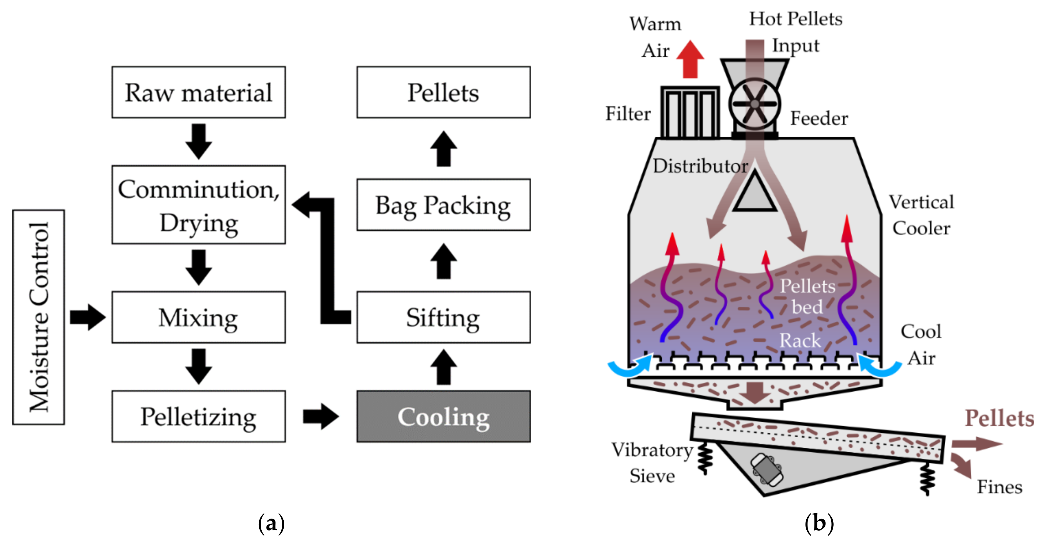
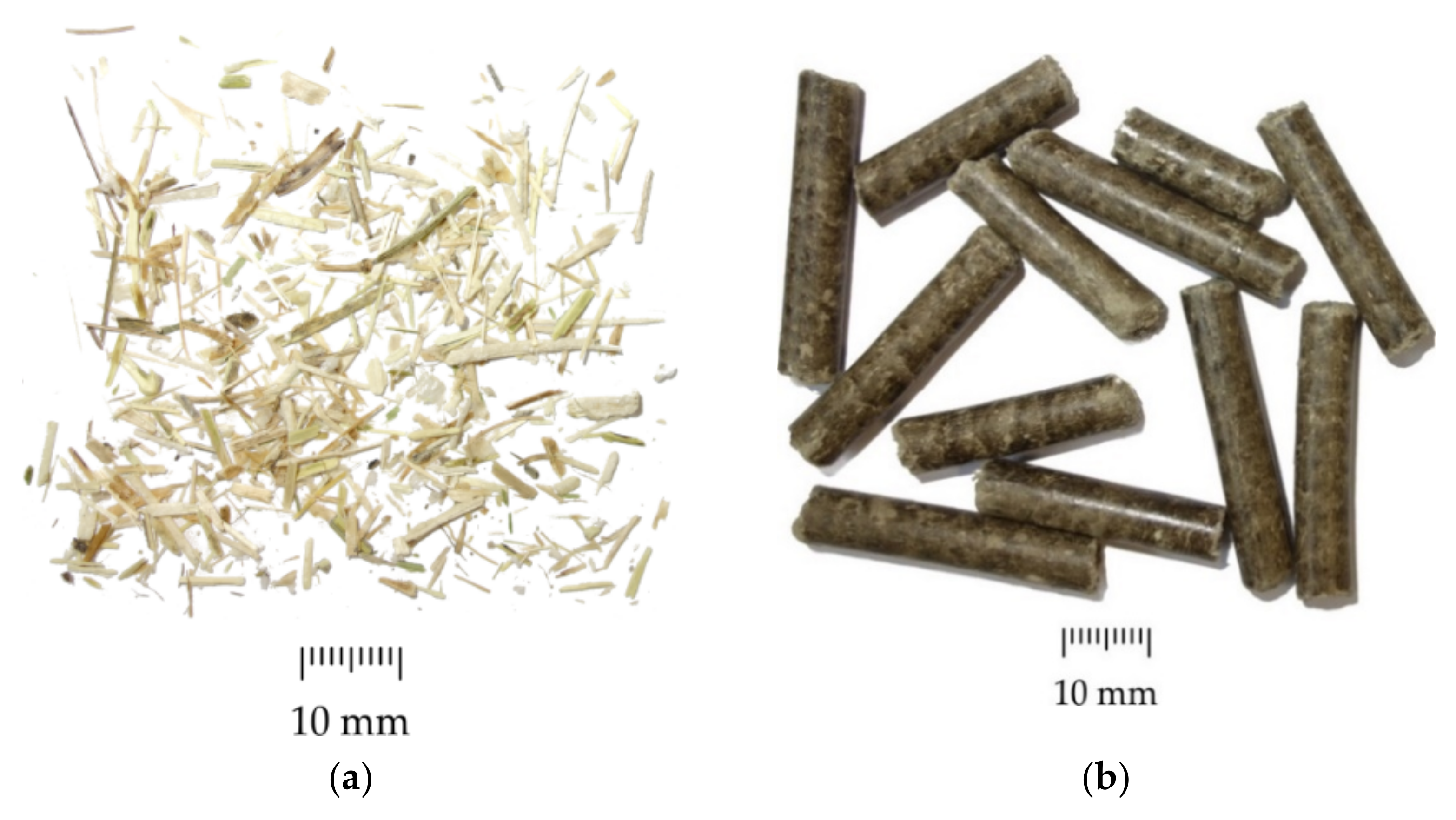
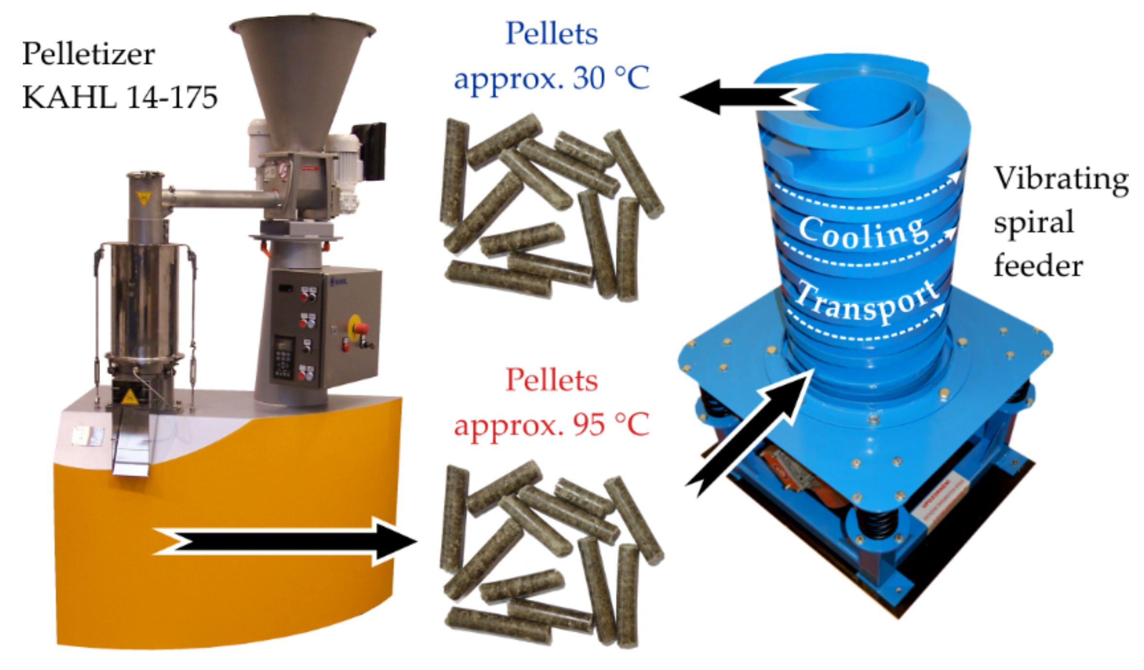
2. Materials and Methods

Pellets were produced from Odeon oilseed rape straw, which is produced as waste during the harvesting of oilseed rape seeds. It is a bred variety supplied by the seed company Oseva Pro. Oilseed rape is cultivated mainly to achieve higher yield, resistance and vitality of the variety.
At present, according to statistics from the Ministry of Agriculture in the Czech Republic, rapeseed is grown on an area of about 400,000 hectares of land [29]. It has a growing season of 300–350 days. After this, it is harvested, and what remains is the so-called rapeseed straw, which is biological rapeseed waste and which retains energy potential for further use. Therefore, it is important to address the possibilities of processing this type of bio waste.
Rapeseed straw was ground to a uniform particle size distribution using a Green Energy 9FQ 50 hammer mill, Green Energy Machinery Ltd., Uherský Brod, Czech Republic, (engine output 11 kW, mill capacity 800–1200 kg·h−1). It was also homogenized in a mixer called Alba Re 22, ALTESE Ltd., Hořovice, Czech Republic. This is a universal device for homogenizing mixtures of different compositions and materials. During homogenization, water was gradually added by spraying. The moisture level of the mixture was adjusted to 14%.
Rapeseed straw was pelleted in AMANDUS KAHL 14-175 (AMANDUS Ltd., Reinbek, Germany) laboratory rotary pelletizer with a flat matrix and 3 kW motor [30]. The flat matrix consists of a horizontal disk with holes with a diameter of 6 mm. A pair of rotating rollers pushes the raw material into the holes of the flat die, thus compacting and forming the final shape of the pellets. To illustrate, Figure 2 shows crushed rapeseed straw and the pellets produced.
The hot pellets coming out of the pelletizing press are fed directly to the inlet of the spiral vibrating trough. A spiral vibrating feeder was used to cool oilseed rape straw pellets. The cooling itself takes place during the transport of the pellets on the spiral trough of the vibrating feeder. The vibrating spiral trough causes the pellets to move upwards in a spiral due to micro-motions. The heat from the hot pellets is dissipated to the environment. The cooling efficiency of the hot pellets depends on the setting of the operating conditions of the spiral vibrating feeder and its construction. With a pair of vibromotors running, the vibrating unit produces a motion that consists of the amplitude of a rectilinear oscillating displacement (Az, m) in the direction of the Z axis and an oscillating angular rotation (φ’, °) around the Z axis (see Figure 3). Combining these two movements creates oscillations in the shape of a partial helix. The excitation force (FE, N) is perpendicular to the axis of the vibromotors and acts in the direction of the angle of rotation of the vibromotors (β, °) to the horizontal plane. The excitation force of vibromotors can be determined as the product of the square of the angular velocity of the vibromotor (ωv, s−1), the mass of the rotating eccentric weight (Ww, kg) and the radius of the center of gravity of the eccentric weight (R, m) from the vibrator axis (see Equation (1)). Figure 3 shows the location of a pair of vibromotors on a vibrating structure and the purpose of oscillation of the individual movements.
F E = ω v 2 × W w ×
Cooling during transport of pellets using micro vibrations is ensured by constant chaotic movement of individual pellets on a vibrating spiral trough. This allows the passage of air into the space between the individual pellets. In addition to the primary cooling, the pellets are transported to the desired height or space, where other sub-operations, such as dosing or packaging, can continue. The bottom of the spiral trough can be replaced in some sections with a perforated plate, through which dust and fines can fall and which can then be dispatched back to the beginning of the pelletization process. This can even replace another sieve operation. Figure 4 shows a process for the production and subsequent cooling of pellets by means of a spiral vibrating feeder.
Two variants of the construction of the spiral trough of the vibrating feeder were tested in pellet cooling experiments. The first design variant is a spiral trough of rectangular cross-section with dimensions of 60 × 25 mm (see Figure 5a). The length of the spiral path of the trough on the middle diameter (DT = 210 mm) is 5.9 m, and the transport height H is 0.5 m. The second variant of the construction consists of a basic spiral trough and a distribution of air hoses with holes. The air hose is located on the middle diameter of the spiral trough (DT = 210 mm). The openings in the air hoses allow cooling air to flow into the chute space. In this way, a more efficient entry of cooling air is ensured, which also penetrates the internal spaces between the individual pellets, and at the same time, the removal of warm air from the trough space is ensured. The location of the air hoses and the direction of the flowing cooling air are shown in Figure 5b.
The first part of the experimental study deals with the influence of setting operating parameters on the efficiency of transport of pellets made from rapeseed straw on a spiral vibrating feeder. The plan for the experimental tests was created to set the revolutions of the vibromotors n = 1800 rpm in combination with various settings of the oscillation amplitude of the spiral trough Az. The amplitude of the Az was adjusted by eccentric weight adjustment of each of the vibromotors to 60°, 90° and 120° (see Table 1).
The pellets were cooled in two basic design variants. The first instance involved direct cooling on the spiral trough of the vibrating feeder. In this case, the pellets are transported and spontaneously cooled at the same time. This is passive air cooling, which uses natural air circulation. The second setting was with the distribution of air hoses along the entire trajectory of the spiral trough. The pellets are cooled by flowing air from the hoses and at the same time transported to the packaging line, to the hopper, etc. This design uses active air cooling, when forced air circulation is created. Both variants were tested three times.
In both design variants, the pellet cooling process was always monitored by the FLIR-E60 thermal imager. The ambient temperature was 17 °C during measurement. A final operational setting of the oscillation amplitude was used for all tests Az120° = 0.48 mm.
The pellets were subjected to analyses based mainly on standardized quality standards for determining the properties and quality of the produced pellets. These were particle and bulk density of pellets [31,32,33], mechanical durability of pellets [34] and size of pellets.
The moisture content of all samples (input material of rapeseed, homogenized, pellets) was measured according to the standard ISO 18134-2:2017 [35]. Moisture reduction ratio MRR1—ratio of reduction of moisture content of rapeseed (moisture reduction ratio) (MRR1, %) is defined according to Equation (2), where MB is the moisture content of the produced pellets, and MS is the moisture content of the input sample of rapeseed straw.
M R R 1 = 1 M B M S × 100
Moisture reduction ratio MRR2—the moisture loss ratio of the pellets is analogously defined by Equation (3), where (MA, %) is the moisture content of the pellets after the cooling process on the spiral vibrating feeder and (MB, %) is the moisture of the pellets before the cooling process, i.e., the moisture of the pellets produced.
M R R 2 = 1 M A M B × 100
Particle density of pellets was determined on the Mettler Toledo JEW-DNY-43 tester, Mettler–Toledo Ltd., Prague, Czech Republic. Bulk density was determined according to the standard [32]. The values correspond to the average value from 5 measurements.
The pellets were subjected to a mechanical durability test on a Holmen NHP 100 tester, TEKPRO Ltd., Norfolk, UK. The tester works on the principle of circulation of 100.0 ± 0.5 g of pellets in a chamber where the pellets hit each other and the surrounding walls. The pellets durability index is expressed as the percentage weight loss of the test sample before and after the test process. The pellets circulated in the device for 60 s. The sample was sieved on a 3.15 mm sieve and then weighed. The test is repeated 5 times with various pellets and the average PDI value is calculated.
The size of the produced pellets was assessed mainly with respect to their possible degradation during the cooling process on a spiral vibrating feeder. In this analysis, the degree of influence of vibrations on the degradation of pellets was assessed. The pellets size was determined before entering the cooler and at its exit. A batch of approximately 150 pellets was used for determination of pellet size distribution before and after cooling process. Inlet and outlet of cooler were visually monitored. Record was used for pellet size determination. Outcoming pellets were arranged side by side, and the size was validated with a caliper [36].
High-speed camera—Olympus I-SPEED 2, iX Cameras Ltd., Rochford, UK. was used to measure the amplitude of movement of the vibrating spiral trough. The Olympus i-Speed 2 is a compact, mobile, autonomous color camera suitable for recording very fast and short-term, transient or random processes. The FLIR-E60 thermal camera, Teledyne FLIR Ltd., Wilsonville, OR, USA was used to monitor the temperature changes of the pellets during the cooling process on a spiral vibrating feeder. Thermal camera was used for determining of pellets temperature in time during the experiment. The FLIR-E60 has an IR sensor resolution of 320 × 240 points, a 25° lens field of view, manual focus and temperature measurement range from −20 °C to +650 °C. Temperature sensitivity of camera is 0.05 °C.

3. Results and Discussion

The section with the results was divided into three consecutive parts. The first part of the research was focused on monitoring the operating conditions of a spiral vibrating feeder designed for subsequent cooling of pellets. The second part was focused on a separate process of cooling pellets, and the analysis of pellets was performed from the point of view of controlling the influence of vibrations on the mechanical properties of pellets in the third part.

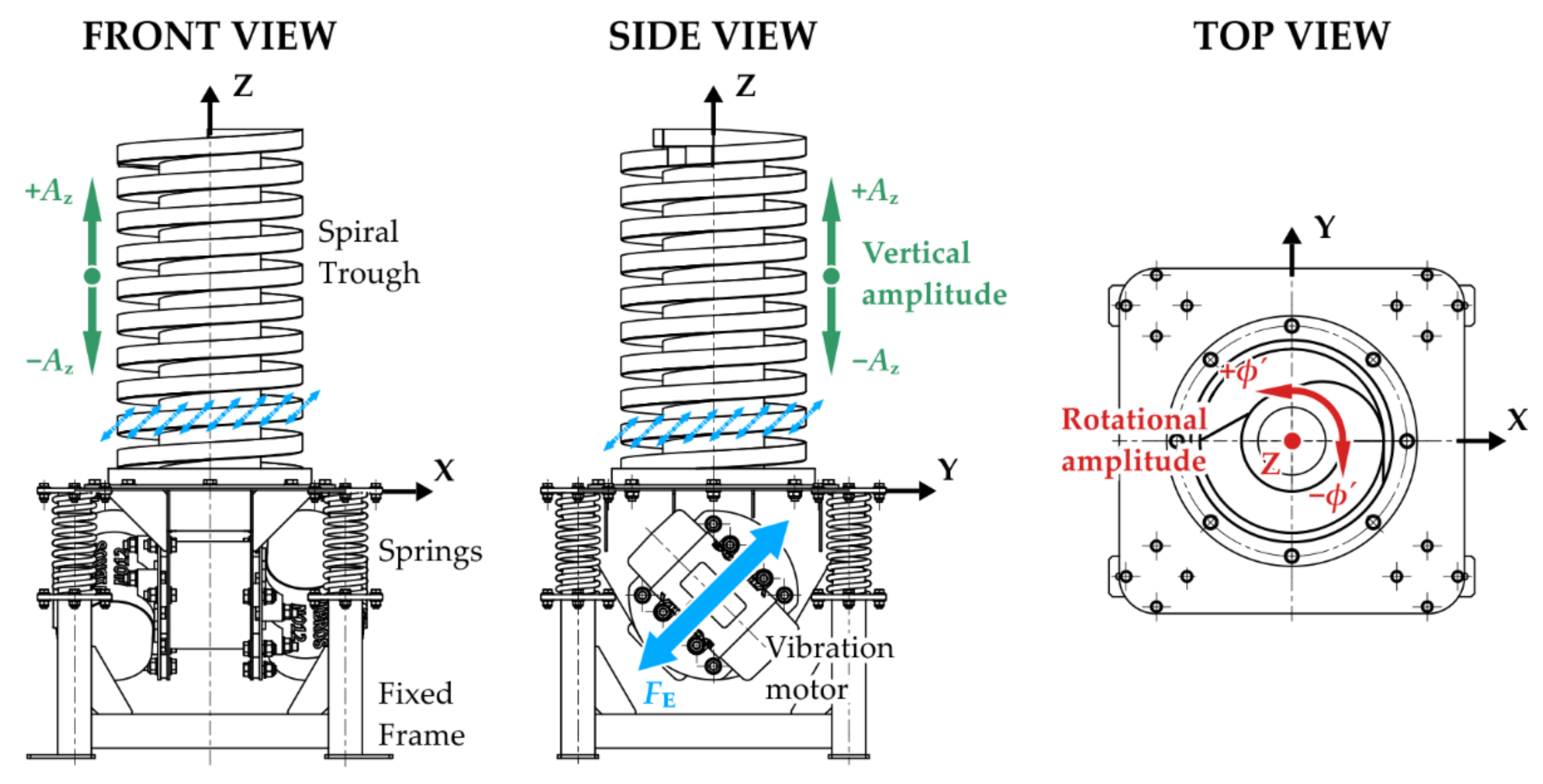
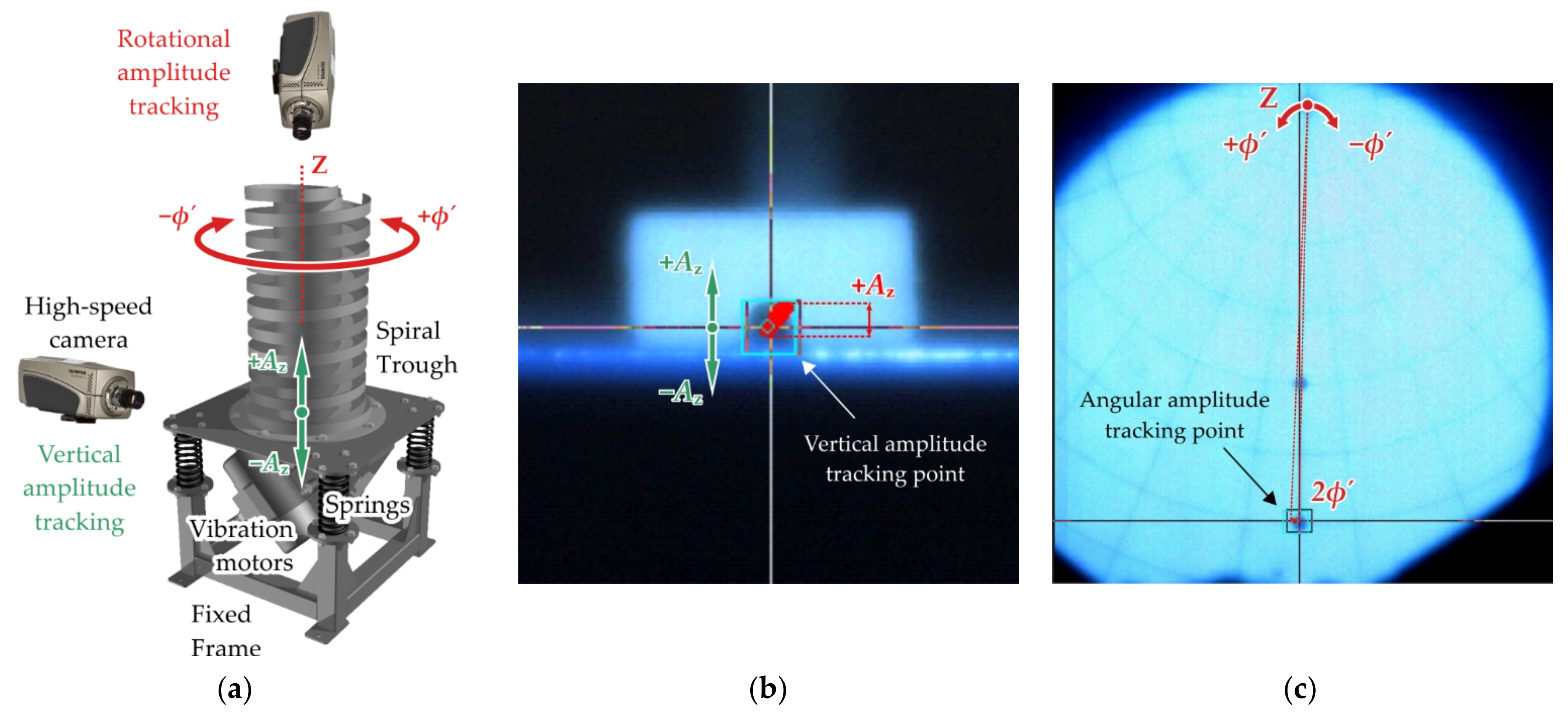
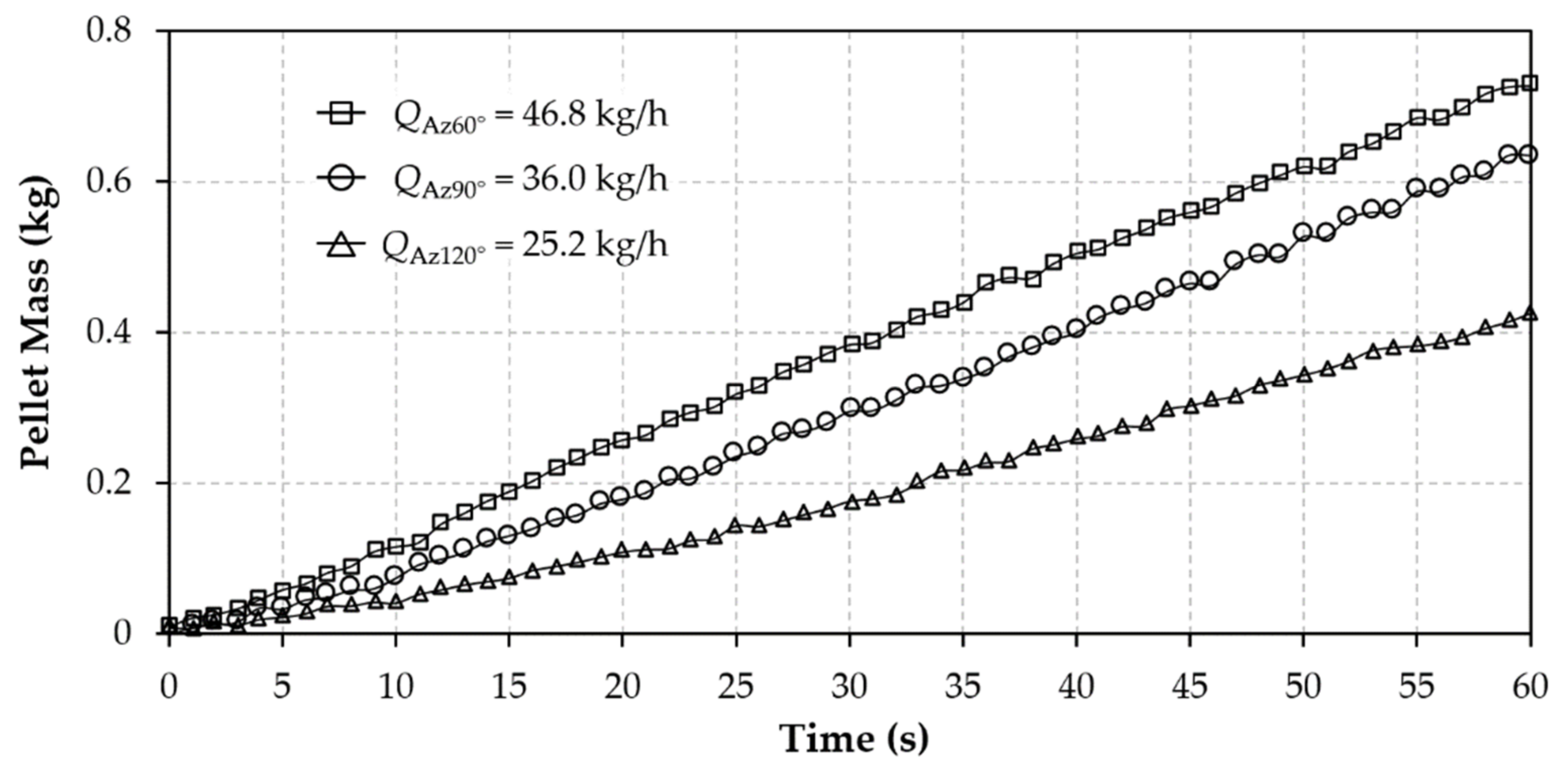
3.1. Optimizing Pellet Transport on a Spiral Vibrating Feeder
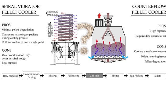
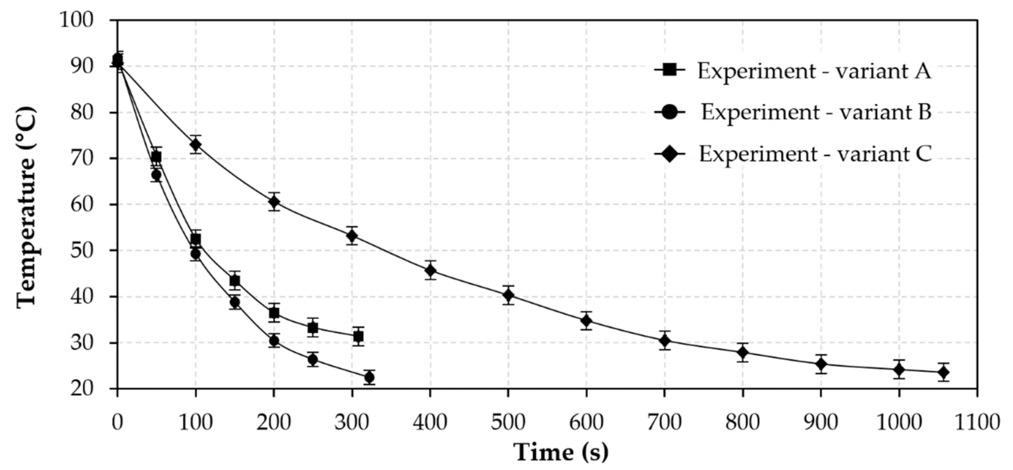
The monitored magnitudes of the vibration amplitude of the spiral trough are given in Table 1. The values given in Table 1 were obtained using a high-speed Olympus I-SPEED 2 camera and tracking software. The principle of amplitude measurement by tracing is shown in Figure 6.
Figure 7 shows cumulative weight of transported quantity of pellets over time as well as resulting mass flow rate Q (kg∙s−1) through the lab-scale spiral cooler depending on the operating setting of the oscillation amplitude.
For the subsequent transport and at the same time the process of cooling the pellets on the spiral vibrating feeder, the operating setting of the oscillation amplitude Az120° = 0.48 mm was chosen. At this setting, the transport of the pellets in the spiral trough had the longest duration. This parameter is essential for this type of cooling process, because the pellets are cooled individually, having been arranged side by side by the vibrations. The vibrations also increase the efficiency of the cooling process. Due to the vibrations of the spiral vibrating feeder, the pellets slowly change their position over time and gradually cool down. All pellets move at single layer on the spiral trough. Therefore, combination of parameters (length and width of trough, amplitude, frequency) gives a different mass flow and duration of the passage. Different needs can be met in this way.

3.2. Pellet Cooling

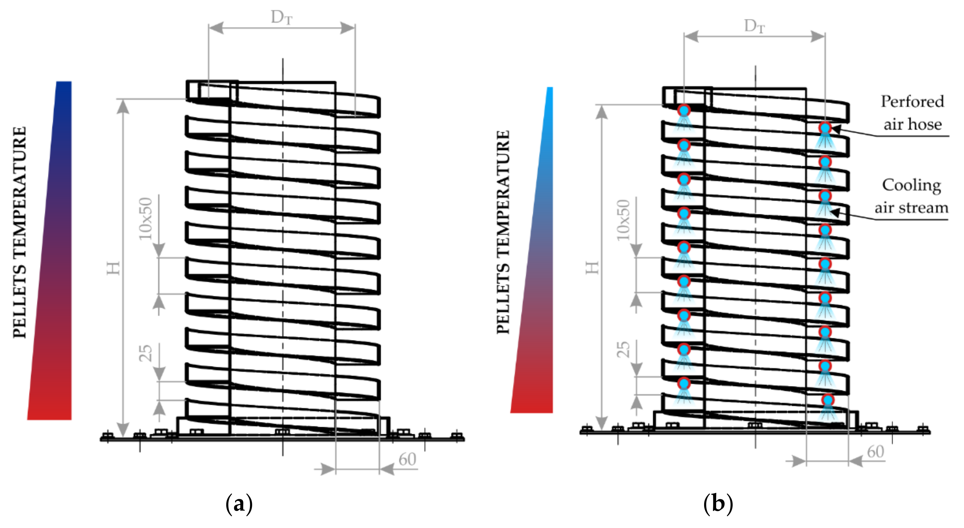
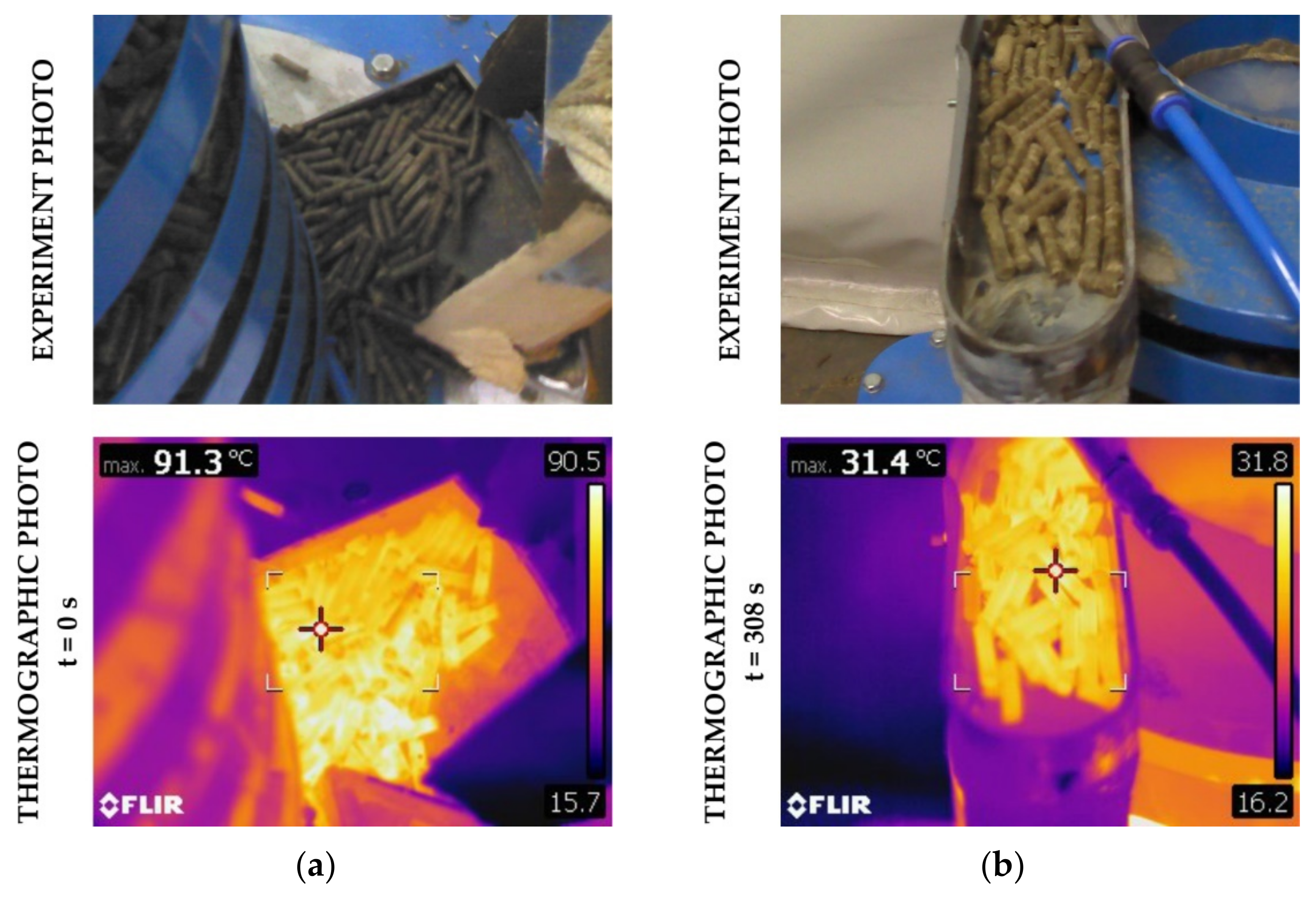
3.2.1. Cooling on a Spiral Trough (Variant A)

The spontaneous cooling of the pellets during their transport in the spiral vibratory feeder is shown in Figure 8 from the perspective of thermal imaging measurements. Figure 8a shows the entry of hot pellets into the spiral vibratory feeder and Figure 8b shows the output from the spiral vibratory feeder. In this case, measuring the temperature during the transport of the pellets is essential not only to determine the efficiency of the cooling process but also a prerequisite for evaluating the tested designs.
As can be seen from Figure 8a, the temperature of the pellets at the outlet of the pelletizing press was more than 91 °C. Temperature is one of the process parameters influencing pelletization. It can, of course, vary due to other parameters, such as the mechanical-physical properties of the input mixture, the geometry of the pelletizing press or the frequency of rotation of the pelletizing rollers. However, in the case of energy grass pellets, lignin acts as a natural binder in the temperature range of 75–120 °C (so-called glass transition temperature) and causes sufficient strength of the produced pellets [37]. For example, in wheat straw, the glass transition temperature is between 53–63 °C, but a pressing temperature above 100 °C is still recommended [38]. It can be seen from the thermo-images that the pellets did not exceed 100 °C. During transport in the spiral trough, the pellets were continuously cooled to a temperature of on average 31 °C (see Figure 8b). In the tested design—cooling on a spiral trough—it is a temperature drop of 60 °C on average in 308 s.

3.2.2. Cooling on the Spiral Trough with a Distribution of Air Hoses (Variant B)

During the transport and cooling of the pellets on the spiral trough with a distribution of air hoses, i.e., in the second design variant, temperature changes were also monitored using thermal imaging (see Figure 9).
During the tests, the rotation of the individual pellets was observed not only by vibrations caused by transport but also by the air flow from the air ducts. This should support the exchange of thermal energy and make it easier. Hot pellets were able to cool continuously from the mean value of original 91 °C to a final 22 °C in a period of 322 s. This represents a temperature difference of 69 °C.

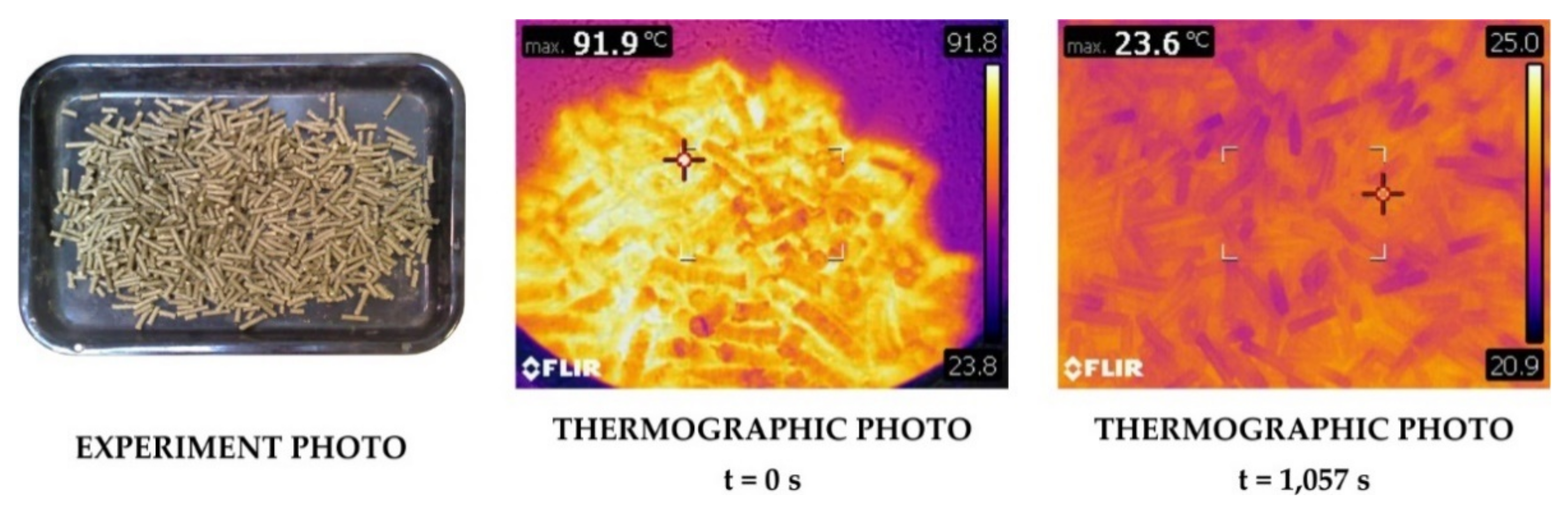
3.2.3. Cooling of Pellets on Free Surface (Variant C)

To compare the effects of vibrations on the pellet cooling process, three simple experiments were performed, in which samples of pellets coming from the pelletizing press were spread on a steel contact surface and allowed to cool spontaneously in an ambient temperature environment of 17 °C. These experiments were carried out in addition to, for example, laboratory conditions. Experiments show a comparison of the free cooling rate of pellets with the proposed system. The spiral vibrator pellet cooler described can be moved relatively easily and used for different types of pelleting presses. Figure 10 shows thermal images acquired during the spontaneous cooling of pellets. The hot pellets cooled on their own from an average original 90 °C to an average final 24 °C over a period of 1057 s. That is a temperature difference of 66 °C.
From the above-mentioned tested designs of pellet cooling (variants A and B) and spontaneous cooling of loose pellets (variant C), it is possible to observe differences in the cooling time of the pellets to a temperature suitable for their further processing. The use of vibrations to cool the pellets during transport has proven effective. The vibrations cause a slight rotation of the pellets; the pellets are spread side by side facilitating the exchange of thermal energy more easily than in a bed of pellets, as is the case in a countercurrent cooler. Using micro-vibration in a helix pattern, the pellets constantly move irregularly on the transport path, thus allowing cooler ambient air to enter the spaces between the pellets and at the same time to draw off the heated air. In addition, this positive effect can be amplified by the flow of cold air by means of distributed air hoses along the entire transport route (variant B). This method proved effective in the overall evaluation. Figure 11 shows the cooling curves of the design variants used (A, B) and the comparative spontaneous cooling of the pellets C.

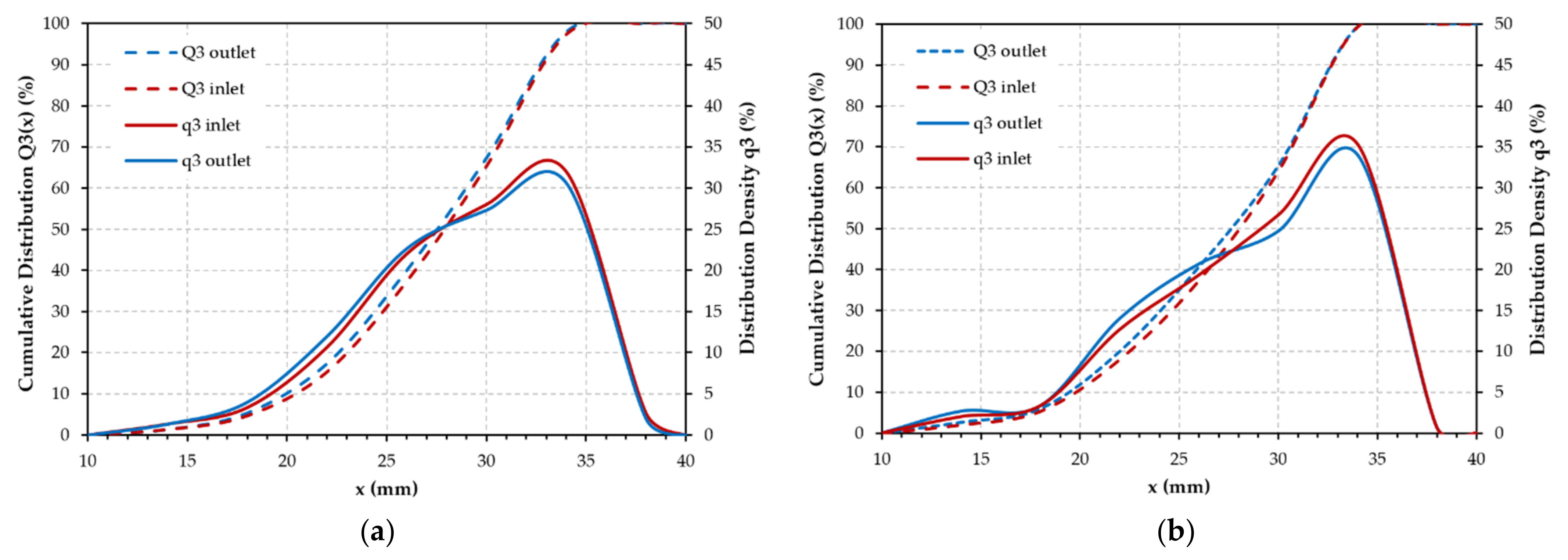
3.3. Mechanical Properties of Pellets

During the tests, samples of pellets were taken from various areas from different process points—after exiting the pelletizing press, prior to entry into the cooling device (input), after cooling in design variant of cooling system A (Aoutput), after cooling in the design variant B (Boutput) after cooling in the comparative spontaneous cooling of the pellets C (Coutput).
Bulk density was determined for all samples. One of the reasons for pelletization is the increase in bulk density due to the simplified processing, transport and storage of residual biomass [7,39]. Moreover, in the case of pelletization of rapeseed straw, as expected, there was an increase in bulk density. The values are given in Table 2.
All samples of pellets showed average bulk density values of 605–625 kg∙m−3, i.e., higher than the normative lower limit. It is clear that with decreasing moisture content, pellet bulk density also decreases. The specific gravity of the pellets can provide information on the burning efficiency of the pellets as well as information on their mechanical durability.
Figure 12 shows a comparison of the mechanical durability of pellets (PDI) for individual design variants of the cooling methods used (variants A and B) and the reference variant (variant C). All produced pellets were normatively compliant with PDI (PDI > 97.5% for class A herbaceous biomass pellets). The influence of the cooling method used is seen in variant B, when the PDI values reached a more significant increase in a relatively short time. No negative impact of vibrations to PDI value was occur.
During cooling, pellet firmness generally increases. This requires, among other things, certain deformation energy stored as a result of the palletization process. Prior to combustion, the pellets go through various transport and storage steps. They are often transported by pneumatically. They are subject to various loads and mechanical processes, leading to their abrasion, degradation and an increase in the proportion of fine dust. Pellet fragments can cause operational problems, such as system failure when draining pellet hoppers. Of course, the risk of dust explosion also increases and, during the combustion of degrading pellets, the increase in particulate emissions also increases [40]. Therefore, from the point of view of degradation of pellets, their size was assessed during the cooling process on a spiral vibrating feeder, for both construction design variants A and B.
The size of the produced pellets is assessed mainly from the point of view of possible degradation of the pellets during the cooling process on a spiral vibrating feeder. The particle size distribution results are shown in Figure 13. A batch of approximately 150 pellets was used for determination of pellet size distribution before and after cooling process.
The results show that no size degradation of the pellets occurs during the cooling process (see Figure 13). This method of cooling can contribute to minimizing the operational problems caused by the degradation resulting from the usual transport of the pellets. Vibration cooling is the so-called “two steps in one”, where they are also effectively cooled during the transport of the pellets. This innovative solution contributes to the trouble-free technology of producing alternative pellets.
The moisture reduction ratio MRR2 value can define the maximum humidity of the pellets entering the cooling system for the desired and suitable outlet moisture content of the pellets after the cooling process. MRR2 is an alternative to MRR1, which indicates the maximum moisture of the feedstock for the desired and suitable output moisture of the pellets for a given pellet press. In comparison with the literature data, we are in close agreement in the case of MRR1 with respect to the various tested materials. This ratio was 28% for vines, 16% for spruce sawdust and 59% for cork [41]. The MRR1 value for rapeseed straw is 23%.
The average value of the MRR2 moisture loss ratio for variant A, cooling on a spiral trough, was 40.3% and for variant B, cooling on a spiral trough with air hose distribution, was 34.7%. These ratios allow a practical estimation of the targeted moisture content of rapeseed straw pellets both for the MRR1 pelletization process and for the cooling process and their transport (MRR2).

4. Conclusions

A new system of cooling pellets on a spiral vibrating feeder was built in two design variants and practically tested. Both variants included the innovation “two steps in one”, where both the transport of pellets and their cooling take place in one step. Vibrational motion was used, where by means of helical micro vibrations, the pellets moved irregularly on the transport route, thus allowing cooler ambient air to enter the inter particle spaces and at the same time remove the heated air. In the first experimental part, the optimal operating conditions of the spiral vibrating feeder were determined. The optimal oscillation frequency of 30 Hz and the oscillation amplitude Az120° = 0.48 mm proved to be the most suitable for transporting and at the same time cooling the pellets on a spiral vibrating feeder. In the second experimental part, both variants of the structural arrangement of the spiral trough were tested. The first variant consists in cooling by chaotic movement of the pellets. The second then combines the chaotic movement of the pellets with the action of an intense air flow, using specially placed air hoses. Both variants were compared based on temperature changes, qualitative parameters of cooled pellets, degradation of pellets and moisture reduction ratio. The results confirmed that the use of both design variants is suitable for cooling pellets. No negative impact of vibrations to pellets size or PDI occurred. Pellets have sufficient mechanical durability after the cooling process. After the cooling process at the outlet of the spiral vibrating feeder, the pellets can be dosed directly into the prepared containers or packed. Variant B showed better results than variant A in terms of cooling efficiency, degradation and durability. Both design variants A and B were also compared with the cooling variant of bulk pellets. A summary of the advantages and disadvantages of the individual variants together with the countercurrent cooler are given in Table 3. The paper presents a new variation of pellet cooling system which can be chosen for transport during cooling in biomass pellets production systems as a different solution against counterflow cooler.

Author Contributions

Conceptualization, D.Ž. and L.J.; methodology, D.Ž. and L.J.; validation, D.Ž., L.J. and J.H.; formal analysis, D.Ž. and J.H.; investigation, D.Ž., L.J. and J.H.; writing—original draft preparation, D.Ž.; writing—review and editing, L.J., J.H. and J.D.; visualization, J.H.; supervision, J.Z.; project administration, J.N.; funding acquisition, J.N. and J.Z. All authors have read and agreed to the published version of the manuscript.

Funding

This paper was supported by the Ministry of Education, Youth and Sports of the Czech Republic under OP RDE grant number CZ.02.1.01/0.0/0.0/16_019/0000753 “Research centre for low-carbon energy technologies”. Work is also supported by Grant of DGS No. CZ.02.2.69/0.0/0.0/19_073/0016945 with sub-project No. DGS/TEAM/2020-003 “Research and development of innovative equipment for DEM simulations calibration and validation of particulate matter in the field of mechanical comminution processes and abrasion”.

Institutional Review Board Statement

Not applicable.

Informed Consent Statement

Not applicable.

Data Availability Statement

Not applicable.

Conflicts of Interest

The authors declare no conflict of interest.

Nomenclature/Abbreviations

AZZ direction amplitude(m)
AZ120°Z direction amplitude for vibration motors inclination of 120°(m)
DTtrough diameter(m)
FEexcitation force(N)
Hheight(m)
l0average pellet length before cooling process(m)
l1average pellet length after cooling process(m)
MApellets moisture after cooling process(%)
MBpellets moisture before cooling process(%)
MRRmoisture reduction ratio(-)
MSrape straw moisture(%)
nvibration motor revolutions(rpm)
PDIpellet durability index(%)
Qmass flow rate(kg∙s−1)
QAZ120°mass flow rate for vibration motors inclination of 120°(kg∙s−1)
QAZ60°mass flow rate for vibration motors inclination of 60°(kg∙s−1)
QAZ90°mass flow rate for vibration motors inclination of 90°(kg∙s−1)
Rradius(m)
ttime(s)
Wwmass of eccentric weights(kg)
XX axis direction(-)
YY axis direction(-)
ZZ axis direction(-)
φ´angular amplitude(°)
βinclination of vibration motors(°)
ρdensity(kg∙m−3)
ρBbulk density(kg∙m−3)
ωvvibration motor angular velocity(s−1)
Aoutletpellets cooling process outlet of A construction design
Boutletpellets cooling process outlet of B construction design
Coutletpellets cooling process outlet of C construction design
MRRmoisture reduction ratio
PDIpellet durability index

References

  1. Holm-Nielsen, J.B.; Ehimen, E.A. Biomass Supply Chains for Bioenergy and Biorefining, 1st ed.; Elsevier: Amsterdam, The Netherlands, 2016. [Google Scholar]
  2. Maier, D.E.; Bakker-Arkema, F.W. The Counterflow Cooling of Feed Pellets. J. Agric. Eng. Res. 1992, 53, 305–319. [Google Scholar] [CrossRef]
  3. Thomas, M.; Van Zuilichem, D.J.; Van Der Poel, A.F.B. Physical Quality of Pelleted Animal Feed. 2. Contribution of Processes and its Conditions. Anim. Feed Sci. Technol. 1997, 64, 173–192. [Google Scholar] [CrossRef]
  4. Tumuluru, J.S.; Wright, C.T.; Hess, J.R.; Kenney, K.L. A Review of Biomass Densification Systems to Develop Uniform Feedstock Commodities for Bioenergy Application. Biofuels Bioprod. Biorefining 2011, 5, 683–707. [Google Scholar] [CrossRef]
  5. Arshadi, M.; Gref, R.; Geladi, P.; Dahlqvist, S.A.; Lestander, T. The Influence of Raw Material Characteristics on the Industrial Pelletizing Process and Pellet Quality. Fuel Process. Technol. 2018, 89, 1442–1447. [Google Scholar] [CrossRef]
  6. Nielsen, N.P.K.; Gardner, D.J.; Poulsen, T.; Felby, C. Importance of Temperature, Moisture Content, and Species for the Conversion Process of Wood Residues into Fuel Pellets. Wood Fiber Sci. 2009, 41, 414–425. [Google Scholar]
  7. Miranda, M.T.; Sepúlveda, F.J.; Arranz, J.I.; Montero, I.; Rojas, C.V. Analysis of Pelletizing from Corn Cob Waste. J. Environ. Manag. 2018, 228, 303–311. [Google Scholar] [CrossRef]
  8. Gil, M.; Arauzo, I.; Pelet, I.C.A. Hammer Mill Operating and Biomass Physical Conditions Effects on Particle Size Distribution of Solid Pulverized Biofuels. Fuel Process. Technol. 2014, 127, 80–87. [Google Scholar] [CrossRef]
  9. Labbé, R.; Paczkowski, S.; Knappe, V.; Russ, M.; Wöhler, M.; Pelz, S. Effect of Feedstock Particle Size Distribution and Feedstock Moisture Content on Pellet Production Efficiency, Pellet Quality, Transport and Combustion Emissions. Fuel 2020, 263, 116662. [Google Scholar] [CrossRef]
  10. Lyu, F.; Thomas, M.; Hendriks, W.H.; Van der Poel, A.F.B. Size Reduction in Feed Technology and Methods for Determining, Expressing and Predicting Particle Size: A Review. Anim. Feed Sci. Technol. 2020, 261, 114347. [Google Scholar] [CrossRef]
  11. Kaliyan, N.; Morey, R.V. Densification Characteristics of Corn Cobs. Fuel Process. Technol. 2010, 91, 559–565. [Google Scholar] [CrossRef]
  12. Rezaei, H.; Yazdanpanah, F.; Lim, C.J.; Sokhansanj, S. Pelletization Properties of Refuse-Derived Fuel-Effects of Particle Size and Moisture Content. Fuel Process Technol. 2020, 205, 106437. [Google Scholar] [CrossRef]
  13. Jezerska, L.; Drozdova, J.; Rozbroj, J.; Zegzulka, J.; Frydrych, J. Pelletization of Energy Grasses: A study on the Influence of Process and Material Parameters on Pellet Quality. Int. J. Green Energy 2019, 16, 1278–1286. [Google Scholar] [CrossRef]
  14. Jezerska, L.; Zegzulka, J.; Palkovska, B.; Kucerova, R.; Zadrapa, F. Pelletization of Invasive Reynoutria Japonica with Spruce Sawdust for Energy Recovery. Wood Res. 2018, 63, 1045–1058. [Google Scholar]
  15. Lehtikangas, P. Quality Properties of Pelletised Sawdust, Logging Residues and Bark. Biomass Bioenergy 2015, 50, 351–360. [Google Scholar] [CrossRef]
  16. Miranda, T.; Montero, I.; Sepúlveda, F.J.; Arranz, J.I.; Rojas, C.V.; Nogales, S. A review of Pellets from Different Sources. Materials 2015, 8, 1413–1427. [Google Scholar] [CrossRef] [Green Version]
  17. Pradhan, P.; Mahajani, S.M.; Arora, A. Production and Utilization of Fuel Pellets from Biomass: A review. Fuel Process. Technol. 2018, 181, 215–232. [Google Scholar] [CrossRef]
  18. Döring, S. Power from Pellets: Technology and Applications; Springer: Berlin, Germany, 2013. [Google Scholar]
  19. Machinery Amisy Pellet, n.d. Biomass Pellet Plant. Available online: https://www.pellet-plant.net/ (accessed on 23 June 2020).
  20. Obernberger, I.; Thek, G. The Pellet Handbook: The Production and Thermal Utilisation of Biomass Pellets; Earthscan Ltd.: London, UK, 2010. [Google Scholar]
  21. Tumuluru, J.S. Effect of process variables on the density and durability of the pellets made from high moisture corn stover. Biosyst. Eng. 2014, 119, 44–57. [Google Scholar] [CrossRef] [Green Version]
  22. Vekamaf Services, B.V., n.d. Feed and Biomass Installations and Equipment. Available online: https://www.vekamaf.com/industry/feed-and-biomass/ (accessed on 28 May 2021).
  23. Rosentrater, K.A.; Evers, A.D. Kent’s Technology of Cereals an Introduction for Students of Food Science and Agriculture; Woodhead Publishing: Cambridge, UK, 2018. [Google Scholar]
  24. Behnke, K.C. Feed manufacturing technology: Current Issues and Challenges. Anim. Feed Sci. Technol. 1996, 62, 49–57. [Google Scholar] [CrossRef]
  25. Spinelli, R.; Cavallo, E.; Eliasson, L.; Facello, A.; Magagnotti, N. The Effect of Drum Design on Chipper Performance. Renew. Energy 2015, 81, 57–61. [Google Scholar] [CrossRef]
  26. Warguła, Ł.; Krawiec, P.; Waluś, K.J.; Kukla, M. Fuel Consumption Test Results for a Self-Adaptive, Maintenance-Free Wood Chipper Drive Control System. Appl. Sci. 2020, 10, 2727. [Google Scholar] [CrossRef] [Green Version]
  27. Warguła, Ł.; Kukla, M.; Lijewski, P.; Dobrzyński, M.; Markiewicz, F. Influence of Innovative Woodchipper Speed Control Systems on Exhaust Gas Emissions and Fuel Consumption in Urban Areas. Energies 2020, 13, 3330. [Google Scholar] [CrossRef]
  28. Spinelli, R.; Eliasson, L.; Magagnotti, N. Increasing Wood Fuel Processing Efficiency by Fine-Tuning Chipper Settings. Fuel Process. Technol. 2016, 151, 126–130. [Google Scholar] [CrossRef]
  29. Liška, M. Situation and Outlook Report of the Oilseed; Ministry of Agriculture: Prague, Czech Republic, 2017. [Google Scholar]
  30. Jezerska, L.; Zajonc, O.; Zegzulka, J.; Kovalova, L.; Janouchova, R. Mechanical Material Properties effect on Pelletization. Proceedings of 21st International Congress of Chemical and Process Engineering CHISA 2014 and 17th Conference on Process Integration, Modelling and Optimisation for Energy Saving and Pollution Reduction PRES 2014, Prague, Czech Republic, 23–27 August 2014; p. 1061. [Google Scholar]
  31. ISO 18847:2016. Solid biofuels-Determination of Particle Density of Pellets and Briquettes; ISO: Geneva, Switzerland, 2016. [Google Scholar]
  32. ISO 17828:2015. Solid Biofuels-Determination of Bulk Density; ISO: Geneva, Switzerland, 2015. [Google Scholar]
  33. Rabier, F.; Temmerman, M.; Böhm, T.; Hartmann, H.; Daugbjerg Jensen, P.; Rathbauer, J.; Carrasco, J.; Fernández, M. Particle Density Determination of Pellets and Briquettes. Biomass Bioenergy 2006, 30, 954–963. [Google Scholar] [CrossRef]
  34. ISO 17831-1:2015. Solid biofuels-Determination of Mechanical Durability of Pellets and Briquettes 30-Part 1: Pellets; ISO: Geneva, Switzerland, 2015. [Google Scholar]
  35. ISO 18134-2:2017. Solid biofuels -Determination of Moisture Content-Oven Dry Method-Part 2: Total Moisture-Simplified Method; ISO: Geneva, Switzerland, 2017. [Google Scholar]
  36. ISO 17829:2015. Solid Biofuels-Determination of Length and Diameter of Pellets; ISO: Geneva, Switzerland, 2015. [Google Scholar]
  37. Gilbert, P.; Ryu, C.; Sharifi, V.; Swithenbank, J. Effect of Process Parameters on Pelletisation of Herbaceous Crops. Fuel 2009, 88, 1491–1497. [Google Scholar] [CrossRef]
  38. Whittaker, C.; Shield, I. Factors Affecting Wood, Energy Grass and Straw Pellet Durability-A review. Renew. Sustain. Energy Rev. 2017, 71, 1–11. [Google Scholar] [CrossRef]
  39. Stelte, W.; Holm, J.K.; Sanadi, A.R.; Barsberg, S.; Ahrenfeldt, J.; Henriksen, U.B. A Study of Bonding and Failure Mechanisms in Fuel Pellets from Different Biomass Resources. Biomass Bioenergy 2011, 35, 910–918. [Google Scholar] [CrossRef] [Green Version]
  40. Jägers, J.; Wirtz, S.; Scherer, V.; Behr, M. Experimental Analysis of Wood Pellet Degradation during Pneumatic Conveying Processes. Powder Technol. 2020, 359, 282–291. [Google Scholar] [CrossRef]
  41. Mediavilla, I.; Fernández, M.J.; Esteban, L.S. Optimization of Pelletisation and Combustion in a Boiler of 17.5 kWth for Vine Shoots and Industrial Cork Residue. Fuel Process. Technol. 2009, 90, 621–628. [Google Scholar] [CrossRef]
Figure 1. Pellets production and cooling: (a) pellets production process scheme; (b) counterflow pellet cooling system.
Processes 09 01060 g001
Figure 2. Biomass samples: (a) comminuted rape straw; (b) rape straw pellets.
Processes 09 01060 g002
Figure 3. Schematic drawing of the placement of a pair of vibromotors and the purpose of the oscillation of individual movements.
Processes 09 01060 g003
Figure 4. Schematic of production process—pelletizing and cooling of pellets via vibrating spiral feeder.
Processes 09 01060 g004
Figure 5. Variants of construction arrangement: (a) Variant A—spiral trough; (b) Variant B—spiral trough with perforated air hose cooling system.
Processes 09 01060 g005
Figure 6. Spiral trough movement amplitudes tracking: (a) measurement scheme; (b) vertical amplitude AZ tracking; (c) angular amplitude φ´ tracking.
Processes 09 01060 g006
Figure 7. Cumulative weight of cooled pellets in time and mass flow rate Q (kg∙s−1) depending on eccentric weight adjustment.
Processes 09 01060 g007
Figure 8. Selected thermographic photos made during cooling process via variant A spiral vibrator: (a) inlet; (b) outlet.
Processes 09 01060 g008
Figure 9. Selected thermographic photos made during cooling process via variant B spiral vibrator with perforated air hose cooling system: (a) inlet; (b) outlet.
Processes 09 01060 g009
Figure 10. Thermographic photos made during spontaneous cooling on free surface.
Processes 09 01060 g010
Figure 11. Cooling curves for experiment variants A–C.
Processes 09 01060 g011
Figure 12. PDI values comparison before and after cooling for variants A–C.
Processes 09 01060 g012
Figure 13. Pellets size change during cooling process: (a) Variant A; (b) Variant B.
Processes 09 01060 g013
Table 1. Vertical and angular amplitudes values for vibration motors revolutions of n = 1800 rpm.
Processes 09 01060 i001Processes 09 01060 i002Processes 09 01060 i003
Eccentric Weight Adjustment (°)6090120
Vibration motor centrifugal force (N)850693489
Vertical amplitude Az (mm)0.850.630.48
Angular amplitude φ´ (°)0.240.240.18
Table 2. Particle and bulk density of raw material and pellets before and after cooling process.
ρ (kg∙m−3)ρB (kg∙m−3)
Raw material—Rape straw-127.2 ± 4.5
Cooler inlet1320 ± 16625.0 ± 2.8
Cooler outlet—variant Aoutlet1321 ± 18615.1 ± 3.0
Cooler outlet—variant Boutlet1345 ± 10610.7 ± 3.2
Cooler outlet—variant Coutlet1321 ± 9605.8 ± 3.6
Table 3. Various cooling systems comparison.
Cooling VariantAdvantagesDisadvantages
ACooling of every single pellet,
low energy consumption,
handling coupled with cooling process,
no air distribution requirements,
easy process setup
A little bit slower cooling process,
water condensation may occur in spiral trough
BCooling of every single pellet,
handling coupled with cooling process after pellets production,
easy process setup
Noise (extra air flow),
high energy consumption,
air distribution requirements
CNo investment,
no air distribution requirements
Very slow cooling process,
space requirements, pilot-plant use only
Counterflow coolerHigh capacityInhomogeneous cooling process, noise, pellets jamming, pellets degradation, investment, space requirements,
air distribution requirements
Publisher’s Note: MDPI stays neutral with regard to jurisdictional claims in published maps and institutional affiliations.

