Article

Development of an Impregnation End-Effector with Fiber Tension Monitoring for Robotic Coreless Filament Winding

1
Institute for Textile and Fiber Technologies, University of Stuttgart, Pfaffenwaldring 9, 70569 Stuttgart, Germany
2
Institute for Computational Design and Construction, University of Stuttgart, Keplerstraße 11, 70174 Stuttgart, Germany
3
German Institutes of Textile and Fiber Research Denkendorf, Körschtalstraße 26, 73770 Denkendorf, Germany
*
Author to whom correspondence should be addressed.
Processes 2021, 9(5), 806; https://doi.org/10.3390/pr9050806
Submission received: 17 April 2021 / Revised: 26 April 2021 / Accepted: 30 April 2021 / Published: 4 May 2021
(This article belongs to the Section Manufacturing Processes and Systems)

Abstract

:
The manufacturing process of robotic coreless filament winding has great potential for efficient material usage and automation for long-span lightweight construction applications. Design methods and quality control rely on an adequate digital representation of the fabrication parameters. The most influencing parameters are related to the resin impregnation of the fibers and the applied fiber tension during winding. The end-effector developed in this study allows efficient resin impregnation, which is controlled online by monitoring the induced fiber tension. The textile equipment was fully integrated into an upscaled nine-axis robotic winding setup. The cyber-physical fabrication method was verified with an application-oriented large-scale proof-of-concept demonstrator. From the subsequent analysis of the obtained datasets, a characteristic pattern in the winding process parameters was identified.

1. Introduction

In lightweight construction applications, carbon and glass fiber-reinforced plastics (C/GFRPs) offer specific advantages over many conventional structural material systems, such as those that rely on steel and aluminum. C/GFRPs result in more design freedom, higher specific mechanical performance, higher corrosive resistance, and low thermal expansion. Furthermore, on-site fabrication results in decreased transport costs and limitations. In comparison with steel cables, the stiffness- and strength-to-density ratios of CFRP cables are 4.5 and 7.4 times higher [1], and the specific strength of unidirectional carbon fibers is up to 8.2 times higher [1]. However, due to their orthotropy, C/GFRPs require different methods of load transmission and design [2,3]. In addition to the component shape, loading situation, and force transmission, the structural performance of a fiber-reinforced component is largely defined by its fiber orientation [4], impregnation quality [5], and fiber tension [6].
Coreless filament winding (CFW) makes optimum use of the properties of C/GFRPs. CFW is a textile additive manufacturing process for integral fiber-reinforced load-bearing lattice composite structures. Fibers, impregnated with a thermoset resin, span freely in space and are hooked around spatially arranged pins in a specific order. A frame holds the winding pins in position but has no contact with the composite itself.
The sequence in which the fiber bundle is hooked around the winding pins is called the winding syntax [7]. Placing each fiber bundle individually allows full control over the component geometry and fiber orientation. After the last winding session is completed, the composite component emerges after the resin is cured. Winding preparation requires frame assembly, calibration of the robotic system, and resin mixing. Post-processing includes tempering, removing imperfections, brushing, visual inspections, demolding the self-supporting component from the frame, and weighing it. Ancillary operations remain largely manual, whereas the winding process step was fully automated. Robotic coreless filament winding (RCFW) is the only feasible method for large-scale components because of the fiber tension and duration of winding sessions. For small-scale components, it should only be used if the production quantities justify the automation effort. RCFW relies on automation and digitalization, which increases productivity, making the process beneficial for construction applications and the management of supply–demand chains.
CFW can be seen as an extension of conventional filament winding [8,9]. Here, rovings are placed onto the continuous surface of a mandrel or mold. The created composite shells are reliant on the surface quality of the mold and also inherit its disadvantages, such as high investment cost, large mass, and small tolerances, combined with its sensitive surfaces, the need for release agents, and additional load transmission elements. Furthermore, there is no adaptability that permits component geometries to be altered.
CFW is often compared to tape laying processes [10,11], in which, usually, thermoplastic tapes are discontinuously placed with a specific orientation in multiple stacks onto a planar mold. In the field of additive manufacturing, CFW competes with the layer-based FDM printing process [12,13,14] of thermoplastics with embedded continuous fiber reinforcement. In this case, the component size is too limited for construction applications, and fiber reinforcement cannot by generated across layers. Another variant of RCFW with an industrial application is a process used to fabricate the inner structure of wind turbine blades [15].
In state-of-the-art RCFW setups [16,17], a stationary industrial robot with one (one-axis-positioner) or two (turn-tilt-table) additional axes is used. Alternatively, multiple robots can be used [18]. The fibers are impregnated remotely by a resin bath and then run freely to the robot end-effector [19], which usually consists of a metallic ring to catch the fibers and a nozzle to position the fiber bundles [20]. The drawbacks that characterize such equipment include dripping resin from traveling impregnated fibers and potential points of contact that can damage fiber rovings. State-of-the-art CFW systems do not contain any sensors, but tension monitoring has been performed on stationary machines for conventional filament winding [21,22] and on dry yarns [23,24].
In recent research [25,26,27] on RCFW, the effectiveness of the frame was successively improved to decrease tooling costs and increase the adaptivity of the building system. As a by-product, composite structures are increasingly form-defined by fiber–fiber interactions; thus, any geometrical simulation of the composite requires knowledge about the induced fiber tension. For structural simulations, one of the most important factors is the fiber volume ratio (FVR) of the composite [28]. Performing simulations in the design process is a prerequisite for the broad industrial utilization of RCFW. The motivation for the design of the end-effector was to reduce uncertainties in the impregnation and fiber tension.
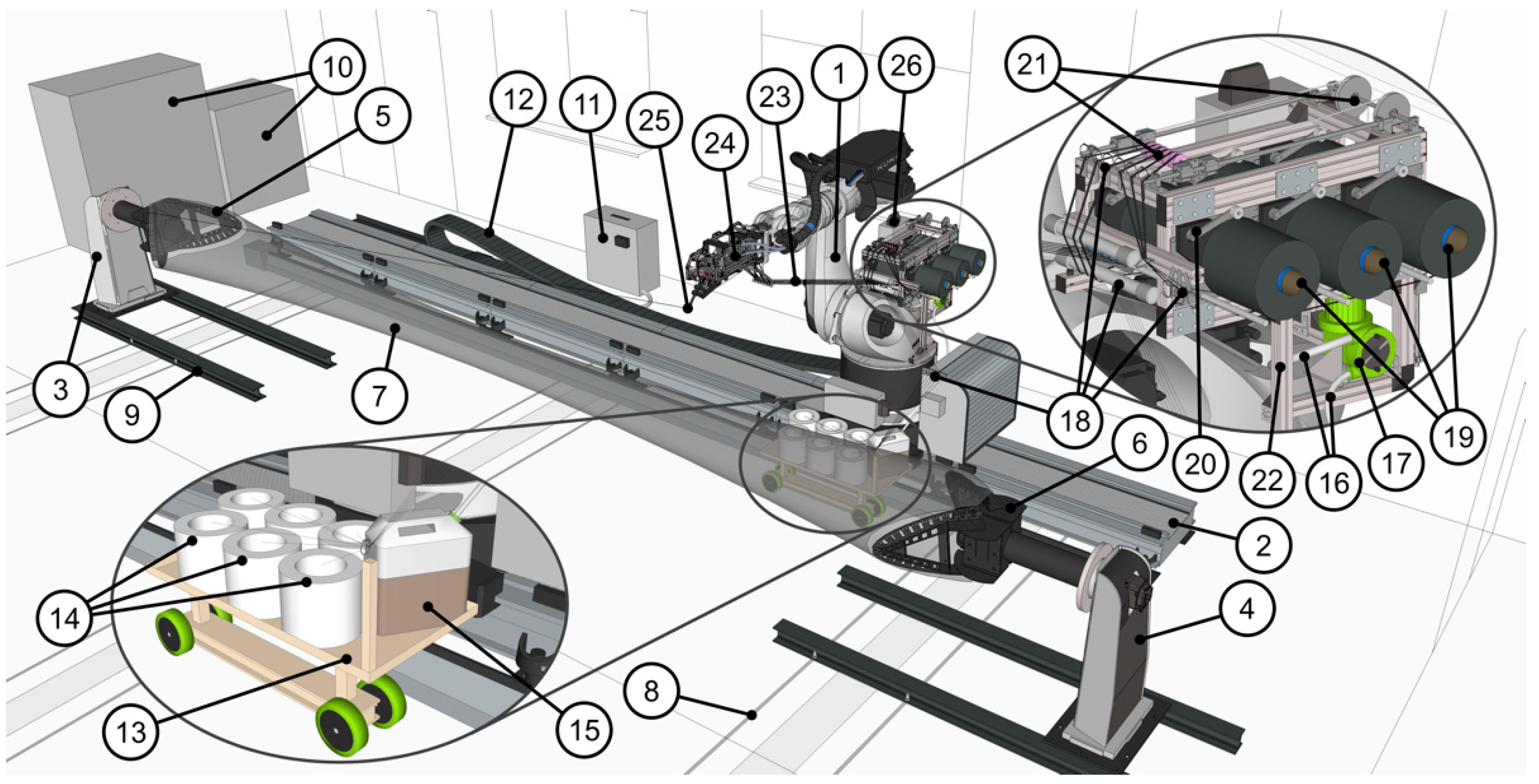
The objective of the presented research was to develop a cyber-physical 9-axis RCFW production setup (Figure 1), including an impregnation end-effector with built-in tension monitoring capability. The setup is self-sufficient, compact, sensor-controlled in real time, and capable of producing upscaled components and capturing production data to generate a more holistic digital twin and perform quality control.

2. Materials and Methods

The presented RCFW process consists of a strongly interlinked cyber-physical procedure. Initially, the digital process involves component design [3], fiber syntax creation [29], structural simulation [30], and machine control aspects [31]. The syntax of the tubular hyperboloid fiber lattice shape of the component consists of several layers, which are functionally and geometrically differentiated.

2.1. Large-Scale Cyber-Physical Winding Setup

The physical fabrication setup (Figure 1) had to be arranged, and the digital model (Figure 2) must match it. In RCFW, the fiber dispenser or the winding frames can be attached to the robot(s) or additional axes. The best configuration is influenced by the tool dimensions and masses, as well as the number and work envelope of the robot(s). Attaching both tools to industrial robots adds automation complexity but offers the highest level of geometrical freedom.
The main element of the setup is an industrial robot [32] mounted on a 10 m long linear track [33] (pp. 18–19). This system was extended by an external horizontal rotational axis in the form of two active positioners [33] (pp. 32–33) fitted with custom cylindrical metallic flanges. These flanges carry two metallic modular winding frames, each equipped with 48 metallic washer/sleeve winding pins.
This external kinematic system was integrated into the controller of the robot manipulator, following a primary/secondary configuration. The 9-axis kinematic system was calibrated to millimeter precision, which was verified through test-winding sequences performed with un-impregnated fibers. After calibration, the tool center point (TCP) working range of the robotic system corresponds to a 16 × 5 × 5 m3 (L × W × H) volume, which was digitally limited to a 12 × 5 × 5 m3 volume due to spatial constraints. The additional axis can rotate the component around its cylindrical main axial direction, and the linear track can shift the robot to increase reachability. The integrated kinematic system is numerically and interactively controlled by a panel or via a visual application.
A prerequisite for the deployment of the winding end-effector, described in Section 2.3, was the integration of additional textile equipment (fiber and resin source, pump and tension control system) into the robotic manufacturing setup. Carbon fiber spools are housed within a creel mounted on the robot carousel, whereas the larger glass fiber bobbins are carried by a mobile platform in front of the robot.
A passive mechanical tension control unit is located above the creel, and a peristaltic pump is placed underneath it. The pump supplies mixed epoxy resin to impregnation chambers in the end-effector via a tube. Together with the sensor cable, it was routed through the robot power supply hose. This ensures that only dry fiber bundles span between the end-effector and the robot platform. Downsizing all of these components into a restricted volume on a dynamic moving system is regarded as a prerequisite for the production of large-scale components, which requires the robot to move on tracks.

2.2. Sensor-Supported Control through Feedback Loops

The TCP velocity and the pump are controlled by two interdependent, system-integrated, automated feedback loops. The velocity of the TCP is adjusted in reciprocal proportion to the measured fiber tension in real time. The parameters for the tension–velocity feedback loop were experimentally determined and coordinated safely within the range of the robot’s test operation mode. The aim is to minimize fluctuations in the fiber deposition and tension. If the tension exceeds a threshold, the robot stops so that operators can check and solve malfunctions before they affect the quality of the composite, ensuring that it remains within geometric tolerances. This level of adaptive control is especially necessary for the production of large-scale components: since the cost and effort per iteration is high, adjustments should be made as promptly as possible during the winding process. Online quality control also prevents the tearing of fibers, which was previously a safety issue for operators. The resin volume flow is also controlled in real time by another feedback loop. The necessary resin volume flow proportionally increases with the TCP velocity. At a standstill, the resin volume flow is equal to the leakage. The parameters of the dependencies between the TCP velocity and the pump were pre-calculated based on the calibration of the pump and the theoretical resin consumption per fiber length, including an estimated leakage rate. The values can be adjusted during production to immediately adapt to influences not only between iterations.
The parametric robot control code was generated offline in a CAD interface [34] augmented with a visual programming software [35] supporting additional programming in Python and C#. The code structure is modular: instructions pertaining to hooking and spanning motions are separately generated based on geometry of the setup and the winding syntax. After procedural and visual checks of the winding feasibility, the winding sequences are compiled into a robot control module [36]. Once uploaded to the robot controller, the online data coming from the tension sensor can be accessed in the code, which enables the sensor-supported control of the robotic motion and pump. The TCP velocity control and impregnation control feedback loops were directly implemented into the robot control code as continuous piecewise linear functions. Using the robot control panel or the visual application the operator can change the parameters of the breakpoints of these functions. This allows inserting plateaus to reduce the intensity of the feedback in a certain area. To maintain the safety concept, parameters that violate hardware limitations are invalid, and the operator can manually overwrite the feedback loops at any time. The measured tension, the TCP velocity, and the pump setting are recorded. This allows for subsequent quality assurance analysis and the further enhancement of simulation methods of generic component geometries.

2.3. Robotic Winding End-Effector

The end-effector was designed to house the impregnation unit (Figure 3 (17)) and the sensor equipment (Figure 3 (3, 4, 20, 21)). This increases process robustness by incorporating process parameters of fiber tension and fiber impregnation into the digital robot control model.
The end-effector consists of a reusable 20 mm aluminum profile primary structure that is stiffened by shear plates and lateral steel-cable bracings. They link the TCP nozzle, where the pulling force of the fibers is applied directly to the robot flange. The tool stiffness has to be in a particular range; if the stiffness is too low, the position accuracy of the TCP has to be maintained by remeasuring it too often, and if it is too rigid, more serious damages occur during collisions with winding pins. Its weight is less than 10 kg when fully equipped. The dimensions of the winding end-effector (830 × 240 × 440 mm3 (L × W × H), TCP at X = 0, Y = 250, Z = 900) are a direct result of the volume requirements of all of its subsystems: fiber guiding, impregnation, sensor, internal tension control, assembly section, and pointed end section, including the TCP nozzle.
The integrated spring-powered internal tension control in the lower section of the end-effector, which can adjust the tension of each roving separately, was successfully tested. The rovings enter the rear bottom of the winding end-effector separately, travel to the impregnation unit in the center, are assembled by a roller in the top front section, then pass by the tension sensor, and enter an exposed tube to exit the end-effector through the nozzle. The end-effector is capable of processing up to six 48K 3200tex carbon fiber rovings simultaneously. The impregnation chambers are stacked alternatingly in two levels to minimize the tool width. This defines the shape of the impregnation unit. It should be in a horizontal configuration to ensure better impregnation and to minimize leakage. This results in an elongated configuration of the winding end-effector.
Another factor that determines the dimensions of the tool is the angle of fibers at locations where they change direction. In the design, these were avoided as much as possible. However, where necessary, fiber guiding elements with an appropriated size were included. In early iterations, the rovings traveled on ceramic and metallic rollers to minimize fiber tension. Subsequently, all but two were replaced by ceramic funnels to improve process robustness at the expense of lower tension levels. In this configuration, the system is still able to pass knots through the end-effector, which is mandatory for winding over several hours.
To ensure that fibers are impregnated to their cores, they are impregnated separately and therefore also guided separately into the impregnation unit. Ultimately, all fiber bundles have to be assembled prior to reaching the sensor roller.
The TCP must be exposed, and its orientation in relation to the robot mounting flange must be adjustable. Here, a system of mechanical joints was implemented within the bottom front section of the aluminum frame. At the TCP location, a metallic tube holds a stainless-steel insert with rounded edges (6.5 mm radius), which prevents damage to filaments at an axial deposition angle of up to 90° at any arbitrary radial deposition angle. The tube protrudes from the end-effector and thus allows collision-free fiber hooking.

2.3.1. Impregnation Unit Subsystem

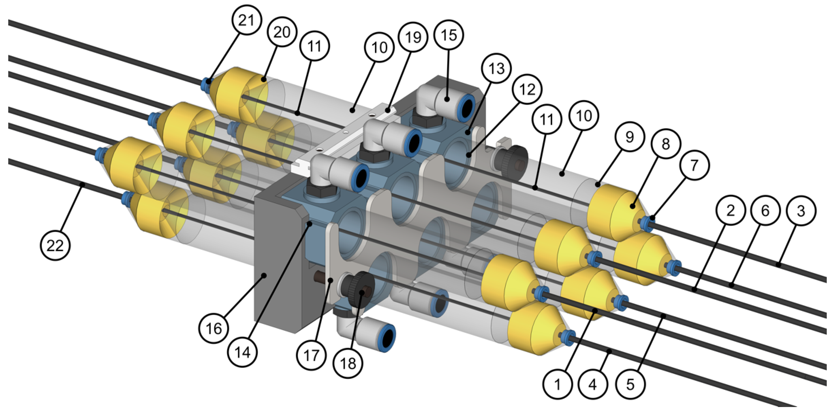
A novel impregnation unit was developed for the end-effector (Figure 4). To achieve sufficient impregnation, a single chamber per roving is used, and the outlets are minimal in diameter and have a ceramic rim.
The roving circularizes due to the high fiber tension and its passage through the circular eyelets. This decreases the surface-to-volume ratio and negatively impacts the impregnation quality. The ceramic eyelets set the maximum size of knots capable of passing through the system and prevent fiber shredding. Residual filament fragments can eventually accumulate in the resin chamber over time. To hold them back, resin-saturated hydro sponges (open-cell polyurethane foam) were introduced at the ends. They also seal the chamber and help with impregnation by pressing the roving flat.
The sponges are housed in two separate outer chambers to prevent any dislocation by high resin pressure or friction induced by the passing roving. The resin pressure is a result of the dynamic balance between the resin outflow (within fiber or leakage) and the inflow provided by the peristaltic pump controlled via feedback with the robot velocity. For a calibration liquid with a viscosity of 520 mPa s and a density of 1.002 g/cm3, which is close to the parameters of the resin used, the volume flow rate dV/dt in cm3/min and the pump setting R in rpm follow a linear equation with a coefficient of determination of 99.83%:
dV / d t = 0.779 cm 3   R

2.3.2. Fiber Tension Sensor Subsystem

After impregnation, all six rovings are combined at the assembly roller in the top front section. This metallic roller, placed in an exposed position, can be monitored, cleaned, and removed easily. It protects the ceramic sensor roller by absorbing disruptive fiber accumulations before they reach it.
The fibers apply a radial force on the sensor axis. Neglecting friction, the fiber tension can be calculated from this force by the addition of the two vectors of the adjacent fiber segments or by the wrapping angle at the sensor roller. For the selection of the measurement range of such a senor, the maximum fiber tension can be estimated in advance by using a spring scale in a series arrangement with the fiber during winding. The sensor is a commercially available textile single-roller radial force sensor containing a strain gauge measuring up to 40 N in one direction [37].
An amplifier inside the end-effector enables data forwarding to the computer system. This allows the measuring range to be tuned to the application by adjusting the offset and slope of a linear function between the measured force and output value. The offset should be set first. The aim is to map the relevant range of forces (0–max.) to be measured to the full range of the 16-bit integer values (0–65535) of sensor output.
The sensor is intended to work on textile machines with dry yarns, not with resin-impregnated carbon fibers in a dynamic environment. Therefore, a custom roller was needed, and the sensor was additionally protected by IP64 (Ingress Protection) sealing. A fiber passes through the system and is fixed above it, and then calibration is performed by hanging multiple known weights onto the fiber and mapping the sensor output values to them. This must be repeated whenever the fiber routing has changed. Direct calibration of the strain gauge is not recommended for this application. By adjusting the fiber routing, the same sensor can be reused in other force regimes.
Since the sensor must be installed orthogonally to the fiber strand, it protrudes laterally and therefore requires housing to protect it from collisions (Figure 3 (11)). The sensor is installed as close as possible to the TCP so that the collected data are dampened by friction as little as technically possible.

2.4. Material System for Large-Scale Fabrication

A material system of an object is an abstract description that includes the used raw materials, the applied processing method, their interaction, and their intended functions. It also extends to interactions with all conceptualized potential environments over time. It does not include the specific shape or geometry of an object but is limited to the form-defining characteristics that are inherited by the fabrication process. The parameters of the used material system are listed in Table 1.
The use of a 24K 1600tex version of the carbon fiber [39] was also considered to gain the advantage of faster impregnation and more even fiber deposition, but this would have doubled the fabrication time. For both carbon fibers and glass fibers [40], six rovings were added simultaneously. The used matrix system, the PTP resin, is a thermoset aliphatic epoxy resin based on renewable raw materials. PTP stands for prepolymer made of triglycerides and polycarboxylic acids [41]. In contrast to the epoxy resin used in previous projects [38], this resin has ecological advantages and a theoretically unlimited pot life. The latter is decisive for a production process that spans several days and in which freshly placed fibers must still to be able to deform and connect to those already in place. The resin and hardener react so slowly that both can be ordered premixed, and only the accelerator (4 wt %) has to be added prior to winding. A low starting viscosity, a consistent viscosity increase over time, and a low exothermic reaction are also beneficial for large-scale production. Even 25 kg can be mixed at the same time, which reduces the number of refill interruptions during winding.

3. Results

3.1. Validation of the Upscaled Process

To demonstrate the functionality of the developed setup and end-effector with the adjusted RCFW process, a component with a length of 9.2 m was produced, which is called the Big Fiber Component (BFC). The BFC is an upscaled version of a state-of-the-art building system with a 4 m length [38] (Figure 5).
During the fabrication of the BFC, more than 1600 m glass fibers and more than 500 m carbon fibers were processed in multiple winding sessions. Between sessions, the mixed PTP resin was stored in a freezer at −20 °C and thawed in a warm water bath (<100 °C) to continue winding even after several days. Defrosting progressed remarkably quickly. The energy needed to heat the resin from −20 to +20 °C was measured by differential scanning calorimetry (DSC) and determined to be −66.9 J/g. It was possible to substitute the active mixing step with a passive defrosting step, which led to a shorter preparation time. The DSC confirmed that the resin remained undamaged, showing an exothermic peak at 147.3 °C.
The total uninterrupted winding duration is equal to five hours. First, a carbon sine–cosine rim was wound on each frame perimeter, and then a form-defining glass body was wound, which was subsequently deformed by the carbon fiber reinforcement, which was placed at a steeper angle [7]. Finally, corner reinforcements were wound from carbon, and the resin was cured by an oven that was custom-built around the BFC. As a result, it was demonstrated that a cocoon-type oven can reach the necessary 120 °C over several hours for components with dimensions that exceed the sizes of conventional ovens.

3.2. Impregnation Quality Evaluation

The fiber volume ratio is an important parameter for fiber-reinforced composites since the effective fiber cross-section has to be considered in the design, not just the material bundle cross-section. For mechanical simulations, the material parameters were calibrated by performing full-scale tests with multiple loading scenarios.
The impregnation quality of the developed impregnation unit was measured on samples extracted from the BFC (Table 2). Measurements were taken according to DIN 16459:2019-12 by thermogravimetric analysis under a nitrogen atmosphere with a correction factor to compensate for remnants of the pure resin. Deviating from the DIN, the fiber mass ratio was calculated directly and then converted into the FVR using the densities of the resin and fibers since, in many cases, the density of the composite cannot be measured for RCFW objects or samples.
The deviation between the carbon fiber corner and reinforcement syntax in the middle of the BFC can be explained by the more compact fiber geometry of the corner syntax, resulting in a lower FVR. Higher TCP velocities while traveling between winding frames resulted in less impregnation and thus higher FVR. The differences from the FVR of glass syntaxes are a result of material characteristics, impregnation equipment, syntax, TCP trajectory, tool orientation, and winding speed.
Some applications target a higher FVR. However, for CFW, a value of 50% is more characteristic, since this helps to glue the separate fiber bundles together in the additive manufacturing process. A better bond can be achieved because the resin fills otherwise empty cavities between fibers on a macroscale. A lower FVR also more effectively counteracts buckling, which is particularly relevant for this specific building system. The strong variation in the FVR must be taken into account in a structural analysis. The low FVR of glass fibers is not a concern, as they are not involved structurally.

3.3. Analysis of Fiber Tension Sensor Data

Each free-spanning fiber has a sag, which can be reduced by increasing the fiber tension or decreasing the clamping distance or linear density of the fiber. As the size of the component (clamping distance) increases, the sag increases. In a passive setup, the friction applied to the fiber by the manufacturing system is the only parameter to compensate for the pulling force. If the pulling force exceeds the accumulated friction, the fibers are pulled through the system. Therefore, larger components require higher fiber tension levels. The main contributor to the friction is the impregnation unit. Additional tension can be provided by the creel and the spool holder brakes. When the TCP travels toward the last hooked winding pin, the tension drops; thus, the creel has to absorb fibers to maintain the tension. A drop in tension to zero must be prevented, since this means that the position of the fiber can no longer be accurately determined.
The tension sensor of the end-effector captures the fiber tension (Figure 6). The robotic monitoring system captures the TCP velocity and the pump rpm setting. All three parameters are recorded at 2 Hz throughout the whole fabrication process (Supplementary Material).
Figure 6 depicts a characteristic sample of one dataset (Figure S1c) of the measured fiber tension in newton for the initial body-shaping part of the underlying glass fiber body of the BFC. The syntax needs to be tracked to synchronize the used material and setup configuration with the gathered data (Figures S1 and S2). The syntax defines the geometrical interaction between the end-effector and winding frame, which is recognizable in the tension data.
In the data post-processing step, a Savitzky–Golay filter [42] was applied to smooth the signal (Figure 6 (black)) without affecting its characteristics. Using a cubic polynomial and a window width covering, half the hooking sequence duration delivered the best results. Additionally, automated hooking recognition was implemented for segmenting the signal (Figure 6 (orange)). As a result of that, the average period between hooking could be identified and equidistantly overlapped with the signal. In some datasets, a small deviation in the duration between two hooking events was found to accumulate over time (compare orange and blue marks in Figure 6).
Based on the hooking recognition (Figure 6 (orange)), the data segments had different lengths and had to be resampled. These segments were plotted onto each other for the whole dataset (Figure 7a), revealing the tension drop while hooking (motion at 100%) and the increase at the beginning of the free-spanning syntax (at ≈120%), which slowly decreases until the next rapid tension drop (at ≈80%), followed by the next hooking.
It is easily recognizable in Figure 6 that the fiber tension graph is more self-similar every second segment. Figure 7b reveals this improved fitting trend. The tension rises and falls at the plateaus of higher tension. This occurs during traveling phases. Further, the hooking at 100% (left side of the setup, Figure 2 (5)) is performed with lower tension than the hooking on the other side. In this case, the deviation between the hooking recognition (Figure 6 (orange)) and its average period (Figure 6 (blue)) disappears. These phenomena result from the mechanical differences of the one-axis positioners, as well as the asymmetry of the whole robotic setup and the TCP trajectory. Thus, for quality control, the signal was automatically cut at every second hooking.
Applying the same evaluation to the TCP velocity and the resin volume flow, the characteristic time-dependent values were extracted (Figure 7c,d). For the TCP velocity, a more rectangular pattern can be identified compared to the fiber tension (Figure 7b). For the manufacturing of a demonstrator component, average TCP traveling velocities of 175 mm/s and hooking velocities of 75 mm/s were achieved. A difference between traveling from left to right (100–150%) and vice versa (50–100%) can be identified. These differences are a result of the computer-generated TCP trajectory. The plateaus during traveling have different lengths. Accelerations and decelerations that occur during hooking also differ. This contributes to the asymmetry in the tension data. The tension positively correlates with the TCP velocity.
For the pump, some datasets show that the feedback loops worked as intended (Figure 7d). The resin volume flow decreases while hooking is performed due to the lower TCP velocity. The aim is to maintain the resin flow at a value equal to the resin consumption, which is set by the TCP velocity and the leakage of the impregnation chambers.
The presented sequence of the monitored parameters is characteristic of a syntax that switches sides after each hooking. These are the underlying glass syntaxes and carbon reinforcement syntaxes. Here, an overall increase in tension due to a switch from glass to carbon fibers can be recognized.
The corner syntax forms the final reinforcement on each side of the component. Here, multiple hooking events quickly occur in sequence; the tension at hooking drops more steeply, and tension while traveling is higher compared to the reinforcement syntax pattern. The reason for this is the limitation of the tension control system in absorbing fibers when distinctive traveling phases are missing. During the corner syntax, a higher demand for absorbing fibers is caused by the inevitable back traveling of the TCP. There is no consistent factor between the lower and higher levels of tension. However, the tension deviations are still in an acceptable range for RCFW.
Since the measured tension values and their averaged distribution have a unique position in space, which is the TCP position in the world coordinate system, this can be used to plot the dataset in a geometric relation (Figure 8). This provides an intuitive understanding of the data, can help to identify patterns as well as points of interest, and can be further developed into a tool that can demonstrate the fiber tension to the operator in real time. Intermediate segments can be identified as the TCP reorients in the orange–yellow areas of the graph.

4. Discussion and Conclusions

Several aspects of RCFW were improved to strengthen its applicability and relevance to the building industry and academia. The demonstrated levels of robot integrated textile equipment, end-effector integrated impregnation, and sensor-based process monitoring have never been achieved in construction-adapted RCFW fabrication methods. The presented research was successful in upscaling state-of-the-art fabrication limits by introducing a new material system, fabrication setup, and end-effector and implementing process adjustments. The end-effector is a modular multi-purpose research platform that is easy to maintain and handle. The tension control system, integrated in the end-effector, was not used during fabrication since the tension control system of the creel was more effective and the differences in tension between rovings were negligible. The resin allowed the duration of winding sessions to be extended to achieve the upscaling of the component. The freezing of premixed resin decreased the duration of the preparation phase. As a consequence of the digital coupling of the positioners instead of a mechanical coupling [17], the composite component could not be moved into a conventional oven after winding. With a custom-built oven, a new method of curing large-scale components within the setup was successfully demonstrated. The compactness of the setup allows on-site production in confined areas, such as shipping containers.
The developed textile equipment is physically and digitally integrated into the manufacturing system. This allows the relevant process parameters (fiber tension, TCP velocity, resin volume flow, and winding syntax) to be monitored for quality control and post-processing. Real-time monitoring can reveal nonconformities in the setup and can be used for quality control in serial production. Malfunctions and process disturbances can be immediately identified and resolved before they negatively affect the quality of the wound composite. The robotic system can react during the process due to real-time feedback loops and thus provide more uniform fiber deposition. The measured fiber tension regulates the TCP velocity, which adjusts the resin volume flow. The pre-stress of fibers in the component after curing does not fully correspond to the monitored fiber tension during winding. The acquisition of pre-stress would only be possible by integrating sensors into the composite.
The developed impregnation unit handles fast-varying fiber speeds, reduces the overall resin leakage compared to the state-of-the-art, and enables the direct control of the FVR by adjusting the resin volume flow while providing sufficient impregnation of the fiber bundle core. The unit allows significant fiber retraction and does not restrict the orientation of the winding end-effector. The sponges do not seal perfectly but remain operational throughout a complete winding session of a working day. The usage of separated impregnation chambers allows redundancy if one roving is damaged. It also allows flexibility in choosing the number of rovings according to engineering or aesthetic needs. A cleaner process is safer, more efficient and more applicable to serial production.
An accurate dataset that describes the process and its product proves to be an invaluable tool for a more comprehensive digital twin for CFW. This deeper understanding of the tension-related aspects of CFW has the potential to improve the design as well as simulation tools in the future and will contribute to a simulation methodology that is informed by the physical fabrication parameters of the fabricated component.

Supplementary Materials

The following are available online at https://www.mdpi.com/article/10.3390/pr9050806/s1, Figure S1: Monitoring datasets of the glass fiber syntaxes, Figure S2: Monitoring datasets of the carbon fiber syntaxes.

Author Contributions

Conceptualization, P.M. and S.B.; methodology, P.M.; software, P.M. and S.B.; validation, A.M. and G.T.G.; formal analysis, P.M.; investigation, P.M. and S.B.; resources, A.M. and G.T.G.; data curation, S.B.; writing—original draft preparation, P.M.; writing—review and editing, S.B.; visualization, P.M. and S.B.; supervision, A.M. and G.T.G.; project administration, A.M.; funding acquisition, A.M. All authors have read and agreed to the published version of the manuscript.

Funding

This research was funded by Baden-Württemberg Stiftung (Baden-Wuerttemberg Foundation) and partially supported by the Deutsche Forschungsgemeinschaft (DFG, German Research Foundation) under Germany’s Excellence Strategy-EXC 2120/1-390831618.

Data Availability Statement

Data is contained within the Supplementary Materials.

Acknowledgments

The authors would like to express their gratitude towards their fellow researchers Niccolò Dambrosio, Bas Rongen, Drilon Gubetini and Jan Knippers. Additionally, we thank Mark Steinmann for providing the DSC measurements, Klaus Dippon for providing the PTP resin, Zied Bhiri for his technical support with the robotic system and Venkata Rajasekhara Reddy Bade, August Lehrecke as well as Parisa Shafiee for the assistance during the research project.

Conflicts of Interest

The authors declare no conflict of interest. The funders had no role in the design of the study; in the collection, analyses, or interpretation of data; in the writing of the manuscript, or in the decision to publish the results.

References

  1. Liu, Y.; Zwingmann, B.; Schlaich, M. Carbon fiber reinforced polymer for cable structures: A review. Polymers 2015, 7, 2078–2099. [Google Scholar] [CrossRef] [Green Version]
  2. Schürmann, H. Konstruieren mit Faser-Kunstoff-Verbund, 2nd ed.; Springer: Berlin Heidelberg, Germany, 2007; pp. 11–17. [Google Scholar]
  3. Gil Pérez, M.; Rongen, B.; Koslowski, V.; Knippers, J. Structural design, optimization and detailing of the BUGA fibre pavilion. Int. J. Space Struct. 2020, 35, 147–159. [Google Scholar]
  4. Xing, J.; Geng, P.; Yang, T. Stress and deformation of multiple winding angle hybrid filament-wound thick cylinder under axial loading and internal and external pressure. Compos. Struct. 2015, 131, 868–877. [Google Scholar] [CrossRef]
  5. Wang, P.H.; Sterkenburg, R.; Kim, G.; He, Y. Investigating the void content, fiber content, and fiber orientation of 3d printed recycled carbon fiber. Key Eng. Mater. 2019, 801, 276–281. [Google Scholar]
  6. Mertiny, P.; Ellyin, F. Influence of the filament winding tension on physical and mechanical properties of reinforced composites. Compos. Part – Appl. S. 2002, 33, 1615–1622. [Google Scholar] [CrossRef]
  7. Zechmeister, C.; Bodea, S.; Dambrosio, N.; Menges, A. Design for Long-Span Core-Less Wound, Structural Composite Building Elements. In DMSB 2019—Impact: Design with All Senses, 1st ed.; Gengnagel, C., Baverel, O., Burry, J., Ramsgaard Thomsen, M., Weinzierl, S., Eds.; Springer: Cham, Switzerland, 2020; pp. 401–415. [Google Scholar]
  8. Sorrentino, L.; Anamateros, E.; Bellini, C.; Carrino, L.; Corcione, G.; Leone, A.; Paris, G. Robotic filament winding: An innovative technology to manufacture complex shape structural parts. Compos. Struct. 2019, 220, 699–707. [Google Scholar] [CrossRef]
  9. Zu, L.; Xu, H.; Wang, H.; Zhang, B.; Zi, B. Design and analysis of filament-wound composite pressure vessels based on non-geodesic winding. Compos. Struct. 2019, 207, 41–52. [Google Scholar] [CrossRef]
  10. Schulz, M.; Janssen, H.; Brecher, C. A digital shadow for the infrared-based tape laying process of tailored blanks out of thermoplastic unidirectional tape. Proc. CIRP 2019, 85, 224–229. [Google Scholar] [CrossRef]
  11. Clancy, G.; Peeters, D.; O’Higgins, R.M.; Weaver, P.M. In-line variable spreading of carbon fibre/thermoplastic pre-preg tapes for application in automatic tape placement. Mater. Design 2020, 194, 108967. [Google Scholar] [CrossRef]
  12. Dutra, T.A.; Ferreira, R.T.L.; Resende, H.B.; Guimarães, A. Mechanical characterization and asymptotic homogenization of 3D-printed continuous carbon fiber-reinforced thermoplastic. J. Braz. Soc. Mech. Sci. Eng. 2019, 41, 133. [Google Scholar] [CrossRef]
  13. Fijul Kabir, S.M.; Mathur, K.; Seyam, A.-F.M. A critical review on 3D printed continuous fiber-reinforced composites: History, mechanism, materials and properties. Compos. Struct. 2020, 232, 111476. [Google Scholar] [CrossRef]
  14. Tyler, K.L. Method and Apparatus for Continuous Composite Three-Dimensional Printing. U.S. Patent 10,744,707, 18 August 2020. [Google Scholar]
  15. Büchler, D.; Elsken, T.; Glück, N.; Sier, M.; Bludszuweit, S. Ultraleichte Raumzelle—Entwicklung von ultraleichten Großstrukturen in Faserverbund- und Hybridbauweise für den Schiffbau. In Statustagung Schifffahrt und Meerestechnik, 1st ed.; Forschungszentrum: Jülich, Germany, 2011; pp. 25–45. [Google Scholar]
  16. Prado, M.; Dörstelmann, M.; Menges, A.; Solly, J.; Knippers, J. Elytra Filament Pavilion: Robotic Filament Winding for Structural Composite Building Systems. In Fabricate 2017; Menges, A., Sheil, B., Glynn, R., Skavara, M., Eds.; UCL Press: London, UK, 2017; pp. 224–231. [Google Scholar]
  17. Bodea, S.; Zechmeister, C.; Dambrosio, N.; Dörstelmann, M.; Menges, A. Robotic coreless filament winding for hyperboloid tubular composite components in construction. Automat. Constr. 2021, 126, 103649. [Google Scholar] [CrossRef]
  18. Minsch, N.; Müller, M.; Gereke, T.; Nocke, A.; Cherif, C. 3D truss structures with coreless 3D filament winding technology. J. Compos. Mater. 2019, 53, 2077–2089. [Google Scholar] [CrossRef]
  19. Menges, A.; Knippers, J.; Wagner, H.J.; Zechmeister, C. Pilotprojekte für ein Integratives Computerbasiertes Planen und Bauen. In Baustatik—Baupraxis 14; Bischoff, M., von Scheven, M., Oesterle, B., Eds.; University of Stuttgart: Stuttgart, Germany, 2020; pp. 67–79. [Google Scholar]
  20. Reichert, S.; Schwinn, T.; La Magna, R.; Waimer, F.; Knippers, J.; Menges, A. Fibrous structures: An integrative approach to design computation, simulation and fabrication for lightweight, glass and carbon fibre composite structures in architecture based on biomimetic design principles. Comput. Aided Design 2014, 52, 27–39. [Google Scholar] [CrossRef]
  21. Imamura, T.; Kuroiwa, T.; Terashima, K.; Takemoto, H. Design and tension control of filament winding system. In Proceedings of the 1999 IEEE International Conference on Systems, Man, and Cybernetics, Tokyo, Japan, 12–15 October 1999; IEEE: New York, NY, USA, 1999; pp. 660–670. [Google Scholar]
  22. Yeung, M.F.; Falkner, A.H.; Gergely, S. The control of tension in textile filament winding. Mechatronics 1995, 5, 117–131. [Google Scholar] [CrossRef]
  23. Gloy, Y.; Beck, T.; Hehl, A.; Niebel, V.; Wischnowski, M.; Schulte Südhoff, E.; Raina, M.; Gries, T. Sensoren für Bioprozess- und Verfahrenstechnik. In Proceedings of the 11. Dresdner Sensor-Symposium, Dresden, Germany, 9–11 December 2013; AMA: Berlin, Germany, 2013; pp. 445–449. [Google Scholar]
  24. Mohamed, A.; Rana, A.; Motaz, A. Yarn tension control technique for improving polyester soft winding process. Sci. Rep. 2021, 11, 1060. [Google Scholar]
  25. La Magna, R.; Waimer, F.; Knippers, J. Coreless Winding and Assembled Core – Novel fabrication approaches for FRP based components in building construction. Constr. Build. Mater. 2016, 127, 1009–1016. [Google Scholar] [CrossRef]
  26. Bodea, S.; Dambrosio, N.; Zechmeister, C.; Gil Pérez, M.; Koslowski, V.; Rongen, B.; Dörstelmann, M.; Knippers, J.; Menges, A.; Kyjanek, O. BUGA Fibre Pavilion: Towards robotically-fabricated composite building structures. In Fabricate 2020; Burry, J., Sabin, J.E., Sheil, B., Skavara, M., Eds.; UCL Press: London, UK, 2020; pp. 234–243. [Google Scholar]
  27. Prado, P. Skeletal composites: Robotic fabrication processes for lightweight multi-nodal structural components. Constr. Robot. 2020, 4, 217–226. [Google Scholar] [CrossRef]
  28. Pan, N. Theoretical determination of the optimal fiber volume fraction and fiber-matrix property compatibility of short fiber composites. Polym. Compos. 1993, 14, 85–93. [Google Scholar] [CrossRef] [Green Version]
  29. Mindermann, P.; Gresser, G.T. Robotic 3D Deposition of Impregnated Carbon Rovings with Gradient Properties for Primary Structures. In Proceedings of the 69th International Astronautical Congress, Bremen, Germany, 1–5 October 2015; IAF: Paris, France, 2018. [Google Scholar]
  30. Rongen, B.; Koslowski, V.; Gil Pérez, M.; Knippers, J. Structural optimization and rationalization of the BUGA fibre composite dome. In Proceedings of the IASS Annual Symposium 2019—Structural Membranes, Barcelona, Spain, 7–10 October 2019; Lázaro, C., Bletzinger, K.-U., Oñate, E., Eds.; IASS: Madrid, Spain, 2019. [Google Scholar]
  31. Chang, C.; Han, Z.; Li, X.; Sun, S.; Qin, J.; Fu, H. A non-geodesic trajectory design method and its post-processing for robotic filament winding of composite tee pipes. Materials 2021, 14, 847. [Google Scholar] [CrossRef]
  32. Kuka KR 420 R3080—Technical Data Sheet. Available online: https://www.kuka.com/-/media/kuka-downloads/imported/6b77eecacfe542d3b736af377562ecaa/0000233239_en.pdf?rev=c80332ccaa9a4dcda3433ed8197bcd82&hash=606C12B8C4483F37AE4A8B70BD7147C6 (accessed on 17 April 2021).
  33. Kuka Industrial Robotics-Linear Units and Positioners—Technical Data Sheet. Available online: https://www.kuka.com/-/media/kuka-downloads/imported/9cb8e311bfd744b4b0eab25ca883f6d3/kuka_pb_positioners_linear_units_en.pdf?rev=5b41e95fde78472a8c152eb8f4b1c4e6 (accessed on 17 April 2021).
  34. Rhinoceros. Available online: https://www.rhino3d.com (accessed on 26 April 2021).
  35. Grasshopper. Available online: https://www.grasshopper3d.com (accessed on 26 April 2021).
  36. KUKA Application and Robot Programming—KRL (KUKA Robot Language). Available online: https://www.kuka.com/en-de/services/engineering/application-and-robot-programming (accessed on 26 April 2021).
  37. Radialkraft-Messwertaufnehmer der Baureihen M 1391 und M 1392—Technical Data Sheet. Available online: https://tensometric.de/pdf/daten/deutsch/1-rollen-systeme/M1391-92-D.pdf (accessed on 17 April 2021).
  38. Dambrosio, N.; Zechmeister, C.; Bodea, S.; Koslowski, V.; Gil Pérez, M.; Rongen, B.; Knippers, J.; Menges, A. Towards an architectural application of novel fiber composite building systems—The BUGA Fibre Pavilion. In Ubiquity and Autonomy, Proceedings of the 39th Annual Conference of the Association for Computer Aided Design in Architecture, Austin, TX, USA, 24–26 October 2019; ACADIA: Fargo, ND, USA, 2019; pp. 140–149. [Google Scholar]
  39. Teijin Tenax Filament Yarn—Product Data Sheet. Available online: https://www.teijincarbon.com/fileadmin/PDF/Datenblätter_en/Product_Data_Sheet_TSG01en__EU_Filament_.pdf (accessed on 17 April 2021).
  40. Owens Corning Pipestrand S2300 Single-End Roving—Product Information. Available online: https://www.owenscorning.com/en-us/composites/product/pipestrand-roving-s2300-and-s2500 (accessed on 17 April 2021).
  41. Bio-Composites and More GmbH - PTP-Resins—Product Information. Available online: https://bio-composites.eu/en/ptp-resins/ (accessed on 17 April 2021).
  42. Luo, J.; Ying, K.; Bai, J. Savitzky–Golay smoothing and differentiation filter for even number data. Signal Process. 2005, 85, 1429–1434. [Google Scholar] [CrossRef]
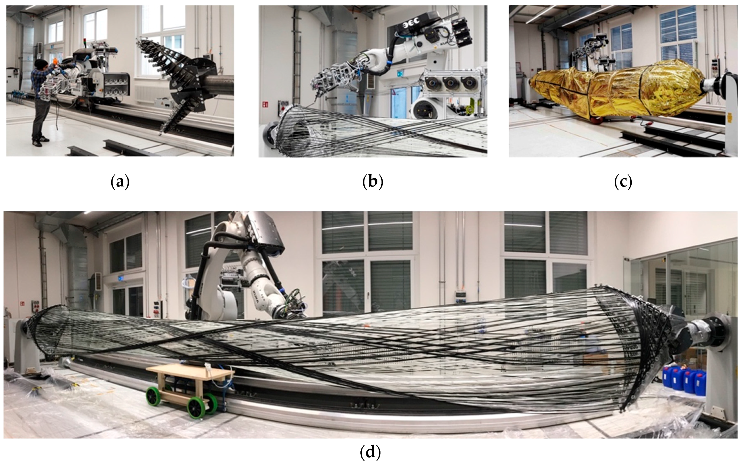
Figure 1. RCFW process and setup overview. (a) Winding equipment preparation phase; (b) carbon fiber winding sessions; (c) curing the resin in a custom-built oven; (d) the component after winding.
Processes 09 00806 g001
Figure 2. CAD of the large-scale cyber-physical winding setup. 1: industrial robot (6-axis); 2: 10 m linear track (7: external axis); 3: left one-axis positioner (8: external axis); 4: right one-axis positioner (9: external axis); 5: left winding frame; 6: right winding frame; 7: large-scale C/GFRP lattice structural component (Big Fiber Component); 8: floor recessed harbor rail; 9: H-shaped steel beam; 10: robot switch cabinets; 11: pump switch cabinet including mobile control device; 12: cable tow; 13: robot-attached storage trolley; 14: glass fiber spools; 15: resin container; 16: resin supply tubes; 17: peristaltic pump; 18: fiber guiding elements; 19: outer three carbon fiber spools, additional three behind it; 20: spool holder incl. mechanical brake; 21: passive tension control system; 22: robot-mounted aluminum profile frame; 23: traveling dry fiber bundles; 24: winding end-effector; 25: tool center point; 26: sensor switch cabinet.
Processes 09 00806 g002
Figure 3. Robotic winding end-effector (Figure 2 (24)). (a) CAD, 1: robot; 2: supply hose; 3: sensor cable; 4: amplifier; 5: resin supply tubes; 6: adapter plate; 7: aluminum profile structure; 8: stiffening plates; 9: steel cable bracings; 10: joint of the TCP section; 11: sensor housing; 12: internal tensioning system; 13: six incoming dry rovings; 14: ceramic fiber guiding funnels; 15: fiber catching system; 16: spring damped joint; 17: impregnation unit; 18: steel fiber guiding rings; 19: assembly roller; 20: sensor roller; 21: tension sensor; 22: exposed tube; 23: nozzle; 24: tool center point (TCP); 25: fiber fixing bolts; 26: impregnated fiber strand. (b) Photo during fabrication of a carbon fiber syntax.
Processes 09 00806 g003
Figure 4. Impregnation unit (Figure 3 (17)). Axonometric projection (resin not shown) with fibers traveling from right to left. 1–6: dry circular rovings on position 1 to 6; 7: ceramic eyelet; 8: horizontally cut sponge; 9: rear sponge chamber; 10: impregnation cartridge; 11: wet planar roving in impregnation chamber; 12: silicon tape sealed threaded connection; 13: 3D-printed cartridge holder; 14: self-alignment wedge; 15: resin supply tube connector; 16: 3D-printed chamber holder; 17: carbon fiber reinforced 3D-printed clamping plate; 18: knurled nut; 19: slider for attachment to the aluminum profile (1 of 2); 20: front sponge chamber; 21: inverted ceramic eyelet; 22: impregnated circular roving.
Processes 09 00806 g004
Figure 5. Fabricated research demonstrators. Big Fiber Component (top) and a BUGA-type state-of-the-art component (bottom).
Processes 09 00806 g005
Figure 6. Measured fiber tension data sample. Savitzky–Golay filtered (black) fiber tension (gray) measured over time with automated peak recognition (orange), average period (blue), and arithmetic mean value (green).
Processes 09 00806 g006
Figure 7. Fiber tension analysis. (a) Overlapped fiber tension between each hooking, average (black) and original data (gray), with hooking at 100% with an average duration of 58 s; (b) overlapped fiber tension each second of hooking, with hooking at 50%, 100%, and 150%; (c) TCP velocity, average (blue) and original data (light blue), with hooking at 50%, 100% and 150%; (d) resin volume flow, average (green) and original data (light green); the calculated values are based on the recorded pump rpm setting, with hooking at 50%, 100%, and 150%.
Processes 09 00806 g007
Figure 8. Average fiber tension mapped onto the TCP trajectory. The dataset of Figure 7b was used, and the linear scale is between 44.4 N (red) and 169.2 N (blue).
Processes 09 00806 g008
Table 1. Overview of the used material system.
Used Raw
Material
Processing
Method
Internal
Interaction
Intended
Function
Environmental
Interaction
Form-Defining
Characteristics
Teijin Tenax-E STS40 F13 48K 3200texrobotic coreless filament winding
and thermal curing
mutual
displacement
due to tension
and friction,
becoming a
composite
reinforcement of the componentinsignificantlattice fiber
composite
structure
conforming to
the BUGA [38]
building system type
Owens Corning PipeStrand S2300 2400tex LS BP11 S CF Ashaping of the fiber body by pushing carbon fiber outwardsinsignificant
B.A.M. PTP resinmatrix of the composite, adhesive joint to the sleevesaging due to
sun expose, etc.
zinc-plated steel,
1.0718
sleeves mounted by bolt connectionadhesive joint with C/GFRPwinding pins and force transmission sleevesinsignificant
Table 2. Overview of the fiber volume ratio measurements of the Big Fiber Component.
Sample LocationMaterialFVRSample Size
corner syntaxCFRP51.9 ± 2.0%8
free spanning syntaxCFRP59.7 ± 1.5%8
free spanning syntaxGFRP38.4 ± 3.0%12
Publisher’s Note: MDPI stays neutral with regard to jurisdictional claims in published maps and institutional affiliations.