Article

Effect of the Gas Volume Fraction on the Pressure Load of the Multiphase Pump Blade

1
Key Laboratory of Fluid and Power Machinery, Ministry of Education, Xihua University, Chengdu 610039, China
2
State Key Laboratory of Hydroscience and Engineering, Department of Energy and Power Engineering, Tsinghua University, Beijing 100084, China
*
Authors to whom correspondence should be addressed.
Processes 2021, 9(4), 650; https://doi.org/10.3390/pr9040650
Submission received: 19 March 2021 / Revised: 2 April 2021 / Accepted: 6 April 2021 / Published: 8 April 2021

Abstract

:
The gas volume fraction (GVF) often changes from time to time in a multiphase pump, causing the power capability of the pump to be increasingly affected. In the purpose of revealing the pressure load characteristics of the multiphase pump impeller blade with the gas-liquid two-phase case, firstly, a numerical simulation which uses the SST k-ω turbulence model is verified with an experiment. Then, the computational fluid dynamics (CFD) software is employed to investigate the variation characteristics of static pressure and pressure load of the multiphase pump impeller blade under the diverse inlet gas volume fractions (IGVFs) and flow rates. The results show that the effect of IGVF on the head and hydraulic efficiency at a small flow rate is obviously less than that at design and large flow rates. The static pressure on the blade pressure side (PS) is scarcely affected by the IGVF. However, the IGVF has an evident effect on the static pressure on the impeller blade suction side (SS). Moreover, the pump power capability is descended by degrees as the IGVF increases, and it is also descended with the increase of the flow rate at the impeller inlet. Simultaneously, under the same IGVF, with the increase of the flow rate, the peak value of the pressure load begins to gradually move toward the outlet and its value from hub to shroud is increased. The research results have important theoretical significance for improving the power capability of the multiphase pump impeller.

1. Introduction

Offshore oilfields have been flourishing and thriving these years due to the rich resources in the sea, such as the petroleum, natural gas and so on. To effectively transport the multiphase substances in the deep sea, the multiphase pump has emerged at the right moment, and has been gradually applied to the onshore oilfields. There are numerous advantages to using this pump, such as compact structure, large discharge and insensitivity toward the sand particles. Moreover, it still operates well under the high gas void fraction. Furthermore, the transportation approaches using multiphase pump reduce expenses on equipment and management investment, and raise the oil recovery rate, compared with traditional transportation technologies.
The impeller, as the core flow passage and power component, has a significant effect on the high-efficiency as well as stable operation of featured by the pump. Moreover, the internal flow and power capability characteristics of the multiphase pump are more complex compared with the single-phase pump, as it could operate within the gas-liquid two-phase case and the gas void fraction in the pump usually varies a lot. To further improve the power capability characteristics of multiphase pump, lots of researchers have aimed to solve this problem. Shi Y. et al. [1] investigated the flow characteristics featured by a three-stage helico-axial multiphase pump, and pointed out that the best efficiency point (BEP) with design parameters and water case is 45%. Meanwhile, the pump can prevent excessive degradation on hydraulic performance at the low IGVFs. Shi GT. et al. [2] employed the numerical simulation approaches to prob into the pressurization performance in different impeller regions under the different flow rates and IGVFs. Results demonstrated that the closer to the shroud, the stronger the pressurization performance at the front of blades was; however, at the latter half of blades, the shorter distance to the hub, the more strength of the pressurization performance would be. Zhang WW. et al. [3] analyzed the characteristics of internal flow and phase interaction in a gas-liquid two-phase pump, and proposed that the gas distribution in the inlet pipe was uniform and a stratified structure in the outlet pipe under air-water combination was formatted. Moreover, the variation trend of interphase forces along the flow direction under air-crude combinations in the impeller was relatively smooth. Zhang WW. et al. [4] investigated the flow field and gas-liquid phase interaction characteristics featured by a multiphase pump. The research expressed that as the IGVF increased, the variation range of interphase forces in the impeller was greater than that in the diffuser. Moreover, the gas in the impeller was mainly accumulated near the blade SS at the impeller outlet. Shi Y. et al [5] utilized steady numerical simulations to investigate the two-phase flow characteristics in normal impeller and split vane impeller at different IGVFs. The results presented that the performance featured by the modified impeller is generally better than the normal impeller, especially in high IGVF case. Li CH. et al. [6] uncovered the pressure fluctuation and internal-flow characteristics in a three-stage multiphase pump at different IGVFs. As was shown by the results, the improvement of the pump performance was under the restriction of the upgrade of the flow rate. In addition, the pressure fluctuation amplitude neighboring the impeller blade SS gradually increased. Jinsong Z. et al. [7] evaluated the effects of GVF on energy performance and pressure fluctuations of a multiphase pump by a numerical approach as well as a Navier-Stokes equation solution. As was shown in the results, the dominant frequencies of pressure fluctuation in the impeller and diffuser took on 11 and three times as much, respectively, as compared to those featured by the impeller rotational frequency individually. Cui B. et al. [8] investigated the transient pressure pulsation, unstable flow structure, and vibration displacement of a centrifugal pump with different cutting angles. According to the results, the heads and efficiency of the pumps with 30 deg and 45 deg cutting angles of the trailing edge have achieved improvement.
In terms of internal flow mechanism, Zhang W. et al. [9] researched the characteristics featured by bubble motion as well as distribution in multiphase pumps based on the basis of the Euler two-fluid model. As the experimental results presented, bubbles in the impeller started to move and then accumulated from the blade PS to the blade SS on an analogous path. Next, the accumulated bubbles were on the decrease in size the moment they hit the blade wall. Furthermore, the bubble diameter in the guide vane was significantly greater than that in the impeller. Yan S. et al. [10] tested the Euler-Euler in-homogeneous two-phase flow model together with a discrete particle population balance model (PBM), which targets the research on the bubble distribution in a multiphase pump of a three-stage gas-liquid two-phase centrifugal pump. Shi G. et al. [11] carried out research on the energy conversion characteristics featured by the impeller blades under water as well as the gas-liquid two-phase under design working case; the results showed that the capacity of impeller energy conversion would have a step-by-step increase the moment the blade wrap angle changed from 0 to 60 degrees, and the capability began to degenerate gradually when the wrap angle was larger compared with 60 degrees. Moreover, the energy conversion performance under the gas-liquid two-phase case was worse than that of water alone. Han et al. [12] investigated the thickness variation in the air foil based on the hub toward the shroud of the blade on the mixture transportation characteristics featured by the gas-liquid two-phase flow in a helical-axial pump, the results indicated that the head coefficient and efficiency increased for the same hub thickness, and the aggregation degree of gas decreased with the decreasing of the thickness ratio coefficient. Yue H. et al. [13] conducted an analysis on the energy performance as well as radial force of a multiphase pump based on symmetrical and unsymmetrical tip clearance. According to the results, the total radial force on the principal axis harbored close association to the fluctuation of mass flow rate within each single flow passage and the radial force upon the blade PS decreased as the tip clearance increased. Zhang J S. et al. [14] selected tip clearance sizes of 0.0, 0.2, 0.5, and 0.8 mm for investigating the effects of tip clearance oriented with energy performance and flow characteristics of a multiphase pump. As the results demonstrated, the dominant frequencies and maximum amplitudes of pressure fluctuation rose were rising along with the growth in tip clearance. Furthermore, the entrainment effect between the tip leakage flow and main flow in the impeller also strengthened with the increase in tip clearance size. Monte Verde W. et al. [15] studied the gas-liquid flow patterns in a centrifugal pump impeller through experiments. The observation indicated that the intensity of pump performance degradation were under direct influence of the flow pattern within the impeller. Xu Y. et al. [16] investigated sufficiently the multiphase performance as well as the inner flow. The results showed that the dominant frequency under water and water-air circumstances was the blade passing frequency, the pressure fluctuation was obviously weakened in the downstream of the impeller, and the fluctuation of pressure with water-air case greatly increased in comparison with water case.
In the optimization design of a multiphase pump, Ming L. et al. [17] suggested an updated approach aiming to create an optimize performance of multi-stage multiphase pump in virtue by theoretical prediction on the basis of an Oseen vortex; the pump head and efficiency could have an improvement at a rate of 0.29% and 0.19% on average following the application of the optimization approach. Liu M. et al. [18] also proposed a hydraulic design approach of a controllable blade angle oriented with a multiphase pump based on an impeller and diffuser; the results revealed that the distributions of GVF as well as the pressure would be of more uniformity following the optimization, thus enhancing transporting performance of the pump. Li C. et al. [19] carried out research on the outer features and inner flow identities of the multiphase pump amidst various GVF circumstances on the basis of the Euler-Euler heterogeneous flow model. The results offered showed that the head and efficiency presented obvious improvement when the reduction of the inner wall of the diversion cavity occurred to 4 mm to the radial direction. Jun-Won S. et al. [20] reported the multi-objective optimization to simultaneous enhancement in pressure and efficiency at the posterior stage; the results showed that selected optimal model could achieve more hydrodynamic performance compared to the base model. Cao S. et al. [21] presented an integrated method of inverse method as well as a direct flow analysis oriented with the hydrodynamic design of gas-liquid two-phase flow multiphase pump impeller. According to the results, the designed pump worked in a broad flow rate range until the IGVF could increase to over 50%. Hu H. et al. [22] used CFD and genetic algorithm to optimize the impellers of helicon-axial multiphase pump; the optimization result showed that the hydraulic efficiency of the multiphase pump is increased by 1.91%.
On the strength of the analyses above, lots of scholars have investigated the multiphase pump in many aspects, such as internal flow, pressure fluctuation and performance improvements, etc. Some remarkable results have been obtained. However, quantitative research on the power capability of an impeller blade is relatively rare. Thus, the characteristics of the static pressure, gas distribution, and pressure load in the multiphase pump are investigated in the present work through adjusting the IGVF and flow rate, which reveals the effect of IGVF and flow rate on power capability of the pump. The research results provide the references for the structure optimization design of the multiphase pump impeller blade, and it is also helpful to improve the work performance of the multiphase pump.

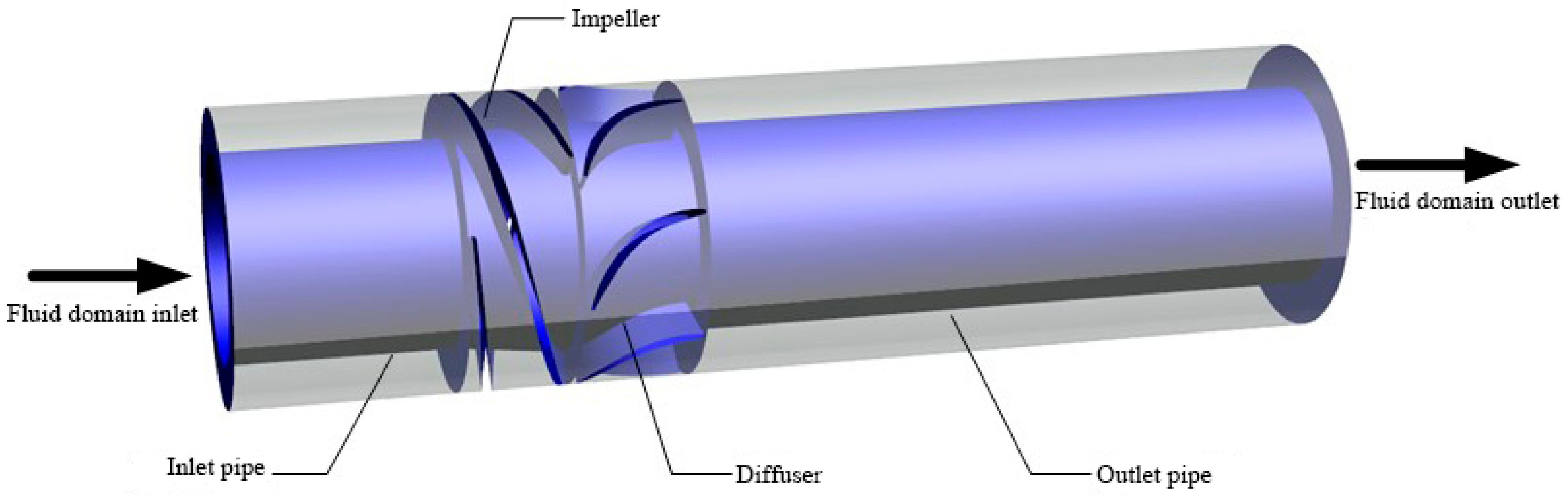
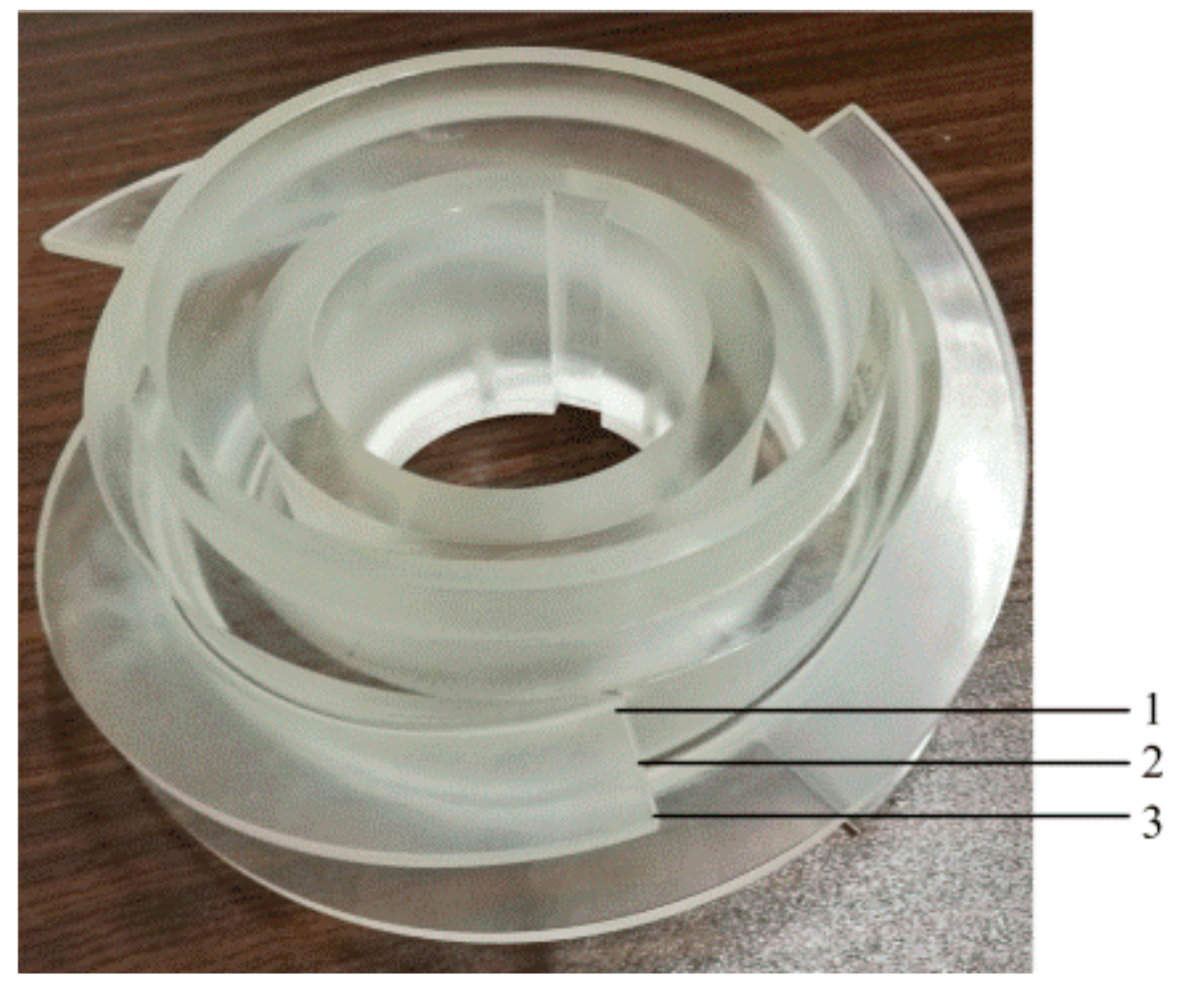
2. Multiphase Pump Computational Model

The six-stage self-design multiphase pump model is selected in this paper and its basic parameters are as follows. The design flow rate, head, and rotational speed are 100 m3/h, 85 m, and 3000 rpm, respectively. The blade numbers of the impeller and diffuser blade are 3 and 7, respectively. The pump efficiency is 33%, and GVF ranges from 0 to 80%. The impeller hub ratio is 0.60, the impeller cascade solidity is 1.2, the impeller blade average wrap angle is 181°, and the impeller average blade angle is 8.2°. The diffuser blade average wrap angle is 40°, and its diffusion angle is 8°. Taking the numerous numerical simulations and computer performance, a single pressurization unit of multiphase pump was adopted and investigated. The computational fluid domain of a single pressurization unit is composed of four parts, namely, the inlet pipe (inlet extension), impeller, diffuser, and outlet pipe (outlet extension). To guarantee the inlet and outlet flow developed more fully, the impeller inlet and diffuser outlet were prolonged 2 and 6 times of the impeller axial length, respectively. The BladeGen, which is professional modeling software for turbomachinery, is also a module of ANSYS Workbench. This article mainly uses it for the hydraulic design of the blade, and it is adopted to model the impeller and diffuser. The computational model and impeller spans are shown in Figure 1 and Figure 2.

3. Numerical Simulation Methods and Settings

3.1. Governing Equations

The k-ω two-equation turbulence model based on the SST (Shear Stress Transport) model is selected. The transportation of the turbulent shear stress is taken into consideration in this model and it preferably predicts the start of the flow and the flow separation with the adverse pressure gradient; hence, the simulation results are more reliable. The expressions of the k-ω SST model are as follows:
ρ k t + ρ u i k x i = x j ( u + u i σ k ) k x j + G k β ρ k ω
t ρ ω + x j ρ u j ω = x j μ + μ t σ ω ω x j + G ω ρ β ω 2 + D ω
where t is time, ρ is fluid density, and k is turbulent kinetic energy; ui and uj are the temporal mean velocity in i and j directions; xi and xj are the displacements in Cartesian coordinates in i and j directions; β is the thermal expansion coefficient and ω is the specific dissipation rate; μ is the dynamic viscosity of the fluid and μt is the turbulent viscosity; σk is the Prandtl number corresponding to the turbulent kinetic energy and Gk is the generation term of the turbulent kinetic energy caused by the average velocity gradient; and σω is the turbulent Prandtl number with the specific dissipation rate, Gω is the generation term of the specific dissipation rate, and Dω is the orthogonal divergence term.
To solve the excessive turbulence flow problems in local region with k-ω SST model, the new dissipation item is added to the turbulent dissipation rate, ω:
2 ρ ( 1 F 1 ) ω σ ω ( k ω x x + k ω y y + k ω z z )
where F1 denotes the wall distance.

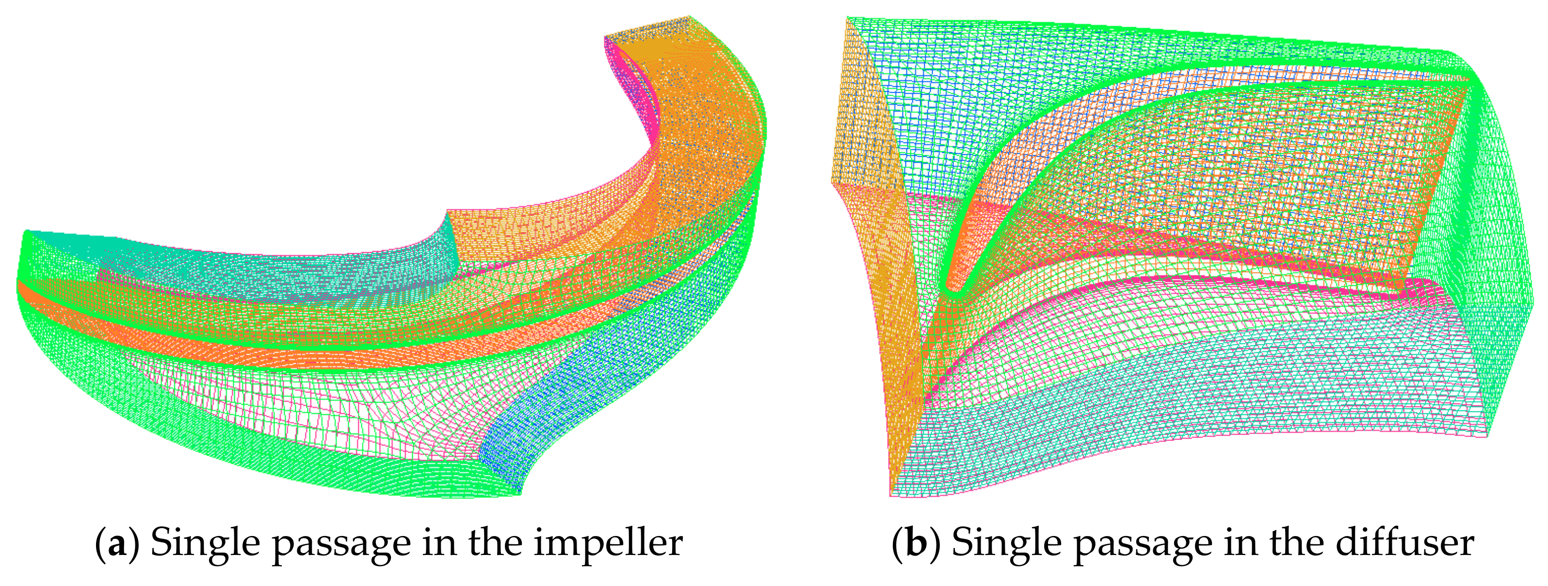
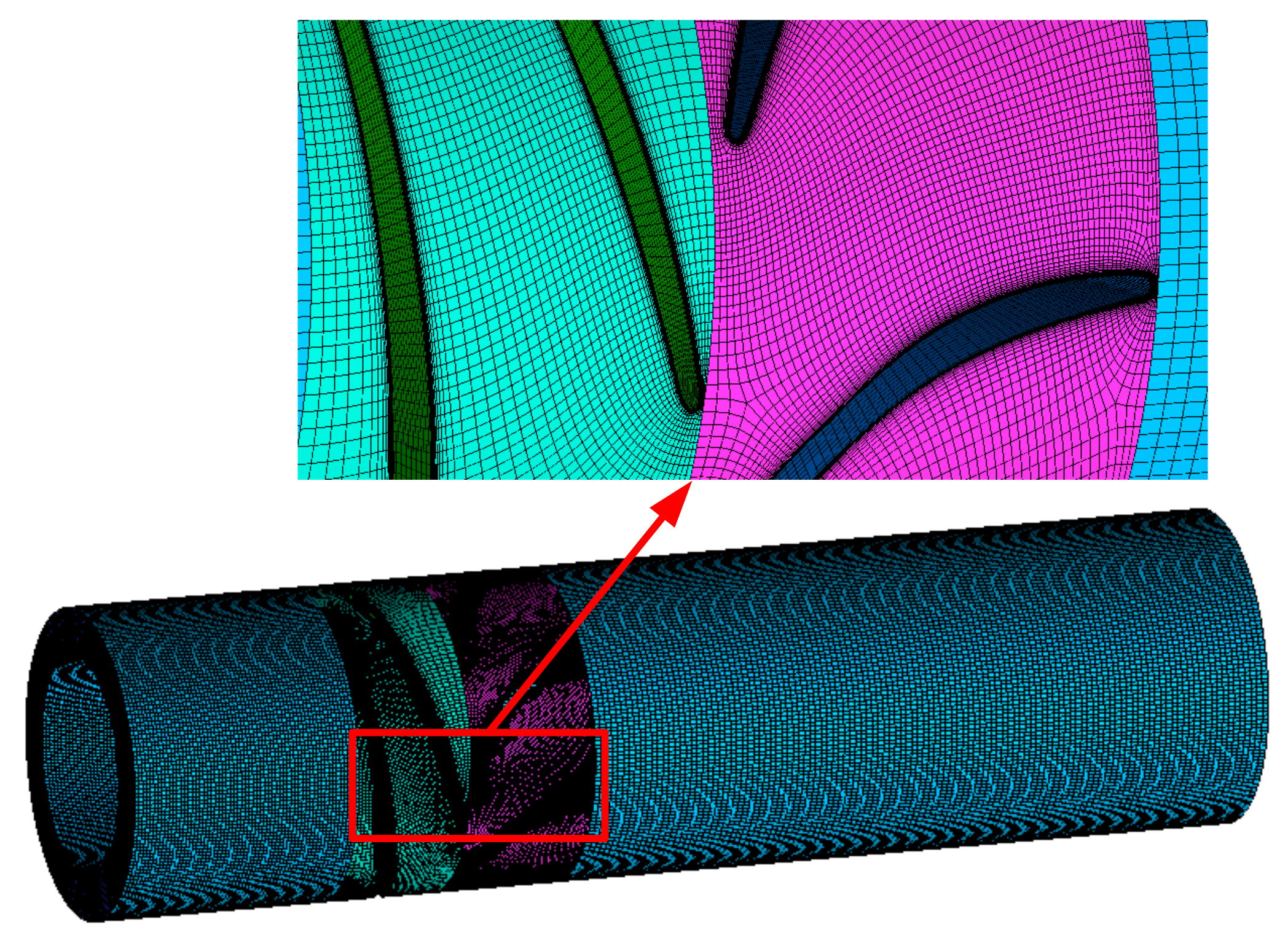
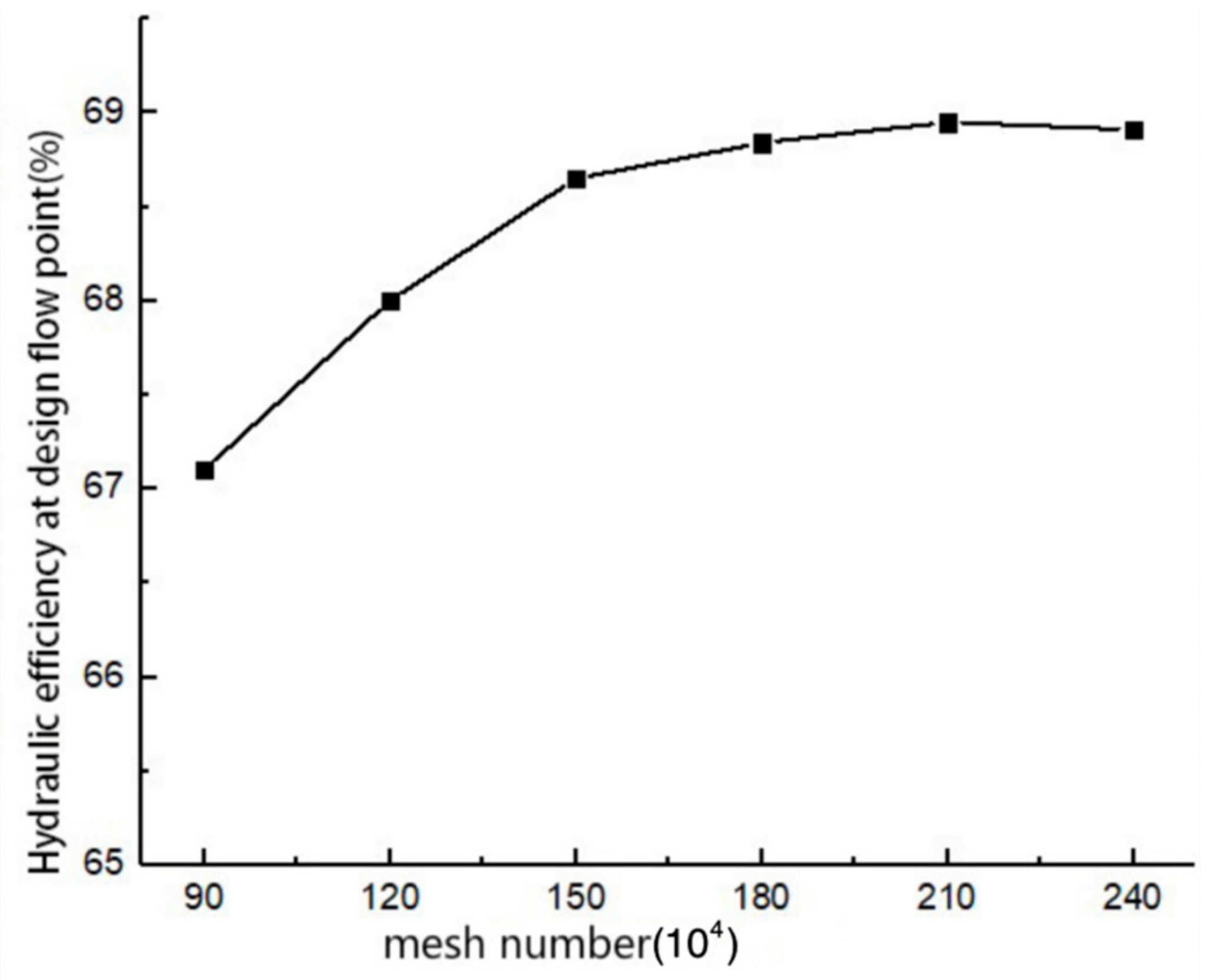
3.2. Mesh Arrangement and Independence Verification

The professional turbomachinery software TurboGrid is employed to generate the impeller and diffuser mesh, and the inlet and outlet extension of the computational domain is imported into ICEM for the hexahedral mesh. Moreover, ICEM is utilized to generate the inlet and outlet extension mesh. Figure 3 displays the single-passage structure mesh of the impeller and diffuser. The mesh that is near the wall is partially refined to capture the complicated flow in the boundary layer. The overall computational domain structure mesh is shown in Figure 4.
To ensure the accuracy of the calculation results, six sets of meshes are divided to verify the independence of the computational domain mesh under 100 m3/h. As can be seen in Figure 5, as the number of meshes increase, the hydraulic efficiency of the computational domain gradually stabilizes. When the number of meshes exceeds 2.1 million, the hydraulic efficiency remains almost unchanged, and the meshes also satisfy the y+ value requirement of the selected turbulence model. y+ is a dimensionless value, of which the equation is:
y + = y τ w ρ μ
where y is the distance between the first layer of mesh and the wall and τw represents the shear stress at the wall. In consideration of the calculation performance and accuracy of the computer, it is shown that when the total mesh number is 2.1 million, a better convergence solution will be obtained in the process of numerical calculation. Meanwhile, it is supposed that the y+ value near the wall of each part is kept within 30.

3.3. Boundary Case Settings

To calculate the inner flow of the multiphase pump, ANSYS software is employed. The k-ω SST turbulence model is chosen for liquid phase and the zero equation is selected for gas phase in the gas-liquid two-phase case. As shown in Table 1, The inlet boundary circumstances are converted into actual speeds under a variety of working circumstances according to the minimum flow, rated flow, and maximum flow under the actual work case of the multiphase pump. The inlet boundary was set as the normal velocity inlet and the outlet boundary case as the static pressure outlet. No slip boundary case is set for the wall, and the near wall domain selects the Scalable wall function. The impeller domain is set to a rotating coordinate system, and the rest of the parts are set to a static coordinate system. The Frozen Rotor model is used for rotor-stator interface, and stator interface uses General connection (direct connection); the convergence criterion is set to 10−5.

3.4. Numerical Method Verification

Figure 6 is the multiphase pump test system, composed of a multiphase pump, motor, gas-liquid mixing tank, lubrication system, cooling system, control system, water supply system, gas supply system, pipelines, and valves.
The flow field of high-speed photography and the numerical simulation flow field are compared and analyzed, and it is verified that the numerical calculation method is reliable. The results are shown in Figure 7. By comparison, the experimental blade tip flow field consists of the numerical calculation flow field, especially underwater working circumstances, which indicates that the numerical calculation approach used in the numerical simulation is reliable.

4. Result Analysis

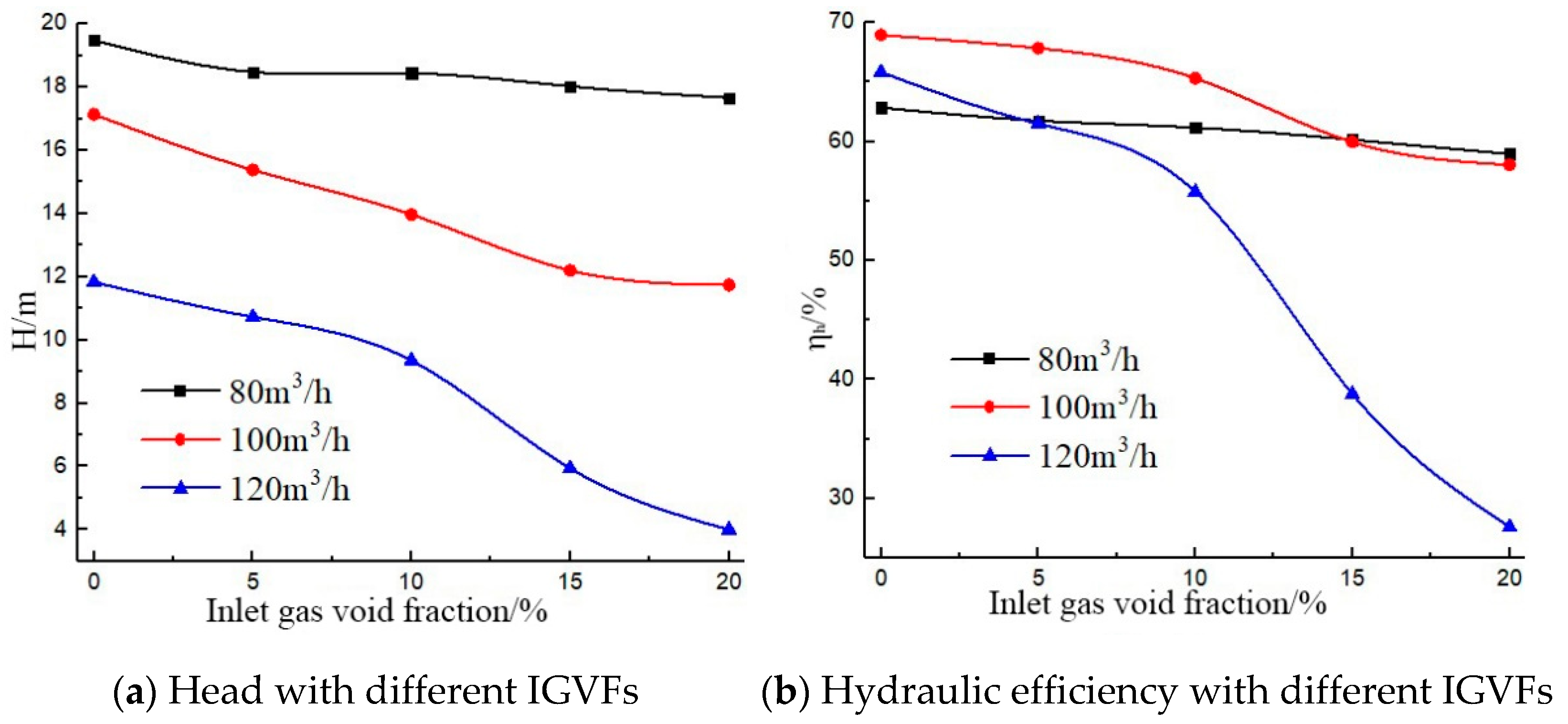
4.1. Predicted Hydraulic Performance of the Multiphase Pump

Figure 8 is the external characteristic curve of a multiphase pump under different working circumstances. In Figure 8, H is the head and η is the hydraulic efficiency. According to Figure 8a, the multiphase pump head decreases in a gradual manner with the increase of IGVF at the same flow rate, demonstrating that the increase of IGVF gradually decreases the performance capability of the pump under low IGVF. Moreover, the increase of IGVF has a relatively small impact on the head at small flow rates, whereas the head drop rate of the pump begins to increase evidently as the IGVF increases at the designed flow rate and a large flow rate. Hence, the influence of IGVF on the head at small flow rates is obviously less than that at flow rates in the design and large flow rates. For Figure 8b, the hydraulic efficiency of the multiphase pump decreases slowly with the increase of IGVF at small flow rates. It shows that the IGVF change has minor effect on its hydraulic efficiency at small flow rates. With the increase of the flow rate, there is a clear downward tendency of the pump hydraulic efficiency. However, at small flow rates, the hydraulic efficiency of the multiphase pump is affected by IGVF significantly less than the large flow rate and the flow rate in the design.

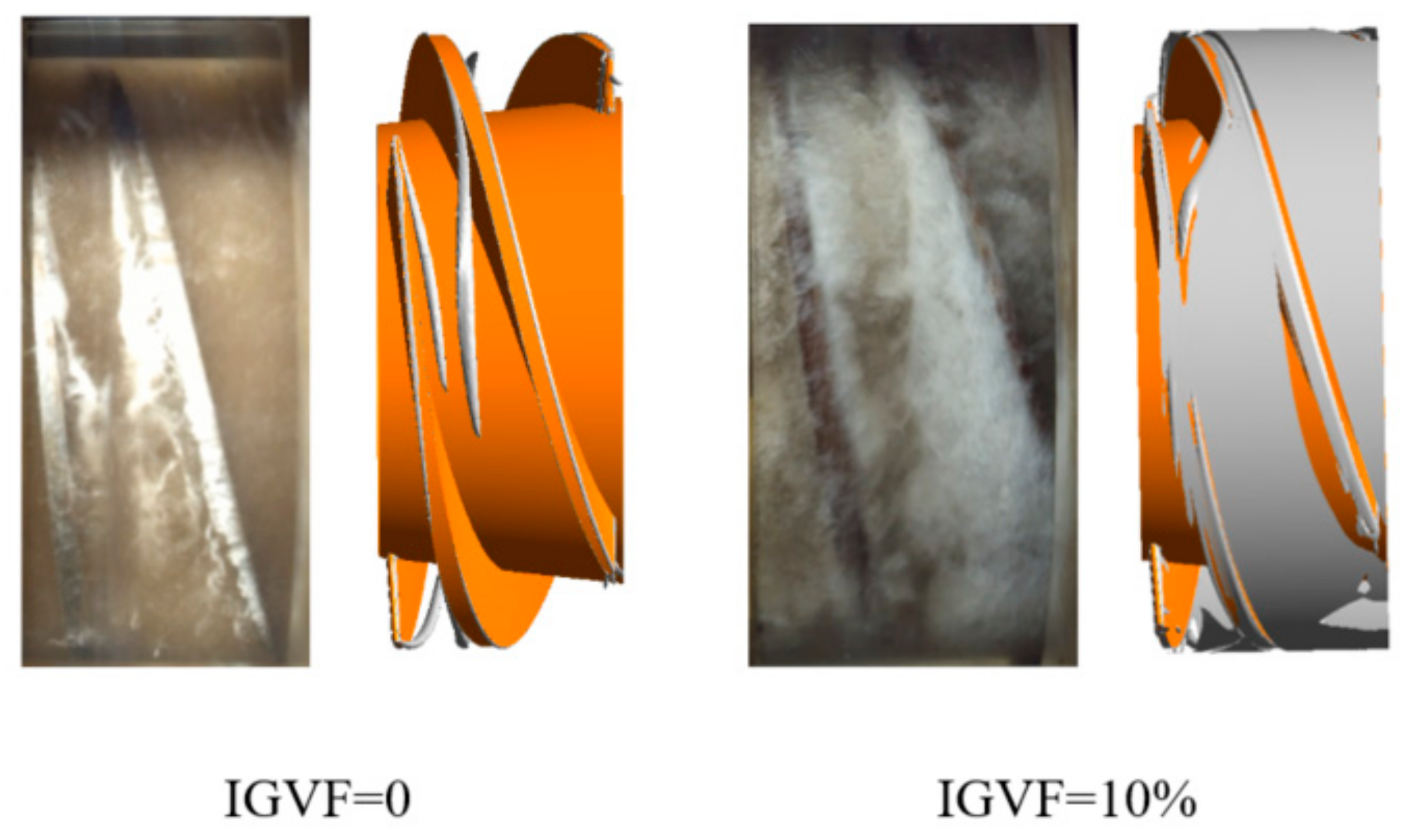
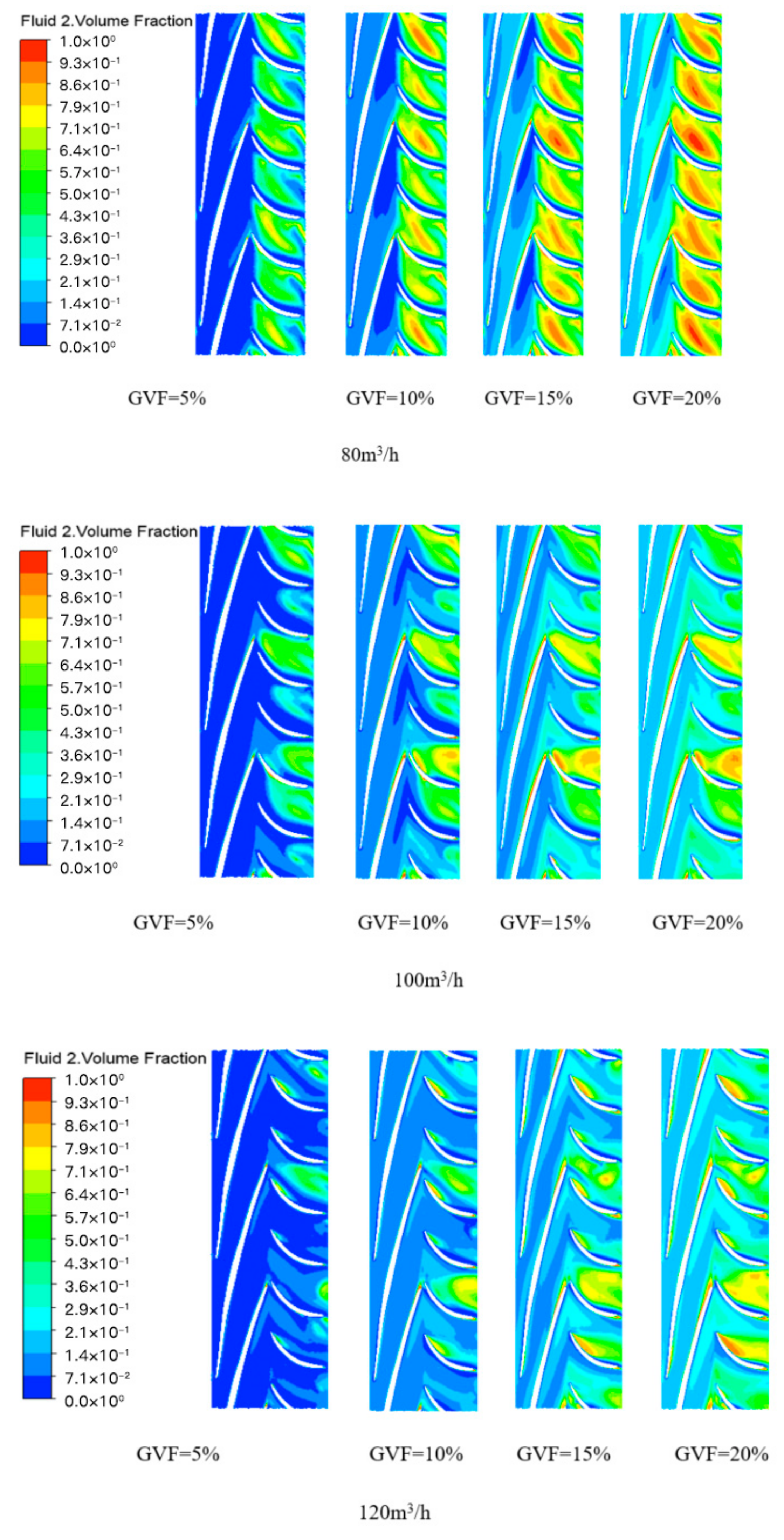
4.2. Flow Field Analysis

Figure 9 shows the pressure distribution contour of the multiphase pump at 0.5 span under different IGVF at different flow rates.
Figure 9 shows that with the same IGVF, the low-pressure area in the impeller flow passage at small flow rates mainly appears near the impeller blade SS. As the flow rate increases, the low-pressure area begins to shift from the back of the SS to the inlet area of the PS at the design rate and large flow rates. In the case of the same flow rate, with the increase of IGVF, the low-pressure area gradually reduces, which indicates that the increase of IGVF is beneficial to adverse pressure gradient change in the impeller. In addition, the pressure gradient change improves with the augment of the flow rate under the same IGVF circumstances. The low-pressure area near the inlet of the blade SS gradually reduces with the increase of IGVF at diverse flow rates.
Figure 10 presents a gas contour at 0.5 span of different IGVFs under a variety of flow rate working circumstances in the multiphase pump.
As shown in Figure 10, at various flow rates, a large-area gas accumulation phenomenon is not found in the impeller passage, while it is very obvious in the blade. Moreover, the gas accumulation phenomenon in both impeller flow passage and blade flow passage increases by degrees as the IGVF increases, which means that the gas-liquid separation phenomenon in the multiphase pump is gradually intensified following the enhancement of the IGVF at same flow rate. This is also the reason why the hydraulic efficiency of the pump gradually decreases as the IGVF increases. Furthermore, under the same IGVF, the gas accumulation phenomenon gradually decreases with the increase of the flow rate, indicating that the increase of the flow rate makes the gas-liquid two-phase mixing in the multiphase pump gradually become uniform under the same IGVF. Moreover, the gas accumulation phenomenon gradually increases at the impeller outlet near the blade SS, with IGVF increasing, eventually leading to the gradual shrinkage of the impeller flow passage and the gradual reduction of the effective water-carrying section, which increases the velocity of the fluid in the flow passage and the hydraulic loss, and decreases the hydraulic efficiency. Nevertheless, the gas accumulation phenomenon at the blade PS inlet gradually increases as the IGVF increases at large flow rate, and its increase range is smaller than the small flow rate and design flow rate.

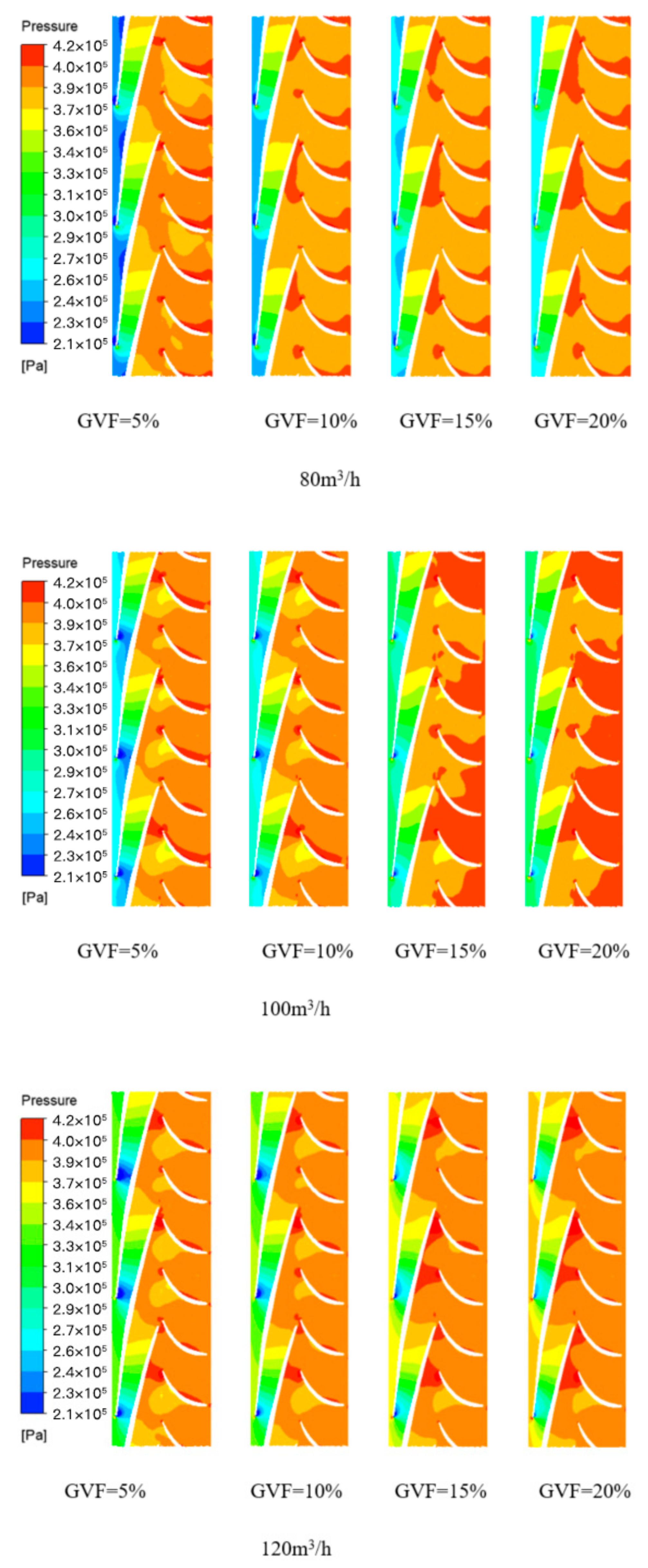
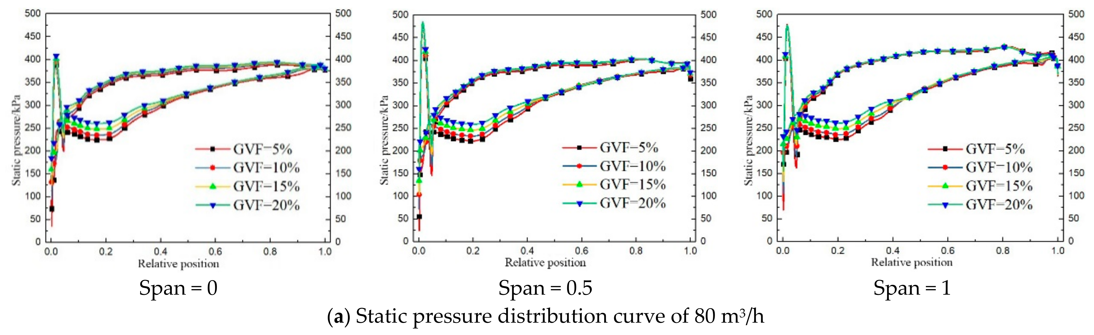
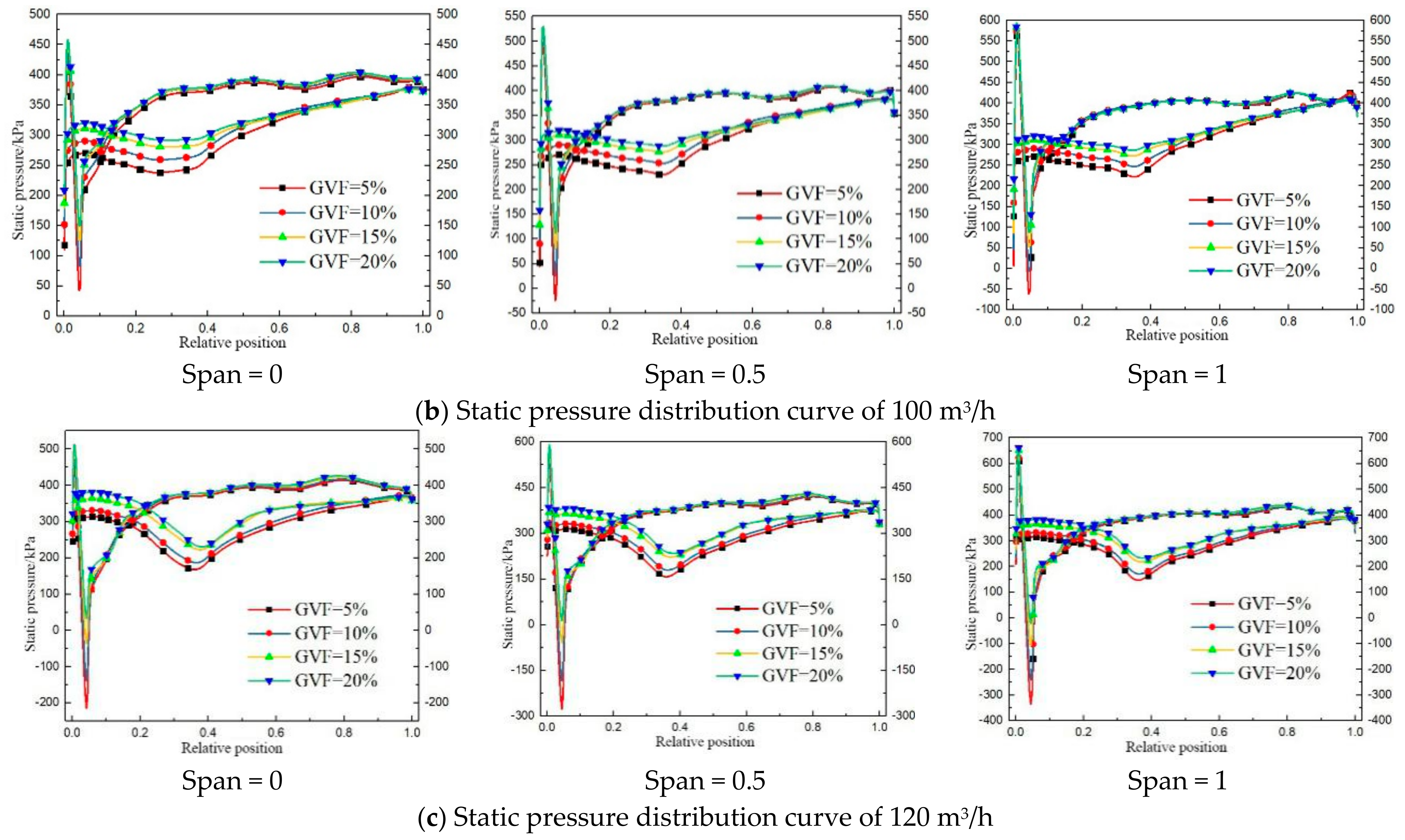
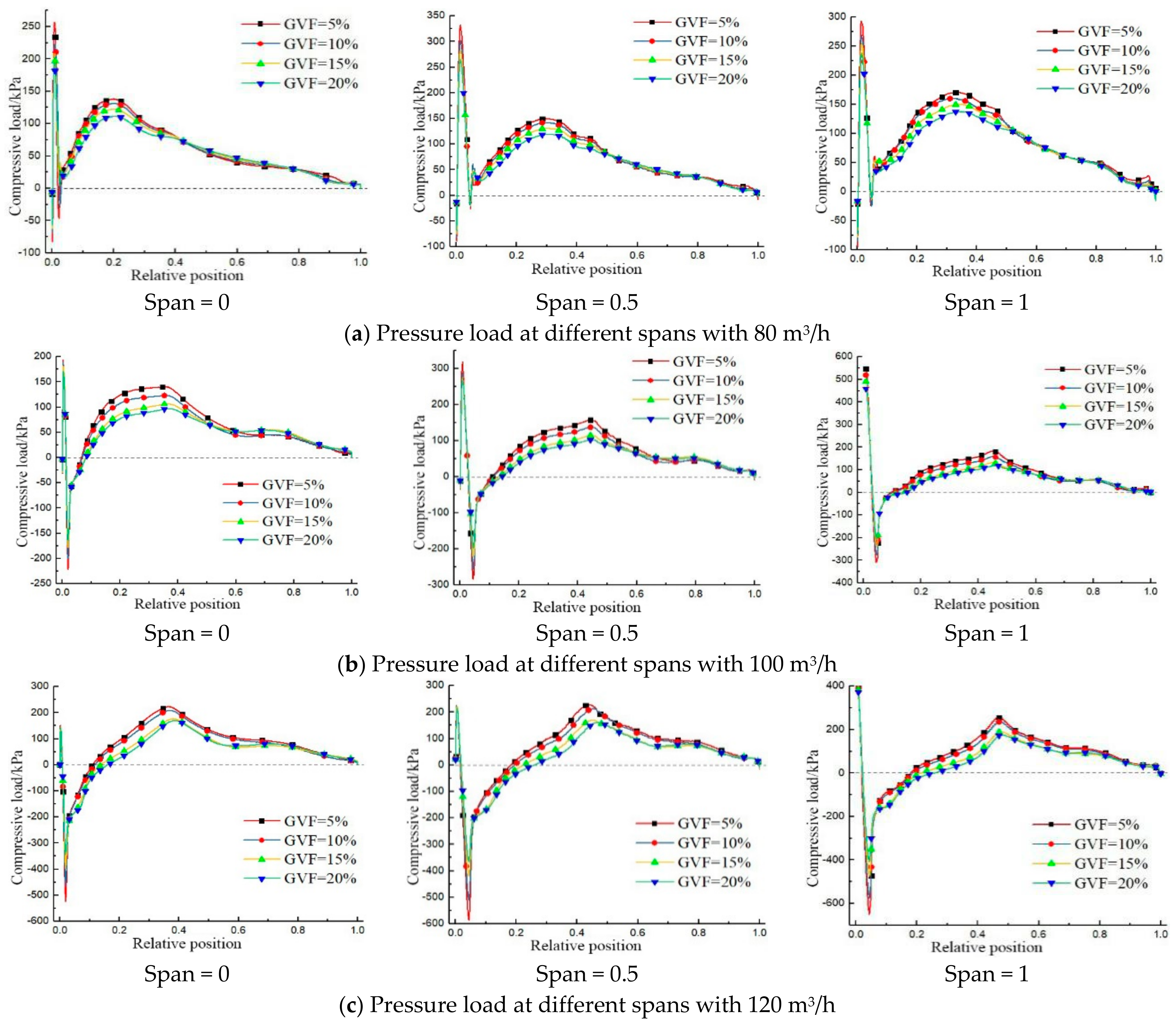
4.3. Pressure Load on the Multiphase Pump Impeller Blade

For the purpose of investigating the power ability of the multiphase pump under the gas-liquid two-phase case, different flow rates (80 m3/h, 100 m3/h, and 120 m3/h) and different IGVF (IGVF = 5%, 10%, 15%, and 20%) working circumstances were selected to analyze the power ability of the pump, by the method of extracting static pressure data from the inlet to the outlet of the blade in three streamlines on the surface of the blade at different spans as shown in Figure 2 (hub Span = 0, Span = 0.5. Span = 1). Finally, the static pressure distribution curve at the blade PS and SS of the multiphase pump and the pressure load distribution curve of impeller blades are obtained, as shown in Figure 11 and Figure 12. For every curve in Figure 11, the above curve represents the static pressure distribution curve at the blade PS, and the following curve represents the static pressure distribution curve at the blade SS.
As can be seen in Figure 11, the static pressure distribution characteristics of different streamlines on the PS of the multiphase pump impeller blades under various working circumstances are similar, the static pressure values are relatively close, and the static pressure distribution characteristics of diverse streamlines on the SS are also similar; however, the static pressure values are quite different (the upper curve represents the PS, and the lower curve represents the SS), indicating that the static pressure distribution at the PS of the pump blade is almost unaffected by the change of IGVF, while the effect of IGVF change on static pressure distribution on the SS is relatively apparent. This is because, as can be seen in Figure 9, the pressure change on the SS is obviously greater than that on the PS, so the result shown in Figure 11 is presented. In addition, the significant effect of the IGVF change on the static pressure at the SS of the multiphase pump blade at small flow rates is only at the relative position of the inlet from 0 to 0.4. As the flow rate increases at the design flow rate, the relative position of the SS is greatly affected by the change of IGVF in the range of 0 to 0.7, while this area is further enlarged at large flow rates, and the area of the SS affected by the IGVF change is in the range of 0~0.8 of the relative position, indicating that the static pressure at the blade SS is more susceptible to the influence of the IGVF at large flow rate than the small flow rate. Moreover, static pressure on the SS is larger than that on the SS at different degrees of each streamline in the inlet area at the design and large flow rates, which is not conducive to the pump power ability. Moreover, for the same flow rate, the area where the static pressure value SS is greater than the static pressure value on the PS is gradually increasing, as the IGVF of each streamline increases.
Figure 12 shows the pressure load distribution curve of the multiphase pump impeller blades. The pressure load on the blade at various spans is different; hence, the Y-axis scale is different. The pressure load of each streamline changes from the blade inlet to the outlet in a similar pattern at the same flow rate, and the impeller inlet pressure load increases suddenly. The reason is that the gas phase is subject to interference between dynamic and static surface when entering the impeller inlet, which intensifies the interaction between the gas and liquid phase, making the pressure load fluctuation in the impeller inlet becomes relatively large; however, it first increases and then decreases on the whole. It demonstrates that the pump power ability increases at first and then decreases. Moreover, the pressure load gradually decreases with the augment of the GVF at the same flow rate, and the area where the pressure load of each streamline is negative also increases gradually, indicating that the pump power ability is weakening stage by stage with the increase of the GVF. The main reason is that the gas accumulation phenomenon on the blade SS gradually becomes obvious as the GVF increases, the flow passage becomes narrower, and the gas-liquid separation in the impeller flow passage is intensified, causing the impeller power ability to weaken.
As can be seen in Figure 12, the pressure load of each streamline is almost positive at small flow rates, and the power capability case is good. With the increase of the flow rate, the blade inlet area where the pressure load is negative continuously increases at the design flow rate and large flow rates, demonstrating that the enhancement of flow rate under the gas-liquid two-phase case makes the work efficiency of the impeller inlet area reduce. In addition, the peak pressure load begins to gradually move to the outlet as the flow rate increases under the same IGVF, and the peak value gradually increases from the hub to the rim. This is on account of the relatively strong interaction between the fluid flow of the tip clearance near the rim and fluid flow at the impeller outlet, causing the pressure load at the hub to be smaller compared to that at the rim. It demonstrates that the high-efficiency area of the multiphase pump begins to shift to the impeller outlet, and the impeller power capability from the hub to shroud is increased. Moreover, with the increase of the flow rate, the area where the pressure load on the blade surface at the impeller hub, the middle streamline, and the rim that is affected by GVF gradually increase, and this area consists of the blade SS, which shows static pressure under the influence of IGVF in Figure 11. It illustrates that the IGVF change mainly has an impact on the power capability at the SS when the flow rate is same.

5. Conclusions

(1)
As the IGVF increases, the head and hydraulic efficiency of the multiphase pump all decrease gradually, and the increase of the flow rate make the gas-liquid two-phase mixing in the multiphase pump gradually uniform. Furthermore, the gas accumulation phenomenon at the impeller outlet near the blade SS gradually increases, causing the impeller flow passage to gradually shrink and the effective water-carrying section gradually to decrease. It increases both the flow velocity of the fluid in the flow passage and the pump hydraulic loss, while the hydraulic efficiency decreases.
(2)
The static pressure on the blade PS is scarcely affected by the IGVF, while the IGVF has an evident effect on the static pressure on the impeller blade SS. At small flow rates, the area that static pressure on the SS significantly affected by the IGVF change is only near the inlet. However, with an increasing flow rate, the static pressure distribution on the SS is gradually increased by the effect of gas void fraction, and it is close to the blade outlet.
(3)
The pump power capability is descended step by step as the IGVF increases, and it also descends with the increase of the flow rate at the impeller inlet. In the meantime, under the same IGVF, with the increase of the flow rate increase, the peak value of the pressure load begins to gradually move toward the outlet and its value from hub to shroud is increasing. Moreover, this peak value gradually increases from the hub to shroud, indicating that the high efficiency area of the pump begins to shift to the impeller outlet, and the impeller power capability is constantly increasing from the hub to the shroud.

Author Contributions

G.S.: Conceptualization, Methodology, Software, Writing—original draft, Writing—review and editing. D.Y.: Investigation, Software, Writing—original draft; Writing—review and editing. X.L.: Investigation, Software, Conceptualization. Y.X.: Supervision, Validation. Z.S.: Supervision. All authors have read and agreed to the published version of the manuscript.

Funding

This work was supported by the National Key Research and Development Program (2018YFB0905200), the Open Research Fund Program of State key Laboratory of Hydroscience and Engineering (sklhse-2021-E-03), the Education department key project of Sichuan province of China (Grant No. 17ZA0366), the Key scientific research fund of Xihua University of China (Grant No. Z1510417), the Open Research Subject of Key Laboratory of Fluid and Power Machinery, Ministry of Education (Grant No. LTDL2020-008), the National Natural Science Foundation of China (Grant No. 51479093), the National Key Research and Development Program of China (Grant No. 2017YFC0404200), the Key Research and Development Program of Tianjin (Grant No. 18YFZCSF00310), the Key Laboratory of Fluid and Power Machinery (Xihua University), and the Ministry of Education (Grant No. SZJJ-2018-125).

Institutional Review Board Statement

Not applicable.

Informed Consent Statement

Not applicable.

Data Availability Statement

All the data is already in the article.

Conflicts of Interest

The authors declare no conflict of interest.

References

  1. Yi, S.; Hongwu, Z.; Jinya, Z.; Jiate, Z.; Junlin, Z. Experiment and numerical study of a new generation three-stage multiphase pump. J. Pet. Sci. Eng. 2018, 169, 471–484. [Google Scholar]
  2. Shi, G.; Wang, Z.; Wang, Z.; Li, Z.; Liu, X. Research on the pressurization performance of an impeller in a multi-phase pump under different working cases. Adv. Mech. Eng. 2019, 11, 1–11. [Google Scholar]
  3. Zhang, W. Analysis of flow and phase interaction characteristics in a gas-liquid two-phase pump. Oil Gas Sci. Technol. Rev. d’IFP 2018, 73, 11. [Google Scholar] [CrossRef]
  4. Wenwu, Z.; Zhiyi, Y.; Muhammad, Z.; Yongjiang, L. Study of the gas distribution in a multiphase rotodynamic pump based on interphase force analysis. Energies 2018, 11, 1069. [Google Scholar]
  5. Shi, Y.; Yin, B.; Xu, R.; Zhang, J. Numerical investigation of two-phase flow characteristics in multiphase pump with split vane impellers. J. Mech. Sci. Technol. 2019, 33, 1651–1661. [Google Scholar]
  6. Li, C.H.; Luo, X.Q.; Feng, J.J.; Zhu, G.J.; Xue, Y.G. Effects of Gas-Volume Fractions on the External Characteristics and Pressure Fluctuation of a Multistage Mixed-Transport Pump. Appl. Sci. 2020, 10, 582. [Google Scholar] [CrossRef] [Green Version]
  7. Jinsong, Z.; Lei, T. Energy Performance and Pressure Fluctuation of a Multiphase Pump with Different Gas Volume Fractions. Energies 2018, 11, 1216. [Google Scholar]
  8. Cui, B.; Li, W.; Zhang, C. Effect of Blade Trailing Edge Cutting Angle on Unstable Flow and Vibration in a Centrifugal Pump. J. Fluids Eng. 2020, 142, 101203. [Google Scholar] [CrossRef]
  9. Zhang, W.; Zhu, B.; Yu, Z. Characteristics of bubble motion and distribution in a multiphase rotodynamic pump. J. Pet. Sci. Eng. 2020, 193, 107435. [Google Scholar] [CrossRef]
  10. Yan, S.; Sun, S.; Luo, X.; Chen, S. Numerical Investigation on Bubble Distribution of a Multistage Centrifugal Pump Based on a Population Balance Model. Energies 2020, 13, 908. [Google Scholar] [CrossRef] [Green Version]
  11. Shi, G.; Liu, Z.; Xiao, Y.; Wang, Z.; Luo, Y.; Luo, K. Energy conversion characteristics of multiphase pump impeller analyzed based on blade load spectra. Renew. Energy 2020, 157, 9–23. [Google Scholar] [CrossRef]
  12. Han, L.; Su, Z. Effect of thickness ratio coefficient on the mixture transportation characteristics of helical–axial multiphase pumps. Appl. Sci. 2020, 10, 345. [Google Scholar] [CrossRef] [Green Version]
  13. Yue, H.; Lei, T.; Yabin, L.; Yun, X.; Jinsong, Z.; Baoshan, Z. Energy Performance and Radial Force of a Mixed-Flow Pump with Symmetrical and Unsymmetrical Tip Clearances. Energies 2017, 10, 57. [Google Scholar]
  14. Zhang, J.S.; Fan, H.G.; Zhang, W.; Xie, Z.F. Energy performance and flow characteristics of a multiphase pump with different tip clearance sizes. Adv. Mech. Eng. 2019, 11. [Google Scholar] [CrossRef]
  15. Monte Verde, W.; Biazussi, J.L.; Sassim, N.A.; Bannwart, A.C. Experimental study of gas-liquid two-phase flow patterns within centrifugal pumps impellers. Exp. Therm. Fluid Ence 2017, 85, 37–51. [Google Scholar] [CrossRef]
  16. Xu, Y.; Cao, S.; Sano, T.; Wakai, T.; Reclari, M. Experimental investigation on transient pressure characteristics in a helico-axial multiphase pump. Energies 2019, 12, 461. [Google Scholar] [CrossRef] [Green Version]
  17. Liu, M.; Tan, L.; Xu, Y.; Cao, S. Optimization design method of multi-stage multiphase pump based on oseen vortex. J. Pet. Ence Eng. 2020, 184, 106532. [Google Scholar] [CrossRef]
  18. Ming, L.; Lei, T.; Shuliang, C. Design Method of Controllable Blade Angle and Orthogonal Optimization of Pressure Rise for a Multiphase Pump. Energies 2018, 11, 1048. [Google Scholar]
  19. Li, C.; Luo, X.; Feng, J.; Zhu, G.; Yan, S. Effect of Diversion Cavity Geometry on the Performance of Gas-Liquid Two-Phase Mixed Transport Pump. Energies 2020, 13, 1882. [Google Scholar] [CrossRef]
  20. Jun-Won, S.; Jin-Woo, K.; Young-Seok, C.; Jin-Hyuk, K.; Won-Gu, J.; Kyoung-Yong, L. Multi-objective optimization of the hydrodynamic performance of the second stage of a multi-phase pump. Energies 2017, 10, 1334. [Google Scholar]
  21. Cao, S.; Peng, G.; Yu, Z. Hydrodynamic Design of Rotodynamic Pump Impeller for Multiphase Pumping by Combined Approach of Inverse Design and CFD Analysis. J. Fluids Eng. 2005, 127, 330–338. [Google Scholar] [CrossRef]
  22. Hu, H.; Li, X.K.; Gu, B. Hydraulic Optimization of Multiphase Pump Based on CFD and Genetic Algorithm. Int. J. Mesh Distrib. Comput. 2015, 8, 161–169. [Google Scholar]
Figure 1. Computational model.
Processes 09 00650 g001
Figure 2. Impeller spans. 1. Hub, 2. 0.5 span, 3. Shroud.
Processes 09 00650 g002
Figure 3. Schematic diagram of structured mesh.
Processes 09 00650 g003
Figure 4. Fluid domain mesh.
Processes 09 00650 g004
Figure 5. Mesh independence verification.
Processes 09 00650 g005
Figure 6. Schematic of the multiphase pump test rig.
Processes 09 00650 g006
Figure 7. Comparison of the experimental flow field and simulated flow field.
Processes 09 00650 g007
Figure 8. External characteristic of the multiphase pump under various circumstances.
Processes 09 00650 g008
Figure 9. Static pressure distribution of multiphase pump under different circumstances.
Processes 09 00650 g009
Figure 10. Gas in multiphase pump under different circumstances.
Processes 09 00650 g010
Figure 11. Static pressure distribution curve of multiphase pump under various circumstances.
Processes 09 00650 g011aProcesses 09 00650 g011b
Figure 12. Pressure load distribution curve of multiphase pump under various circumstances.
Processes 09 00650 g012
Table 1. Settings of the boundaries and solution.
BoundariesParameters
InletVelocity inlet
OutletStatic pressure outlet
Wall surfaceNo slip wall
Working mediumGas, water
Stator interfaceGeneral connection
Rotor-stator interfaceFrozen Rotor
Convergence criterion1 × 10−5
Publisher’s Note: MDPI stays neutral with regard to jurisdictional claims in published maps and institutional affiliations.

