Abstract
Wettability patterning of a surface is a passive method to manipulate the flow and heat transport mechanism in many physical processes and industrial applications. This paper proposes a rational wettability pattern comprised of multiple superhydrophilic wedges on a superhydrophobic background, which can continuously remove the impacted spray droplets from the horizontal surface. We observed that the spray droplets falling on the superhydrophilic wedge region spread and form a thin liquid film, which is passively transported away from the surface. However, most of the droplets falling on the superhydrophobic region move towards the wedge without any flooding. The physics of the passive transport of the liquid film on a wedge is also delved into using numerical modelling. In particular, we elucidate the different modes of droplet transport in the superhydrophobic region and the interaction of multiple droplets. The observed droplet dynamics could have profound implications in spray cooling systems and passive removal of liquid from a horizontal surface. This study’s findings will be beneficial for the optimization of efficient wettability patterned surfaces for spray cooling application.
1. Introduction
The impact of a liquid drop on a solid surface is ubiquitous and observed in many natural and industrial processes. The interplay of several parameters such as drop velocity, diameter, viscosity, surface tension, and surface wettability makes the drop impact phenomena complex and fascinating [1]. Although several parameters influence the drop impact dynamics; the surface wettability has an especially important role. Depending on the surface wettability, the impacted droplet can jump (rebound), deposit, or splash [2,3]. Spray cooling is one of the important practical applications of drop impact on a surface and it has received significant attention in the present decade due to the emergence of high heat-flux electronic components [4]. The overall heat transfer coefficient of the spray impingement cooling systems depends on the contact time and flow dynamics of the impacting drops. The efficiency of the spray cooling system relies on continuous removal of impinged droplets and optimum contact time of the drop. The flow dynamics and contact time of drops depend on the wettability of the surface and can be engineered either by a manipulation of surface textures, chemical treatment (coating) or a combination of both.
In general, poly-dispersed spray consisting of different sized microdroplets with a wide range of impact velocities is used for spray cooling. During the impact, momentum and energy exchange between the impacting droplets and the solid surface make the spray impact process very complicated. The dynamics of a single drop impact on a solid surface governed by surface wettability, Weber number, (ratio between inertia to surface tension force) and Reynolds number, (ratio between inertia and viscous force) [1,2]. Antonini et al. studied the effect of wettability ranging from hydrophilicity to superhydrophobicity on drop impact dynamics with a wide range of Weber numbers [5]. The splashing of the impacted drop initiates at higher impact Weber number and leads to the breakup of the impacted droplet into multiple tiny droplet [6,7]. In practical applications, along with the impact dynamics of a single drop, multi-drop impact and interactions are also important [8]. The merged droplet can jump from a superhydrophobic surface due to the conversion of the excess surface energy of the coalesced droplet into kinetic energy [9]. The impact and coalescence dynamics on a superhydrophobic surface are fascinating, and surface engineering can control it [10,11].
The wettability of a surface is widely expressed by two parameters: contact angle and contact angle hysteresis (CAH) [12]. At the initial stage of spray impact on a hydrophilic surface, a large amount of heat is transferred to the impinged drops as the drops directly contact with the heated surface. After prolonged spray impact, the impacted droplets spread and form a liquid film over the surface, which increases the thermal resistance. This film causes a reduction in the heat transfer efficiency [13]. On the other hand, the impacted droplets on a superhydrophobic surface continuously bounce off from the surface due to low adhesion force. The bouncing phenomena reduces the contact time with the heated surface and results in the lower heat transfer performance [14] on superhydrophobic surface. The overall efficiency of spray cooling system relies on how long the impacted droplets are in contact with the heated surface and how fast the heated droplets drain from the surface. The optimum control of these two parameters can be manipulated by surface modifications. A hybrid surface with a combination of circular and radial grooves, with a depth and width of 500 μm was showed to result in 34% enhancement in critical heat flux (CHF) compared to the surfaces with straight grooves [15]. In another study, a hybrid surface comprising micro/nanostructures showed 59% enhancement in CHF compared to a flat surface [16]. The reported enhancement in CHF with micro/nanostructures is encouraging and fundamental understanding of the role of micro/nanostructures on the flow behaviour during spray impact is vital to fabricate surfaces for efficient spray cooling.
In recent years, surfaces with wettability patterns have received much attention, particularly in applications such as condensation [17,18], boiling [19], fog harvesting [20], self transport of drops [21,22,23], liquid mixing [24], etc. The main benefit of wettability patterns is that they can enable harnessing the advantages of both hydrophobicity and hydrophilicity in the transport process. The design of efficient wettability patterned surfaces requires a more fundamental understanding of the underlying physical phenomena. For example, the self-transport of drop on a wedge track, wettability gradient surface, and topological liquid diode without any external energy can have profound implications in a large spectrum of engineering applications. The Laplace pressure difference, between the narrow to the wider region, propels the drop from narrow to wider region in a wedge track [22]. In case of surfaces with wettability gradient, the difference in front and back contact angles propels the drop from the hydrophobic to the hydrophilic side [25]. The transport velocity and length are limited in these approaches. However, the long-distance transport of droplets at a higher velocity can be achieved using the topological liquid diode concept. In this concept, the surface’s topological structure breaks the contact line pinning at the advancing edge of the drop and simultaneously arrests the reverse motion of the drop by strong pinning. It allows rapid transport of the droplet at a longer distance [26]. Schutzius et al. proposed a novel approach for manipulating the drop impact dynamics by surface patterns [27]. They showed droplet vectoring and morphing on a non-wetting surface consist of different shaped wettable patterns (circular ring, circular arc, cross pattern, etc.). In a recent work, drop impact on a bi-phobic (hydrophobic spots on the superhydrophobic background) heated surface was investigated [28]. The study found a 33–46% enhancement in cooling efficiency for bi-phobic surface compared to the superhydrophobic surface. However, the cooling efficiency of the bi-phobic design was lower than the plain hydrophobic surface since the impacted drops were trapped inside the hydrophobic spots while receding. In another study, directional impingement cooling was investigated using a wedge-shaped superhydrophilic track on a superhydrophobic surface [29]. The spreading of the impinged jet through the wedge along with the drainage at the wider edge increased the two-phase heat transfer efficiency by a factor of 4.
In spray cooling, the superhydrophobic surfaces show poor cooling efficiency due to droplet rebound and mobility on them. On the other hand, a hydrophilic surface is prone to flooding with prolonged spray impact, which again reduces the cooling efficiency. Therefore, a hybrid, wettability patterned surface may have better cooling efficiency compared to both superhydrophobic and hydrophilic surface. Through a rational wettability patterning, efficient hybrid surfaces applicable for spray cooling can be designed to exploit self-transport of impinged drops. In the present study, we propose and investigate a design that consists of multiple superhydrophilic wedge tracks on a superhydrophobic background. The fabricated design can passively remove the impinged water drops from a horizontally oriented surface. In the first, proof of concept characterization presented here, we observed a continuous flow of impinged droplets through the wedge track of the surface without any flooding issues even after prolonged testing. The flow dynamics is carefully analysed and the different transport modes of the impinged droplets from superhydrophobic to superhydrophilic region are identified. A numerical study has also been performed to explain the physics of the droplet transport on a single superhydrophilic wedge with a superhydrophobic background. The robustness and prolonged sustenance of self-propelled liquid drainage clearly points to the potential of future exploitation of our surfaces in spray cooling application.
2. Material and Methods
2.1. Surface Preparation and Characterization
We used Aluminium-6061 alloy of size 40 mm × 40 mm × 3 mm as substrate. Figure 1 summarizes the fabrication steps of wettability patterns proposed in this work. The polished substrate was ultrasonically cleaned in a mixture of ethanol, acetone and DI water at room temperature and dried by blowing nitrogen gas. The ultrasonically cleaned sample was then microtextured by chemical etching using 3 M hydrochloric acid for 5 min and further cleaned in a DI water bath. After that, nanotexturing of the microtextured aluminium sample was performed by immersing in DI water at a temperature of 100 °C for 1 h. A hierarchical surface morphology consisting of micro/nanostructures was obtained by using these steps and the contact angle of the surface reached nearly zero. Next, the sample was spray-coated with commercial Glaco solution (colloidal solution of SiO2 nanoparticles in isopropanol solution) and dried in room temperature for around 2 h to achieve superhydrophobicity. Then the final wettability patterns were obtained using a 60 W CO2 laser engraver (VLS 3.60, Universal Lasers) with a spot size of 30 μm. We used 90% of power and 5% of laser speed during laser ablation. The laser-ablated areas were transformed to superhydrophilic after the laser ablation and the unexposed area remained as superhydrophobic.
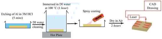
Figure 1.
Fabrication steps for the wettability patterns on a superhydrophobic surface.
The micro/nanostructures and the surface chemistry of the interface has an important role in the wetting and flow dynamics during spray impacts. The surface morphology was analyzed using a scanning electron microscope (Apreo-Thermofisher Scientific, USA) and surface profilometer (Nanomap 1000WLI- AEP technologies). The wettability of the surface was characterized with a contact angle meter (KRUSS-DSA25) using a 5 μL sessile drop. The contact angle of the surface after micro/nano texturing followed by Glaco spray coat reached . The initial surface morphology after chemical etching followed by hot water immersion consisted of a two-tier texture (Figure 2a,b). The microstructures are random and height and spacing between micro-asperities are μm and μm, respectively. The second tier texture is in the shape of flower petals (Figure 2c) with a width of 15–30 nm and length of 100–300 nm. During Glaco spray coating, the colloidal solution was completely spread over the whole surface evenly. The alcohol in the solution evaporated with time and the SiO2 nanoparticles of size 20–50 nm were deposited on the petal-shaped nanostructures, as can be seen from Figure 2d. The petal-shaped sharp nanostructures have disappeared in Figure 2d, since the size of the deposited nanoparticles are bigger than the width of the petal-shaped structures. Thus, the initial two-tier texture was modified to three-tier texture after Glaco spray coat. The contact angle hysteresis of the Glaco coated surface was . The average roughness of Glaco coated surface was μm (Figure 2e).
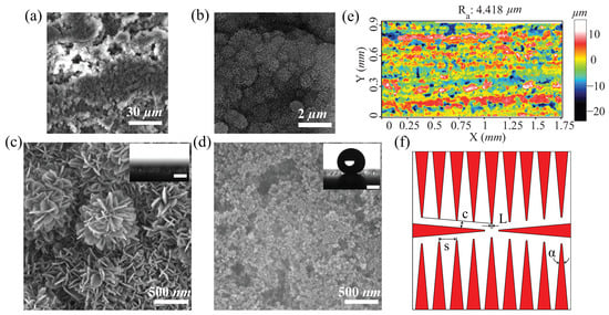
Figure 2.
SEM images of modified surface at different resolutions (a–c) after micro/nano texturing (d) after Glaco coating (superhydrophobic) (e) profilometer micrograph of Glaco coated surface (f) CAD drawing of the proposed design L = 0.35 mm, c = 2 mm, s = 5 mm, = 10°. Red shading represents the laser ablated region. The insets in (c,d) shows the contact angle of the modified surface (it is zero on laser ablated area, before Glaco application). Scale bar in contact angle snapshot is 1 mm.
The design of wettability patterns which can enhance the spray cooling efficiency is an optimization problem. The cooling efficiency also depends on the spray parameters such as the average diameter of the spray drops, the flow rate of the spray, mean velocity of the spray, etc. We hypothesize that optimized spray cooling surface should possess the following characteristics: (1) continuous removal of impacted droplet without liquid flooding, (2) optimum contact time requirement for the impacted droplet to efficiently transport heat. To investigate the role of these characteristics, we fabricated multiple wettability patterned surfaces and studied the flow dynamics during spray impact. From these experiments, we were able to obtain a wettability pattern which can remove the impacted water drop from the horizontally oriented surface without flooding. The detailed procedure of the design of the wettability pattern is discussed in Appendix A. Figure 2f shows the proposed design, which consist of multiple wedge shaped superhydrophilic tracks in a superhydrophobic surface. The wedge shaped track ensures the self transport of fluid and should enable efficient removal of heat from the surface. The replacement of heated fluid by unheated spray drops will increase the heat transferred from the surface to the spray drops, thereby facilitating overall increase in the cooling efficiency. In the proposed design ∼60% area was superhydrophobic and remaining ∼40% area was superhydrophilic. The wedge angle is 10°, spacing between wedges, S = 5 mm, the width of the narrower end, L = 0.35 mm, as illustrated in Figure 2f. The fluid in the wedge tracks is self propelled from narrower end to wider end owing to Laplace pressure difference.
2.2. Experimental Setup
Figure 3 represents the schematic of the experimental setup. The spray rig was built on top of a vibration isolation optical table. The spray rig consisted of an atomizer holder, pressure indicator, pressure regulator valves, pipes and other flow control units to supply pressurized fluids to the atomizer. Inline sub-micron filters were used in the supply line to remove the impurities in the fluids. An air-assist atomizer was used. Air and DI water were used as the working fluids. The air was supplied at 2 bar pressure (P) to atomize the liquid. The DI water flow rate was maintained at 0.5 mL/s. The spray droplets were poly-disperse. The spray was characterized using Phase Doppler Particle Analyzer (PDPA) and high-speed imaging (HSI).
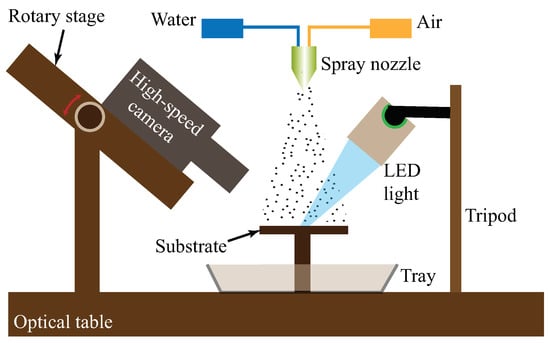
Figure 3.
Schematic illustration of the experimental setup for spray impact test. The air pressure at inlet of the spray nozzle was 2 bar and DI water flow rate was 0.5 mL/s.
2.2.1. Phase Doppler Particle Analyzer
A TSI™ 1-D PDPA system was used to simultaneously measures the drop size and axial velocity of the spray. The PDPA system works on the principles of light scattering interferometry. It is a point-based measurement technique which is non-intrusive and provides the accurate drop size and velocity measurements. The laser transmitter system generates two laser beams, which are allowed to intersect with each other at an angle to create the measurement volume. As a droplet passes through the measurement volume, it generates signal on to detectors. The droplet velocity is measured by detecting the Doppler frequency and the droplet size is measured from the phase shift between the Doppler burst signal of different detectors. The PDPA optical settings were set as in Dhivyaraja et al. [30].
2.2.2. High-Speed Imaging
A Phantom™ VEO-340L high-speed camera was used to capture the spray impact and droplet transport dynamics on the wettability patterned surfaces. The recording rate was 10,000 with the image resolution of pixels. Nikkor™ 105 mm fixed focal length macro lens was used, offering a resolution of 1 pixel μm. The camera was mounted on a rotational stage to capture the images at an angle of . A constellation™ 120 high-power LED strobe light was used to illuminate the spray region and the light source was synchronized with the high-speed camera.
3. Results and Discussion
3.1. Spray Impact
Liquid behavior on a horizontal, wettability patterned surface during spray impact is presented in Figure 4. The wettability pattern consist of 20 superhydrophilic wedges on a superhydrophobic background. The contact angle on the superhydrophobic part was whereas the contact angle on the superhydrophilic wedge was ∼0°. The wedges are placed on the surface in such a way that the wider part of the wedge is towards the edge of the surface. The liquid deposited on a wedge moves towards the wider part of the wedge due to the Laplace pressure developed between the front and back of the liquid [22]. As the spray is the collection of droplets, during the spray impact, a collection of droplets falls on the surface continuously. The part of spray drops impacting on the superhydrophilic wedge quickly converted into a liquid film, whereas the droplets falling on the superhydrophobic region spontaneously moved towards either the superhydrophilic wedge or jumped-off from the surface. There are different modes of droplet transport from superhydrophobic region to the superhydrophilic wedge which is discussed in the next section. In the wedges, once the liquid film is thick enough to overcome the pinning force of sharp edge, the liquid film drains out from the wedges.
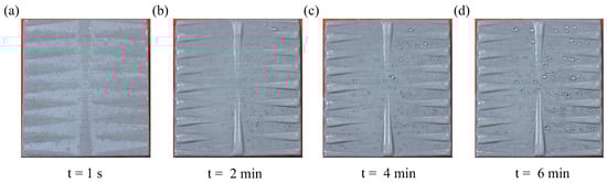
Figure 4.
Image sequences of liquid behavior on the patterned surface during spray impact. The size of the surface is 40 mm × 40 mm.
We performed continuous spray impact on the surface for 6 min from a height of 125 mm, at a pressure of P = 2 bar, with flow rate 0.5 mL/s. The drop size and velocity measurements were obtained at the same distance from the nozzle exit. The resulting droplet size varied from 0.1 μm to 115.6 μm and the number-based mean diameter was 12 μm. The droplet axial velocity varied from −1.65 m/s to 46.64 m/s and the mean axial velocity was 16.75 m/s. The droplet size and the axial velocity distribution of the poly-dispersed spray is presented in Figure A1 (see Appendix B). Figure 4a shows that at s the droplet on the superhydrophilic wedge forms a thin liquid film whereas the droplets on the superhydrophobic regions remains as a droplet. At min, the formation of liquid film on the wedges is complete (with its characteristic bulge shape) and becomes stable, the liquid drains out continuously through the wider section of the wedge. The snapshots at min, min and 6 min (Figure 4b–d) show that the liquid volume on the surface remains identical, indicating that the liquid on the surface is being continuously replaced. This continuous replacement of liquid from the surface has advantages in spray cooling.
3.2. Modes of Droplet Transport
We defined non-dimensional droplet diameter as and non-dimensional droplet velocity , where is the mean diameter of the droplet, u is its impact velocity and is the characteristic drop impact velocity scale. Figure 5a suggests that a particular diameter (d) droplet has a range of impact velocities. Depending on the and of the droplet, the dynamics of the drop impact phenomena is different for each drop [1]. The splashing (i.e., breakup into multiple secondary droplets) of the droplet is not only due to the dominance of the kinetic energy over the surface energy, but depends on the surface roughness. The occurrence of the splashing phenomena on a superhydrophobic surface during drop impact can be characterized by a parameter called splashing ratio [31,32], where is a constant which depends on the angle between the lifted liquid sheet (ejecta) and the substrate at the moment of splashing [31], is the dynamic viscosity of air, is the density of water, d is the diameter of the droplet, u is the droplet impact velocity and is the surface tension of water. The critical splashing ratio corresponds to the value of above which the impacted droplet splashes on the surface (called splashing regime) whereas, the value of represents the non-splashing regime. Santiago et al. [32] identified a critical value of for a superhydrophobic surface with different average roughness value . Based on their work, we approximated the critical value of as ∼0.055 [32]. This implies that for , the impacted droplet should not splash and for the impacted droplet should splash and break into multiple secondary droplets. As shown in Figure 5b, most of the impacted drops in the present work splash once they fell on the superhydrophobic region. A secondary droplet from the splashing can jump or roll on the surface, and it exchanges energy and momentum with the other drops during coalescence. Furthermore, the coalesced drop can jump, roll or deposits on the surface based on the magnitude of the kinetic energy. If a droplet of radius impacted with an initial velocity of u on a droplet of same radius () then the droplet can jump off from the surface after coalescence with a maximum velocity of v which can be calculated from energy conservation principle. We defined the kinetic energy of the merged drop , the kinetic energy of the impacted droplet and the change in surface energy before and after coalescence , where m is the mass of the impacted droplet and the radius of the merged drop is which is calculated from the mass balance. Thus, the maximum velocity v becomes . Therefore, the maximum theoretical jumping velocity will be in the range of 5–30 m/s. However, the actual velocity will be much lower due to the hydrodynamic losses and the formation of secondary droplets.
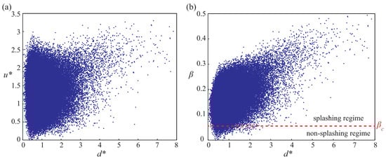
Figure 5.
(a) Spray characteristics in terms of non-dimensionless velocity () and non-dimensionless diameter () (b) Representation of the impacted poly-dispersed droplets on the superhydrophobic surface in the splashing and non-splashing regimes.
During spray, the fluid that comes out from the nozzle consists of air and water, with the water flowing at the center and air at the periphery. Depending on the pressure, the water column breaks due to the air shear flow at different locations away from the nozzle. In a air-assist atomizer, high air pressure on the nozzle produces an early breakup of the water column. The breakup of the water column due to air shear flow generate secondary droplets and the rolling motion of the droplets in the air. During spray impact on a surface, the effect of air shear flow on the dynamics of different-sized droplets is quite complex. On the surface, due to the air shear flow, droplets can rotate on the superhydrophobic surface and can be detached from the surface. Furthermore, air shear flow has a significant influence on the impact, splashing, and coalescence dynamics. The effect of air shear flow on a single droplet’s dynamics on a surface has been reported in [33,34] for different wettability conditions.
The dynamics of the droplet transport on the wettability patterned surface is quite complex. The poly-dispersed droplets falling on the wettability patterned surface had different modes of transport depending on their location of impact. This section presents different droplet transport modes on the pattern surface and how the impacted drops drained from the horizontal surface. The droplets which fell on the superhydrophilic wedge region merged with the liquid film present on the wedge and were directed towards the wider section of the wedge, and finally drained out from the surface as discussed in the previous section. The droplets which fell near the boundary of the wedge (wedge side-edges) splashed the liquid and introduced oscillations in the liquid pool present in the superhydrophilic wedge. On a few occasions, the liquids overcame the hydrophobic barrier and engulfed the tiny droplets present near the border of the wedge, as shown in Figure 6 (Video S1). However, the oscillations gradually died down through viscous dissipation, and the liquid film returned to the superhydrophilic region.
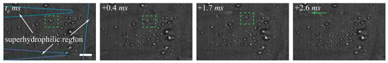
Figure 6.
The phenomena of wrapping up a droplet by the liquid pool due to the crown splashing generated while the droplet falls near the boundary of the liquid pool. Green dashed region marks the region of interest. Blue solid line represents the wettability contrast border line. Scale bar is 1 mm.
Figure 7 shows the droplet transport mechanism from the superhydrophobic region to the superhydrophilic region due to the interaction of a falling droplet with stationary droplets present on the superhydrophobic region (Video S2). When a droplet fell on a stationary droplet, they coalesced and splashed. After the splashing, the droplet rebounded and lifted-off from the surface (see the event (i) in Figure 7). This lifting of the coalesced droplet is due to the conversion of excess surface energy gained from the coalescence to kinetic energy [9,35]. The lifting droplet may come in the path of a flying droplet and merge, as shown in the event (ii) of Figure 7. The lifting droplet fell again on the superhydrophobic region or in the liquid pool due to gravity. The event (ii) in Figure 7 shows that when the lifting droplet fell near the wedge border, it coalesced with the liquid pool. The event (iii) in Figure 7 shows that the accumulated volume of liquid on the wedge forms a bulge shape and the liquid moves towards the wider section of the wedge due to the Laplace pressure difference. The yellow arrow in Figure 7 shows the direction of the bulge motion on the wedge.
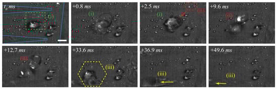
Figure 7.
The time-lapse snapshots capturing: (i) coalescence, splashing and lifting phenomena when the droplet fell to a stationary droplet (ii) coalescence of the lifting droplet with another flying droplet (iii) merging of the lifting droplet with liquid pool and self transport in the wedge. Dashed region marks the region of interest. Blue solid line represents the wettability contrast border. Scale bar is 1 mm.
Figure 8 shows the droplet transport mechanism from the superhydrophobic to the superhydrophilic region due to the secondary droplet generated during splashing. The secondary droplets generated from splashing either flew off or rolled on the superhydrophobic region and finally merged with the liquid pool (Video S3). Few secondary droplets generated from the splashing struck the stationary droplet present on the surface and coalesced. The stationary droplet gained the kinetic energy from the striking secondary droplet and started rolling on the surface, as shown in the event (i) of Figure 8. While rolling, the droplet coalesced with other droplets present in its path, as shown in the event (ii) of Figure 8. During the coalescence, the droplet also gains energy due to reduction in surface energy. The excess surface energy converts into kinetic energy, and thus the droplet rolls further on the surface. Finally, the accumulated droplet volume touched the liquid pool and merged with the liquid pool due to the capillary pumping, as shown in the event (iii) of Figure 8. It was observed that the merged liquid volume forms a bulge shape and moved towards the wider section of the wedge. The liquid pool continuously drained out from the surface through the wider section of the wedge.
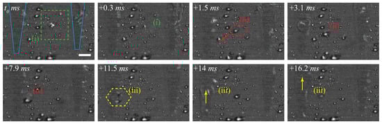
Figure 8.
The time-lapse snapshots capturing: (i) the collision of secondary droplet generated from the splashing with a stationary droplet, (ii) rolling of coalesced droplet and subsequent coalescence with other droplets while it is in motion, (iii) finally coalescence with the liquid pool and self transport in the wedge. Dashed region marks the region of interest. Blue solid line represents the wettability contrast border. Scale bar is 1 mm.
The passive liquid transport on a wedge can be better understood by performing a separate experiment by placing a droplet on the narrower region of the superhydrophilic wedge with a thin liquid film laid on a superhydrophobic background. We considered the same dimension of the wedge in Figure 1f. The droplet front position was recorded at a frame rate of 900 using the high-speed camera. We calculated the droplet transport velocity (V) from the temporal data of X. Figure 9 shows the temporal variation of droplet transport velocity (V) and droplet front position (X) on the wedge for four different droplet volumes (0.5 μL, 1 μL, 2 μL and 4 μL). The droplet’s transport velocity reaches a peak during the initial release of the droplet on the wedge; it decreases drastically and reaches a steady-state in all cases. The peak velocity V for 0.5 μL, 1 μL, 2 μL and 4 μL are 0.71 m/s, 0.92 m/s, 1.08 m/s and 1.2 m/s respectively as shown in Figure 9a,b. A droplet of volume 0.5 μL spans 5.9 mm on the wedge, 1 μL droplet 7.9 mm, 2 μL droplet 12.5 mm whereas, a 4 μL droplet spans till the end of the track (20 mm). It was observed that a higher volume droplet spreads faster because of the high inertia during the initial release of the droplet on the wedge.
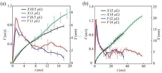
Figure 9.
Temporal variation of droplet transport velocity (V) and droplet front position (X) on a wedge track for different droplet volumes (a) 0.5 μL, 1 μL (b) 2 μL, 4 μL.
3.3. Self Transport of Liquid Droplet on a Wedge Track
A passive liquid transport can be realized with the help of a superhydrophilic wedge placed on a superhydrophobic background [22]. In the present work, we have chosen the wettability patterned surface which consists of multiple wedges. In this section, we present the liquid transport on a single wedge. A droplet placed at the narrower part of the wedge moves towards the wider side of the wedge due to the Laplace pressure difference developed between the front and back of the droplet. The apparent contact angle of the liquid bulge along the edge of the wedge does not follow the Young’s equation. It depends on the local track width and volume contained in the bulge. Generally, is less than superhydrophobic contact angle () and greater than the superhydrophilic contact angle () and varies along the track length x. Assuming an average along the length of the bulge , the Laplace pressure gradient on the liquid bulge is [36], where is the wedge angle and is the surface tension of the liquid (water). This Laplace pressure gradient drives the liquid bulge towards the wider section of the wedge. To understand the continuous motion on a wettability patterned horizontal surface, we performed the numerical modeling (see Appendix C). An independent grid was chosen for the simulation and the model was validated with the experimental work of Sen et al. [22]. We considered a superhydrophilic wedge of length 30 mm and of wedge angle laid on a superhydrophobic background (contact angle ). We deposited 4.5 mg water droplet on the narrower part of the wedge. At ms, the droplet forms a bulge shape as shown in Figure 10a because of the restrictions on spreading in the lateral direction of the wedge. The asymmetric shape of the bulge is due to the capillary force in the direction of liquid transport at the bottom section of the deposited droplet. The droplet front spreads along the wider part of the wedge due to the combined effect of capillary force and the viscous resistance force (till s) [22]. The shape of the liquid at s and s is shown in Figure 10b and c respectively. For s, the liquid film front obeys Tanner’s spreading [22] and finally settled in the wedge as a thin film at s (see Figure 10d). It is expected that the deposition of more liquid at the narrower part leads to a continuous motion of the deposited liquid towards the wider section of the wedge. In spray impact, the wedge receives the liquid as the small droplets and forms a thin liquid film on the wedge and the film moves towards the wider section of the wedge due to the Laplace pressure gradient . As the wedge receives the droplets continuously, the liquid film continuously drains out from the surface edges.
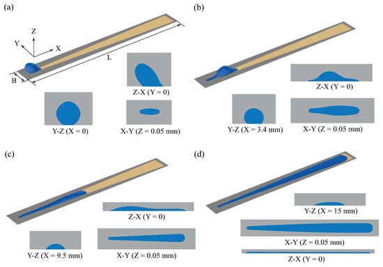
Figure 10.
Liquid motion on a wedge track laid on a superhydrophobic surface of length mm and width mm. (a–d) corresponds the isometric view and cross sectional views of the liquid at time s, s, s and 2 s respectively. Initial liquid deposition point is taken as the reference point (X, Y, Z) = (0, 0, 0).
4. Conclusions
Spray impact on a horizontal, wettability patterned surface was investigated. The wettability pattern consisted of 20 superhydrophilic wedge on a superhydrophobic background, and the wedges were placed on the surface in such a way that the narrower part of the wedge was towards the centre of the surface whereas the wider part of the wedge was towards the edge of the surface. During the spray impact, the droplets falling on the superhydrophilic wedge region turned to a film. The droplets falling on the superhydrophobic region either moved towards the wedge or jumped-off outside the surface. We identified different droplet transport modes from the superhydrophobic region to the superhydrophilic wedge and explored the physics. The droplets merged with the wedge’s liquid pool and moved towards the wider part of the wedge due to the Laplace pressure gradient between the wider and narrower part of the wedge. This passive movement of liquid on a wedge track was clarified using numerical simulation. The impacted droplets continuously drained out from the surface through the liquid pool in the wedge. The continuous replacement of liquid should have advantages in spray cooling and proposed wettability patterned surface can also be a better option for cooling a horizontal surface.
Supplementary Materials
The following are available online at https://www.mdpi.com/2227-9717/9/3/555/s1, Video S1—The phenomena of wrapping up a droplet by the liquid pool due to the crown splashing generated while the droplet falls near the boundary of the liquid pool; Video S2—The droplet transport mechanism from the superhydrophobic region to the superhydrophilic region due to the interaction of a falling droplet with stationary droplets presents on the superhydrophobic region; Video S3—The droplet transport mechanism from the superhydrophobic region to the superhydrophilic region due to the secondary droplet generated during splashing.
Author Contributions
Conceptualization, T.M.T., I.U.C., P.S.M. and M.K.T.; methodology, T.M.T., I.U.C. and P.S.M.; software, T.M.T., I.U.C. and K.D.; formal analysis, T.M.T., I.U.C., K.D. and P.S.M.; investigation, T.M.T. and I.U.C.; resources, T.M.T., I.U.C., K.D. and P.S.M.; data curation, T.M.T. and I.U.C.; writing–original draft preparation, T.M.T. and I.U.C.; writing—review and editing, T.M.T., I.U.C., K.D., P.S.M., A.P. and M.K.T.; visualization, T.M.T., I.U.C. and K.D.; supervision, T.M.T., I.U.C., K.D., P.S.M., A.P. and M.K.T.; project administration, P.S.M., A.P. and M.K.T.; funding acquisition, P.S.M., A.P. and M.K.T. All authors have read and agreed to the published version of the manuscript.
Funding
This research was funded by Scheme for Promotion of Academic and Research Collaboration (SPARC) program (Project: P644) from the Ministry of Human Resource Development, Government of India and the associated UKIERI support. The research is also funded by SERB-ECRA (Project No: ECR/2018/001806). M.K.T. also acknowledges support by the Wolfson Foundation and Royal Society for his Royal Society Wolfson Fellowship and the NICEDROPS project supported by the European Research Council (ERC) under the European Union’s Horizon 2020 research and innovation programme under grant agreement No. 714712.
Institutional Review Board Statement
Not applicable.
Informed Consent Statement
Not applicable.
Data Availability Statement
Not applicable.
Conflicts of Interest
The authors declare no conflict of interest. The funders had no role in the design of the study; in the collection, analyses, or interpretation of data; in the writing of the manuscript, or in the decision to publish the results.
Appendix A. Design of Wettability Pattern
To avoid the surface’s flooding issues during spray impact, the impacted droplets should be removed from the surface before it reaches the capillary length scale by multiple coalescences. The wedge dimension can be designed so that it can transport a drop of size lower than the capillary length scale. For a safe design, we considered the critical diameter of the droplet as ∼2 mm (∼4 μL), which needs to be passively transported through the wedge without flooding. We approximated the wedge length as half of the sample size (20 mm) to remove the droplets from the center through all the sides of the sample. The sharpest wedge may lead to the pinning of the droplet at the narrowest region. To ensure smooth liquid transport on the wedge, we maintained a width of L = 0.35 mm in the narrower section of the wedge. We performed the experiments at different wedge angles ( to ) on a 20 mm long wedge by placing a droplet of 4 μL volume at the narrower end of the wedge. We found that , the front position of the droplet, was not reached at the end of the wedge track. As there is a possibility of the droplet gets pinned in the narrower section of the wedge of smaller wedge angle. To avoid this problem, we selected the maximum possible wedge angle (), which could passively transport the droplet of diameter ∼2 mm.
We fabricated multiple designs with different spacing between wedges (c) and performed the spray impact experiment with the optimized wedge dimensions. Flooding was observed at the broader section of the wedges for c < 2 mm. As we need to maximise number of wedges on the surface for removing the maximum number of droplets, we chose c= 2 mm. With this value of c we could have 20 wedges on the surface.
Appendix B. Drop Size and Velocity
1-D PDPA system was used to simultaneously measure the droplet size d, μm and axial velocity u, m/s. Typically, 100,000 samples were collected with the data rate of more than 15,000 Hz. The statistical distribution of drop diameter (d) and axial velocity (u) of the impacted poly-dispersed spray are shown in Figure A1. The time taken to collect all the samples was less than 10 s. The drop size and velocity measurement validation were maintained above 90%.

Figure A1.
The statistical distribution of the droplet (a) diameter and (b) axial velocity of the impacted poly-dispersed spray from the 1D-PDPA measurement.
Appendix C. Numerical Modeling
Numerical modeling was performed in COMSOL Multiphysics [37] using laminar two-phase flow model and for capturing the interface, Phase field method [38] was used. The flow was assumed as laminar and incompressible. The density and viscosity of the droplet and the air phase were taken as constant. For the conservation of the mass, the continuity equation and, for the conservation of momentum, the Navier-Stokes equations were used as fluid flow governing equations.
Here, (kg/m3 is the average density of fluid, (Pa s) is the average viscosity of the fluid, p (Pa) denotes the fluid pressure, (m/s) is the fluid velocity. Surface tension force is represented by (N/m3), and is the identity matrix. The gravitational constant is . The average value of fluid density and viscosity is calculated as follows,
where and represents the density and dynamics viscosity of the droplet respectively whereas, and are the density and dynamics viscosity of air, respectively. and are the fraction of level set function which can be expressed as
where is the phase field function whose value varies from −1 to 1 across the interface. For air, the value of is −1 whereas the value of is 1 for the droplet. From Equations (A3) and (A4), in the droplet region, (), and () in the air region.
Cahn-Hilliard equation was used to describe the two-phase flow dynamics using diffused interface method. In this method, the diffused interface is tracked using a phase field function . The Cahn-Hilliard equation is of 4th order; to reduce the computational expenses the equation is solved with two 2nd order equation as follows,
Here, (m) is a thickness parameter of the transition layer which is taken as the half size of the typical mesh size . (N) is the mixing energy density which is related to the interfacial energy of the droplet as, . (m3 s/kg) is the mobility which determines the time scale of diffusion for the Cahn-Hilliard equation, and hence the governs the diffusion related time scale at the interface. The value of should be high enough to maintain a constant interface thickness, whereas it should be low enough to damp the convective motion. In COMSOL Multiphysics the mobility is determined by a mobility turning parameter . The mobility is calculated as . In the present case, the sensitivity of was studied and a suitable value of m s/kg was found. The external free energy is represented by f (J/m3). In the present case, the derivative of the external free energy is taken as 0. The surface tension force is calculated as,
Capillary number-based dynamic contact angle model was used to model the contact angle at the wetted wall [39]. The dynamic contact angle is calculated as follows
where represents the static contact angle at the wetted wall and r is the macroscopic length scale which is taken as the diameter of the droplet, and is the microscopic length scale which is taken as the slip length, 1 nm [39]. The average capillary number at the contact line is represented by , where is the average velocity of the droplet at the contact line. The contact line velocity is different at all the different points of the contact line. It is computationally expensive to consider the velocity information of all the contact points to calculate . In the present case, we have taken as the linear average of the contact line velocity at the front and back contact point of the droplet.
References
- Yarin, A.L. Drop impact dynamics: Splashing, spreading, receding, bouncing. Annu. Rev. Fluid Mech. 2006, 38, 159–192. [Google Scholar] [CrossRef]
- Josserand, C.; Thoroddsen, S.T. Drop impact on a solid surface. Annu. Rev. Fluid Mech. 2016, 48, 365–391. [Google Scholar] [CrossRef]
- Yu, X.; Zhang, Y.; Hu, R.; Luo, X. Water droplet bouncing dynamics. Nano Energy 2020, 81, 105647. [Google Scholar] [CrossRef]
- Kim, J. Spray cooling heat transfer: The state of the art. Int. J. Heat Fluid Flow 2007, 28, 753–767. [Google Scholar] [CrossRef]
- Antonini, C.; Amirfazli, A.; Marengo, M. Drop impact and wettability: From hydrophilic to superhydrophobic surfaces. Phys. Fluids 2012, 24, 102104. [Google Scholar] [CrossRef]
- Leng, L.J. Splash formation by spherical drops. J. Fluid Mech. 2001, 427, 73. [Google Scholar] [CrossRef]
- Burzynski, D.A.; Roisman, I.V.; Bansmer, S.E. On the splashing of high-speed drops impacting a dry surface. J. Fluid Mech. 2020, 892, A2. [Google Scholar] [CrossRef]
- Ramírez-Soto, O.; Sanjay, V.; Lohse, D.; Pham, J.T.; Vollmer, D. Lifting a sessile oil drop from a superamphiphobic surface with an impacting one. Sci. Adv. 2020, 6, eaba4330. [Google Scholar] [CrossRef]
- Lecointre, P.; Mouterde, T.; Checco, A.; Black, C.T.; Rahman, A.; Clanet, C.; Quéré, D. Ballistics of self-jumping microdroplets. Phys. Rev. Fluids 2019, 4, 013601. [Google Scholar] [CrossRef]
- Maitra, T.; Tiwari, M.K.; Antonini, C.; Schoch, P.; Jung, S.; Eberle, P.; Poulikakos, D. On the nanoengineering of superhydrophobic and impalement resistant surface textures below the freezing temperature. Nano Lett. 2014, 14, 172–182. [Google Scholar] [CrossRef]
- Lv, C.; Hao, P.; Zhang, X.; He, F. Drop impact upon superhydrophobic surfaces with regular and hierarchical roughness. Appl. Phys. Lett. 2016, 108, 141602. [Google Scholar] [CrossRef]
- De Gennes, P.G.; Brochard-Wyart, F.; Quéré, D. Capillarity and Wetting Phenomena: Drops, Bubbles, Pearls, Waves; Springer Science & Business Media: Berlin/Heidelberg, Germany, 2013. [Google Scholar]
- Grissom, W.M.; Wierum, F. Liquid spray cooling of a heated surface. Int. J. Heat Mass Transf. 1981, 24, 261–271. [Google Scholar] [CrossRef]
- Jowkar, S.; Morad, M. Rebounding suppression of droplet impact on hot surfaces: Effect of surface temperature and concaveness. Soft Matter 2019, 15, 1017–1026. [Google Scholar] [CrossRef] [PubMed]
- Salman, A.S.; Abdulrazzaq, N.M.; Tikadar, A.; Oudah, S.K.; Khan, J.A. Parametric study of heat transfer characteristics of enhanced surfaces in a spray cooling system: An experimental investigation. Appl. Therm. Eng. 2021, 183, 115824. [Google Scholar] [CrossRef]
- Xu, R.N.; Cao, L.; Wang, G.Y.; Chen, J.N.; Jiang, P.X. Experimental investigation of closed loop spray cooling with micro-and hybrid micro-/nano-engineered surfaces. Appl. Therm. Eng. 2020, 180, 115697. [Google Scholar] [CrossRef]
- Ghosh, A.; Beaini, S.; Zhang, B.J.; Ganguly, R.; Megaridis, C.M. Enhancing dropwise condensation through bioinspired wettability patterning. Langmuir 2014, 30, 13103–13115. [Google Scholar] [CrossRef]
- Mahapatra, P.S.; Ghosh, A.; Ganguly, R.; Megaridis, C.M. Key design and operating parameters for enhancing dropwise condensation through wettability patterning. Int. J. Heat Mass Transf. 2016, 92, 877–883. [Google Scholar] [CrossRef]
- Betz, A.R.; Jenkins, J.; Attinger, D. Boiling heat transfer on superhydrophilic, superhydrophobic, and superbiphilic surfaces. Int. J. Heat Mass Transf. 2013, 57, 733–741. [Google Scholar] [CrossRef]
- Feng, J.; Zhong, L.; Guo, Z. Sprayed hieratical biomimetic superhydrophilic-superhydrophobic surface for efficient fog harvesting. Chem. Eng. J. 2020, 388, 124283. [Google Scholar] [CrossRef]
- Schutzius, T.M.; Elsharkawy, M.; Tiwari, M.K.; Megaridis, C.M. Surface tension confined (STC) tracks for capillary-driven transport of low surface tension liquids. Lab Chip 2012, 12, 5237–5242. [Google Scholar] [CrossRef] [PubMed]
- Sen, U.; Chatterjee, S.; Ganguly, R.; Dodge, R.; Yu, L.; Megaridis, C.M. Scaling laws in directional spreading of droplets on wettability-confined diverging tracks. Langmuir 2018, 34, 1899–1907. [Google Scholar] [CrossRef]
- Chatterjee, S.; Sinha Mahapatra, P.; Ibrahim, A.; Ganguly, R.; Yu, L.; Dodge, R.; Megaridis, C.M. Precise liquid transport on and through thin porous materials. Langmuir 2018, 34, 2865–2875. [Google Scholar] [CrossRef]
- Morrissette, J.M.; Mahapatra, P.S.; Ghosh, A.; Ganguly, R.; Megaridis, C.M. Rapid, self-driven liquid mixing on open-surface microfluidic platforms. Sci. Rep. 2017, 7, 1–13. [Google Scholar] [CrossRef] [PubMed]
- Chowdhury, I.U.; Mahapatra, P.S.; Sen, A.K. Shape evolution of drops on surfaces of different wettability gradients. Chem. Eng. Sci. 2020, 229, 116136. [Google Scholar] [CrossRef]
- Li, J.; Zhou, X.; Li, J.; Che, L.; Yao, J.; McHale, G.; Chaudhury, M.K.; Wang, Z. Topological liquid diode. Sci. Adv. 2017, 3, eaao3530. [Google Scholar] [CrossRef]
- Schutzius, T.M.; Graeber, G.; Elsharkawy, M.; Oreluk, J.; Megaridis, C.M. Morphing and vectoring impacting droplets by means of wettability-engineered surfaces. Sci. Rep. 2014, 4, 7029. [Google Scholar] [CrossRef] [PubMed]
- Qi, W.; Weisensee, P.B. Dynamic wetting and heat transfer during droplet impact on bi-phobic wettability-patterned surfaces. Phys. Fluids 2020, 32, 067110. [Google Scholar] [CrossRef]
- Koukoravas, T.P.; Ghosh, A.; Mahapatra, P.S.; Ganguly, R.; Megaridis, C.M. Spatially-selective cooling by liquid jet impinging orthogonally on a wettability-patterned surface. Int. J. Heat Mass Transf. 2016, 95, 142–152. [Google Scholar] [CrossRef]
- Dhivyaraja, K.; Gaddes, D.; Freeman, E.; Tadigadapa, S.; Panchagnula, M. Dynamical similarity and universality of drop size and velocity spectra in sprays. J. Fluid Mech. 2019, 860, 510–543. [Google Scholar] [CrossRef]
- Quetzeri-Santiago, M.A.; Yokoi, K.; Castrejón-Pita, A.A.; Castrejón-Pita, J.R. Role of the dynamic contact angle on splashing. Phys. Rev. Lett. 2019, 122, 228001. [Google Scholar] [CrossRef]
- Quetzeri-Santiago, M.A.; Castrejón-Pita, A.A.; Castrejón-Pita, J.R. The effect of surface roughness on the contact line and splashing dynamics of impacting droplets. Sci. Rep. 2019, 9, 1–10. [Google Scholar] [CrossRef] [PubMed]
- Milne, A.; Amirfazli, A. Drop shedding by shear flow for hydrophilic to superhydrophobic surfaces. Langmuir 2009, 25, 14155–14164. [Google Scholar] [CrossRef] [PubMed]
- Moghtadernejad, S.; Jadidi, M.; Ahmmed, K.T.; Lee, C.; Dolatabadi, A.; Kietzig, A.M. Experimental study of droplet shedding on laser-patterned substrates. Phys. Fluids 2019, 31, 122107. [Google Scholar] [CrossRef]
- Boreyko, J.B.; Chen, C.H. Self-propelled dropwise condensate on superhydrophobic surfaces. Phys. Rev. Lett. 2009, 103, 184501. [Google Scholar] [CrossRef] [PubMed]
- Ghosh, A.; Ganguly, R.; Schutzius, T.M.; Megaridis, C.M. Wettability patterning for high-rate, pumpless fluid transport on open, non-planar microfluidic platforms. Lab Chip 2014, 14, 1538–1550. [Google Scholar] [CrossRef] [PubMed]
- Multiphysics, C. COMSOL Multiphysics CFD Module User Guide, version 5.3a; COMSOL: Stockholm, Sweden, 2015; pp. 208–265. [Google Scholar]
- Cai, X.; Marschall, H.; Wörner, M.; Deutschmann, O. Numerical simulation of wetting phenomena with a phase-field method using OpenFOAM®. Chem. Eng. Technol. 2015, 38, 1985–1992. [Google Scholar] [CrossRef]
- Dupont, J.B.; Legendre, D. Numerical simulation of static and sliding drop with contact angle hysteresis. J. Comput. Phys. 2010, 229, 2453–2478. [Google Scholar] [CrossRef]
Publisher’s Note: MDPI stays neutral with regard to jurisdictional claims in published maps and institutional affiliations. |
© 2021 by the authors. Licensee MDPI, Basel, Switzerland. This article is an open access article distributed under the terms and conditions of the Creative Commons Attribution (CC BY) license (http://creativecommons.org/licenses/by/4.0/).