Article

Research on Local Heating Regeneration Method for Air-Conditioning Systems

College of Energy and Power Engineering, Nanjing University of Science and Technology, Nanjing 210094, China
*
Author to whom correspondence should be addressed.
Processes 2021, 9(3), 444; https://doi.org/10.3390/pr9030444
Submission received: 8 February 2021 / Revised: 23 February 2021 / Accepted: 24 February 2021 / Published: 1 March 2021

Abstract

:
Absorption air-conditioning systems have a great advantage in terms of energy conservation and environmental protection. However, the large amount of energy waste in the thermal regeneration process leads to lower efficiency and impedes its development. To reduce energy loss and improve performance, a local heating regeneration method is proposed in this paper. The main principle is reducing the volume of the liquid participating regeneration. Including the solar steam mode, two modes are introduced and configured. Theoretical and experimental research has been made on the new methods. Models have been developed for comparison analysis. Experiments have been conducted on water and absorbent solution with different modes. Performance has been evaluated based on the experimental data. The results expose the influence of different parameters, like liquid volume and solution concentration, on the regeneration process. The local heating method improved the regeneration efficiency by 40% in the no solar steam mode and the performance tripled in the solar steam mode. The COP (the ratio of cooling load to energy consumption) of the absorption system with the solar steam mode is more than two times of that with the traditional regeneration mode. It shows the local heating regeneration method has good potential in future application.

1. Introduction

Avoiding the combustion of fossil fuels, the application of renewable energy may hold the key to a sustainable society [1]. It is especially urgent for today’s buildings, which consume more than 30% energy of the total supply [2]. An air-conditioning system is one major energy consumer in buildings with the wide used vapor compression system taking up one third of the power. The development of renewable energy driven air-conditioning systems comes is a hot research topic in recent years. Liu et al. investigated the optimal operation of buildings with solar driven systems [3]. Al-Nimr et al. proposed a solar hybrid system for higher efficiency [4]. Nader et al. made an assessment of the existing photovoltaic air conditioning system [5]. The solar energy driven system is a promising one among them [6]. Much research has been done in recent years. Hamrahi et al. did an experimental study of the performance of a continues solar adsorption chiller using nano-activated carbon/methanol as a working pair [7]. Afanasyeva et al. studied the relevance of photovoltaic (PV) with single-axis tracking for energy scenarios [8]. Awad et al. proposed a load-match-driven design of solar PV systems at high latitudes in the Northern hemisphere and investigated its impact on the grid [9]. Eidan et al. studied the performance improvement of a heat pipe-evacuated tube solar collector using Al2O3 and CuO/acetone nanofluids [10]. Solar illumination can be converted into electric power or thermal heat, both capable of driving air-conditioning systems. Many researchers prefer the heat driven system, as the performance of the electric power driven system is limited by the relatively low PV efficiency.
Absorption and adsorption systems are two major types of the air-conditioning system that can be driven by solar heat. Jain et al. have made comparative performance study and advanced exergy analysis of a novel vapor compression–absorption integrated refrigeration system [11]. Shirazi et al. reviewed the development of the solar-powered absorption chillers [12]. Mahmoudi et al. proposed a new flexible geothermal based cogeneration system producing power and refrigeration [13]. Wang et al. made the performance comparative study of a solar-powered adsorption refrigerator with a CPC collector/adsorbent bed [14]. Wang et al. did an experimental study on the effect of enhanced mass transfer on the performance improvement of a solar-driven adsorption refrigeration system [15]. Those systems are possible alternatives to the vapor compression system, not only because they are driven by renewable energy but also because their refrigerants are more environmentally friendly. This is especially true for the absorption system (including the liquid desiccant cooling system). With good cycle continuity and energy storage characteristic, the absorption system is more mature in many aspects. However, its development is impeded by the lower performance compared to the vapor compression system. The major reason for this is due to the energy waste in the regeneration process, through which the absorbent concentrates and forms the cycle. If the regeneration efficiency improves, the system performance will also improve. Many efforts have been made in this area. Most of them are about the combined systems that improve integral performance. Dai et al. [16] did an experimental investigation on a GAX (Generator Absorber heat eXchanger) based absorption heat pump driven by hybrid liquefied petroleum gas and solar energy. Patel et al. [17] proposed a solar-biomass driven combined vapor compression–absorption system. A combined system can also be built with natural energy resources. Ezzat et al. [18] studied a geothermal-solar energy based system. Energy storage is also a good measure. Fan et al. [19] investigated the heat storage method for the solar energy driven LiBr air-conditioning system. To further enhance the storage capacity, El-Shaarawi et al. [20] analyzed a solar driven dual storage absorption system. For the solar heat driven system, the enhancement of the solar energy utilization efficiency is an effective way to improve the whole performance. Siavashi et al. [21] studied the nanofluid-based direct absorption solar collector. Kumar et al. [22] predicted the performance of an extended surface solar air collector with twisted tape inserts. Rodríguez-Sánchez et al. [23] developed a thermo-mechanical model of a solar central receiver.
Though progresses has been made, there is room to explore by solving the energy waste problem. In regeneration, input energy is not only used to generate water vapor out of absorbent (or desiccant) solution; it is also used to first heat the solution body. This leads to energy waste in three ways: first, it wastes energy in generating a hot solution, which is a useless by-product of the process. It wastes even more energy with larger solution volume. Second, energy dissipates to the environment during the heating process. Bigger solution body and higher temperature could increase energy loss in this way. Third, the left hot solution bulk body is a burden after regeneration. High solution temperature is not favorable for the absorption (or dehumidification) process. It may need additional cooling measures, which demands more energy. This restricts the regeneration efficiency and harms performance. Therefore, an effective way for efficiency improvement is to reduce the volume of hot solution so that less energy will be consumed heating the solution bulk body. As solution temperature should be maintained to ensure regeneration performance, a possible method is to make the solution body take part in regeneration as little as possible. In an ideal state, the water in the solution participating in regeneration is just equal to that set to evaporate. For the same amount of water, the latent heat change of evaporation is much larger than the sensible heat change. The energy is almost consumed to generate water vapor with very little waste. Also, the energy loss from heat dissipation is less for a smaller body solution. A practical situation would be to have a small part of the solution body locally heated to evaporate the water instead of heating up the whole solution body. Through this local heating method, energy will be saved, and the performance improved.
Few researchers have tested this idea. Chen et al. [24] propose the conception of the solar steam mode, which shows the advantage of heat localization in bettering the efficiency of energy utilization. They reported the development of a new approach and corresponding material structure that localizes the solar energy where evaporation occurs and minimizes the heat losses leading to enhanced solar thermal efficiency at low optical concentration in open air while generating steam. Under solar illumination, the developed structure forms a hot spot internally where evaporation occurs. The fluid wicks to the hot spot, evaporates and forms vapor. This structure has four main characteristics: high absorption in the solar spectrum, low thermal conductivity to suppress thermal conduction away from the hot internal region, hydrophilic surfaces to leverage capillary forces and promote fluid flow to the hot region, and interconnected pores for fluid flow to and from the structure. They have achieved solar thermal efficiency up to 85% at the illumination power of 10 kW/m2. This work is attracting more researchers to explore the potential of the solar steam mode. Kaur et al. have an all-ceramic micro fibrous solar steam generator [25]. Yang et al. investigated the functionalized graphene for highly efficient solar thermal steam generation [26]. Yin et al. studied the extremely black vertically aligned carbon nanotube arrays for solar steam generation [27]. Jia et al. studied the rich mesostructures derived from natural woods for solar steam generation [28]. Most of them concentrate on the synthesis method and physical or chemical properties of different materials.
Though the solar steam mode is promising for a wide range of industrial applications, like desalination and air-conditioning, few efforts have yet been made in this area. The present works have only conducted experiments on pure water, while it evaporates saline solution in a real situation. It is necessary to investigate the real performance of the solar steam mode for practical application. To improve the efficiency of the absorption air-conditioning system, this paper presents the progresses of testing the local heating method from three points. First, both theoretical and experimental analysis were made to expose the advantage of evaporating an absorbent solution of a smaller body volume. Second, the performance of the solar steam mode was investigated experimentally with a common absorbent, the LiCl solution, as the liquid subject. This shows the impact of the solar steam mode on the regeneration process of the absorption system. Third, the air-conditioning system performance was evaluated with different local heating regeneration modes. The results indicate local heating modes improve the system COP (the ration of cooling load to energy consumption) and the solar steam mode does even better. This idea could potentially be used in future applications.

2. Material and Method

2.1. Regeneration of Smaller Solution Body for Absorption System

Figure 1 presents the flow chart of a typical absorption air-conditioning system driven by solar energy. The solar thermal collector provides the energy concentering the weak solution leaving the absorber. In Figure 1, the solution first enters into the solar thermal collector and raises its temperature, and then it evaporates in the generator. In other system designs [2], the solution may directly enter into the generator and remain a hot medium (like water) as the solar thermal collector heats it up. All of these systems are heating the whole solution body to a certain temperature and then obtaining strong solution and water at the same time. This wastes energy in acquiring the extra hot solution. With a valve and branch pipe (red line), an improved configuration is achieved by reducing the solution to be heated in the generator. The weak solution leaving the absorber divides into two streams: one goes into the generator for evaporation; the other one mixes with the strong solution regenerated from the generator and returns to the absorber. The amount of evaporated water does not change in this new sketch. It reduces the solution body in the generator by regulating the valve. Theoretically, the smaller volume of the stream goes into the generator, the less energy is wasted and more efficiency can be obtained. It can be seen as a local heating mode as only small part of the solution is heated. The solar steam mode realizes heating localization in a different way.

2.2. Solar Steam Mode

Solar-enabled steam generation is considered one of the most promising solar-energy-harvesting technologies. Chen et al. first took a new absorber design with heat localization, in which heat is confined at the evaporation surface and heat loss from the heating spot to the bulk water is minimized. Thus, such an absorber can induce high solar thermal efficiency and produce high-temperature vapor under the same solar intensity. The solar steam mode is presented in Figure 2a,b. Figure 2a shows the working process, where an object floats on water, and vapor is generated under the sun. The floating object is the core part of the solar steam mode. Its structure and working principle are presented in Figure 2b. The material for solar steam mode usually has a double-layer structure, e.g., a carbon foam layer supporting an exfoliated graphite layer. The bottom layer is thermally insulated with smaller pore size for liquid supply. It adopts the material with low thermo conductivity and lets the solution permeate under capillary force. The upper layer has larger pore size so vapor can escape, and its material has high absorption in the solar spectrum. It forms a chamber where only small volume solution is heated and evaporated. The bottom part controls the size of the heating solution body and reduces the energy loss in dissipating. The upper part propels the absorption of the solar energy as high as possible. Thus, the general system efficiency is improved. Solar steam mode has attracted many researchers’ attention and comes to be a hot spot in related areas. Yet only pure water has been taken as the liquid for testing, and most work focuses on the materials while few care about practical performance. In this paper, we test the regeneration of liquid absorbent with the solar steam mode and make an analysis on this method.

2.3. Experimental System

Experiments have been conducted to investigate the idea of a heating localization method. It includes two major parts. In the first part, we tested the performance of regenerating smaller liquid body and try to find out whether it will be more efficient in this situation. Both pure water and absorbent solution were chosen as the subjects. In the second part, the regeneration performance was investigated for the solar steam mode. As similar works have been done with pure water, we mainly research the case of absorbent solution.
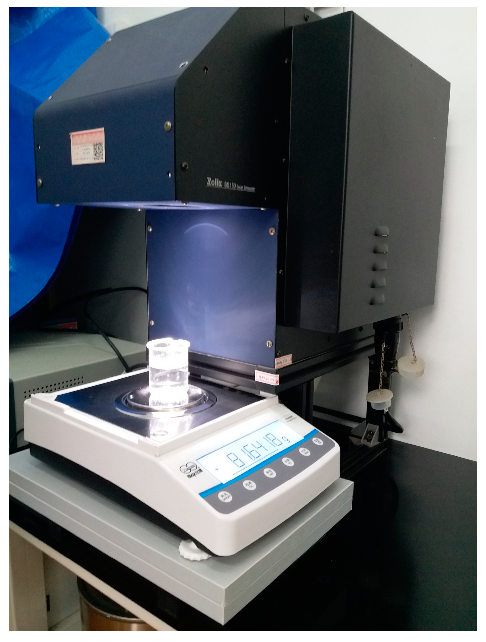
The experimental system of the first part is presented in Figure 3. It consists of a solar simulator and an electronic balance, which has a liquid beaker on it. The liquid beaker acts as experiment subject. In the experiments, the solar simulator constantly provided the solar illumination maintained at 1 kW/m2 by controlling the input current at 8.5 A. The electronic balance measured the mass change of the liquid and beaker, or the evaporating rate. The type of simulator was SS150A. The stability of the light source was below 0.5%, the uniformity was below 2% and the maximum illumination was 1.2 kW/m2. The type of the electronic balance was FA1004. Its accuracy was ±0.1 mg and the measurement ranged from 0–100 g. The temperature was measured by Pt100 resistance temperature detectors (RTDs) with an accuracy of ±0.1 °C.
The system performance can be expressed as:
C O P = Q 0 G = l m e G .
The uncertainty σCOP of the measured COP can be calculated as the function of σme and σG:
σ C O P = ( l m e G ) m e σ m e + ( l m e G ) G σ G = ( l G ) σ m e + ( l m e G 2 ) σ G ;
σ C O P C O P = ( l G ) σ m e + ( l m e G 2 ) σ G l m e G = σ m e l m e σ G G .
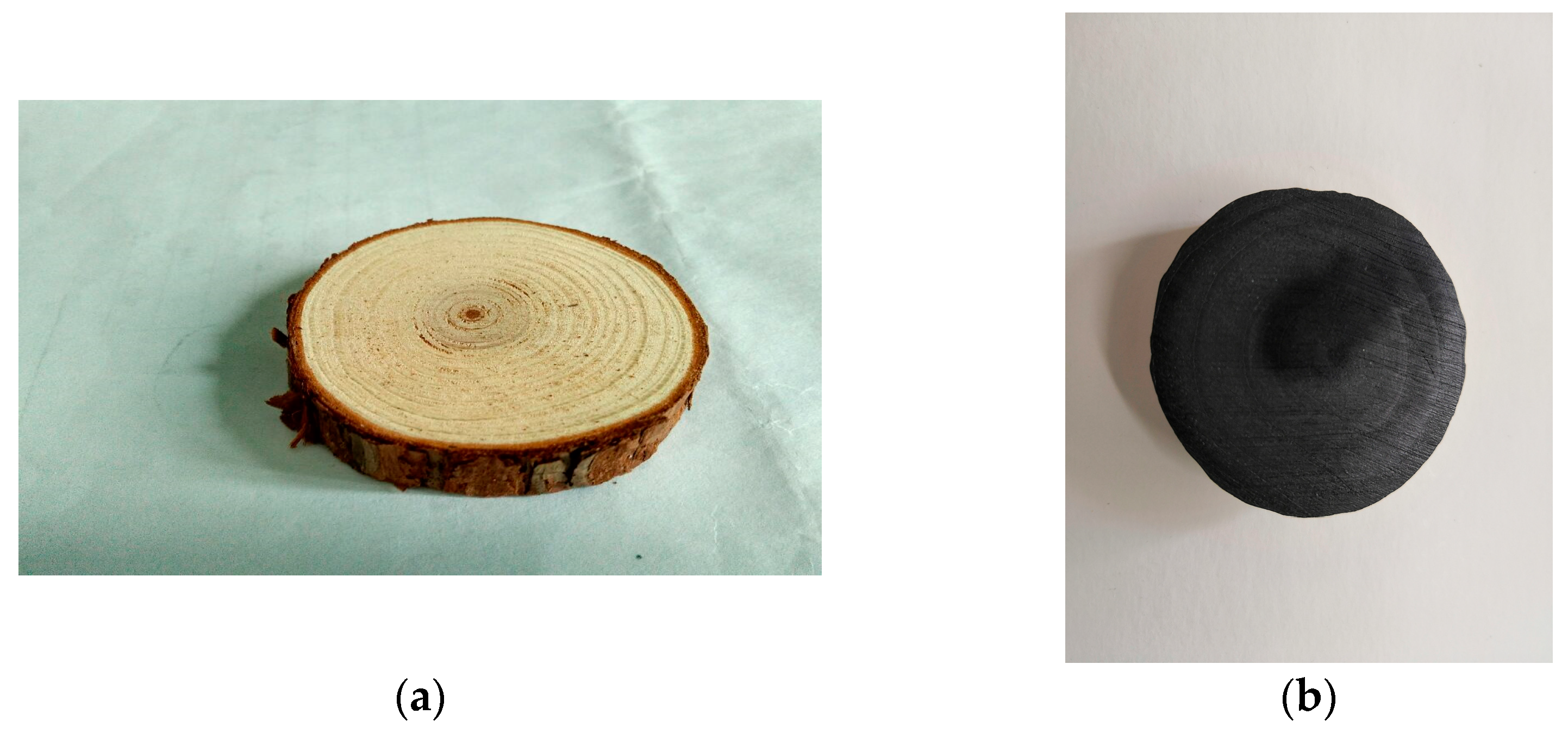
The material for testing the solar steam mode was prepared. Most materials in the references are either expensive or technically demanding for large-scale expansion. Considering low cost, operability, and stability is critical to practical application Therefore we chose the high temperature treated wood [29] in our experiments. The preparation process was according to the reference fir wood blocks (Wanqing Co., Ltd., 95%) with a diameter of 5 cm (Figure 4a). It was treated with a high temperature fritting furnace (furnace type KSL-1100X-S) and the highest temperature was 1100°C. The temperature rising rate was set as 10 °C/minute. When the temperature reached 250 °C, it stopped rising and remained steady for about 15 min. The treated wood was shown in Figure 4b. Its diameter is about 4 cm by cutting the edge.

2.4. Theoretical Analysis of the Performance with the Local Heating Method

Both the methods introduced above present the idea of local heating, which is believed to improve efficiency by reducing energy loss. Here the preliminary analysis will be given based on energy balance equations. In the regeneration (evaporation) process, the input energy will be equal to the sum of the system enthalpy change and the total energy loss:
Q i = ( H 2 H 1 ) + Q l ,
where Qi is the input energy; H1, H2 are the system enthalpy before and after regeneration, respectively; and Ql is the energy loss. H1 is the enthalpy of the solution entering the regenerator while H2 consists of the enthalpy of the regenerated solution and the evaporated water vapour:
Q i = [ ( m w l + c p w m w t w ) + c p s 2 m s 2 t s 2 ] c p s 1 m s 1 t s 1 + Q l ,
where mw is the amount of evaporated water vapor; ms1 and ms2 are the solution mass before and after regeneration, respectively; l is latent heat of water vaporization; cpw, cps1 and cps2 are the specific heat of the water vapor, the solution before regeneration and the solution after regeneration, respectively; tw, ts1 and tps2 are the temperature of the water vapor, the solution before regeneration and the solution after regeneration, respectively. Normally, the item cpwmwtw is much smaller than the item mwl as l is always larger than cpwtw; cpwmwtw is also considered much smaller than cps1ms1ts1 and cps2ms2ts2, because the amount of evaporated water is very small compared with that of the solution body. Therefore, this item can be neglected to simplify the analysis. With the same reason, we can also assume ms2 is equal to ms1, since mw is the only difference between them. Equation (5) can be written as:
Q i m w l + m s 1 ( c p s 2 t s 2 c p s 1 t s 1 ) + Q l .
Mass balance equation reveals the relationship between mw and ms:
m s 1 C o n i r = ( m s 1 m w ) C o n o r ,
where Conir is the concentration of the solution entering the regenerator; and Conor is the concentration of the solution leaving the regenerator. Therefore:
m s 1 = m w ( C o n o r C o n o r C o n i r ) .
Combine Equations (6) and (8):
Q i m w [ l + ( C o n o r C o n o r C o n i r ) ( c p s 2 t s 2 c p s 1 t s 1 ) ] + Q l .
Assume the cooling capacity of the absorption system is Q0:
Q 0 = m w l .
The coefficient of performance of the absorption system would be:
C O P = Q 0 Q i m w l m w [ l + ( C o n o r C o n o r C o n i r ) ( c p s 2 t s 2 c p s 1 t s 1 ) ] + Q l = l [ l + ( 1 1 C o n i r C o n o r ) ( c p s 2 t s 2 c p s 1 t s 1 ) ] + Q l m w .
Equation (11) shows the COP of the absorption system is below 1 (without adopting the waste heat reutilization method) and will be influenced by different parameters. It decreases with smaller concentration changes before and after regeneration, higher rising solution temperature, less evaporated water vapor and more energy loss during the process. If the solar thermal conversion efficiency is taken into account, the COP is (assume the efficiency is ζ):
C O P = l ζ [ l + ( 1 1 C o n i r C o n o r ) ( c p s 2 t s 2 c p s 1 t s 1 ) ] + Q l m w .
For the heating localization idea, Equation (5) shows less solution participating in regeneration leads to smaller Qi, and thus improves the performance. An ideal situation is the solution in regeneration is so small that it completely evaporates and turns to water vapor and the solid absorbent salt. In this case, ms1 is as small as mw and the related enthalpy items can be neglected. Equation (5) is rewritten as:
Q i m w l + Q l .
Equation (12) is expressed as:
C O P = l ζ l + Q l m w .
With these equations, comparison analysis can be made between the normal method and the heating localization method.

3. Results and Discussion

3.1. Experimental Results of the Heating Localization Idea (Not in the Solar Steam Mode)

The environment temperature was maintained around 27 °C and the humidity ratio was around 42%. The initial liquid temperature was about 25 °C. To test the heating localization idea, we mainly investigated the evaporation rate with different liquid volumes. The mass of the beaker and liquid was recorded every ten seconds, and the whole process lasted for one hour. The mass change was taken as the evaporation rate under different working conditions. The first group of the experiments were conducted on pure water. Figure 5 shows the mass of the beaker and water with three different water volumes: 5 mL, 20 mL and 30 mL. The points standing for the evaporation rates overlap in the figure, which means they are almost equal. The three lines go in the similar tendency, indicating there is no big change of evaporation rate with different water volumes. The average rates were 0.000873 g/10 s, 0.000923 g/10 s and 0.000859 g/10 s with the water volume 5 mL, 20 mL and 30 mL, respectively. The predicted higher rate with smaller volume did not come true in the experiments. The liquid with smaller volume surely reduces the energy loss to the environment, but this did not count much in the final results. The reason may be because this set of the experiments reflected the local heating idea for all three volumes at the very beginning. In the traditional system, the liquid to be regenerated is first completely heated to a certain temperature and then goes through the regeneration process. It was different in the experiments, as all three situations can be considered as the local heating mode, which started from the liquid surface. This group of experiments actually expose the performance of the local heating mode as having little influence from the total volume of the liquid body.
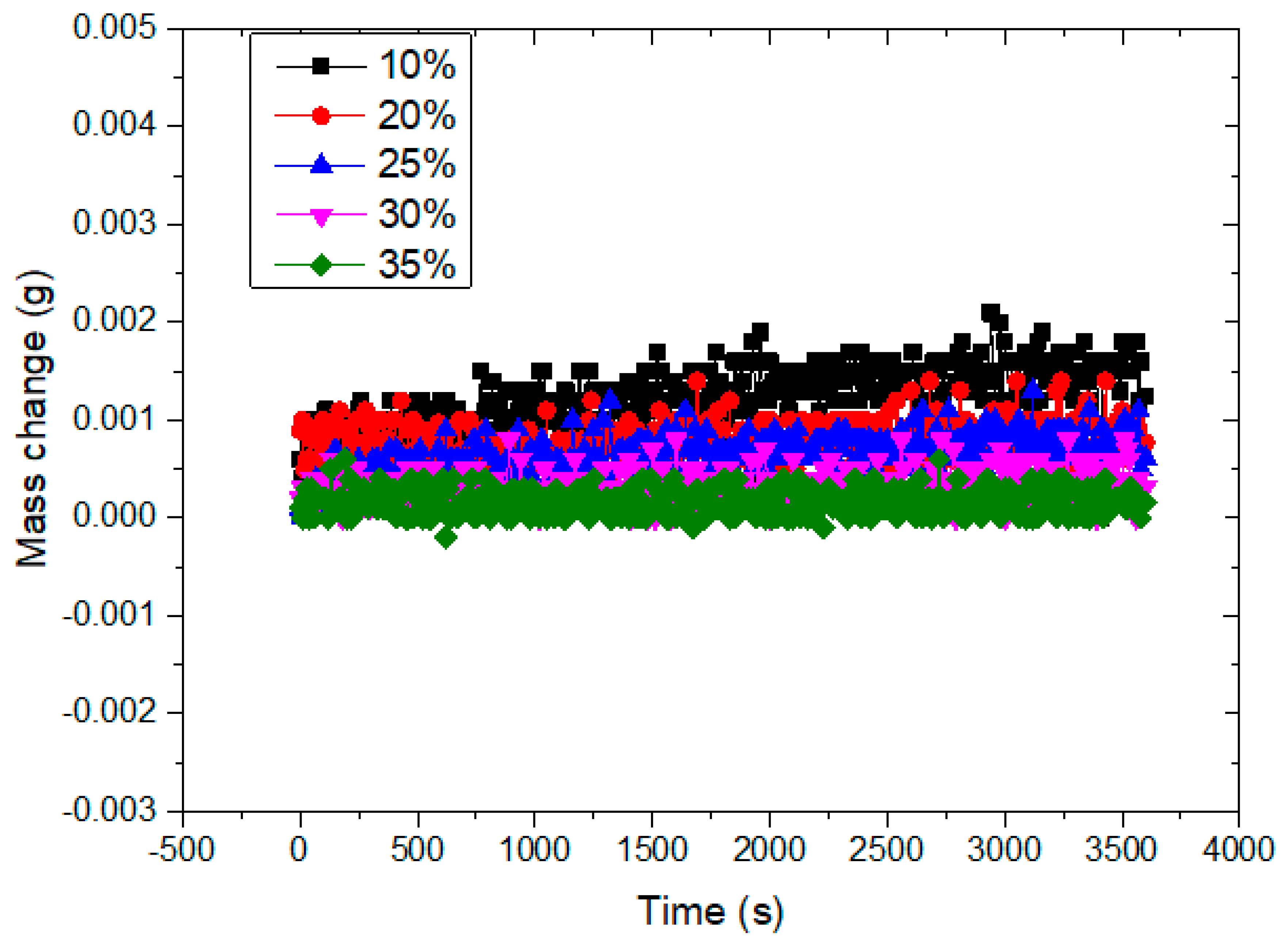
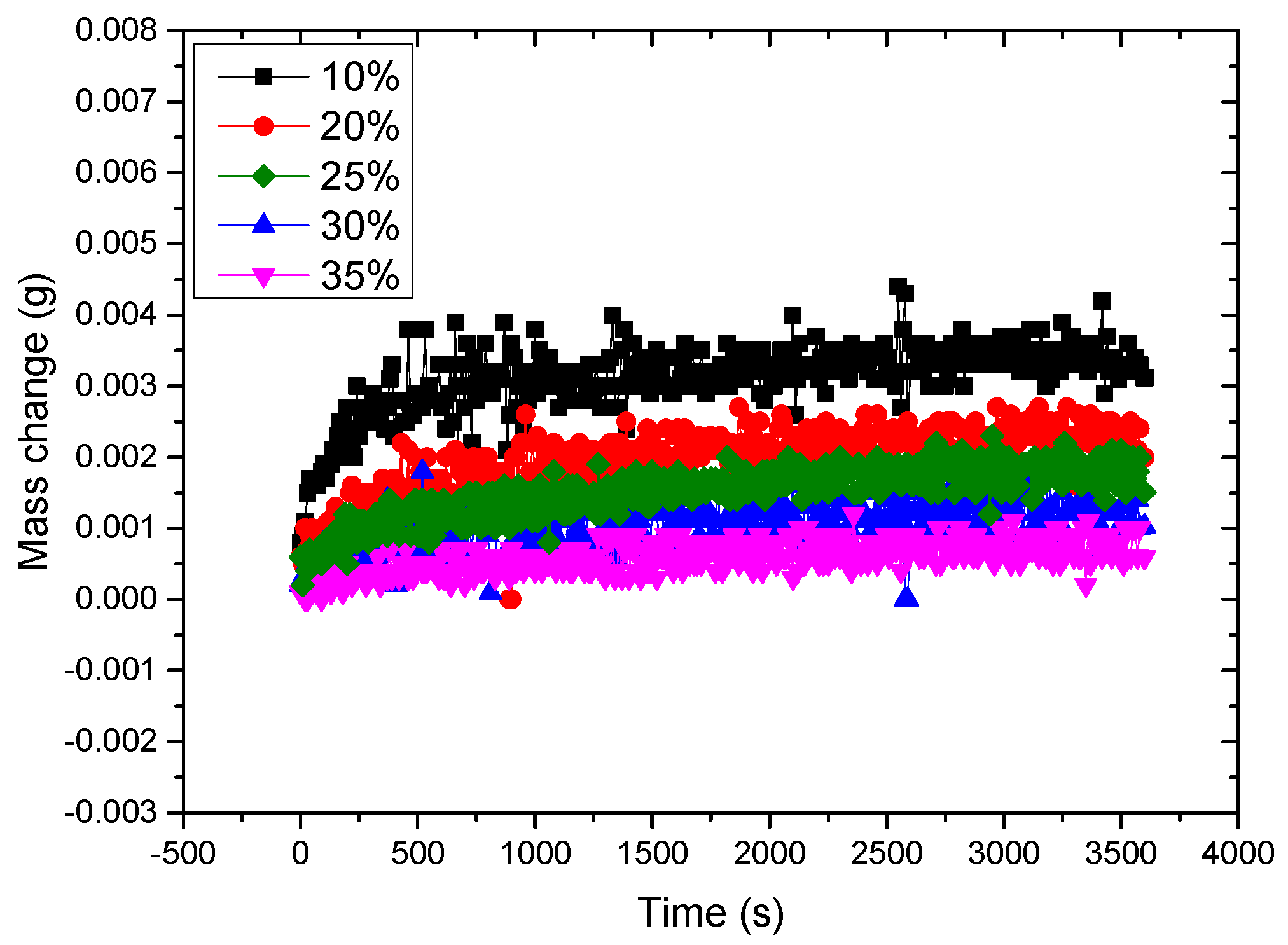
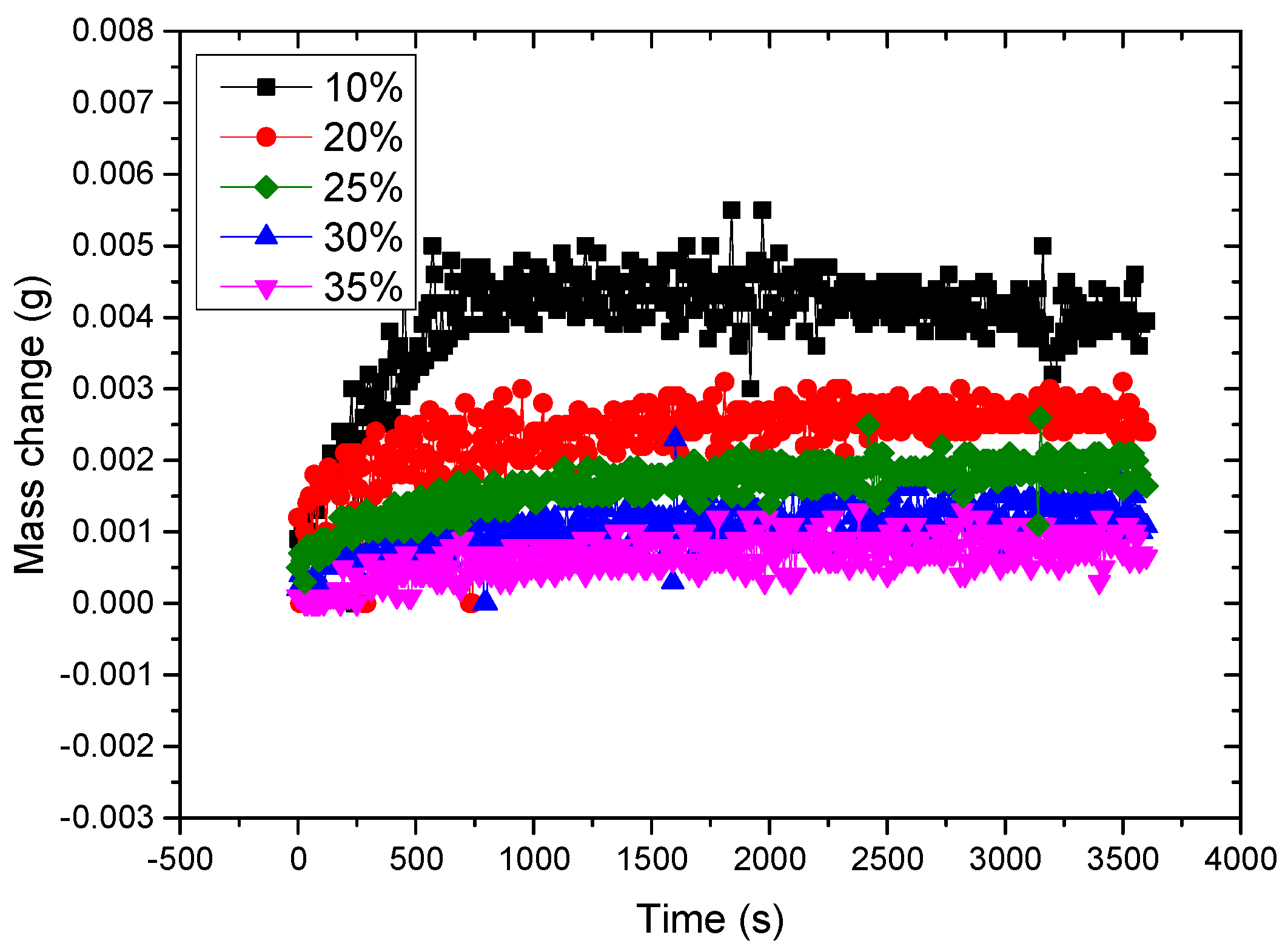
If the liquid is changed from pure water to an absorbent solution, the same conclusion can be attained. Take LiCl solution as the absorbent. Two groups of experiments have been made with different solution volumes. The results of 20 mL and 30 mL are respectively presented in Figure 6 and Figure 7. Five different mass concentrations have been selected. Both Figure 6 and Figure 7 show the mass change (or the evaporation rate) is bigger with smaller concentrations, this is in accordance with the fact it is harder to evaporate water from a stronger solution. The reason is that when the solution becomes stronger, it enlarges its capability of absorbing water vapor, and thus impedes the evaporation process. The average rates in Figure 6 were 0.001233 g/10 s, 0.000744 g/10 s, 0.00065 g/10 s, 0.000421 g/10 s and 0.000213 g/10 s corresponding to five concentrations. The average rates in Figure 7 were 0.001244 g/10 s, 0.000772 g/10 s, 0.000615 g/10 s, 0.000317 g/10 s, 0.000165 g/10 s corresponding to five concentrations. For the solution, the liquid volume also hardly influences the evaporating performance in the same surface local heating mode.

3.2. Experimental Results of the Localization Heating (in the Solar Steam Mode)

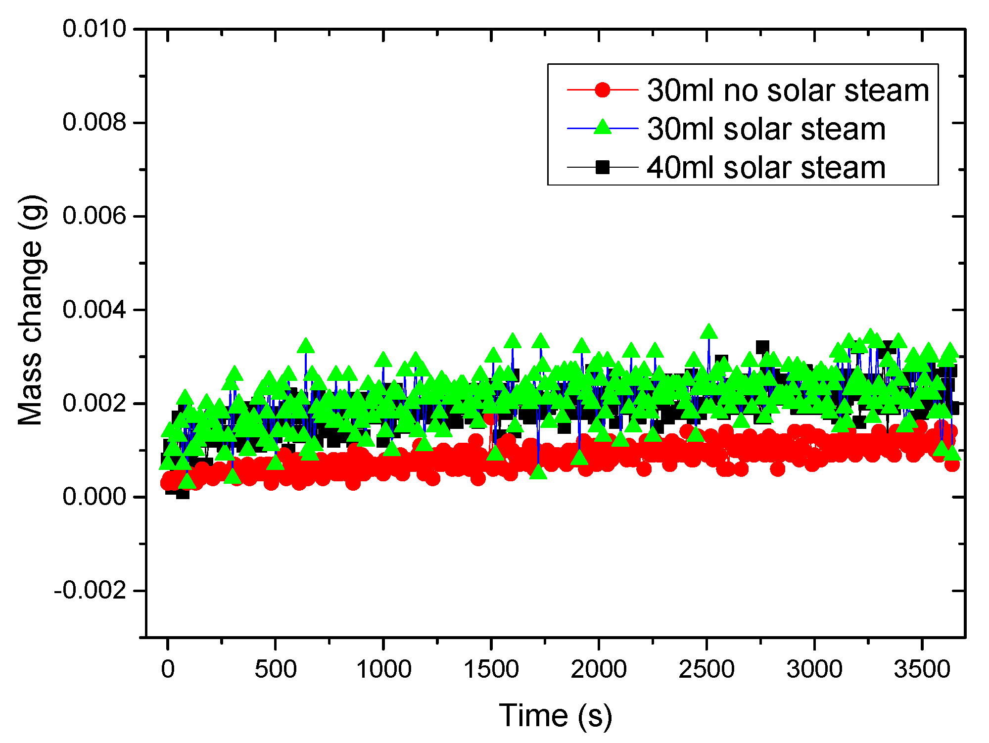
Experiments were also done on the performance of local heating with the material of solar steam structure. All the working conditions were the same as in Section 3.1 except the prepared wood material was adopted (Figure 8). The first group of experiments were carried out with pure water with different volumes. The results are presented in Figure 9. In the solar steam mode, the mass changes are almost equal with the volumes of 30 mL and 40 mL, so the volume change had little influence on the evaporation rate. Compared with the water evaporating without the solar steam material, the situation with the material had a big rise in evaporation rate. The average value was 0.002101 g/10 s for the 30 mL situation with the solar steam material, compared to 0.000859 g/10 s without the material. About 2.5 times the rate was achieved. The evaporation rate was so high that the "steam" phenomenon (Figure 10) can be seen after 20 min, which has never happened in the situation without the solar steam structure material. The thermal conductivity of the water was 0.599 Wm−1K−1 at 20 °C, for dry wood it was 0.33 Wm−1K−1 and for wet wood it was 0.54 Wm−1K−1. The floating wood with the solar steam structure does not have much priority in thermal insulation. Therefore, the real reason for improvement is not the bottom of the layer but could lie in the characteristic of the upper layer. For one thing, the upper structure improves the utilization of the solar energy as claimed in the references. Secondly, we believe the multi-pore structure of the treated wood played a key role in this process. The pores split the original intact liquid surface and thus similarly create numerous micro cells filled with liquid. It’s like separating the big surface to many small pieces, which facilitates the evaporation process. The solar steam structure not only reflects the heat localization idea in the vertical direction, but more importantly also reflects in the lateral direction of the surface.
We then changed the liquid from pure water to absorbent solution and used LiCl solution as the absorbent. Two groups of experiments were done with different solution volumes. The results of 20 mL and 30 mL are presented in Figure 11 and Figure 12, respectively. Five different mass concentrations were selected. Figure 11 and Figure 12 show the evaporation rate is bigger with smaller concentrations. The average rates in Figure 11 are 0.003116 g/10 s, 0.001997 g/10 s, 0.001504 g/10 s, 0.001028 g/10 s and 0.000593 g/10 s corresponding to five concentrations. The average rates in Figure 12 are 0.003949 g/10 s, 0.002397 g/10 s, 0.001641 g/10 s, 0.00108 g/10 s, 0.000652 g/10 s corresponding to five concentrations. Compared with the results in Figure 6 and Figure 7, the evaporation rate was three times that of the proceeding one. The solar steam structure material greatly improves evaporating efficiency, and its effect is even greater when applying on the absorbent solution. Figure 13 shows the picture of the dry material after the experiments, where solid salts appeared at the surface of the wood.

3.3. COP Evaluation for the Absorption System with the Local Heating Idea

With the theoretical equations and experimental data, analysis can be made on the performance of the absorption system with the local heating mode. As introduced above, all experiments in Section 3.1 can be considered a local heating mode, so it can not directly reflect the advantages of the new idea. Nevertheless, it will not be very hard to realize the benefit from heating smaller liquid body for evaporating the water vapor of same amount. Equations (8), (12) and (14) provide a base for analysis to expose how the amount of participating solution regeneration influences the COP. Equation (12) presents the situation where all the participating solutions regenerate while Equation (14) presents the situation where only small part of the solution participates in regeneration and it completely turns to water vapor and solute after the process. The ratio between the participating solution mass and ms1 is the parameter to be investigated. The specific heat of the solution is calculated as a function of the concentration and temperature [30]. Assume the absorbent is the LiCl solution. The solution concentration and temperature are 30% and 25 °C before regeneration, 35% and 75 °C after regeneration. The corresponding specific heat is 2.9 kJkg−1K−1 and 2.95 kJkg−1K−1 [31]. As presented in Equation (15), COP can be calculated with different mass ratio (R) between the participating solution mass and ms1:
C O P = l ζ [ l + ( 1 1 C o n i r C o n o r ) ( c p s 2 t s 2 c p s 1 t s 1 ) R ] .
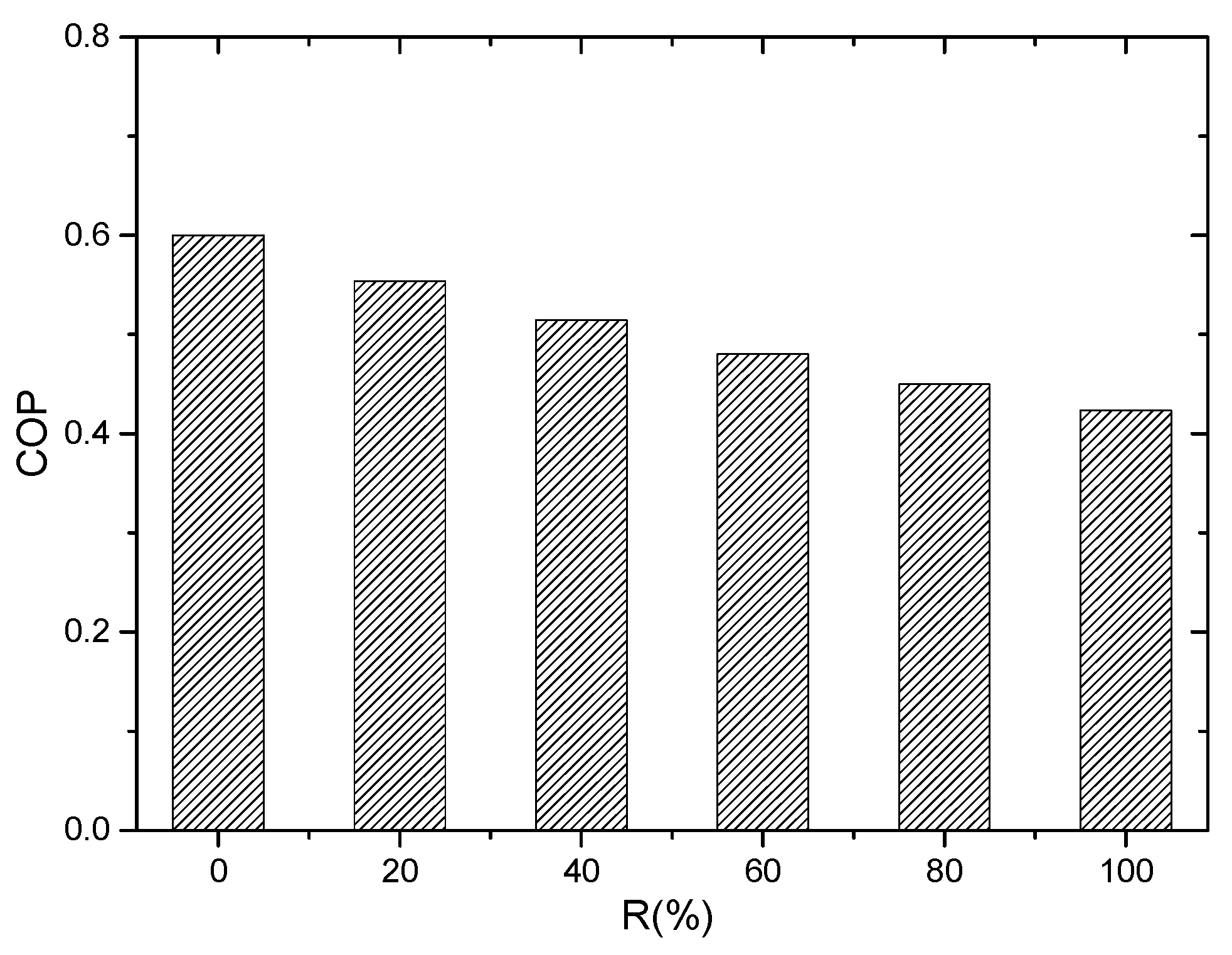
The result of neglecting the energy loss and assuming ζ is 60%, is shown in Figure 14. This shows bigger R or more solute participating in regeneration which leads to the COP drop. When R is 100%, the COP is about 70% of that when R is 0%. Local heating with a smaller liquid body does improve the performance in this way, and it could be better if we take the energy loss into consideration as a smaller body reduces the energy dissipation to the environment.

3.4. COP Evaluation for the System in the Solar Steam Mode

If the system takes the solar steam mode for regeneration, the experimental data can be a basis for performance analysis. The COP can be expressed as:
C O P = Q 0 G = l m e P S .
The cooling load Q0 is the product of l and the evaporation rate me. The evaporation rate can be obtained from the experimental data of mass change in Section 3.1 and Section 3.2. G is the input power and is the product of P, the illumination power of the solar simulator and S, the surface area of the wood material with the solar steam structure. S can be taken as the area of a circle. The values of P and the diameter are given in Section 2.3.
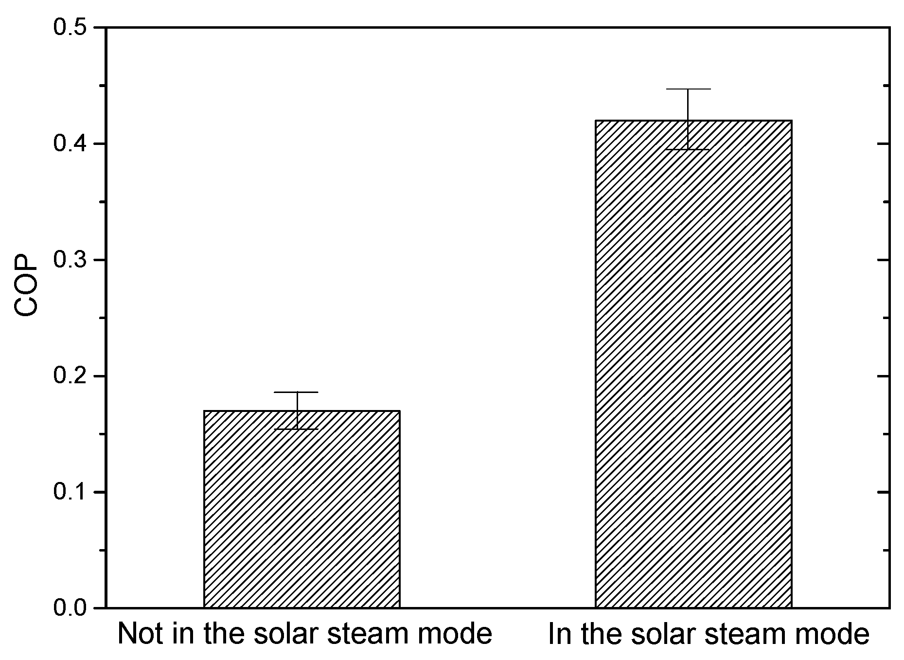
The case of evaporating pure water is investigated first. Based on the experimental data presented in Figure 9, the evaporating performances are calculated with Equation (16) for the pure water of 30 mL in two different modes. Figure 15 presents the results. In the solar steam mode, the COP is more than two times that of the regular evaporation. The situation is the same for regenerating absorbent solution. Based on the experimental data in Figure 6 and Figure 11, the COP is calculated with Equation (16). Figure 16 presents the results. For different concentrations, the COP in the solar steam mode is more than two times and sometimes three times compared to the non-solar steam mode. The COP decreases when the concentration increases. The solar steam mode greatly improves the efficiency of utilizing solar energy. The highest COP exceeds 0.6 when the concentration is 10%. The typical working concentration range of the LiCl solution is about 25–35%. Within this range, the highest COP of the system is about 0.3 in the solar steam mode. It is much lower than that of the vapor compression system. Nevertheless, if the vapor compression system is also driven by solar energy, like the PV power, the COP is about 0.3 with the low conversion efficiency of solar illumination to electric power. With this in mind, the absorption system with the solar steam mode could be a competitive alternative.

4. Conclusions

Local heating regeneration methods are proposed in this paper for the purpose of improving the performance of the absorption system. The idea of the local heating regeneration is to make the heating liquid body as small as possible in order to reduce the energy consumption on liquid temperature rising and energy loss to the environment. Two modes are introduced. One reduces the amount of the liquid sent to regeneration and the other is the solar steam mode, which adopts a material with a specific double layer configuration. Both methods are promising in improving the system efficiency.
With the energy balance equations, analysis has been made on the local heating regeneration idea. The models expose the influence of some parameters, including the concentrations and solution temperature change, which are closely related to the performance of the system adopting this idea. One third of the energy can be saved at most with the minimum volume of the liquid taking part in the regeneration process.
Experiments have been made testing the local heating regeneration idea. For the non-solar steam mode, the size of the liquid body has very little influence on the performance when the surface is directly under the illumination of the solar simulator. The reason for this is because all of these situations can be considered as local heating in the vertical direction. For the solar steam mode, the specific structure of the material brings the local heating effect in both the vertical direction and lateral direction. Therefore, the evaporate rates doubled with pure water as the liquid subject and tripled with LiCl solution as the subject.
The newest research shows the highest efficiency with the solar steam mode can attain 0.8 or more. Xiao et al. studied an efficient solar steam generation of carbon black incorporated hyper-cross-linked polymer composites [32]. Chen et al. studied the highly anisotropic corncob as an efficient solar steam-generation device [33]. Behera et al. proposed an ultra-broadband absorption method for higher efficiency [34]. Yang et al. studied a wood-based solar interface evaporation device for efficient solar steam generation [35]. Zhang et al. proposed an MoS2 nanosheet–carbon foam composite for solar steam generation [36]. However, the highest COP in our experiments reached 0.6 with 10% LiCl solution. The major reason is the difference of the adopted solution subjects. In the newest research, pure water or low concentration NaCl solution is adopted, while LiCl solution with higher concentration was adopted in our experiments. The solution in our experiments had larger capacity of absorbing water vapor, which leads to lower evaporation rate and lower efficiency. The efficiency goes lower with higher concentration.
Though impeded by the solution absorption capability, the local heating regeneration method could improve the COP of the absorption system by 40% in reducing the energy consumption. This COP will be tripled with the solar steam mode. It shows the local heating regeneration methods may have great potential in practical application.
Future work will focus on the optimization of the local heating regeneration mode, like better configuration and better design or more favorable material for the solar steam mode. Theoretical and experimental research is also needed to reveal the mechanism of heat and mass transfer in the local heating regeneration process.

Author Contributions

Conceptualization, X.L; methodology, F.C.; validation, Y.W.; formal analysis, F.C.; investigation, F.C.; resources, X.L.; writing—original draft preparation, F.C.; writing—review and editing, X.L.; supervision, X.L.; project administration, X.L.; funding acquisition, X.L. All authors have read and agreed to the published version of the manuscript.

Funding

This research was funded by the fund of National Natural Science Foundation of China under the contracts No. 51206080 and No. 51676098; the fund of Natural Science Foundation of Jiangsu Province under the contracts No. BK20170095 and No. BK20160822.

Institutional Review Board Statement

The study did not require ethical approval.

Informed Consent Statement

Not applicable.

Data Availability Statement

Data is contained within the article.

Acknowledgments

This research was supported by the grants from the fund of National Natural Science Foundation of China under the contracts No. 51206080 and No. 51676098. It was also supported by the fund of Natural Science Foundation of Jiangsu Province under the contracts No. BK20170095 and No. BK20160822. These supports are gratefully acknowledged.

Conflicts of Interest

The authors declare no conflict of interest.

Nomenclature

Conmass concentration (%)
cpsspecific heat of the solution (kJ kg−1 K−1)
cpwspecific heat of the water vapor (kJ kg−1 K−1)
COPcoefficient of performance (dimensionless)
Genergy input (kJ)
Henthalpy (kJ)
llatent heat of water vaporization (kJ kg−1)
mwamount of evaporated water vapor (kg)
mssolution mass (kg)
Ppower input (kW)
Qiinput energy (kJ)
Qlenergy loss (kJ)
Q0cooling capacity (kJ)
Sarea (m2)
ttemperature (°C)
Greek letters
ζsolar thermal conversion efficiency (%)
Subscripts
1before regeneration
2after regeneration
iin
oout
rregenerator
ssolution
wwater

References

  1. Yang, J.; Mohan Kumar, D.I.; Pyrgou, A.; Chong, A.; Santamouris, M.; Kolokotsa, D.; Lee, S.E. Green and cool roofs’ urban heat island mitigation potential in tropical climate. Sol. Energy 2018, 173, 597–609. [Google Scholar] [CrossRef]
  2. Solangi, Y.A.; Cheng, L.; Shah, S.A.A.; Alsanad, A.; Ahmad, M.; Akbar, M.A.; Gumaei, A.; Ali, S. Analyzing renewable energy sources of a developing country for sustainable development: an integrated fuzzy based-decision methodology. Processes 2020, 8, 825. [Google Scholar] [CrossRef]
  3. Liu, X.; Paritosh, P.; Awalgaonkar, N.M.; Bilionis, I.; Karava, P. Model predictive control under forecast uncertainty for optimal operation of buildings with integrated solar systems. Sol. Energy 2018, 171, 953–970. [Google Scholar] [CrossRef]
  4. Al-Nimr, M.A.; Qananba, K.S. A solar hybrid system for power generation and water distillation. Sol. Energy 2018, 171, 92–105. [Google Scholar] [CrossRef]
  5. Nader, N.; Al-Kouz, W.; Al-Dahidi, S. Assessment of existing photovoltaic system with cooling and cleaning system: Case study at Al-Khobar City. Processes 2020, 8, 9. [Google Scholar] [CrossRef] [Green Version]
  6. Meyers, S.; Schmitt, B.; Vajen, K. The future of low carbon industrial process heat: A comparison between solar thermal and heat pumps. Sol. Energy 2018, 173, 893–904. [Google Scholar] [CrossRef]
  7. Hamrahi, S.E.; Goudarzi, K.; Yaghoubi, M. Experimental study of the performance of a continues solar adsorption chiller using Nano-activated carbon/methanol as working pair. Sol. Energy 2018, 173, 920–927. [Google Scholar] [CrossRef]
  8. Afanasyeva, S.; Bogdanov, D.; Breyer, C. Relevance of PV with single-axis tracking for energy scenarios. Sol. Energy 2018, 173, 173–191. [Google Scholar] [CrossRef]
  9. Awad, H.; Gül, M. Load-match-driven design of solar PV systems at high latitudes in the Northern hemisphere and its impact on the grid. Sol. Energy 2018, 173, 377–397. [Google Scholar] [CrossRef]
  10. Eidan, A.A.; AlSahlani, A.; Ahmed, A.Q.; Al-fahham, M.; Jalil, J.M. Improving the performance of heat pipe-evacuated tube solar collector experimentally by using Al2O3 and CuO/acetone nanofluids. Sol. Energy 2018, 173, 780–788. [Google Scholar] [CrossRef]
  11. Jain, V.; Sachdeva, G.; Kachhwaha, S.S. Comparative performance study and advanced exergy analysis of novel vapor compression-absorption integrated refrigeration system. Energy Convers. Manag. 2018, 172, 81–97. [Google Scholar] [CrossRef]
  12. Shirazi, A.; Taylor, R.A.; Morrison, G.L.; White, S.D. Solar-powered absorption chillers: A comprehensive and critical review. Energy Convers. Manag. 2018, 171, 59–81. [Google Scholar] [CrossRef]
  13. Mahmoudi, S.M.S.; Kordlar, M.A. A new flexible geothermal based cogeneration system producing power and refrigeration. Renew. Energy 2018, 123, 499–512. [Google Scholar] [CrossRef]
  14. Wang, Y.; Li, M.; Du, W.; Yu, Q.; Ji, X.; Ma, X. Performance comparative study of a solar-powered adsorption refrigerator with a CPC collector/adsorbent bed. Energy Convers. Manag. 2018, 173, 499–507. [Google Scholar] [CrossRef]
  15. Wang, Y.; Li, M.; Yu, Q.; Li, G.; Ma, X. Experimental study of the effect of enhanced mass transfer on the performance improvement of a solar-driven adsorption refrigeration system. Appl. Energy 2018, 224, 417–425. [Google Scholar] [CrossRef]
  16. Dai, E.; Lin, M.; Xia, J.; Dai, Y. Experimental investigation on a GAX based absorption heat pump driven by hybrid liquefied petroleum gas and solar energy. Sol. Energy 2018, 169, 167–178. [Google Scholar] [CrossRef]
  17. Patel, B.; Desai, N.B.; Kachhwaha, S.S. Thermo-economic analysis of solar-biomass organic Rankine cycle powered cascaded vapor compression-absorption system. Sol. Energy 2017, 157, 920–933. [Google Scholar] [CrossRef]
  18. Ezzat, M.F.; Dincer, I. Energy and exergy analyses of a new geothermal–solar energy based system. Sol. Energy 2016, 134, 95–106. [Google Scholar] [CrossRef]
  19. Fan, Z.; Ferreira, C.A.I.; Mosaffa, A.H. Numerical modelling of high temperature latent heat thermal storage for solar application combining with double-effect H2O/LiBr absorption refrigeration system. Sol. Energy 2014, 110, 398–409. [Google Scholar] [CrossRef]
  20. El-Shaarawi, M.A.I.; Said, S.A.M.; Siddiqui, F.R. Unsteady thermodynamic analysis for a solar driven dual storage absorption refrigeration cycle in Saudi Arabia. Sol. Energy 2014, 110, 286–302. [Google Scholar] [CrossRef]
  21. Siavashi, M.; Ghasemi, K.; Yousofvand, R.; Derakhshan, S. Computational analysis of SWCNH nanofluid-based direct absorption solar collector with a metal sheet. Sol. Energy 2018, 170, 252–262. [Google Scholar] [CrossRef]
  22. Kumar, R.; Chand, P. Performance prediction of extended surface absorber solar air collector with twisted tape inserts. Sol. Energy 2018, 169, 40–48. [Google Scholar] [CrossRef]
  23. Rodríguez-Sánchez, M.R.; Marugán-Cruz, C.; Acosta-Iborra, A.; Santana, D. Thermo-mechanical modelling of solar central receivers: Effect of incident solar flux resolution. Sol. Energy 2017, 165, 43–54. [Google Scholar] [CrossRef]
  24. Ghasemi, H.; Ni, G.; Marconnet, A.M.; Loomis, J.; Yerci, S.; Miljkovic, N.; Chen, G. Solar steam generation by heat localization. Nat. Commun. 2014, 5449, 1–7. [Google Scholar] [CrossRef] [Green Version]
  25. Kaur, M.; Ishii, S.; Shinde, S.L.; Nagao, T. All-ceramic microfibrous solar steam generator: TiN plasmonic nanoparticle-loaded transparent microfibers. ACS Sustain. Chem. Eng. 2017, 5, 8523–8528. [Google Scholar] [CrossRef]
  26. Yang, J.; Pang, Y.; Huang, W.; Shaw, S.K.; Schiffbauer, J.; Pillers, M.A.; Mu, X.; Luo, S.; Zhang, T.; Huang, Y.; et al. Functionalized graphene enables highly efficient solar thermal steam generation. ACS Nano 2017, 11, 5510–5518. [Google Scholar] [CrossRef] [PubMed]
  27. Yin, Z.; Wang, H.; Jian, M.; Li, Y.; Xia, K.; Zhang, M.; Wang, C.; Wang, Q.; Ma, M.; Zheng, Q.; et al. Extremely black vertically aligned carbon nanotube arrays for solar steam generation. ACS Appl. Mater. Interfaces 2017, 9, 28596–28603. [Google Scholar] [CrossRef]
  28. Jia, C.; Li, Y.; Yang, Z.; Chen, G.; Yao, Y.; Jiang, F.; Kuang, Y.; Pastel, G.; Xie, H.; Yang, B.; et al. Rich mesostructures derived from natural woods for solar steam generation. Joule 2017, 1, 588–599. [Google Scholar] [CrossRef] [Green Version]
  29. Xue, G.; Liu, K.; Chen, Q.; Yang, P.; Li, J.; Ding, T.; Duan, J.; Qi, B.; Zhou, J. Robust and low-cost flame-treated wood for high-performance solar steam generation. ACS Appl. Mater. Interfaces 2017, 9, 15052–15057. [Google Scholar] [CrossRef] [PubMed]
  30. Conde, M.R. Properties of aqueous solutions of lithium and calcium chlorides: Formulations for use in air conditioning equipment design. Int. J. Therm. Sci. 2004, 43, 367–382. [Google Scholar] [CrossRef]
  31. Zeidan, E.B.; Aly, A.A.; Hamed, A.M. Modeling and simulation of solar-powered liquid desiccant regenerator for open absorption cooling cycle. Sol. Energy 2011, 85, 2977–2986. [Google Scholar] [CrossRef]
  32. Xiao, C.H.; Liang, W.D.; Hasi, Q.M.; Wang, F.; Chen, L.; He, J.; Liu, F.; Sun, H.; Zhu, Z.; Li, A. Efficient solar steam generation of carbon black incorporated hyper-cross-linked polymer composites. ACS Appl. Energy Mater. 2020, 3, 11350–11358. [Google Scholar] [CrossRef]
  33. Chen, T.J.; Xie, H.; Qiao, X.; Hao, S.; Wu, Z.; Sun, D.; Lui, Z.; Cao, F.; Wu, B.; Fang, X. Highly anisotropic corncob as an efficient solar steam-generation device with heat localization and rapid water transportation. SACS Appl. Mater. Interfaces 2020, 12, 50397–50405. [Google Scholar] [CrossRef] [PubMed]
  34. Behera, S.; Kim, C.W.; Kim, K.S. Solar steam generation and desalination using ultra-broadband absorption in plasmonic alumina nanowire haze structure–graphene oxide–gold nanoparticle composite. Langmuir 2020, 36, 12494–12503. [Google Scholar] [CrossRef] [PubMed]
  35. Yang, J.; Chen, Y.; Jia, X.H.; Li, Y.; Wang, S.; Song, H. Wood-based solar interface evaporation device with self-desalting and high antibacterial activity for efficient solar steam generation. ACS Appl. Mater. Interfaces 2020, 12, 47029–47037. [Google Scholar] [CrossRef]
  36. Zhang, X.F.; Wu, G.; Yang, X.C. MoS2 Nanosheet–carbon foam composites for solar steam generation. ACS Appl. Nano Mater. 2020, 3, 9706–9714. [Google Scholar] [CrossRef]
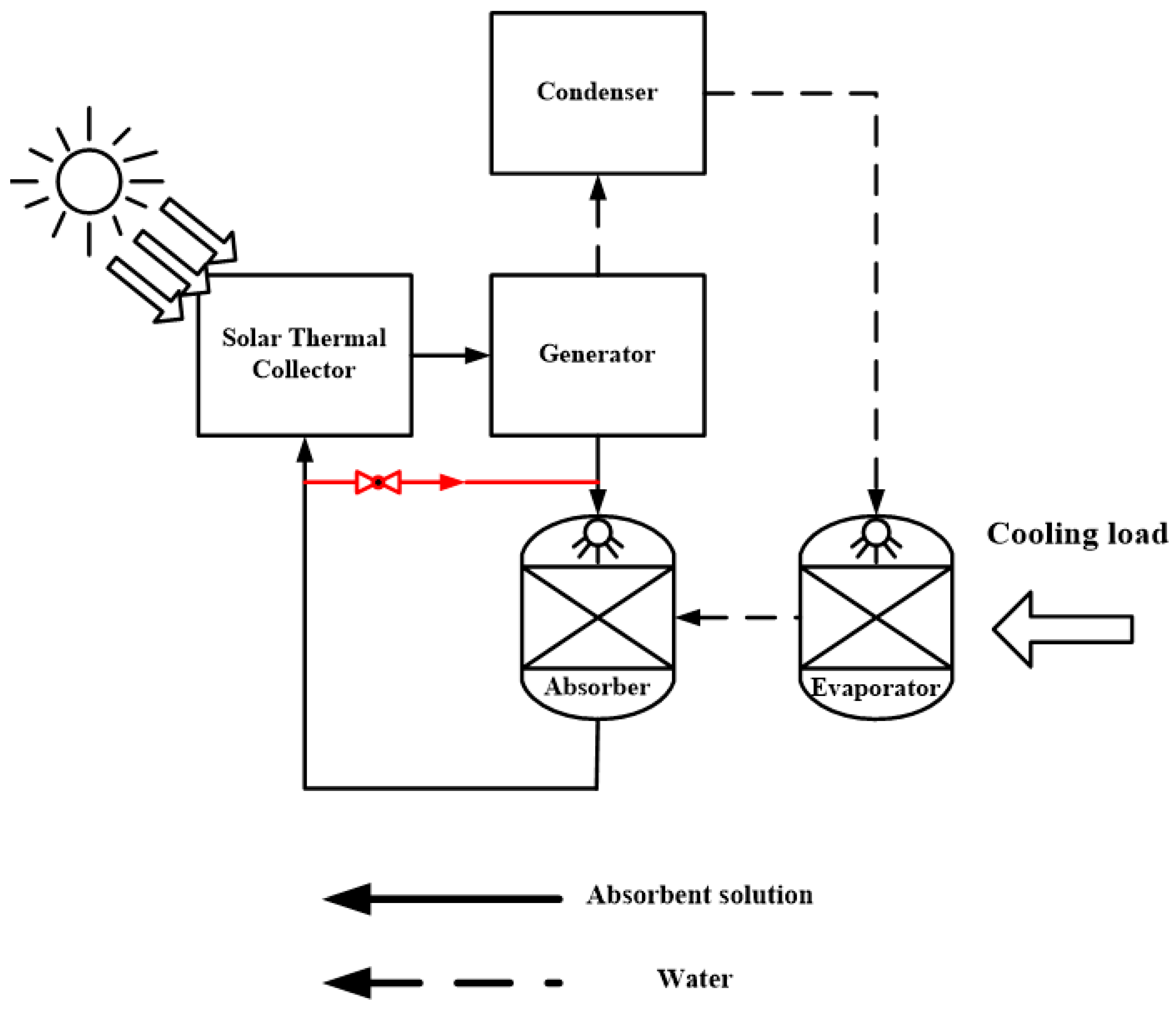
Figure 1. Flow chart of solar energy driven absorption air-conditioning system.
Processes 09 00444 g001
Figure 2. Solar steam mode.
Processes 09 00444 g002
Figure 3. Experimental system.
Processes 09 00444 g003
Figure 4. (a) Wood material before treatment. (b) Wood material after treatment.
Processes 09 00444 g004
Figure 5. Mass change of the water and beaker with different liquid volumes.
Processes 09 00444 g005
Figure 6. Mass change of the beaker and LiCl solution with different concentrations (20 mL).
Processes 09 00444 g006
Figure 7. Mass change of the beaker and LiCl solution with different concentrations (30 mL).
Processes 09 00444 g007
Figure 8. Experiments with the treated wood.
Processes 09 00444 g008
Figure 9. Evaporation rates of water with and without the solar steam structure material.
Processes 09 00444 g009
Figure 10. “Steam” phenomenon.
Processes 09 00444 g010
Figure 11. Evaporation rates of LiCl solution with the solar steam structure material (20 mL).
Processes 09 00444 g011
Figure 12. Evaporation rates of LiCl solution with solar steam structure material (30 mL).
Processes 09 00444 g012
Figure 13. Wood after experiments.
Processes 09 00444 g013
Figure 14. COP with different mass ratio.
Processes 09 00444 g014
Figure 15. COP of evaporating pure water in different modes.
Processes 09 00444 g015
Figure 16. COP of the absorption system with LiCl solution as the absorbent in different modes.
Processes 09 00444 g016
Publisher’s Note: MDPI stays neutral with regard to jurisdictional claims in published maps and institutional affiliations.