Abstract
This paper investigated the mechanical response (including breakage and release of the internal liquid) of single core–shell capsules under compression by means of discrete multi-physics. The model combined Smoothed Particle Hydrodynamics for modelling the fluid and the Lattice Spring Model for the elastic membrane. Thanks to the meshless nature of discrete multi-physics, the model can easily account for the fracture of the capsule’s shell and the interactions between the internal liquid and the solid shell. The simulations replicated a parallel plate compression test of a single core–shell capsule. The inputs of the model were the size of the capsule, the thickness of the shell, the geometry of the internal structure, the Young’s modulus of the shell material, and the fluid’s density and viscosity. The outputs of the model were the fracture type, the maximum force needed for the fracture, and the force–displacement curve. The data were validated by reproducing equivalent experimental tests in the laboratory. The simulations accurately reproduced the breakage of capsules with different mechanical properties. The proposed model can be used as a tool for designing capsules that, under stress, break and release their internal liquid at a specific time.
1. Introduction
A capsule is a solid material enclosing an active substance, often in liquid form. The internal structure of the capsules can vary significantly depending on the encapsulation method and the materials used [1,2,3]. It can have a simple single-core shell [4], a multicore shell, or a porous structure where the liquid is trapped [5]. Often, the purpose of the capsule is to ensure a controlled release of the liquid inside. With this aim, they are widely used in a variety of fields [6], including cosmetics [7], food [8], textiles [9], pharmacy [10], agriculture [11], and, more recently, for self-healing materials such as self-repairing concrete [12] or asphalt [13,14].
Mechanical characterisation is essential to the design of capsules for a timely release of an active substance [15]. It provides information about material parameters such as the Young’s modulus and the stress-strain relationship that are key factors in designing capsules fit for their intended application. Currently, capsules are designed for end-use applications by trial and error. Computer simulations have the potential to significantly accelerate their design by providing a method for predicting the behaviour of the capsule in advance.
Conventional modelling techniques like the Finite Element Method (FEM) can be used to calculate stress in shells [16], but they are less effective when the simulation includes the fracture of the shell. Modelling fluid–solid interactions, occurring after the fracture of the shell and the consequent release of the fluid, is another main challenge. This issue could be solved by coupling FEM with Smoothed Particle Hydrodynamics (SPH) [17], but this method cannot accurately reproduce the fracture of the shell. Other computational techniques, such as Computational Fluid Dynamics (CFD), Lattice–Boltzmann (LB), and Boundary Integral Methods (BIMs), have been used for simulating solid–fluid flows. However, none of them can simulate breakable solids accurately. Recently, a mesh-free Discrete Multi-Physics (DMP) approach has been implemented to simulate the interactions between fluid and solid particles [18,19]. DMP is based on a particle framework that couples different particle models: SPH to simulate the hydrodynamics of liquid, and the Lattice Spring Model (LSM) to simulate a solid (including high deformations and fracture). These methods share a common particle-based paradigm and, therefore, are easy to couple together. This approach has been validated for a variety of fluid–solid problems. Some examples are the hydrodynamics in the colon [20], motile cilia in the lungs [21], emboli in flexible venous valves [22], phase-change in circular pipes [23], and the deformation and rupture of nucleated cells under shear flows [24].
In this paper, DMP was used to simulate a 3D elastic core–shell capsule breaking under compression and releasing its internal liquid into the environment. To the best of our knowledge, this is the first model capable of simulating this phenomenon. The proposed model is an extension of [24], but, in this case, rupture occurs by direct compression of the capsule rather than as a result of shear flow. The computational results were validated by comparing the type of fracture of the capsule and the force/displacement relationship with experimental data for elastic core–shell capsules available in the literature [25]. DMP can effectively reproduce the deformation and the fracture of the capsule. The model was used to study the influence of the shell’s Young’s modulus and thickness on the force/displacement relationship and on the type of fracture to show how the proposed model could have a significant impact on the design of capsules [26].
2. Methodology
2.1. Modelling Approach
The version of DMP used in this paper (Figure 1) couples SPH and the LSM. SPH was used to model the fluid, and LSM was used for the solid. Details on these models and how they were coupled together are given in this section.
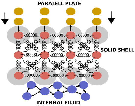
Figure 1.
Particle representation and interactions among the computational particles.
2.1.1. Smoothed Particle Hydrodynamics (SPH)
Here, only a very general introduction to SPH is given; for additional details, see [27]. The general idea of SPH is to approximate a partial differential equation over a group of movable computational particles that are not collocated over a grid or a mesh [28]. Each particle has an associated mass, momentum, and energy and the motion of the particle is calculated by integrating Newton’s second law. Particle properties such as density, velocity, energy per unit of mass, pressure, or heat flux are obtained by interpolating neighbouring particles by means of:
where f(r) is a generic property defined over the volume, r is the position vector where the property is measured, W is the so-called Kernel function, and h is a smoothing length [27]. We used the Lucy kernel [29]. The Navier–Stokes equation, for instance, can be discretised over a series of computational particles, obtaining:
where P is the pressure, t represents time, v is the velocity, m is the mass, ρ is the density associated with particles i and j, and FE refers to the external forces acting on the fluid (e.g., gravity). The viscosity term ( used in this study is defined in [30]. Equation (2) requires an equation of state that relates density and pressure. In this work, we used Tait’s equation [31]:
where c0 is a reference speed of sound and ρ0 is a reference density. To ensure weak compressibility, c0 was chosen to be at least 10 times larger than the highest fluid velocity.
Πij in Equation (2) introduces the viscosity tensor; here, we used the so-called artificial viscosity [30], defined as:
where vij = vj − vi and ρij = ρj + ρi. The dimensionless parameters α and b ensure the stability of the simulation. In our case, b = 0.01, while:
where ν is the kinematic viscosity. At each time step, the local density is updated according to the partition of unity equation [30]:
2.1.2. Lattice Spring Model (LSM)
The LSM was used to model the shell of the capsule. Here, only a very general introduction to LSM is given; for additional details see [32]. The computational particles that constitute the solid shell are linked together by spring-like bonds and their trajectories calculated with the Newtonian equations of motion:
where Utot is the potential used to model the bonds between interconnected particles. In this study, linear spring was used, which corresponds to the harmonic potential:
where is the equilibrium distance and kb is the Hookean constant. The Young’s modulus of the materials relates to kb, as explained in Section 2.3.
Equation (8) represents the forces that maintain two particles at a specific distance (r0). The distribution of the shell’s computational particles is determined by defining a quadratic mesh (see Figure 1) over an empty sphere with external diameter 3.1 × 10⁻⁵ m and an internal diameter of 2.6 × 10⁻⁵ m. Nearest neighbour particles and next-nearest neighbour particles are linked with computational springs. Breakage is simulated assuming that, if the distance between two particles exceeds a maximal value (rmax), the bond is broken and the two particles separated (Figure 2).
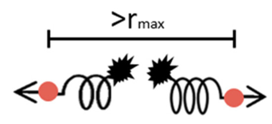
Figure 2.
Representation of two computed particle bonds breaking.
How kb and rmax are calibrated to reproduce the capsule mechanical properties is discussed later on.
2.1.3. Coupling the Two Models
Besides the interaction between two liquid particles (model with SPH) and two solid particles (model with LSM), the model also requires specifying the interaction between liquid and solid particles that occurs at the solid–liquid interface. Here, only a general introduction to coupling SPH and LSM is given; for more details, see [33]. In continuum mechanics, three conditions must be satisfied:
where n is the vector normal to the boundary, u is the displacement of the solid, v is the velocity of the liquid, and σs is the stress tensor in the solid and σf in the fluid.
σs∙n = σf∙(−n) (continuity of stresses condition)
The advantage of using a particle method is that we only solve the Newton equation of motion for every particle. The only difference is in the force acting on the particle. Equations (9)–(11) are no exceptions. They do not need a special treatment, but only forces that replicate the effect of the boundary conditions. For Equation (9), this is achieved by using the repulsive potential of the type:
where the constants , σ, a, and b are given in Table 1. This repulsion force does not influence the simulation itself. It is only used to avoid particle compenetrating and its parameters are determined to achieve this goal without requiring a smaller time step. The cut-off r < σ in Equation (12) ensures that, when the particles are not in contact, the force is zero. The parameters in Equation (9) were chosen by trial and error to guarantee no penetration without decreasing the timestep. If the repulsion potential is too weak, fluid will penetrate inside the solid; if it is too strong, the simulation will require small timesteps to remain stable.

Table 1.
Parameters needed for Discrete Multi-Physics simulation.
No-slip conditions are modelled by superimposing virtual fluid particles above the solid particles at the interface, providing zero relative velocity at the solid–liquid boundary for the liquid particles that interact with the interface. Finally, in particle methods, the continuity-of-stress is automatically satisfied (it is a consequence of the law of action–reaction) and does not require to be specificity implemented.
The calculations were carried out with LAMMPS, a molecular dynamics software package that also accounts for other particle methods, such as SPH. The reader is referred to [34,35] for additional details on the numerical formulations and schemes used in the simulation of, respectively, the structure and the fluid.
The model does not account for temperature changes. However, this can be easily implemented in DMP [18].
2.2. Geometry
The starting geometry in the simulations was a three-dimensional single liquid core capsule with a diameter of 0.031 mm. As the purpose of this simulation was to simulate compression of single particles between two parallel plates, the drivers were defined as rectangular geometries that apply force to the capsule. The parallel plates were modelled with solid particles (Figure 3). The lower plate was stationary, while the upper plate moved as a rigid body under the effect of an applied force that compressed the capsules during the compression test.

Figure 3.
Initial simulation geometry.
Figure 3 shows the geometry of the shell and the parallel plates at the beginning of the simulation. A transversal cut of the capsule shows the fluid particles inside the capsule. In order to prevent penetration, repulsive forces were used between the fluid and the shell, the fluid and the plates, and the shell and the plates by applying no-penetration and no-slip boundary conditions, as explained in the previous section. The shell was built with three particle layers. Simulations with additional layers (i.e., more particles) were carried out and show similar results. In this study, we only considered elastic capsules. Viscoelastic can be modelled by implementing the method proposed in [36]. From Figure 3, it can be appreciated that the shell was not completely filled with fluid. The empty space was created by the small deformation of the capsule due to gravity and the resulting settling of the fluid particles. In theory, it is possible to add more particles to replenish the capsule. However, we decided not to do this, since the same phenomenon can also occur in real particles. This space is normally within 1%–2% of the total volume. We verified that within this range, and the results were not affected.
2.3. Main Simulation Parameters
The parameters used in the simulations can be divided into three groups (i.e., SPH, MSM, and boundaries) and are shown in Table 1.
The parameter that determines the elastic behaviour of the model is kb, the Hookean coefficient of the computational springs. The actual Young’s modulus of the capsules can be calculated from compression experiments with the technique proposed by Yap et al. [37]. In our case, it corresponds to E = 4.85 MPa. Once the Young’s modulus is known, the value of kb can be calculated with the following equation [38]:
where E is the Young’s modulus, t0 is the thickness of the shell of the capsule, and n is the number of layers of the shell. The timestep used in the simulation was Δt = 1 × 10⁻¹⁰ s. We carried out a sensitivity analysis of the results with the timestep to make sure the results were independent of the timestep adopted.
The parallel plates applied a progressive pressure to the capsule until the capsule broke, replicating the experimental conditions. From the simulations, therefore, we can plot the force–displacement data and, for validation purposes, compare the plot with that obtained from the experiments.
2.4. Parametric Study and Influence of kb and rmax
The capsule’s deformability and strength are governed by two parameters: the Hookean coefficient of the computational springs (kb) and the maximum distance between solid particles after which the computational spring breaks (rmax). In order to analyse the influence of these parameters on the deformability, strength, and type of fracture of the capsule, the main simulation, fitted to the experimental force–displacement curve, was assessed in 9 different simulations modifying kb (1.56, 4.67, and 14 N m−1) and rmax (1.03∙r0, 1.2∙r0, and 1.27∙r0) values. Many other authors have applied similar methodologies in order to perform sensitivity analysis in different fields [39,40,41,42].
3. Results and Discussion
3.1. Validation of the Simulation of Capsule Compression between Two Parallel Plates
A parallel compression test of a single core–shell capsule under compressive load was reproduced in the simulations. The force–displacement curve obtained from these simulations was compared to the corresponding data obtained experimentally [25] for a core–shell with the same size and internal structure. For validation purposes, we compared the results with only one type of capsule available in the literature [25]. However, it must be noted that the parameters kb describing the mechanical properties of the capsule are calculated by first-principles Equation (13), and are is not the result of fitting a free parameter to the experimental data.
In order to determine the optimal resolution of the core–shell model, various simulations with an increasing number of computational particles were compared. Each simulation had a different layer used to model the shell. The best compromise between accuracy and computational times was found with three layers. Figure 4 compares the force–displacement curve obtained with the model and with the experiments. Furthermore, an additional simulation with the capsule without fluid inside was carried out in order to understand the influence of the fluid on the capsule´s strength.
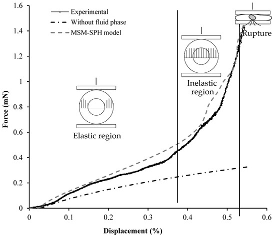
Figure 4.
Force–displacement curve obtained from a laboratory parallel plate compression test for a single core–shell capsule, from a simulated single core–shell capsule without fluid inside and from a simulated single core–shell capsule. The upper plate displacement was expressed in %, taking into consideration the initial y-axis dimension of the capsule.
The results show that the compression can be divided into three regions: (i) an elastic region where the force is proportional to δ3/2 (where δ is the displacement), as predicted by Hertzian theory, and all of the load is supported by the external shell; (ii) an inelastic region where the stress reaches the fluid that adds additional resistance to the compression; (iii) a final region where the capsule breaks and collapses.
These three different stages were observed in both the experimental and the DMP force–displacement curves. The DMP results are very similar to the experimental results and reached the same maximal force required to break the capsule. The force–displacement curve from the simulation of the shell without fluid shows a completely different shape, which indicates that the internal fluid affects significantly the deformation of the capsule, especially at high deformations. It is important to highlight that the model does not account for plastic deformation. Locally, the rupture of every single bond was “fragile.” However, this still produced a gradual rupture at the global level. In Figure 4, for instance, we defined the region before the rupture as “inelastic” because we did not observe capsule break-up. However, some of the bonds in the solid structure began to rupture, weakening the structure and producing the observed inelastic behaviour.
Figure 5 shows that the DMP model is consistent with the fracture and the capsule deformation for different coaxial load values applied during the compression test of the real capsule tested in the laboratory [25]. In order to save computational time, the resulting speed of the driver was higher in the simulations shown in Figure 5. However, quasi-static conditions were verified by carrying out simulations at different driver speeds, enabling a comparison between the force–displacement curves.
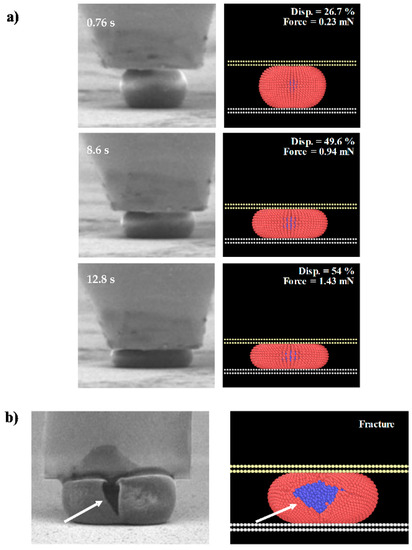
Figure 5.
(a) Comparison between the deformation under coaxial load and (b) the fracture of a simulated elastic single liquid core–shell capsule by the Discrete Multi-Physics (DMP) approach and an elastic capsule of 16–50 µm being ruptured (from [43]).
3.2. Influence of the Fluid on the Capsule’s Strength
Taking into consideration the previous results, it can be said that the internal liquid has an important effect on the force–displacement relationship.
Figure 6 shows an image sequence of the simulation of the parallel compression test of a single liquid core–shell capsule. Figure 6a shows the pressure of the internal fluid at the beginning of the test. As the capsule was compressed by the upper plate load and deformed, the pressure increased due to the load applied by the upper plate (Figure 6b,c). Finally, when the capsule started to break, the pressure of the fluid inside the capsule reduced because of the fluid released through the broken shell (Figure 6d).
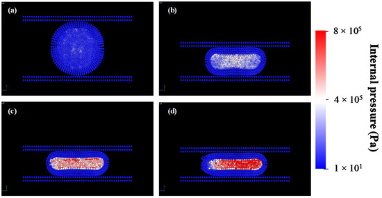
Figure 6.
Simulation sequence of the parallel compression test of a single liquid core–shell capsule at different stages: (a) beginning of the simulation, (b) high deformation and slight increment of internal pressure, (c) slight deformation and significant increment of internal pressure and (d) fracture of the capsule.
3.3. Deformability and Strength of the Capsule (a Parametric Study)
In this section, a parametric study was carried out to understand how the behaviour of the capsule is affected by its mechanical properties: in particular, by kb (which is related to the Young’s modulus by Equation (13) and rmax (which provides the maximal local displacement before rupture). We studied three values of kb (i.e., 14, 4.7, and 1.6 N m−1) and rmax (i.e., 1.03∙r0, 1.2∙r0, and 1.27∙r0), and all nine possible pairings of these parameters.
Lower rmax values imply that the distances required to break the computational springs are shorter. This can be seen, for instance, in Figure 7b. Given the same kb, the capsule broke when the displacement reached 45% for rmax = 1.03∙r0 and 54% for rmax = 1.2∙r0. The load that initiated the breakage of the capsule was also lower (0.54 versus 1.46 mN). This effect was observed for all three values of kb, but it was more evident at high values of kb.
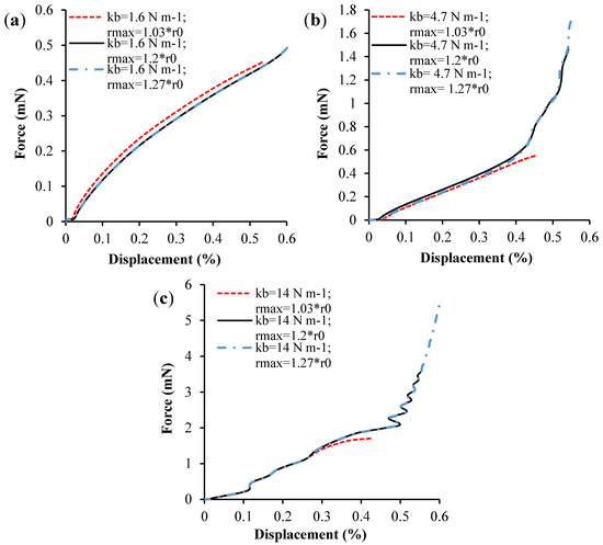
Figure 7.
Simulated force–displacement curves for (a) kb = 1.6 N−1 m and a range of rmax values, (b) kb = 4.7 N−1 m and different values of rmax and (c) kb = 1.6 N−1 m and different values of rmax.
As Figure 7 and Figure 8 show, lower values of rmax mean that the local deformations required to break a computational bond are lower. As a result of this, breakage occurred at lower displacements in the simulations where rmax was lower. High values of kb mean high Young’s moduli (see Equation (13)). The shell was more rigid and, when it broke, the fracture started at a single location and propagated from there, forming a single wedge-shaped gash. When kb was low, the capsule was flexible and showed little resistance to compression. In this case, the capsule tended to break at various locations at the same time during compression.
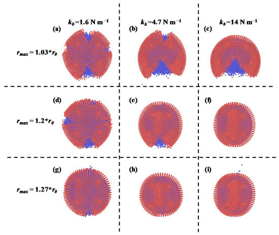
Figure 8.
Capsule fractures (view from the top) at the end of each simulation for (a) kb =1.6 N m−1 and rmax = 1.03 * r0; (b) kb =4.7 N m−1 and rmax = 1.03 * r0; (c) kb = 14 N m−1 and rmax = 1.03 * r0; (d) kb = 1.6 N m−1 and rmax = 1.2 * r0; (e) kb =4.7 N m−1 and rmax = 1.2 * r0; (f) kb = 14 N m−1 and rmax = 1.2 * r0; (g) kb = 1.6 N m−1 and rmax = 1.27 * r0; (h) kb = 4.7 N m−1 and rmax = 1.27 * r0; (i) kb = 14 N m−1 and rmax = 1.27 * r0;
4. Conclusions
This study proposed a Discrete Multi-Physics model to simulate capsules formed by a shell containing a fluid. The liquid core was implemented with Smoothed Particle Hydrodynamics and the solid shell with the Lattice Spring Model.
The model was validated against experimental compression of a single core–shell capsule between two parallel plates. The results showed that the model replicates with good accuracy the behaviour of the real capsule. Three different stages were highlighted in the force–displacement curve occurring during the compression. In the first stage, the load was supported by the external shell and the behaviour was Hertzian (i.e., the force was proportional to δ3/2). During the second stage, the stress reached the fluid, which added additional resistance to the compression. Finally, in the third stage, the capsule broke and collapsed.
After the model had been validated, we carried out a parametric study that showed how the breakage of the capsule depended on its material properties. By changing the material properties, we varied (i) the maximal stress the capsule can resist before breaking, and (ii) the mode of breakage. In some cases, the shell cracked at one point that opened a wide gash in the capsule. In other cases, the shell fractured at multiple locations. This affected the way the liquid was released from the capsule. In the first scenario, the release was not uniform and was concentrated at one side of the capsule. In the second, the liquid was released from multiple points distributed around the capsule.
The proposed model can help the design of capsules with specific features. For instance, we can adjust the mechanical properties of the capsule to make sure that it breaks only when a precise stress level is reached. The model also simulates the liquid release occurring after breakage. In this way, we can design the capsule to make sure that the liquid is released effectively. In fact, the capsule breaks in different ways according to its mechanical properties, and only specific combinations of these properties allow for a uniform release of the liquid after breakage.
Author Contributions
Conceptualization, I.N.R.-R., A.A., Z.Z. and A.G.H.; Methodology, I.N.R.-R. and A.A.; Software, I.N.R.-R. and A.A.; Validation, I.N.R.-R., A.A. and Z.Z.; Formal analysis, I.N.R.-R. and A.A.; Investigation, I.N.R.-R. and A.A.; Data curation, I.N.R.-R.; Writing—original draft preparation, I.N.R.-R.; Writing—review and editing, I.N.R.-R., A.A., Z.Z. and A.G.H.; Project administration, I.N.R.-R. and A.G.H.; Supervision, A.G.H. and A.A.; Project administration, I.N.R.-R. and A.G.H.; Funding acquisition, A.G.H. All authors have read and agreed to the published version of the manuscript.
Funding
This research received funding from the European Union’s H2020 Programme for research, technological development, and demonstration under grant agreement number 721493.
Institutional Review Board Statement
Not applicable.
Informed Consent Statement
Not applicable.
Data Availability Statement
The data presented in this study are available on request from the corresponding author.
Acknowledgments
The research presented in this paper was carried out as part of the H2020-MSCA-ETN-2016.
Conflicts of Interest
The authors declare no conflict of interest.
References
- Trojanowska, A.; Nogalska, A.; Garcia, R.; Giamberini, M.; Tylkowski, B. Technological Solutions for Encapsulation. J. Magn. Magn. Mater. 2017, 2, 1–20. [Google Scholar]
- Martins, E.; Poncelet, D.; Rodrigues, R.C.; Renard, D. Oil Encapsulation Techniques Using Alginate as Encapsulating Agent: Applications and Drawbacks. J. Microencapsul. 2017, 34, 754–771. [Google Scholar] [CrossRef]
- Thuong, N.P.; Thanh, V.T.; Cang, M.H.; Lam, T.D.; Huong, N.C.; Hong Nhan, L.T.; Truc, T.T.; Tran, Q.T.; Bach, L.G. Microencapsulation of Lemongrass (Cymbopogon Citratus) Essential Oil via Spray Drying: Effects of Feed Emulsion Parameters. Processes 2020, 8, 40. [Google Scholar] [CrossRef]
- O’Sullivan, M.; Zhang, Z.; Vincent, B. Silica-Shell/Oil-Core Microcapsules with Controlled Shell Thickness and Their Breakage Stress. Langmuir 2009, 25, 7962–7966. [Google Scholar] [CrossRef]
- Norambuena-contreras, J.; Yalcin, E.; Garcia, A.; Al-mansoori, T.; Yilmaz, M.; Hudson-griffiths, R. Effect of Mixing and Ageing on the Mechanical and Self-Healing Properties of Asphalt Mixtures Containing Polymeric Capsules. Constr. Build. Mater. 2018, 175, 254–266. [Google Scholar] [CrossRef]
- Zhu, D.Y.; Rong, M.Z.; Zhang, M.Q. Self-Healing Polymeric Materials Based on Microencapsulated Healing Agents: From Design to Preparation. Prog. Polym. Sci. 2015, 49–50, 175–220. [Google Scholar] [CrossRef]
- Casanova, F.; Santos, L. Encapsulation of Cosmetic Active Ingredients for Topical Application-a Review. J. Microencapsul. 2016, 33, 1–17. [Google Scholar] [CrossRef]
- Tsai, F.H.; Chiang, P.Y.; Kitamura, Y.; Kokawa, M.; Islam, M.Z. Producing Liquid-Core Hydrogel Beads by Reverse Spherification: Effect of Secondary Gelation on Physical Properties and Release Characteristics. Food Hydrocoll. 2017, 62, 140–148. [Google Scholar] [CrossRef]
- Stan, M.S.; Chirila, L.; Popescu, A.; Radulescu, D.M.; Radulescu, D.E.; Dinischiotu, A. Essential Oil Microcapsules Immobilized on Textiles and Certain Induced Effects. Materials 2019, 12, 2029. [Google Scholar] [CrossRef]
- Rodríguez-Dorado, R.; Landín, M.; Altai, A.; Russo, P.; Aquino, R.P.; Del Gaudio, P. A Novel Method for the Production of Core-Shell Microparticles by Inverse Gelation Optimized with Artificial Intelligent Tools. Int. J. Pharm. 2018, 538, 97–104. [Google Scholar] [CrossRef]
- Sheng, W.; Li, W.; Li, B.; Li, C.; Xu, Y.; Guo, X.; Zhou, F.; Jia, X. Mussel-Inspired Photografting on Colloidal Spheres: A Generalized Self-Template Route to Stimuli-Responsive Hollow Spheres for Controlled Pesticide Release. Macromol. Rapid Commun. 2015, 36, 1640–1645. [Google Scholar] [CrossRef]
- Huang, H.; Ye, G.; Qian, C.; Schlangen, E. Self-Healing in Cementitious Materials: Materials, Methods and Service Conditions. Mater. Des. 2016, 92, 499–511. [Google Scholar] [CrossRef]
- García, Á.; Schlangen, E.; Van De Ven, M. Properties of Capsules Containing Rejuvenators for Their Use in Asphalt Concrete. Fuel 2011, 90, 583–591. [Google Scholar] [CrossRef]
- Al-Mansoori, T.; Norambuena-Contreras, J.; Micaelo, R.; Garcia, A. Self-Healing of Asphalt Mastic by the Action of Polymeric Capsules Containing Rejuvenators. Constr. Build. Mater. 2018, 161, 330–339. [Google Scholar] [CrossRef]
- Mercadé-Prieto, R.; Zhang, Z. Mechanical Characterization of Microspheres Capsules, Cells and Beads: A Review. J. Microencapsul. 2012, 29, 277–285. [Google Scholar] [CrossRef] [PubMed]
- Walter, J.; Salsac, A.V.; Barthes-Biesel, D.; Le Tallec, P. Coupling of Finite Element and Boundary Integral Methods for a Capsule in a Stokes Flow. Int. J. Numer. Methods Eng. 2010, 83, 829–850. [Google Scholar] [CrossRef]
- Müller, M.; Schirm, S.; Teschner, M.; Heidelberger, B.; Gross, M. Interaction of Fluids with Deformable Solids. Comput. Animat. Virtual Worlds 2004, 15, 159–171. [Google Scholar] [CrossRef]
- Alexiadis, A. The Discrete Multi-Hybrid System for the Simulation of Solid-Liquid Flows. PLoS ONE 2015, 10, e0124678. [Google Scholar] [CrossRef]
- Ariane, M.; Wen, W.; Vigolo, D.; Brill, A.; Nash, F.G.B.; Barigou, M.; Alexiadis, A. Modelling and Simulation of Flow and Agglomeration in Deep Veins Valves Using Discrete Multi Physics. Comput. Biol. Med. 2017, 89, 96–103. [Google Scholar] [CrossRef]
- Alexiadis, A.; Stamatopoulos, K.; Wen, W.; Batchelor, H.K.; Bakalis, S.; Barigou, M.; Simmons, M.J.H. Using Discrete Multi-Physics for Detailed Exploration of Hydrodynamics in an in Vitro Colon System. Comput. Biol. Med. 2017, 81, 188–198. [Google Scholar] [CrossRef]
- Ariane, M.; Kassinos, S.; Velaga, S.; Alexiadis, A. Discrete Multi-Physics Simulations of Diffusive and Convective Mass Transfer in Boundary Layers Containing Motile Cilia in Lungs. Comput. Biol. Med. 2018, 95, 34–42. [Google Scholar] [CrossRef]
- Ariane, M.; Vigolo, D.; Brill, A.; Nash, F.G.B.; Barigou, M.; Alexiadis, A. Using Discrete Multi-Physics for Studying the Dynamics of Emboli in Flexible Venous Valves. Comput. Fluids 2018, 166, 57–63. [Google Scholar] [CrossRef]
- Alexiadis, A.; Ghraybeh, S.; Qiao, G. Natural Convection and Solidification of Phase-Change Materials in Circular Pipes: A SPH Approach. Comput. Mater. Sci. 2018, 150, 475–483. [Google Scholar] [CrossRef]
- Rahmat, A.; Barigou, M.; Alexiadis, A. Deformation and Rupture of Compound Cells under Shear: A Discrete Multiphysics Study. Phys. Fluids 2019, 31. [Google Scholar] [CrossRef]
- Mercadé-Prieto, R.; Nguyen, B.; Allen, R.; York, D.; Preece, J.A.; Goodwin, T.E.; Zhang, Z. Determination of the Elastic Properties of Single Microcapsules Using Micromanipulation and Finite Element Modeling. Chem. Eng. Sci. 2011, 66, 2042–2049. [Google Scholar] [CrossRef]
- Gray, A.; Egan, S.; Bakalis, S.; Zhang, Z. Determination of Microcapsule Physicochemical, Structural, and Mechanical Properties. Particuology 2016, 24, 32–43. [Google Scholar] [CrossRef]
- Monaghan, J.J. Smoothed Particle Hydrodynamics. Rep. Prog. Phys. 2005, 68, 1703–1759. [Google Scholar] [CrossRef]
- Huang, Y.J.; Nydal, O.J. Coupling of Discrete-Element Method and Smoothed Particle Hydrodynamics for Liquid-Solid Flows. Theor. Appl. Mech. Lett. 2012, 2, 012002. [Google Scholar] [CrossRef][Green Version]
- Lucy, L.B. A Numerical Approach to the Testing of the Fission Hypothesis. Astron. J. 1977, 82, 1013–1024. [Google Scholar] [CrossRef]
- Morris, J.P.; Fox, P.J.; Zhu, Y. Modeling Low Reynolds Number Incompressible Flows Using SPH. Int. J. Numer. Methods Fluids 1997, 136, 214–226. [Google Scholar] [CrossRef]
- Cole, R.H. Underwater Explosions; Pinceton University Press: Pinceton, NJ, USA, 1948. [Google Scholar]
- Kot, M.; Nagahashi, H.; Szymczak, P. Elastic Moduli of Simple Mass Spring Models. Vis. Comput. 2015, 31, 1339–1350. [Google Scholar] [CrossRef]
- Alexiadis, A. A New Framework for Modelling the Dynamics and the Breakage of Capsules, Vesicles and Cells in Fluid Flow. Procedia IUTAM 2015, 16, 80–88. [Google Scholar] [CrossRef]
- Plimpton, S. Fast Parallel Algorithms for Short-Range Molecular Dynamics. J. Comput. Phys. 1995, 117, 1–19. [Google Scholar] [CrossRef]
- Ganzenm, G.C.; Steinhauser, M.O.; Van Liedekerke, P. The Implementation of Smooth Particle Hydrodynamics in LAMMPS. 2011; pp. 1–23. Available online: https://lammps.sandia.gov/doc/PDF/SPH_LAMMPS_userguide.pdf (accessed on 10 December 2018).
- Sahputra, I.H.; Alexiadis, A.; Adams, M.J. A Coarse Grained Model for Viscoelastic Solids in Discrete Multiphysics Simulations. ChemEngineering 2020, 4, 30. [Google Scholar] [CrossRef]
- Yap, S.F.; Adams, M.J.; Seville, J.P.K.; Zhang, Z. Single and Bulk Compression of Pharmaceutical Excipients: Evaluation of Mechanical Properties. Powder Technol. 2008, 185, 1–10. [Google Scholar] [CrossRef]
- Van Liedekerke, P.; Tijskens, E.; Ramon, H.; Ghysels, P.; Samaey, G.; Roose, D. Particle-Based Model to Simulate the Micromechanics of Biological Cells. Phys. Rev. E Stat. Nonlinear Soft Matter Phys. 2010, 81, 1–15. [Google Scholar] [CrossRef]
- Ghasemi, H.; Darjani, S.; Mazloomi, H.; Mozaffari, S. Preparation of Stable Multiple Emulsions Using Food-Grade Emulsifiers: Evaluating the Effects of Emulsifier Concentration, W/O Phase Ratio, and Emulsification Process. SN Appl. Sci. 2020, 2. [Google Scholar] [CrossRef]
- Ghasemi, H.; Aghabarari, B.; Alizadeh, M.; Khanlarkhani, A.; Abu-Zahra, N. High Efficiency Decolorization of Wastewater by Fenton Catalyst: Magnetic Iron-Copper Hybrid Oxides. J. Water Process Eng. 2020, 37, 101540. [Google Scholar] [CrossRef]
- Sokolov, A.; Mozaffari, A.; Zhang, R.; De Pablo, J.J.; Snezhko, A. Emergence of Radial Tree of Bend Stripes in Active Nematics. Phys. Rev. X 2019, 9, 31014. [Google Scholar] [CrossRef]
- Li, J.; Dong, S.; Hua, W.; Li, X.; Pan, X. Numerical Investigation of Hydraulic Fracture Propagation Based on Cohesive Zone Model in Naturally Fractured Formations. Processes 2019, 7, 28. [Google Scholar] [CrossRef]
- Ren, Y.L.; Donald, A.M.; Zhang, Z.B. Investigation of Radiation Damage to Microcapsules in Environmental SEM. Mater. Sci. Technol. 2007, 23, 857–864. [Google Scholar] [CrossRef]
Publisher’s Note: MDPI stays neutral with regard to jurisdictional claims in published maps and institutional affiliations. |
© 2021 by the authors. Licensee MDPI, Basel, Switzerland. This article is an open access article distributed under the terms and conditions of the Creative Commons Attribution (CC BY) license (http://creativecommons.org/licenses/by/4.0/).