1. Introduction
Evaporative cooling technology, which uses latent heat of water evaporation as the cooling source, has aroused wide attention for the last few years in building energy conservation due to its unique advantages of energy saving, environmental friendliness, simple structural configuration and easy maintenance [
1]. Unlike direct evaporative coolers (i.e., DEC) where product air is in direct contact with water, indirect evaporative coolers use paired dry and wet channels. In the wet channel, water evaporates into the working air, and in the adjacent dry channel, product air is cooled down without the increase of humidity [
2]. Indirect evaporative cooling system (i.e., IEC system) is suitable for many applications in public buildings and also in agriculture and industrial area [
3]. For the IEC system, the main constraint of limiting its wide use is the wet bulb temperature of ambient air. In hot and humid conditions, high wet-bulb temperature of ambient air limits the supply air temperature, which restricts the application of indirect evaporative coolers. Therefore, new technologies and methods are needed for overcoming the shortcoming of the indirect evaporative cooler and improve its application potential.
Many researchers have proposed novel cooler configurations to further enhance the performance of IEC systems, and achieve sub-wet bulb temperature. Hasan [
3] proposed an idea to cool the product air to the sub-wet bulb temperature by branching the working air from the product air. In this method, the product was indirectly pre-cooled before it was finally cooled. Anisimov and Pandelidis [
4] numerically analyzed the advantages and disadvantages of cross-flow, counter-flow, regenerative and parallel-flow IEC heat exchangers. Multistage IEC systems and various hybrid systems of combining IEC and other cooling technologies have also been studied. Cooling performance of a two stage IEC/DEC system was experimentally investigated in various climatic conditions by Heidarinejad et al. [
5]. The effectiveness of IEC/DEC system ranged from 108% to 111% while the effectiveness of IEC stage varied from of 55% to 61%. Moshari et al. [
6] put forward three type two stage IEC/IEC systems, and found that the wet-bulb effectiveness of the three systems were all obviously higher than that of one stage IEC system. Khalajzadeh et al. [
7] presented a hybrid system which used a ground-coupled circuit to precool the entering air of an IEC. The simulation results found that the hybrid system could cool the air to below the wet-bulb temperature. Farahani et al. [
8] studied a two-stage nocturnal radiative/IEC system for conditions in Tehran. The results showed that by using the first stage nocturnal radiative precooling system, the system effectiveness could considerably increase. The authors [
9] have theoretically investigated the performance of a hybrid system combining TEC and plate-type indirect evaporative cooler (i.e., TIEC system). It was shown that the TIEC system could cool the air to below the dew point temperature, and meanwhile maintain high COP by choosing appropriate working parameters of thermoelectric modules.
Simulation models, which consider different factors such as heat conduction, evaporative water, variable Lewis factor and loss water temperature variation, have been proposed and used for parameter analysis, performance prediction and configuration optimization of indirect evaporative coolers or hybrid cooling systems with indirect evaporative coolers [
10,
11,
12]. Most of the models only consider the sensible heat transfer from the primary air. Nevertheless, condensation probably takes place when the dew point temperature of ambient air is high, which is gradually obtaining attention in last few years. Some researchers conducted studies to investigate and prove the impact of the condensation from primary air on performance of IEC systems [
13,
14,
15]. For TIEC system as mentioned above [
9], the surface temperature of the product air channel would be much lower than that of the traditional indirect evaporative cooler due to the assistance of TEC modules, thus, condensation from the primary air is more likely to occur. Thus, to better predict the performance of the TIEC system, a model including the influence of the condensation from the primary air is needed.
To enrich the previous research, in this paper, an analytical model for TIEC system especially considering condensation from primary air is developed. Additionally, a plate fin heat exchanger instead of a plate heat exchanger as in the previous study is adopted for the new TIEC system to further enhance the heat and mass transfer. The impact of the condensate from the primary air on the TIEC system performance will be specifically analyzed under various operating parameters, including the electrical current and number of TEC modules, inlet temperature, humidity ratio, and velocity of the primary air, and also the mass flow rate ratio of secondary air to primary air.
3. Mathematical Model
Figure 2 demonstrates a control volume of the counter-flow plate-fin TEC/indirect evaporative cooler, including half wet channel, the partition plate with TEC modules, and half dry channel. The control volume finite difference method is used to build a steady-state numerical model for the heat and mass transfer processes in the cooler based on the basic thermoelectric cooling theory and heat and mass transfer laws. The numerical model of the proposed TEC/indirect evaporative cooler just combines the classic models of the thermoelectric cooling module and the indirect evaporative cooler, which are well recognized and extensively used in open literature [
10,
16]. Along the
z-axis, the cooler is discretized into two hundred segments, and each segment has a length of d
z. Condensation water may appear on the dry channel surface. Several common assumptions are made to simplify the model referring to Reference [
9].
For TEC modules, the cooling capacity
Qc in the cold side, and the heat released to the hot side
Qh are expressed as [
16],
where
Th and
Tc are the hot and cold junction temperatures of TEC modules.
n is TEC module number, and
I is the electrical current.
The heat transfer rate in each segment with height
dz between TEC module hot junction and the water,
dQh, is given by,
where
Kh is the overall thermal conductance from TEC module hot junction to the water. In each segment, heat balance of the wet channel is expressed as follows,
where
dQw is heat increment of water, and
dQa is the heat transfer rate on the secondary air/water interface, including latent and sensible heat transfer rate (i.e.,
dQa,l and
dQa,s).
dQw,
dQa,s and
dQa,l are calculated by using Equations (6)–(8),
where
ha and
kd are heat and mass transfer coefficients of secondary air,
ηo,a is overall fin efficiency of the secondary air channel.
rw is the specific enthalpy of water vapor at local temperature and
β is the surface wettability factor.
The mass exchange between secondary air and water can be given by,
When local plate surface temperature
Twall is higher than the dew point temperature of primary air
Tp,dp, primary air only transfers sensible heat
dQp,s to cold side of TEC modules. The heat balance in the dry channel within each segment can be written as,
where
Tp is the primary air temperature,
ηo,p is overall fin efficiency of the primary air channel.
When
Twall is lower than
Tp,dp, both sensible and latent heat transfer occur. Then, we have,
The mass exchange between primary air and wall is as follows,
The heat transfer coefficient
ha and
hp can be calculated by [
17],
where
μ is the air velocity,
De is the channel equivalent diameter, and
L is the air channel length. Mass transfer coefficient
kd,a and
kd,p can be calculated by,
The heat transfer coefficient of water film is written as [
17],
where
δw is the water film thickness calculated by using Equation (18) as follows,
Normally, dew-point effectiveness
εdp and coefficient of performance (COP) are used to evaluate the overall system performance, which can be obtained by using Equations (18) and (19) [
18],
where
Tp,i and
Tp,o are inlet and outlet temperature of primary air. Total energy consumption of pumps, fans, and TEC modules
N is calculated by the following equation [
19],
Fan efficiencies
ηp and
ηs are assumed to be 0.75 [
20].
When condensation occurs in the dry channel, some new parameters need to be introduced to indicate the effect of latent heat exchange, i.e., enlargement ratio
ξ and dehumidification ratio
φ,
4. Results and Discussion
Numerical investigations have been conducted to evaluate the performance of the novel TIEC system under different states (i.e., condensation state and non-condensation state).
Table 1 shows key geometrical and operating parameters. Commonly used commercial Bi
2Te
3 based TEC modules (CP1.4-127-06L) are used as thermoelectric materials, and the corresponding parameters are chosen according to Reference [
9].
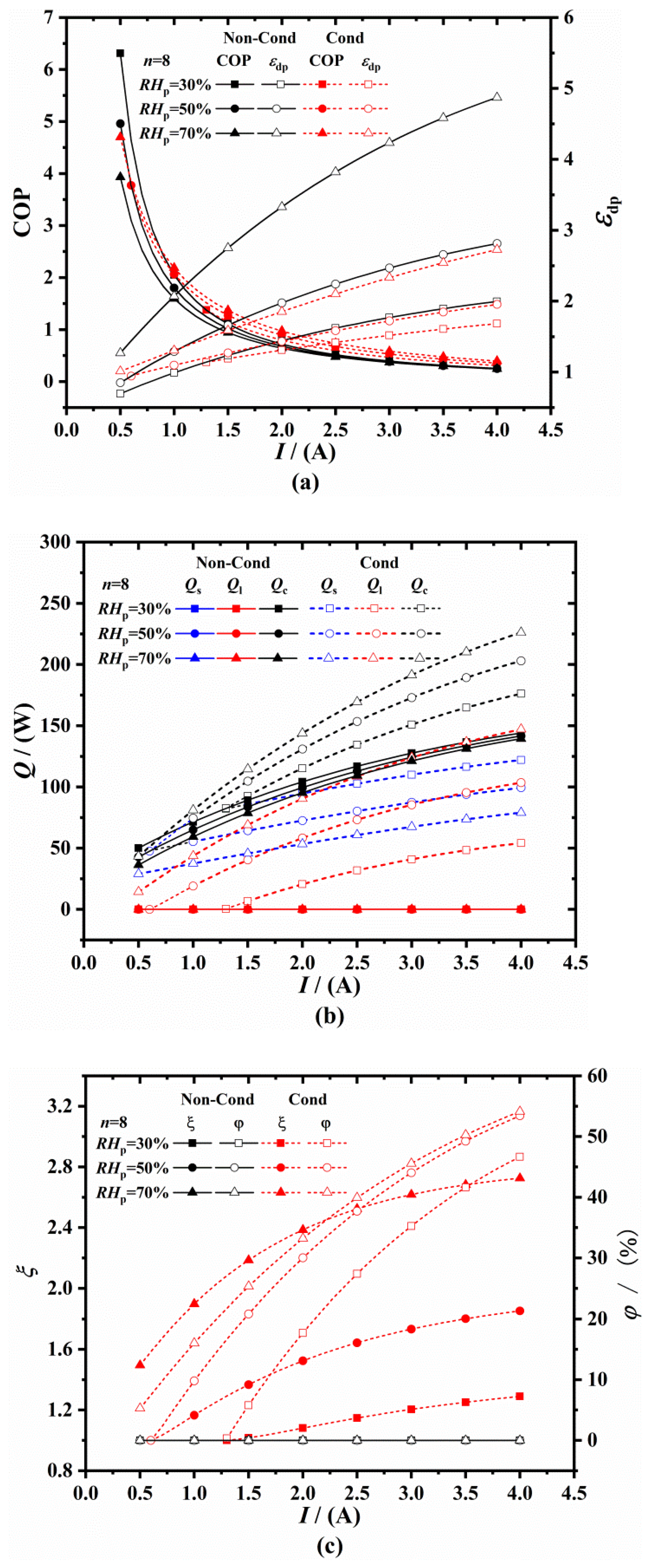
Figure 3a shows the variation trends of COP and
εdp with the electric current
I under non-condensation (i.e., Non-cond) and condensation (i.e., Cond) conditions. It can be seen that higher
I leads to higher
εdp, but lower COP. When the
RHp keeps as 30%, condensation occurs in dry channel when the current
I is higher than 1.3 A. When the
RHp is 50%, condensation occurs when the current
I is higher than 0.6 A. And when the
RHp is 70%, the condensation occurs when the current
I is lower than 0.5 A. To conclude, when the
RHp is higher, condensation is more likely to occur under lower
I. As is known that condensation occurs when the plate surface temperature of the primary air channel is decreased to lower than dew point temperature
Tp,dp. And when the inlet primary air temperature is constant, higher
RHp leads to higher
Tp,dp. Thus, the plate surface temperature leading to condensation could be reached under lower
I. Under both non-condensation and condensation state,
εdp increases with the
RHp increasing from 30% to 70%. However, with the increase of
RHp, COP under non-condensation state decreases and COP under condensation state increases. In addition, condensation from primary air would decrease
εdp up to 45.0% and increase the COP up to 62.2% by comparing the red lines under condensation conditions and black lines under non-condensation conditions. Once condensation occurs, latent heat transfer would appear and release heat to the plate, resulting in the increase of plate temperature, and then the increase of the outlet air temperature
Tp,o, which finally leads to the decrease of
εdp (
εdp = (
Tp,i −
Tp,o)/(
Tp,i −
Tpd,i)). As shown in
Figure 1b, when condensation occurs, the sensible heat transfer rate
Qs decreases, but the latent heat transfer rate
increases, thus, total heat transfer rate
Qc increases, which finally raises the value of COP (COP =
Qc/
N). Therefore, the latent heat transfer
plays a significant role in the heat and mass transfer process under condensation conditions. Moreover, when
I is higher, the
εdp under condensation state is much lower than those under non-condensation state. That is because that when
I is higher, the plate temperature is lower, the driving force of mass transfer is larger, and thus, more latent heat is released.
Figure 3c further shows that with considering condensation, both the enlargement ratio
ξ and dehumidification ratio
φ rise with the increases of
I and
RHp. The value of
ξ could even reach 2.73 when
I is 4 A and
RHp is 70%, which means the
from condensation is much more higher than
Qs. The dehumidification ratio
φ increases by more than 50% when
I is 4 A and the
RHp is 70%.
Figure 4 shows the variation trends of COP and
εdp with the TEC module number
n under different
RHp. It is shown that with the increase of
n, COP decrease, while
εdp increases. When
RHp is higher, condensation occurs under lower
n. With the
RHp as 30%, non-condensation state takes place with
n ranging from 8 to 25. With the
RHp as 50%,
εdp decreases by up to 7.5% and COP increases by up to 16.5% once condensation occurs when TEC module
n is higher than 12. As
RHp increases to 70%, condensation occurs throughout the range of TEC module
n, which leads to a remarkable decrease of
εdp by up to 26.1% and increase of COP by up to 58.8%.
Figure 5 displays the value of COP and
εdp with primary air inlet temperature
Tp,i under non-condensation and condensation states. With
n as 10 and
I as 0.5 A, condensation occurs when
Tp,i is higher than 39 °C. With
n as 15 and
I as 0.5 A, condensation occurs when
Tp,i is higher than 29 °C. With
n as 10 and
I as 1.0 A, condensation occurs when
Tp,i is lower than 25 °C. To conclude, when
n and
I are higher, condensation tends to occur under lower
Tp,i. When the
Tp,i increases from 25 °C to 45 °C, COP increases monotonously under all given conditions. The dew point effectivness
εdp increases with the
Tp,i growing under non-condensation state. However, under condensation state, there exists a maximum
εdp of 0.96 when
n is 10 and I is 0.5 A, a maximum
εdp of 1.01 when
n is 15 and I is 0.5, and a maximum
εdp of 1.16 when
n is 10 and
I is 1.0 A. In addition, in the given rages of
Tp,i, condensation from primary air would decrease
εdp by up to 24.5% and increase the COP by up to 31.2% by comparing the red lines under condensation conditions and black lines under non-condensation conditions.
Figure 6 presents the impact of inlet velocity of primary air
Vp on the COP and
εdp. COP increases and
εdp decreases with
Vp under given condition. The increase of
Vp could lead to a larger mass flow rate and a larger cooling capacity, resulting in the increase of COP. However, the increase of
Vp weakens the heat transfer between plate and primary air, leading to the decrease of the primary air outlet temperature, and then the decrease of
εdp. The condensation disappears when
Vp is larger than 2.5 m/s when
RHp is 50%. And when
RHp is 70%, the gape between
εdp curves under non-condensation and condensation states becomes more narrow with the increase of
Vp. The above results show that condensation is more likely occur under lower
Vp. In addition, in the given rages of
Vp, condensation from primary air would decrease
εdp by up to 25.8% and increase the COP by up to 49.8%.
Figure 7 illustrates variation trends of COP and
εdp with mass flow rate ratio
x of secondary air to primary air. It can be seen that with
RHp as 70%, condensation occurs throughout the given range of
x, with
RHp as 50%, condensation occurs when
x is greater than 0.5, and with
RHp as 30% non-condensation occurs. To conclude, when
RHp is higher, condensation is more likely to occur under lower
x.
εdp increases monotonously with
x under certain
RHp. In the given rages of
x, condensation from primary air would decrease
εdp up to 26.6% and increase the COP up to 36.9% by comparing the red lines under condensation conditions and black lines under non-condensation conditions. Moreover, a maximal COP exists with an optimal
x.


