
Performance of a Gasifier Reactor Prototype without a Blower Using Palm Oil Waste

 ,
,
Abstract
:1. Introduction
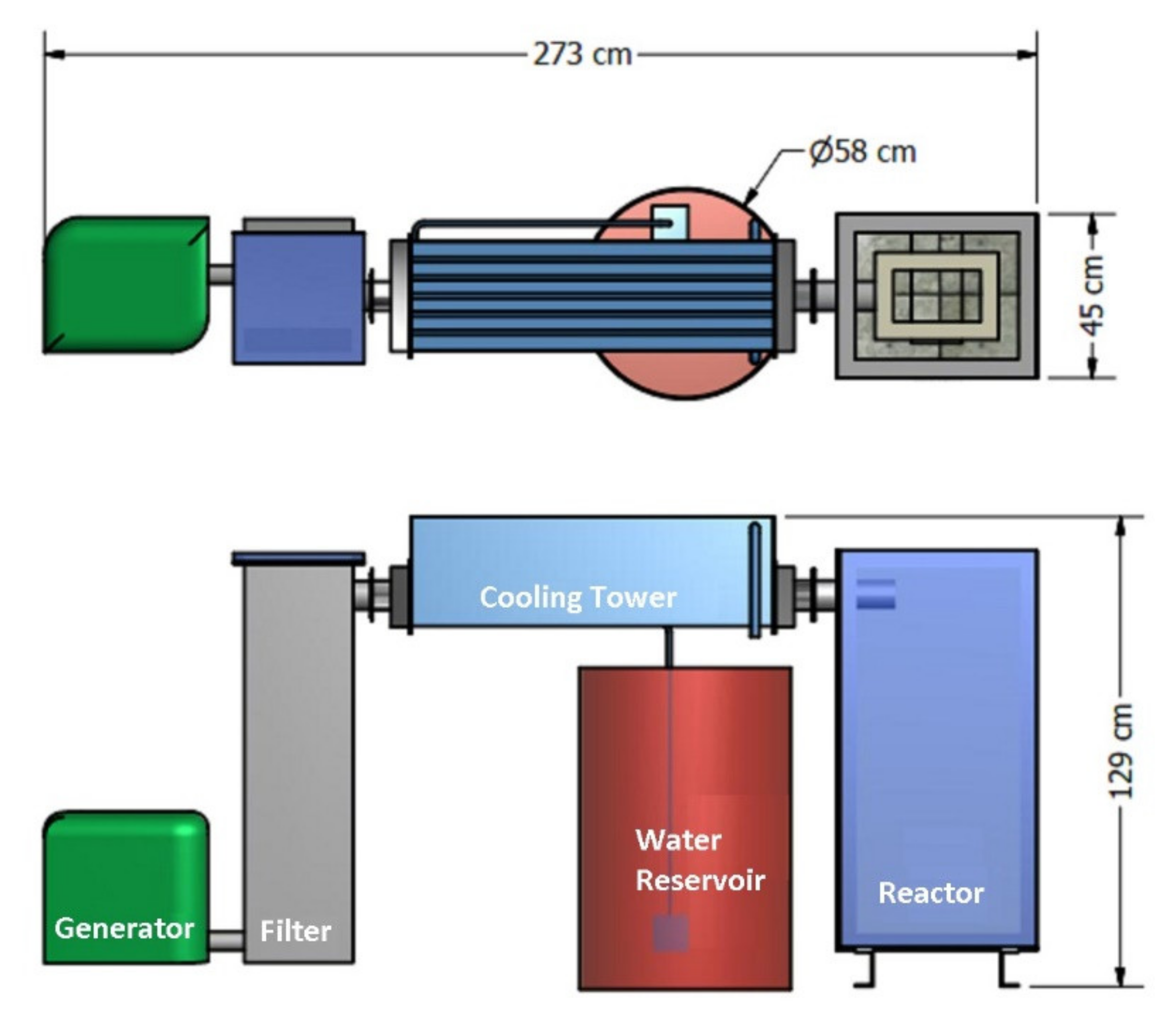
2. Reactor Prototype Design
2.1. Rate of Fuel Consumption
2.2. Reactor Dimension
2.3. Reactor Materials
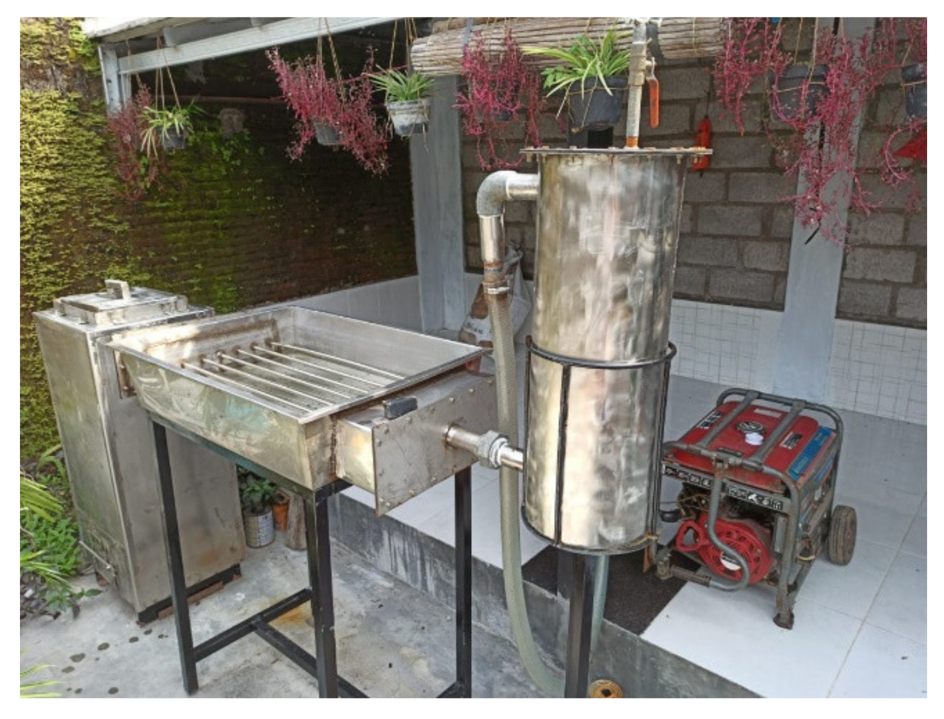
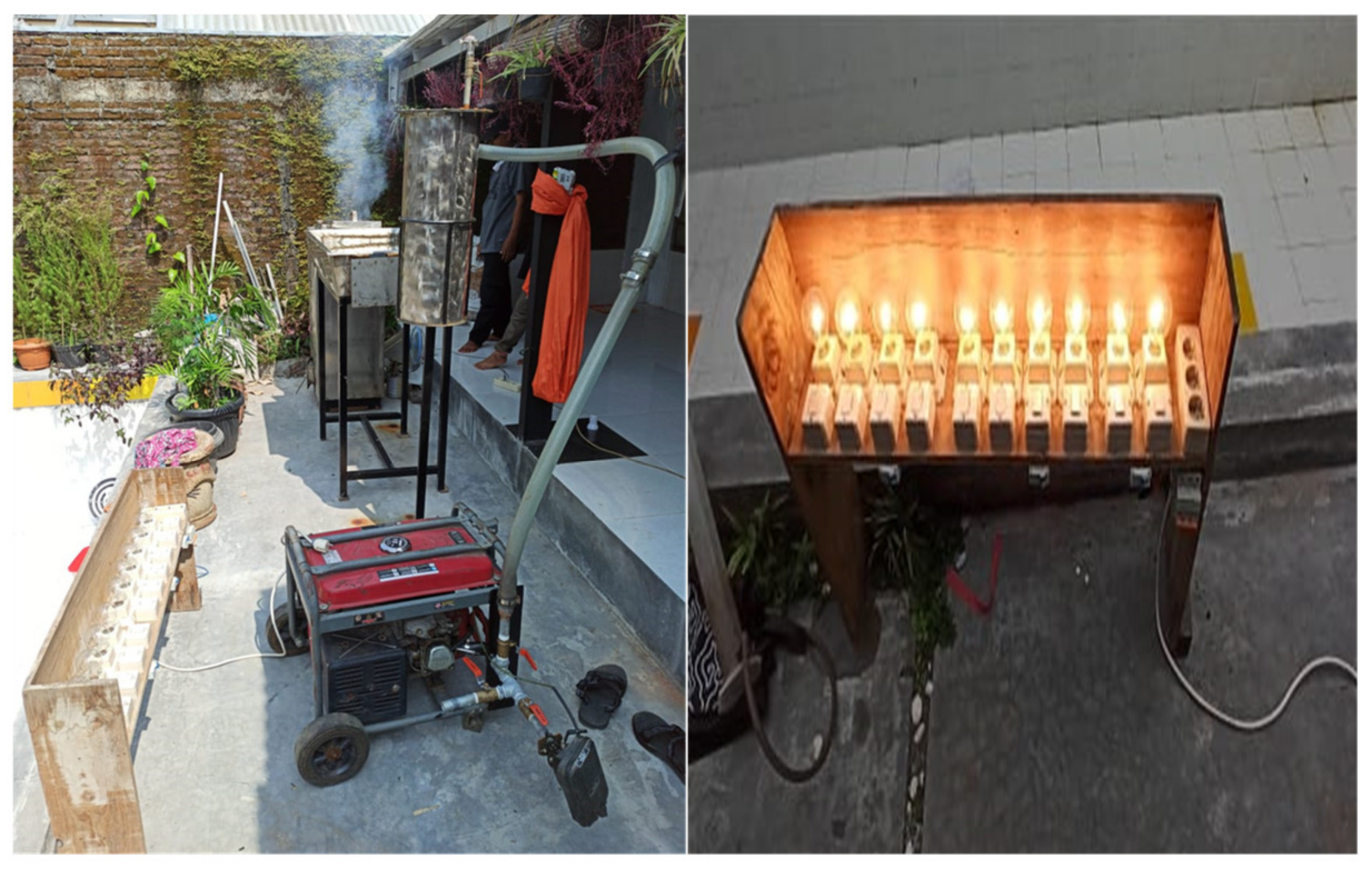
2.4. Prototype Performance Test
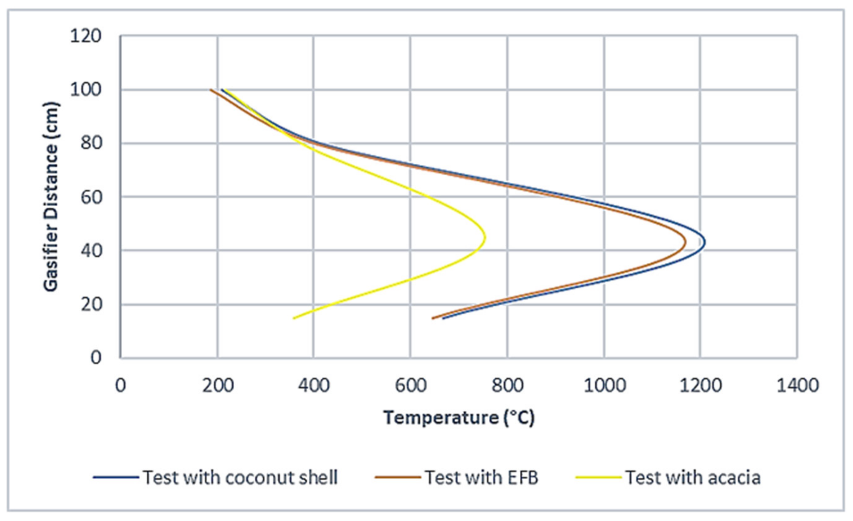
3. Test Results and Discussion
4. Conclusions
Author Contributions
Funding
Acknowledgments
Conflicts of Interest
Nomenclature
| FCR | Fuel Consumption Rate (kg/h) |
| HHV | High Heating Value (MJ/kg) |
| SGR | Specific Gasification Rate (kg/m2/h) |
| Output (kWh) | |
| Efficiency (%) | |
| Reactor Diameter (m) | |
| Cross-sectional area (cm2) | |
| Radius (cm) | |
| Reactor height (m) | |
| Operational time (h) | |
| Fuel density (kg/m3) |
References
- Wu, T.; Xu, D.L.; Yang, J.B. Multiple criteria performance modelling and impact assessment of renewable Energy systems—A literature review. In Renewable Energies Business Outlook 2050; Springer: Berlin/Heridelberg, Germany, 2018; pp. 1–15. [Google Scholar] [CrossRef]
- Susandi, A. The Changing of the Electric and Non Electric Energy Production and Technology Options for Emission Abatement on Indonesia. Available online: https://citeseerx.ist.psu.edu/viewdoc/download?doi=10.1.1.201.5771&rep=rep1&type=pdf (accessed on 17 November 2021).
- Kunaifi, K.; Veldhuis, A.J.; Reinders, A.H.M.E. The Electricity Grid in Indonesia: The Experiences of End-Users and Their Attitudes toward Solar Photovoltaics; Springer Nature: Cham, Switzerland, 2020. [Google Scholar]
- Yurnaidi, Z. Opportunities and Challenges of Renewable Energy and Distributed Generation Promotion for Rural Electrification in Indonesia. Green Energy Technol. 2010, 44, 102–107. [Google Scholar] [CrossRef]
- Kementerian ESDM. Jurnal Energi. 2016. Available online: https://www.esdm.go.id/assets/media/content/FIX2_Jurnal_Energi_Edisi_2_17112016(1).pdf (accessed on 17 November 2021).
- Van den Bergh, K.; Delarue, E. Quantifying CO2 abatement costs in the power sector. Energy Policy 2015, 80, 88–97. [Google Scholar] [CrossRef] [Green Version]
- Xiong, W.; Yang, Y.; Wang, Y.; Zhang, X. Marginal abatement cost curve for wind power in China: A provincial–level analysis. Energy Sci. Eng. 2016, 4, 245–255. [Google Scholar] [CrossRef] [Green Version]
- ESCAP. Energy Transition Pathways for the 2030 Agenda SDG7 Roadmap for Indonesia. 2020. Available online: https://www.unescap.org/resources/energy-transition-pathways-2030-agenda-sdg7-roadmap-indonesia (accessed on 17 November 2021).
- Veldhuis, A.J.; Reinders, A.H.M.E. Reviewing the potential and cost-effectiveness of off-grid PV systems in Indonesia on a provincial level. Renew. Sustain. Energy Rev. 2015, 52, 757–769. [Google Scholar] [CrossRef]
- Pacesila, M.; Burcea, S.G.; Colesca, S.E. Analysis of renewable energies in European Union. Renew. Sustain. Energy Rev. 2016, 56, 156–170. [Google Scholar] [CrossRef]
- Papilo, P.; Marimin; Hambali, E.; Sitanggang, I.S. Sustainability index assessment of palm oil-based bioenergy in Indonesia. J. Clean. Prod. 2018, 196, 808–820. [Google Scholar] [CrossRef]
- Yatim, P.; Ngan, S.L.; Lam, H.L. Sustainable Supply Chain: Feedstock Logistics Issues of Palm Oil Biomass Industry in Malaysia. In Transition towards 100% Renewable Energy; Springer: Cham, Switzerland, 2018; pp. 467–479. [Google Scholar] [CrossRef]
- Secretariat General National Energy Council. Indonesia Energy Outlook (IEO) 2019. 2019. Available online: https://www.esdm.go.id/assets/media/content/content-indonesia-energy-outlook-2019-english-version.pdf (accessed on 17 November 2021).
- Khatun, R.; Reza, M.I.H.; Moniruzzaman, M.; Yaakob, Z. Sustainable oil palm industry: The possibilities. Renew. Sustain. Energy Rev. 2017, 76, 608–619. [Google Scholar] [CrossRef]
- Effendi, S.; Azharuddin; Pramedian, G. Rancang Bangun Alat Gasifikasi Sistem Updraft Double Gas Outlet Berbahan bakar Biomassa (Tempurung Kelapa) dengan Pengaruh Laju Air Udara Pembakaran Terhadap Produk Syngas. J. Austenit. 2013, 5, 15–21. [Google Scholar]
- Selvakkumaran, S.; Limmeechokchai, B. Assessment of long-term low emission power generation in Sri Lanka and Thailand. Sustain. Energy Technol. Assess. 2017, 21, 121–141. [Google Scholar] [CrossRef]
- Basu, P. Biomass Gasification and Pyrolysis: Practical Design and Theory; Academic Press: Cambridge, MA, USA, 2013. [Google Scholar]
- Chand Malav, L.; Yadav, K.K.; Gupta, N.; Kumar, S.; Sharma, G.K.; Krishnan, S.; Rezania, S.; Kamyab, H.; Pham, Q.B.; Yadav, S.; et al. A review on municipal solid waste as a renewable source for waste-to-energy project in India: Current practices, challenges, and future opportunities. J. Clean. Prod. 2020, 277, 123227. [Google Scholar] [CrossRef]
- Perea-Moreno, M.A.; Samerón-Manzano, E.; Perea-Moreno, A.J. Biomass as renewable energy: Worldwide research trends. Sustainability 2019, 11, 863. [Google Scholar] [CrossRef] [Green Version]
- Jia, Y.; Wang, Y.; Zhang, Q.; Rong, H.; Liu, Y.; Xiao, B.; Guo, D.; Laghari, M.; Ruan, R. Gas-carrying enhances the combustion temperature of the biomass particles. Energy 2022, 239, 121956. [Google Scholar] [CrossRef]
- Pratiwi, I.; Studi, P.; Analisis, T.; Migas, L.; Akamigas, P. Rancang bangun alat gasifikasi biomassa (kayu karet) sistem updraft single gas outlet design of biomass gasification equipment (rubber wood) updraft single gas outlet system. J. Tek. Patra Akad. 2020, 11, 38–49. [Google Scholar]
- Pratoto, A.; Sutanto, A.; Praja, E.H.; Armenda, D. Rancang Bangun Tungku Gasifier Untuk Pemanfaatan Tandan Kelapa Sawit Sebagai Sumber Eenergi. In Proceedings of the Seminar Nasional Tahunan Teknik Mesin (SNTTM) ke-9, Palembang, Indonesia, 13–15 October 2010; pp. 13–15. [Google Scholar]
- Rinovianto, G. Karakteristik Gasifikasi Pada Updraft Double Gas Outlet; Universitas Indonesia: Kota Depok, Indonesia, 2012. [Google Scholar]
- Sanjaya, D.; Notosudjono, D.; Fiddiansyah, D.B. Perencanaan Gasifikasi Dari Limbah Kelapa Sawit Sebagai Energi Alternatif Di Ptpn Viii Cikasungka Kabupaten Bogor. Available online: http://jom.unpak.ac.id/index.php/teknikelektro/article/view/9771 (accessed on 17 November 2021).
- Siregar, K. Rancang Bangun Gasifier Downdraft dan Aplikasi PLT-Biomassa Kapasitas 50 kW Untuk Daerah Terisolasi Dari Jaringan Listrik PLN. In Proceedings of the Seminar Nasional Perteta-HIPI 2014, Online. 11–12 November 2014. [Google Scholar]


| Fuel Type | Testing without Load | Testing with Load | ||
|---|---|---|---|---|
| Fuel Consumption (mL) | Biomass Used (kg) | Fuel Consumption (mL) | Biomass Used (kg) | |
| Diesel | 350 | 0 | 800 | 0 |
| Diesel + acacia wood charcoal | 220 | 2.8 | 380 | 2.8 |
| Diesel + coconut shell charcoal | 200 | 3 | 350 | 3 |
| Diesel + EFB charcoal | 280 | 2 | 400 | 2 |
| Type of Fuel and Biomass | Calorific Value (kcal/kg) | Temperature (°C) |
|---|---|---|
| Diesel | 8591 | - |
| Acacia wood charcoal | 4800 | 754.2 |
| Coconut shell charcoal | 5700 | 1206 |
| EFB charcoal | 3353 | 1166 |
| Fuel Type | Testing without Load | Testing with Load |
|---|---|---|
| Cost of Consumption (Rp) | Cost of Consumption (Rp) | |
| Diesel | 3290 | 7520 |
| Diesel + acacia wood | 16,068 | 17,572 |
| Diesel + coconut shell | 22,880 | 24,290 |
| Diesel + EFB | 2632 | 3760 |
Publisher’s Note: MDPI stays neutral with regard to jurisdictional claims in published maps and institutional affiliations. |
© 2021 by the authors. Licensee MDPI, Basel, Switzerland. This article is an open access article distributed under the terms and conditions of the Creative Commons Attribution (CC BY) license (https://creativecommons.org/licenses/by/4.0/).
Share and Cite
Nur Chairat, A.S.; Antono, V.; Prayudi, P.; Nurhasanah, R.; Batih, H. Performance of a Gasifier Reactor Prototype without a Blower Using Palm Oil Waste. Processes 2021, 9, 2094. https://doi.org/10.3390/pr9112094
Nur Chairat AS, Antono V, Prayudi P, Nurhasanah R, Batih H. Performance of a Gasifier Reactor Prototype without a Blower Using Palm Oil Waste. Processes. 2021; 9(11):2094. https://doi.org/10.3390/pr9112094
Chicago/Turabian StyleNur Chairat, Arief Suardi, Vendy Antono, Prayudi Prayudi, Roswati Nurhasanah, and Hakimul Batih. 2021. "Performance of a Gasifier Reactor Prototype without a Blower Using Palm Oil Waste" Processes 9, no. 11: 2094. https://doi.org/10.3390/pr9112094
APA StyleNur Chairat, A. S., Antono, V., Prayudi, P., Nurhasanah, R., & Batih, H. (2021). Performance of a Gasifier Reactor Prototype without a Blower Using Palm Oil Waste. Processes, 9(11), 2094. https://doi.org/10.3390/pr9112094