Abstract
This paper proposes a robust optimization algorithm customized for the optimal design of electric machines. The proposed algorithm, termed “robust explorative particle swarm optimization” (RePSO), is a hybrid algorithm that affords high accuracy and a high search speed when determining robust optimal solutions. To ensure the robustness of the determined optimal solution, RePSO employs the rate of change of the cost function. When this rate is high, the cost function appears as a steep curve, indicating low robustness; in contrast, when the rate is low, the cost function takes the form of a gradual curve, indicating high robustness. For verification, the performance of the proposed algorithm was compared with those of the conventional methods of robust particle swarm optimization and explorative particle swarm optimization with a Gaussian basis test function. The target performance of the traction motor for the optimal design was derived using a simulation of vehicle driving performance. Based on the simulation results, the target performance of the traction motor requires a maximum torque and power of 294 Nm and 88 kW, respectively. The base model, an 8-pole 72-slot permanent magnet synchronous machine, was designed considering the target performance. Accordingly, an optimal design was realized using the proposed algorithm. The cost function for this optimal design was selected such that the torque ripple, total harmonic distortion of back-electromotive force, and cogging torque were minimized. Finally, experiments were performed on the manufactured optimal model. The robustness and effectiveness of the proposed algorithm were validated by comparing the analytical and experimental results.
1. Introduction
Recently, owing to the strengthening of environmental regulations worldwide, there has been a significant increase in the electrification of vehicles. Vehicle manufacturers around the world are launching hybrid electric vehicles, fuel cell electric vehicles, and electric vehicles (EVs), along with internal combustion engine vehicles, in order to meet environmental regulations. This has also led to the active research and development of traction motors [1,2,3].
The traction motor is the primary component in an EV; therefore, it is necessary to ensure the safety and performance of this component. The analysis methods used for designing a motor can be largely divided into methods based on magnetic equivalent circuits (MECs) and those based on finite element analysis (FEA). Although MECs enable faster analyses, nonlinear magnetic saturation characteristics cannot be reflected when using this method. In contrast, when using FEA, although the analysis speed is slow, nonlinear magnet saturation characteristics can be reflected. Therefore, EV traction motors, which necessitate excellent nonlinear magnetic saturation characteristics, are primarily designed using FEA [4,5,6,7].
In this study, we propose an optimization algorithm for designing traction motors for EVs. The optimal design of an electric machine is characterized by a multi-modal function with high nonlinearity. In particular, if the optimal design is not robust, a significant deviation in performance is observed depending on the manufacturing tolerances. In addition, as the FEA-based optimal design, which reflects magnetic saturation characteristics, involves time-consuming analyses, it is necessary to develop an algorithm with a high search speed [8,9].
The optimization algorithm proposed herein is a novel algorithm that enhances robustness through the addition of a new method to the memetic algorithm that combines particle swarm optimization (PSO) and mesh adaptive direct search (MADS). The performance of the proposed algorithm was compared with those of the conventional algorithms through a test function. The proposed approach was also applied to the optimal design of an EV traction motor. In addition, to verify the optimal design thus obtained, an optimally designed model was manufactured and tested. By comparing the experimental and analytical results, we verified the effectiveness of the proposed algorithm.
2. Robust Explorative Particle Swarm Optimization
2.1. Conventional PSO
PSO, proposed by Kennedy and Eberhart [10], is an algorithm that searches for optimal solutions by simulating the behavior of a flock of birds. It is widely used in engineering applications owing to its excellent capability of searching for global optimal solutions.
The equations for PSO can be expressed as follows:
where ω is the inertia weight; v is the velocity; c1 and c2 are acceleration coefficients; rand1 and rand2 are two uniformly distributed random numbers generated within [0, 1]; pBest is the personal best point for the i-th particle; and gBest is the global best point.
2.2. Explorative PSO
Equations (1) and (2) describe the conventional PSO. However, in this study, explorative PSO (ePSO), an improved particle swarm optimization to reinforce search speed for global optimum, was used as the base algorithm to achieve a high search speed and quick convergence. Furthermore, ePSO strategically uses PSO and MADS by dividing the search stage. In the explorative search stage, ePSO adopts PSO for a wide search area, and ePSO searches the candidate areas where optimal solutions exist and assigns them to clusters. The equations for ePSO are as follows [11]:
where nBest represents the neighboring best point, which is different from pBest as used in conventional PSO. When nBest is determined, the other neighboring particles update their velocity and direction and converge to this nBest position. The converged nBest positions are identified as clusters, and MADS is used for an exploitative search of the clusters. The flowchart of ePSO is presented in Figure 1 [11].
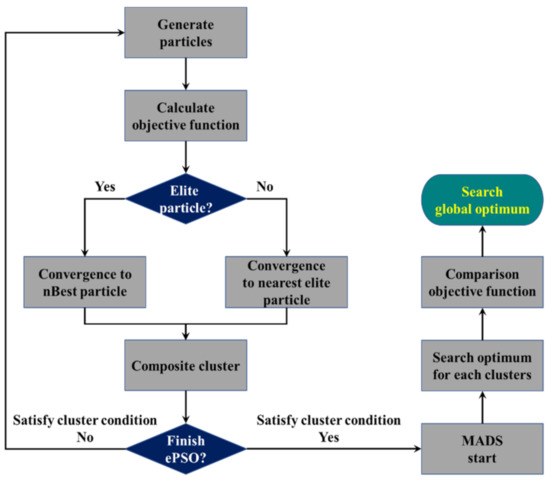
Figure 1.
The flow chart of ePSO.
In the exploitative search stage, ePSO uses MADS to search for a nearby optimal solution. MADS, which is a type of heuristic algorithm, is an iterative search optimization algorithm that quickly searches for local optimal solutions [12].
The equations of MADS used for the exploitative search are
where Mk and pk denote the mesh and frame in the k-th iteration, respectively; D is a positive spanning set; NnD is the number of search directions; Sk is the set of points where the cost function is evaluated at the k-th iteration; d is the frame direction in the k-th positive spanning set Dk; is the mesh size parameter, which scales D to expand or contract depending on the success or failure of previous searches [13]. Examples of MADS reference frames are shown in Figure 2.
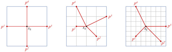
Figure 2.
Examples of MADS reference frames.
2.3. Proposed Algorithm for Searching Robust Optimum
The proposed novel algorithm is named robust explorative particle swarm optimization (RePSO), and it is based on the mechanism of ePSO. The proposed algorithm offers two advantages: high search speed and the ability to search for robust optimal solutions. RePSO is a method that ensures robustness, calculates the rate of change of the cost function in the MADS stage on ePSO, and determines the robustness by analyzing the trend of the rate of change of the cost function. As shown in Figure 3, when the rate of change of the cost function is low, the curve of the cost function tends to be gradual. In contrast, when the rate of change is high, the curve of the cost function tends to be steep.
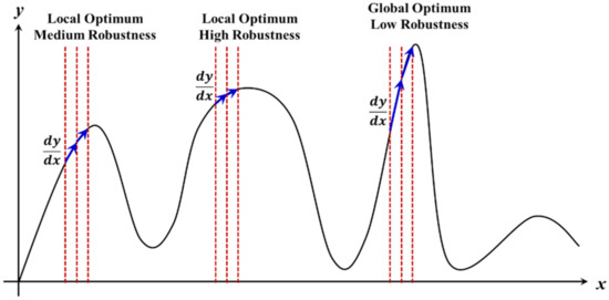
Figure 3.
Concept for discrimination of robust solution.
Therefore, based on the calculated rate of change, RePSO uses a discriminant to choose a robust optimal solution from the clusters. The discriminant of the proposed algorithm is expressed as follows:
where CF is the difference solution set of MADS beginning at j-th cluster, and xi is the cost value of i-th iteration.
From Equations (7) and (8), the robust solution is determined when the difference of the cost value is minimum. The flowchart of RePSO is shown in Figure 4.
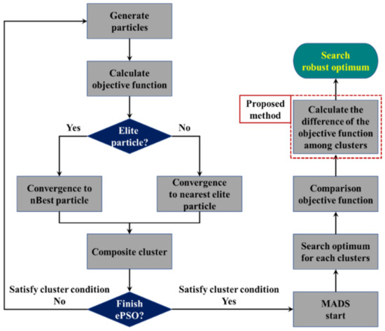
Figure 4.
The flow chart of RePSO.
3. Numerical Validation of the Proposed Algorithm
The performance of RePSO was validated using a Gaussian basis function. In addition, the performance of RePSO was compared with those of RPSO, being an improved particle swarm optimization to emphasize robustness, and ePSO. The equations of the Gaussian basis function are expressed below [14]:
The general definition of the Gaussian basis function is
where β is the amplitude, γ is the center, σ is the width of the basic function, and m is the number of the entire basis function.
The test function is expressed as
The global optimum of the test function is located at (3, 4), and the robust solution is located at (3, 1). The 2D and 3D plots of the test function are depicted in Figure 5.
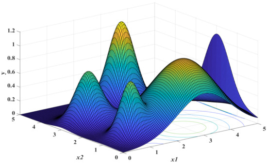
Figure 5.
3D plot of the test function.
To verify the performance under identical conditions, the same parameter values were used for all three algorithms. The values of the parameters used are listed in Table 1 [11].

Table 1.
Essential PSO variables for the numerical test.
Each independent run was performed 10 times, and the test results are shown in Table 2 [11].
Table 2.
Test results of the test function.
In Figure 6, the change rate of the cost function at global optimum and robust optimum are shown. In the robust optimum, the change rate of the cost function is smaller than that for the global optimum.
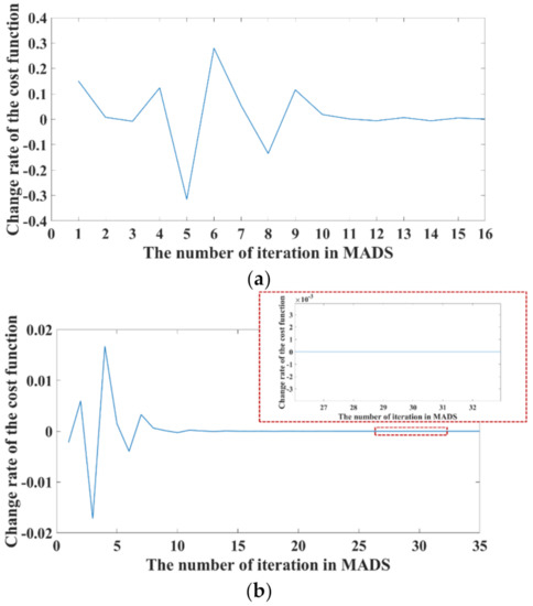
Figure 6.
Comparison of change rate at global optimum and robust optimum: (a) change rate of the cost function at global optimum; (b) change rate of the cost function at robust optimum.
The results indicate that the average number of function calls for RPSO was 4172.4. In contrast, for ePSO and RePSO, the average number of function calls were 763.2 and 796.2, respectively. This shows that ePSO and RePSO exhibit superior performance compared to RPSO in terms of the solution searching speed. In addition, RePSO achieved the best result when searching for a robust solution. RePSO searched for the robust solution nine times, whereas RPSO and ePSO searched for the robust solution eight and three times, respectively. This result verifies the superiority of RePSO.
4. Derivation of Performance Specifications
The driving performance of a vehicle was simulated to derive the performance specifications of the target traction motor. The simulation was performed based on the equations listed below, and the relationship between the vehicle and each driving load is illustrated in Figure 7.
Torque of drive shaft: motor torque × reduction ratio
Speed of drive shaft: motor speed/reduction ratio
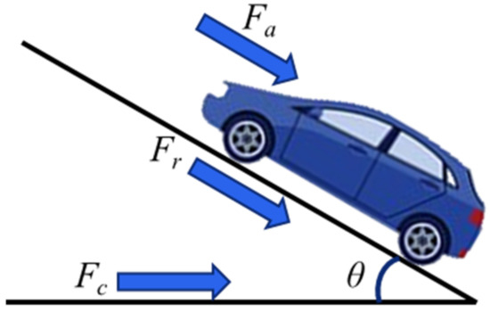
Figure 7.
Relation between vehicle and driving loads.
Here, GVW is the gross vehicle weight; Cr and Cd are the coefficients of rolling resistance and aero-drag resistance, respectively; g is the acceleration due to gravity; θ is the climbing angle; ρ is the air density; A is the frontal area of the vehicle; and ve is the vehicle velocity. [15,16]. If the calculated drive shaft torque and speed of the vehicle are greater than the sum of all the driving loads, the vehicle is able to be driven.
The curves of the vehicle driving performance are shown in Figure 8 below.
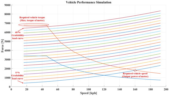
Figure 8.
Vehicle driving performance curves.
A C-segment class EV was selected as the target vehicle. The specifications and target performance of this vehicle are presented in Table 3 and Table 4, respectively.
Table 3.
Input parameters for vehicle performance simulation.
Table 4.
Vehicle target performance.
The target performance of the traction motor, derived from the driving performance simulation, is shown in Figure 9.
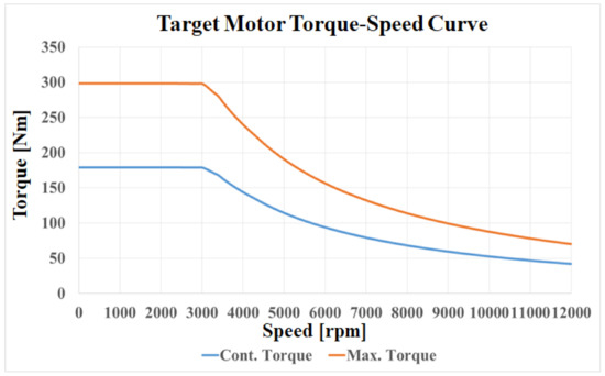
Figure 9.
Target motor torque-speed curve.
From the simulation results, the required maximum torque and maximum power of the traction motor were determined as 294 Nm and 88 kW, respectively. The base and maximum speeds of the traction motor were found to be 2850 rpm and 12,000 rpm, respectively.
5. Design of the Base Model
Based on the target specifications derived from the driving performance simulation, a base model of the traction motor was designed. The specifications of the base model are listed in Table 5.
Table 5.
Specifications of the designed motor.
As the traction motor of an EV uses a reducer, the high-speed operation of the traction motor is required to satisfy the maximum speed of the vehicle. Therefore, an interior permanent magnet synchronous machine (IPMSM) was employed as the traction motor. The number of poles was set as eight considering the inverter switching frequency; 72 slots were chosen, which is the maximum number of slots that can be manufactured. The topology of the base model is depicted in Figure 10 [17].
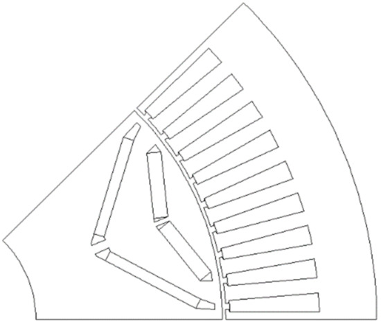
Figure 10.
Topology of the base model.
The total harmonic distortion (THD) of the back-electromotive force (back-EMF) and the peak-to-peak cogging torque were confirmed under the no-load condition. The high THD of the back-EMF could overcome the control stability of the inverter, and the high cogging torque resulted in vibration and noise in the traction motor. The THD of the back-EMF and cogging torque of the base model were 4.78% and 4.10 Nm, respectively. The waveforms of the back-EMF and cogging torque are shown in Figure 11.
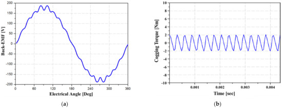
Figure 11.
Design result of the base model in no-load condition: (a) back-EMF waveform; (b) cogging torque waveform.
The target specifications, average torque, and torque ripple, which causes noise and vibration, were confirmed under the loaded condition. The average torque was found to be 295.33 Nm, which satisfies the target specification, and the torque ripple was 5.93%. The torque waveform and the contour of magnetic flux density are presented in Figure 12.
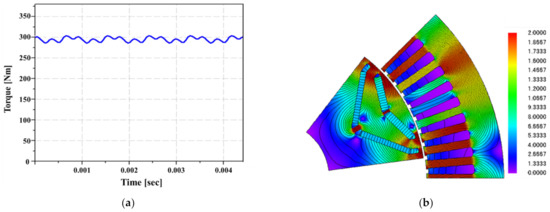
Figure 12.
Design result of the base model in load condition: (a) torque waveform; (b) magnetic flux density and flux line plot.
6. Optimal Design Using RePSO
The optimal design of the base model was realized using RePSO. First, the objective function and constraint condition were decided to create the optimal design using the optimization algorithm. The aim of the objective function was to minimize the torque ripple, THD of the back-EMF, and cogging torque. The reason that the torque ripple, cogging torque, and THD of the back-EMF were chosen for the objective function is that those are the main factors generating noise and vibration in the traction motor. Since noise and vibration cause discomfort to passengers, these should be minimized in designing a vehicle traction motor.
The average torque was set as the constraint because it is necessary to achieve the average torque required when designing an IPMSM. The objective function is expressed as follows [18,19,20]:
where λ, μ, and ν are the weights of each parameter. In this study, λ, μ, and ν were set as 0.4, 0.2, and 0.4, respectively.
Objective function = λTHD + μTripple + νTcogging
The constraint condition, i.e., average torque, was set to be above 294.8 Nm. A total of 15 variables related to minimizing the objective function were used to obtain the optimal design; the details are shown in Figure 13. As the mechanical stress of the rotor is necessarily secured, the distances between the center posts and from the bridge to the outer diameter of the rotor are constrained.
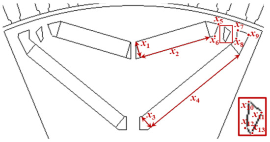
Figure 13.
Design variables of the optimal model.
A flowchart of the optimal design is presented in Figure 14. The optimal design obtained via the optimization algorithm is implemented using an automation code in combination with FEA.
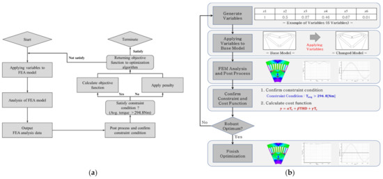
Figure 14.
The flowchart of optimal design with optimization algorithm and FEM: (a) flow chart of optimization with optimization algorithm; (b) flow chart of traction motor optimization with FEM.
The algorithm generates random values for the topology variables of the target model. These variables alter the topology of the target model, which is then analyzed using FEA. Based on the analysis results, the post-processed average torque is compared with the constraint condition. If the average torque satisfies the constraint condition, the objective function is calculated and returned to the algorithm. However, if the average torque does not satisfy the constraint condition, the objective function is not calculated and is ignored by the algorithm. Owing to the mechanism of the optimization algorithm, a topology with a better objective function is derived after multiple iterations, and the optimization ceases when there is no further improvement in the objective function [21].
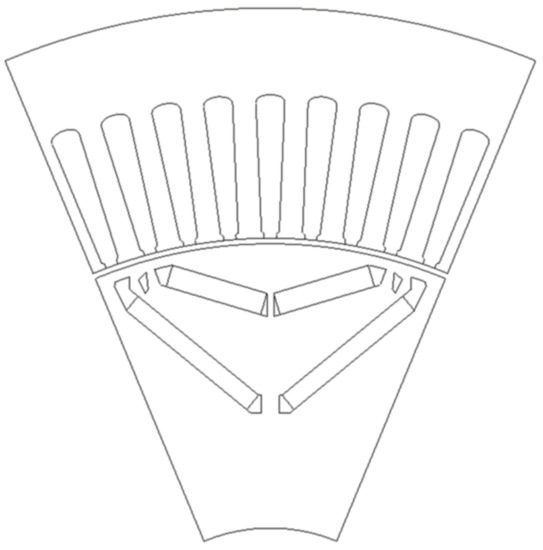
Figure 15.
Topology of the optimal model.
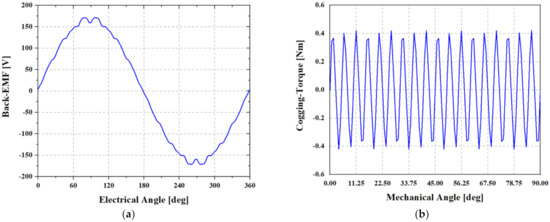
Figure 16.
Optimal design result in no-load condition: (a) back-EMF waveform; (b) cogging torque waveform.
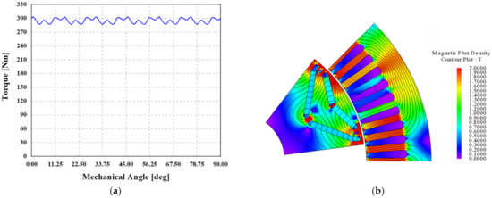
Figure 17.
Optimal design result in load condition: (a) torque waveform; (b) magnetic flux density and flux line.
The THD of the back-EMF, which has a weight (λ) of 0.4 in the objective function, is decreased by 2.1% (from 4.58% in the improved model to 2.68% in the optimal model). The torque ripple, which has a weight (μ) of 0.2 in the objective function, is reduced by 0.37% (from 5.93% in the improved model to 5.56% in the optimal model). The cogging torque, with a weight (ν) of 0.4, decreases by 3.26 Nm (from 4.10 Nm in the improved model to 0.84 Nm in the optimal model).
7. Manufacturing and Experiment
The performance of the optimal designed model was validated via experiments on a manufactured prototype. In order to realize a high-efficiency and high-performance, 0.27mm magnetic steel sheet and 47 grade NdFe-B permanent magnet were used. The winding method is distributed winding, and it is wound using a reel that bundles the thin wires in order to increase the winding fill factor and decrease the skin and proximity effect of the copper.
The topology of the prototype is presented in Figure 18a, which depicts the rotor topology of the prototype model, while Figure 18b shows the stator topology along with its winding. The experimental environment is presented in Figure 19.
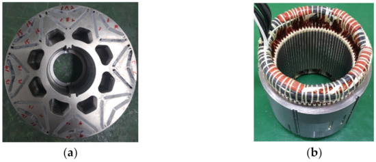
Figure 18.
Topologies of the manufactured model: (a) rotor; (b) stator.
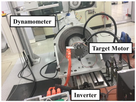
Figure 19.
The experimental environment.
First, the back-EMF was measured using an oscilloscope. The waveform of the line-to-line back-EMF is presented in Figure 20.
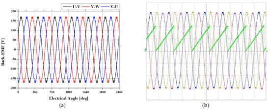
Figure 20.
Optimal design result in load condition: (a) torque waveform; (b) magnetic flux density and flux line.
On measuring the back-EMF of the motor, a root mean square value of 43.97 V was obtained; the analyses of the model using FEA yielded a value of 42.66 V. The waveforms exhibited similar shapes, and an error of 2.98% was observed between the analytical and experimental values, indicating that the prototype model was manufactured with robustness.
Next, an experiment was conducted to evaluate the performance of the motor. The motor performance was verified by comparing the T–N curves obtained using analytical and experimental data. A comparison of the T–N curves is presented in Figure 21. Based on this comparison, it was found that the analytical and experimental data were well matched.
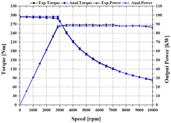
Figure 21.
The experimental environment.
Finally, the efficiency of the motor was evaluated. In this test, an efficiency map was prepared using the efficiency data for each operating point, and these efficiency maps were subsequently compared. The maximum efficiency point of the experimental data was 78.63 Nm at 4275 rpm; the efficiency at this point was 97.13%. Moreover, the maximum efficiency point of the analytical data was 60 Nm at 5000 rpm; the efficiency at this point was 98.02%. A comparison of the efficiency maps is presented in Figure 22.
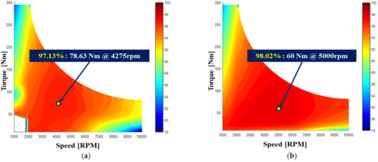
Figure 22.
The comparison of the efficiency map: (a) experimental result; (b) analysis result.
8. Conclusions
A novel robust optimization algorithm for electric machines was developed in this study. The proposed hybrid algorithm combines PSO and MADS. It performs explorative searches using PSO and exploitative searches using MADS in order to quickly determine the optimal solutions. It also searches for robust solutions using a discriminant by calculating the rate of change of the cost function when performing MADS.
First, the performance of the proposed algorithm was verified using a test function. The results confirmed that its search speed and ability to search for robust optimal solutions are superior to those of the conventional algorithms.
Second, the driving performance of a vehicle was simulated to determine the target specifications of the traction motor for the target EV. The target specifications of the traction motor were found to be a maximum power of 88 kW and a maximum torque of 294 Nm.
Third, a base model for the optimal design was realized using an 8-pole 72-slot IPMSM. As a result of the design, the base model had an average torque of 294.8 Nm, THD of the back-eff of 4.78%, cogging torque of 4.10 Nm, and torque ripple of 5.93%.
Fourth, an optimal design was created by applying the proposed algorithm to the base model. Owing to the optimal design, the THD of the back-EMF, which had a weight (λ) of 0.4 in the objective function, decreased by 2.1% (from 4.58% in the base model to 2.68% in the optimal model). The torque ripple, with a weight (μ) of 0.2 in the objective function, was reduced by 0.37% (from 5.93% in the base model to 5.56% in the optimal model). Moreover, the cogging torque, with a weight (ν) of 0.4, decreased by 3.26 Nm (from 4.10 Nm in the base model to 0.84 Nm in the optimal model).
Finally, the optimal model was manufactured and tested to verify the effectiveness of the optimal design. It was found that the optimal model yielded results that were similar to the experimental results, thereby verifying the effectiveness of the proposed algorithm.
Author Contributions
Conceptualization, J.-H.L. and S.-Y.J.; methodology, J.-H.L.; software, J.-H.L.; validation, J.-H.L., W.-J.K. and S.-Y.J.; formal analysis, J.-H.L.; investigation, J.-H.L.; resources, J.-H.L. and W.-J.K.; data curation, J.-H.L.; writing—original draft preparation, J.-H.L.; writing—review and editing, J.-H.L., W.-J.K. and S.-Y.J.; visualization, J.-H.L.; supervision, S.-Y.J.; project administration, W.-J.K. and S.-Y.J.; funding acquisition, W.-J.K. and S.-Y.J. All authors have read and agreed to the published version of the manuscript.
Funding
This research received no external funding.
Institutional Review Board Statement
Not applicable.
Informed Consent Statement
Not applicable.
Data Availability Statement
Not applicable.
Acknowledgments
This work was supported by the Technology Innovation Program (or Industrial Strategic Technology Development Program) (20011866, Development of 400 kW class electric drive system technology based on multiple motors for the electrified powertrain of heavy duty fuel cell electric trucks) funded By the Ministry of Trade, Industry & Energy (MOTIE, Korea).
Conflicts of Interest
The authors declare no conflict of interest.
References
- Liu, Q.; Chen, H.; Hu, Y.; Sun, P.; Li, J. Modeling and Control of the Fuel Injection System for Rail Pressure Regulation in GDI Engine. IEEE/ASME Trans. Mechatron. 2014, 19, 1501–1513. [Google Scholar]
- Bang, Y.; Yoon, M. 3-Speed Transmission Using Dual Motors and One-Way Clutches. IEEE/ASME Trans. Mechatron. 2016, 21, 412–418. [Google Scholar] [CrossRef]
- Jiang, K.; Yan, F.; Zhang, H. Hydrothermal Aging Factor Estimation for Two-Cell Diesel-Engine SCR System via a Dual Time-Scale Unscented Kalman Filter. IEEE Trans. Ind. Electron. 2020, 67, 442–450. [Google Scholar] [CrossRef]
- Lim, J.; Lee, K. Distributed Multilevel Current Models for Design Analysis of Electromagnetic Actuators. IEEE/ASME Trans. Mechatron. 2015, 20, 2413–2424. [Google Scholar] [CrossRef]
- Ramirez-Laboreo, E.; Rose, M.G.L.; Sagues, C. Hybrid Dynamical Model for Reluctance Actuators Including Saturation, Hysteresis, and Eddy Currents. IEEE/ASME Trans. Mechatron. 2019, 24, 1396–1406. [Google Scholar] [CrossRef]
- Saneie, H.; Hasiri-Gheidari, Z.; Tootoonchian, F. Design-Oriented Modelling of Axial-Flux Permanent-Magnet Machines. IEEE Trans. Ind. Electron. 2018, 65, 4322–4330. [Google Scholar] [CrossRef]
- Wu, S.; Zhao, X.; Jiao, Z.; Luk, P.C.; Jiu, C. Multi-Objective Optimal Design of a Toroidally Wound Radial-Flux Halbach Permanent Magnet Array Limited Angle Torque Motor. IEEE Trans. Ind. Electron. 2017, 64, 2962–2971. [Google Scholar] [CrossRef] [Green Version]
- Chen, H.; Yan, W.; Gu, J.J.; Sun, M. Multiobjective Optimization Design of a Switched Reluctance Motor for Low-Speed Electric Vehicles with a Taguchi-CSO Algorithm. IEEE/ASME Trans. Mechatron. 2018, 23, 1762–1774. [Google Scholar] [CrossRef]
- Liu, G.; Wang, Y.; Chen, Q.; Xu, G.; Song, C. Multiobjective Deterministic and Robust Optimization Design of a New Spoke-Type Permanent Magnet Machine for the Improvement of Torque Performance. IEEE Trans. Ind. Electron. 2020, 67, 10202–10212. [Google Scholar] [CrossRef]
- Kennedy, J.; Eberhart, R. Particle Swarm Optimization. Proc. Int. Conf. Neural Netw. 1995, 4, 1942–1948. [Google Scholar] [CrossRef]
- Lee, J.; Kim, J.; Song, J.; Kim, Y.; Jung, S. A Novel Memetic Algorithm Using Modified Particle Swarm Optimization and Mesh Adaptive Direct Search for PMSM Design. IEEE Trans. Magn. 2016, 52, 7001604. [Google Scholar] [CrossRef]
- Audet, C.; Dennis, J.E. Mesh adaptive direct search algorithms for constrained optimization. SIAM J. Optim. 2006, 17, 188–217. [Google Scholar] [CrossRef] [Green Version]
- Son, B.; Park, G.; Kim, J.; Kim, Y.; Jung, S. Interstellar Search Method with Mesh Adaptive Direct Search for Optimal Design of Brushless DC Motor. IEEE Trans. Magn. 2016, 52, 8201004. [Google Scholar] [CrossRef]
- Luan, F.; Choi, J.; Jung, H. A Particle Swarm Optimization Algorithm with Novel Expected Fitness Evaluation for Robust Optimization Problems. IEEE Trans. Magn. 2012, 48, 331–334. [Google Scholar] [CrossRef]
- Yi, Z.; Bauer, P.H. Adaptive Multiresolution Energy Consumption Prediction for Electric Vehicles. IEEE Trans. Veh. Technol. 2017, 66, 10515–10525. [Google Scholar] [CrossRef]
- Kivekas, K.; Lajunen, A.; Baldi, F.; Vepsalainen, J.; Tammi, K. Reucing the Energy Consumption of Electric Buses with Design Choices and Predictive Driving. IEEE Trans. Veh. Technol. 2019, 68, 11409–11419. [Google Scholar] [CrossRef]
- Do, T.; Choi, H.; Jung, J. Nonlinear Optimal DTC Design and Stability Analysis for Interior Permanent Magnet Synchronous Motor Drives. IEEE/ASME Trans. Mechatron. 2015, 20, 2716–2725. [Google Scholar] [CrossRef]
- Li, J.; Wang, K. A Novel Spoke-Type PM Machine Employing Asymmetric Modular Consequent-Pole Rotor. IEEE/ASME Trans. Mechatron. 2019, 24, 2182–2192. [Google Scholar] [CrossRef]
- Song, J.; Dong, F.; Zhao, J.; Wang, H.; He, Z.; Wang, L. An Efficient Multiobjective Design Optimization Method for a PMSLM Based on an Extreme Learning Machine. IEEE Trans. Ind. Electron. 2019, 66, 1001–1011. [Google Scholar] [CrossRef]
- Seo, M.; Lee, T.; Kim, J.; Kim, Y.; Jung, S. Principal Component Optimization with Mesh Adaptive Direct Search for Optimal Design of IPMSM. IEEE Trans. Magn. 2017, 53, 1–4. [Google Scholar] [CrossRef]
- Lee, J.; Song, S.; Kim, D.; Kim, J.; Kim, Y.; Jung, S. Particle Swarm Optimization Algorithm with Intelligent Particle Number Control for Optimal Design of Electric machines. IEEE Trans. Ind. Electron. 2018, 65, 1791–1798. [Google Scholar] [CrossRef]
Publisher’s Note: MDPI stays neutral with regard to jurisdictional claims in published maps and institutional affiliations. |
© 2021 by the authors. Licensee MDPI, Basel, Switzerland. This article is an open access article distributed under the terms and conditions of the Creative Commons Attribution (CC BY) license (https://creativecommons.org/licenses/by/4.0/).