1. Introduction
As the need for more efficient ways of condensation heat transfer grows, so does research interest in superhydrophobic (SHPhob) surfaces. In comparison to conventional dropwise condensation, jumping-droplet condensation can occur on SHPhob surfaces, which is reported to increase heat flux up to 25% [
1]. This may be beneficial for numerous systems, including heat exchangers, heating, ventilation and air conditioning, electronics cooling, heat pipes, thermal diodes, heat pumps and many others [
1,
2,
3].
A variety of fabrication techniques exist to make a SHPhob surface, such as electrochemical deposition to create micro/nanostructured surfaces, coating (e.g., spraying or dipping), lubricant infusion, etching (chemical or physical), and combinations of different methods [
4,
5]. While various approaches for micro/nanostructuring of surfaces allow the creation of precisely controlled patterns of defined sizes—for example, nanowires and mushroom-like micropillar arrays, such techniques are realizable only in laboratory conditions due to high production costs [
6,
7]. On the other hand, spray coating can be applied to existing elements right on the spot, after cleaning and surface preparation procedures. Applicable to larger areas and without the costly need to replace condensation installations, this technique could be particularly advantageous on an industrial scale. Yet, questions on coating stability and realization of continuous dropwise condensation remain open.
Nowadays, material scientists are working on improving the fabrication of robust SHPhob surfaces for durable applications [
8,
9,
10,
11]. Although there is no available information on the application of SHPhob surfaces under industrial condensation conditions, closely related research exists on flow condensation at different vapour velocities [
12,
13,
14]. Thus, Torresin et al. [
13] reported that a SHPhob nanostructured copper surface with a self-assembled monolayer could sustain the dropwise condensation at a 110 °C saturation temperature and 12 m/s vapour velocity for five days. On the sixth day, the condensation mode changed to filmwise, which led to a 35% reduction in heat flux. This decrease was attributed to the deterioration of the hydrophobic monolayer and the mechanical degradation of the surface.
When coating is used as a technique for the SHPhob surface preparation, the coating can be washed-off by the flowing condensate, degrade over time or due to exposure to severe atmosphere [
13]. So far, studies have not considered the storage period of superhydrophobic-coated surfaces exposed to flow condensation, although this information is of great importance for industrial applications. Therefore, it is necessary to explore the coated surfaces under practical condensation conditions in more detail.
The present experimental study contributes to the understanding of the interaction between condensation conditions and SHPhob coating. Our goal was to investigate the influence of the steam flow rate (2, 4, and 6 g/min) on the condensation heat flux and water contact angles on the SHPhob-coated aluminum samples. Since the behaviour of the coating is time-dependent, a special emphasis on the impact of time was addressed through a series of one-hour and five-hour condensation experiments on the samples with different storage periods (coated either one year ago or shortly before testing).
2. Materials and Methods
Condensation at atmospheric conditions and different steam flow rates (2, 4, and 6 g/min) was performed on two sets of samples, which were coated one year ago and shortly before the experiments, respectively. Aluminium, as one of the commonly used materials for heat transfer surfaces, was chosen as a substrate for the superhydrophobic coating.
2.1. Experimental Samples and Their Characterization
The experimental samples were produced, cleaned, and coated in a similar way to the coated reference substrates, as described in detail in the previous study [
15]. Briefly, the substrate discs of 59 × 3 mm were produced by laser cutting from a mechanically rolled AlMg3 alloy sheet. After cleaning the substrates, the superhydrophobic coating (2.5 mL) was sprayed onto the surface at a pressure of 3 bar, using an airbrush gun with a nozzle of 0.4 mm in diameter. The coating (Cytonix, Beltsville, MD, USA) consisted of fluoroacrylic solution with fluorinated nanoparticles with the following ingredients: ethyl nonafluoroisobutyl ether (CAS No.: 163702-06-5), ethyl nonafluorobutyl ether (CAS No.: 163702-05-4), and fluoropolymer. Similar coatings are available on the market. The samples were dried for 24 h under ambient laboratory conditions.
Following the described procedure, the samples denominated O1 and O2 were coated one year ago, while the freshly coated samples N1 and N2 were coated shortly before condensation experiments. Sample and test characteristics, as well as storage conditions, are summarized in
Table 1.
The wetting behaviour of the coated samples was characterized initially and after each condensation experiment by apparent contact angle measurements. The measurements were performed immediately after or maximally one day after the respective condensation experiment. The Drop Shape Analyser (KRÜSS DSA100, Krüss GmbH, Hamburg, Germany) with the accuracy of 0.3° was used to measure the sessile drop contact angles with demineralized water.
Measuring water contact angles on the superhydrophobic samples can be challenging, since freely placing the water droplet on the horizontal surface leads to its immediate roll-off from the strongly repellent coating. Therefore, the measurements had to be performed by holding a droplet using a needle, following the measurement procedure for the coated samples described in our previous study [
15]. In order to bring the least disturbance to the droplet shape, a PTFE-coated needle with an outer diameter of 0.2 mm was used. A droplet of (2 ± 1) μL in volume was formed on the needle, brought in direct contact with the coated sample and then an additional 1 μL was added to it. The contact angle of the resulting droplet was recorded and measured for 45 s using the Tangent-1 fitting of the software (DSA4, Krüss GmbH, Hamburg, Germany). In total, six droplets per sample were measured and the results were averaged over 45 s for droplets 1–6 to obtain the apparent contact angle θ of the sample. The standard deviations from the average values are represented by vertical bars later in the resulting graph.
To visually observe the changes of the coating, images of the sample surfaces were taken in the initial state and after each condensation experiment using the digital microscope (Keyence VHX-6000, Keyence Corporation, Osaka, Japan) and VH-Z00R zoom lens. The images at magnification X5 were shot at a 45° observation angle under the same light settings. At the end of all condensation experiments, the morphology of the new- and old- coated samples (N1 and O1) was characterized using the scanning electron microscope (SEM, Hitachi S-4800). Surface composition was characterized by X-ray photoelectron spectroscopy (XPS, Physical Electronics 5600, Chanhassen, MN, USA), and peak positions were calibrated with respect to Au sputtered at the centre of the sample using the energy signal at 83.95 eV [
16].
2.2. Condensation Experiments: Setup and Procedure
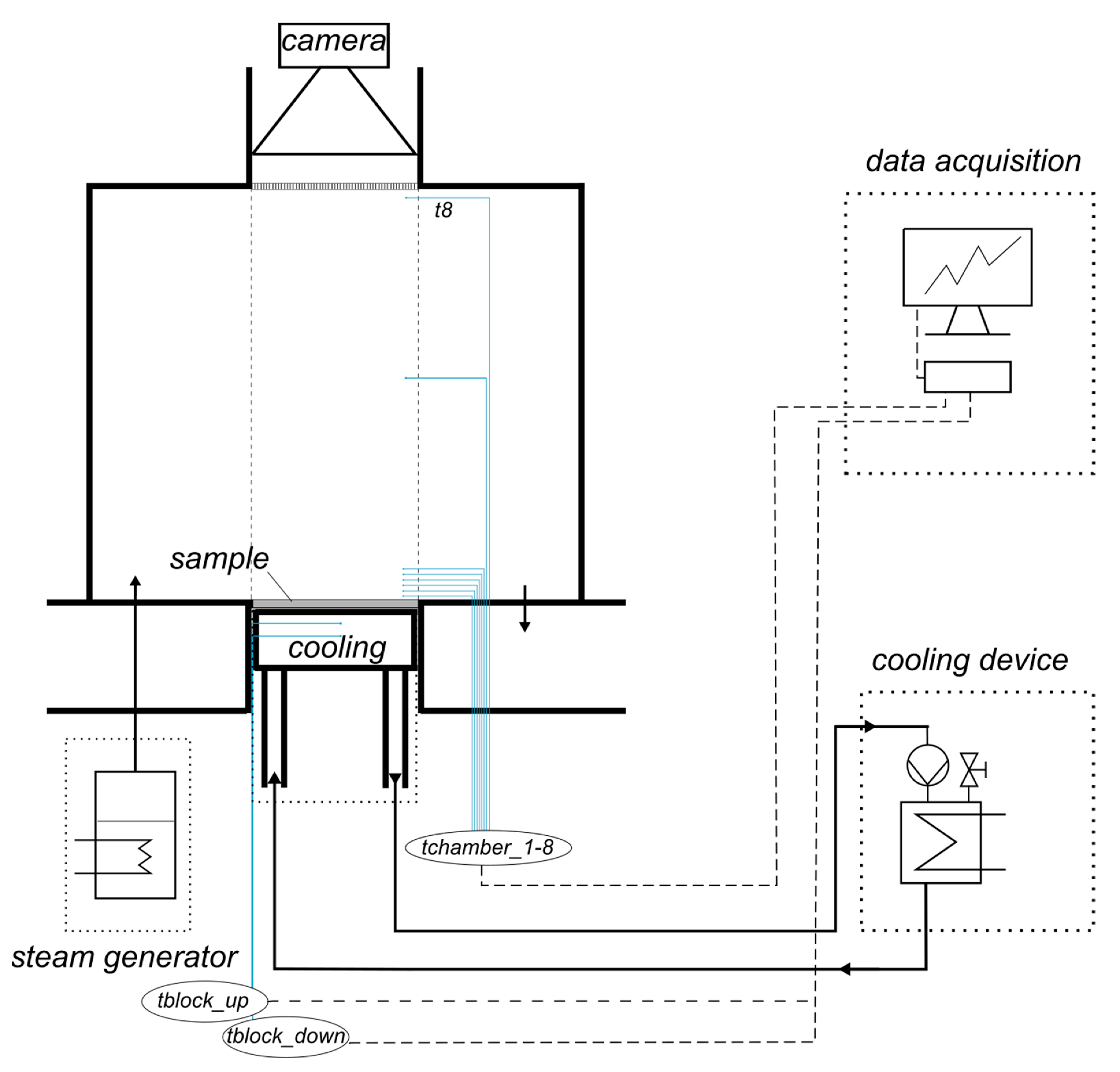
Steam condensation experiments at atmospheric pressure conditions on the described samples were performed in the setup, schematically presented in
Figure 1. The experimental procedure consisted of the following steps:
(a) Setup assembly: The sample under investigation was placed onto the cooling block covered with a thin layer of equally distributed thermal paste (Arctic MX-4) in order to provide the maximal thermal contact between the sample and the block. Afterwards, a cylindrical chamber of 3.4 L in volume (polycarbonate, 170 × 150 mm with wall thickness of 5 mm) was fastened with screws. An observation window was provided at the top of the chamber, to observe the condensation process. All condensation experiments were done by tilting the setup with a sample to an angle of 15° relative to horizontal. This allowed the continuous removal of the condensate droplets from the sample as they were flowing back to the steam generator vessel.
(b) Cooling: The sample was cooled from below by a flow of demineralized water passing through the cooling copper block. The inlet temperature of the cooling water was (5 ± 0.3) °C. Adjusting the rotameter to the flow rate of 0.4 kg/min, the difference in temperatures between the cooling water inlet and outlet was kept less than 5 °C during each experiment.
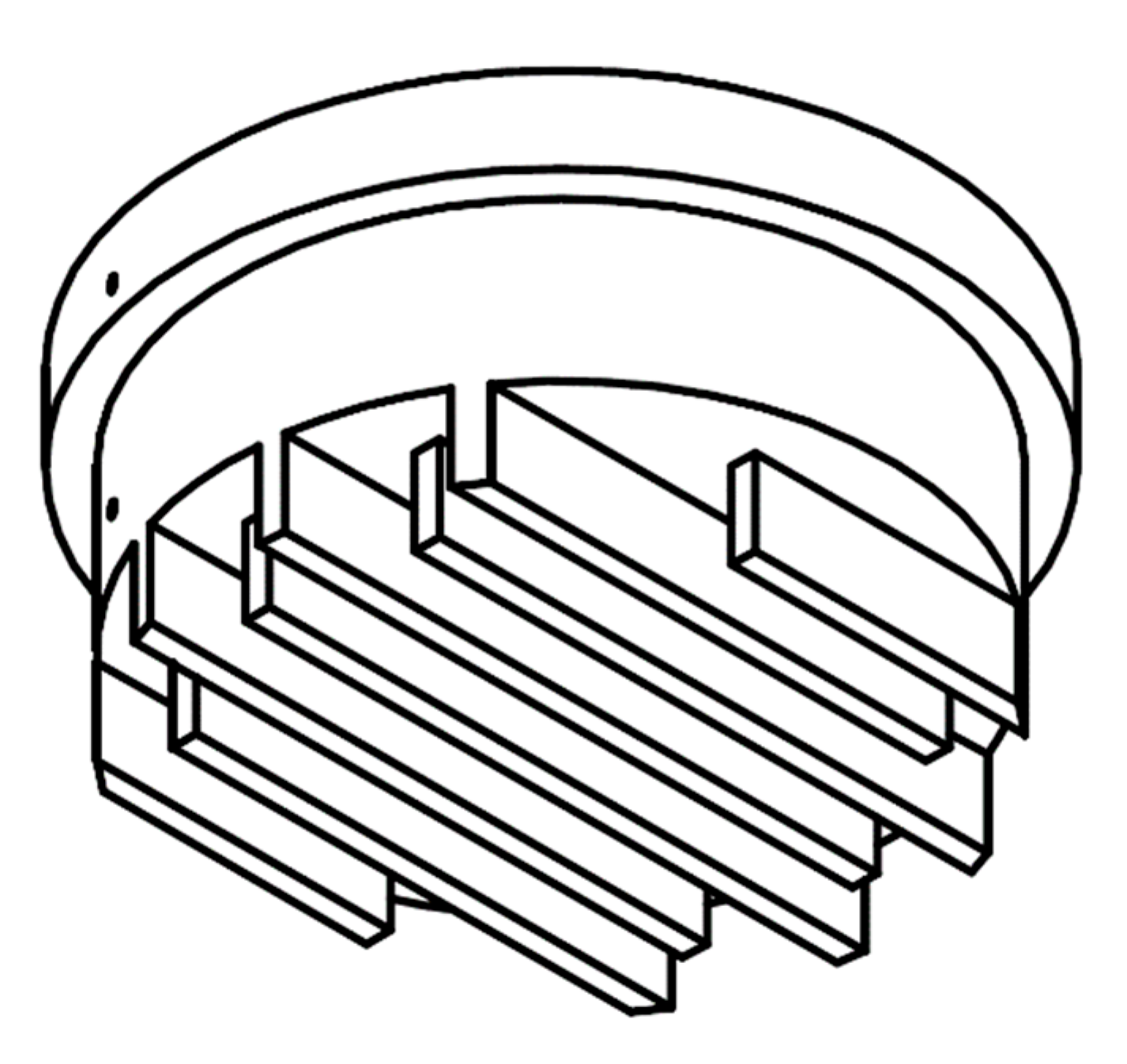
The cooling block of 60 mm in diameter was made out of copper (Cu > 99.9%, E-KUPFER) with labyrinth-like channels, as shown in
Figure 2. The 3D printed plastic counterpart (with Ø 3 mm openings for the cooling water inlet and outlet) closed the copper block from below to create the 4 × 4 mm channels for the cooling water circulation. Inside the block there were two parallel holes of 1 mm in diameter passing 30 mm deep to the center. Two thermocouples (T-type, Class 1, D = 1 mm) were covered with thermal paste and mounted into these holes at a distance of 10 mm between each other and at a distance of 5 mm from the condensing surface. These temperature measurements (
,
) were used to calculate the heat flux during each experiment, assuming one-dimensional conduction through the copper block [
13,
17].
(c) Steam generation: Connected to the condensation chamber via a hose (inner diameter of 16 mm), the steam generator (1 kW) was filled with demineralized water (500 mL). Its temperature was increased to a boiling point by the heater, which was connected to the transformer. Steam flow rate was determined in the preliminary tests from the amount of evaporated water in time as a function of voltage. Adjusting the voltage on the transformer allowed the evaporation of water at different rates (2, 4, and 6 mL/min) and the continuous production of steam (2, 4, and 6 g/min, respectively). In the case of the highest investigated steam flow rate (6 g/min), the steam velocity in the system was calculated to be below 1 m/s. Steam filled the whole chamber and left through the outlet opening of 16 mm in diameter.
(d) Measurement: The temperature profile along the chamber was measured by eight thermocouples (T-type, Class 1, D = 1 mm), which were positioned at the following distances to the sample: 1, 3, 5, 8, 10, 13, 80, and 145 mm, respectively. The measured data (, , ) was collected by the Data Acquisition System (DAQ), using the LabVIEW 2017 software.
The preparatory phase including the cooling and steam generation lasted up to one hour, while the condensation experiment itself was considered to have started as soon as the steady-state conditions inside the chamber were reached (all the chamber thermocouples showed the similar stable values). Shown in
Table 1, a series of consecutive condensation experiments, each lasting for one hour, was performed with the samples O1, O2, and N1. A series of longer-term condensation experiments (five hours each) was carried out wih the sample N2.
After each condensation experiment, the sample was dried with the weak flow of pressurized air at 1 bar at a distance of 50 cm. Afterwards, the sample’s wettability was characterized and digital microscope images of its surface were taken, as described in
Section 2.1.
The condensation heat flux
q (kW/m
2) was calculated assuming one-dimensional heat conduction in the cooling block:
k is the thermal conductivity of the material (in this study 0.401 kW/(m⋅K) for copper at 0 °C),
z is the distance between the thermocouples in the cooling block (0.01 m), and (
) is the measured temperature difference between the upper and lower thermocouple in the cooling block.
The calculated heat flux was averaged over the experimental duration (over one hour or over five hours, depending on the experiment, as in
Table 1). The standard deviations from the average values are represented by vertical bars later in the resulting graph.
3. Results
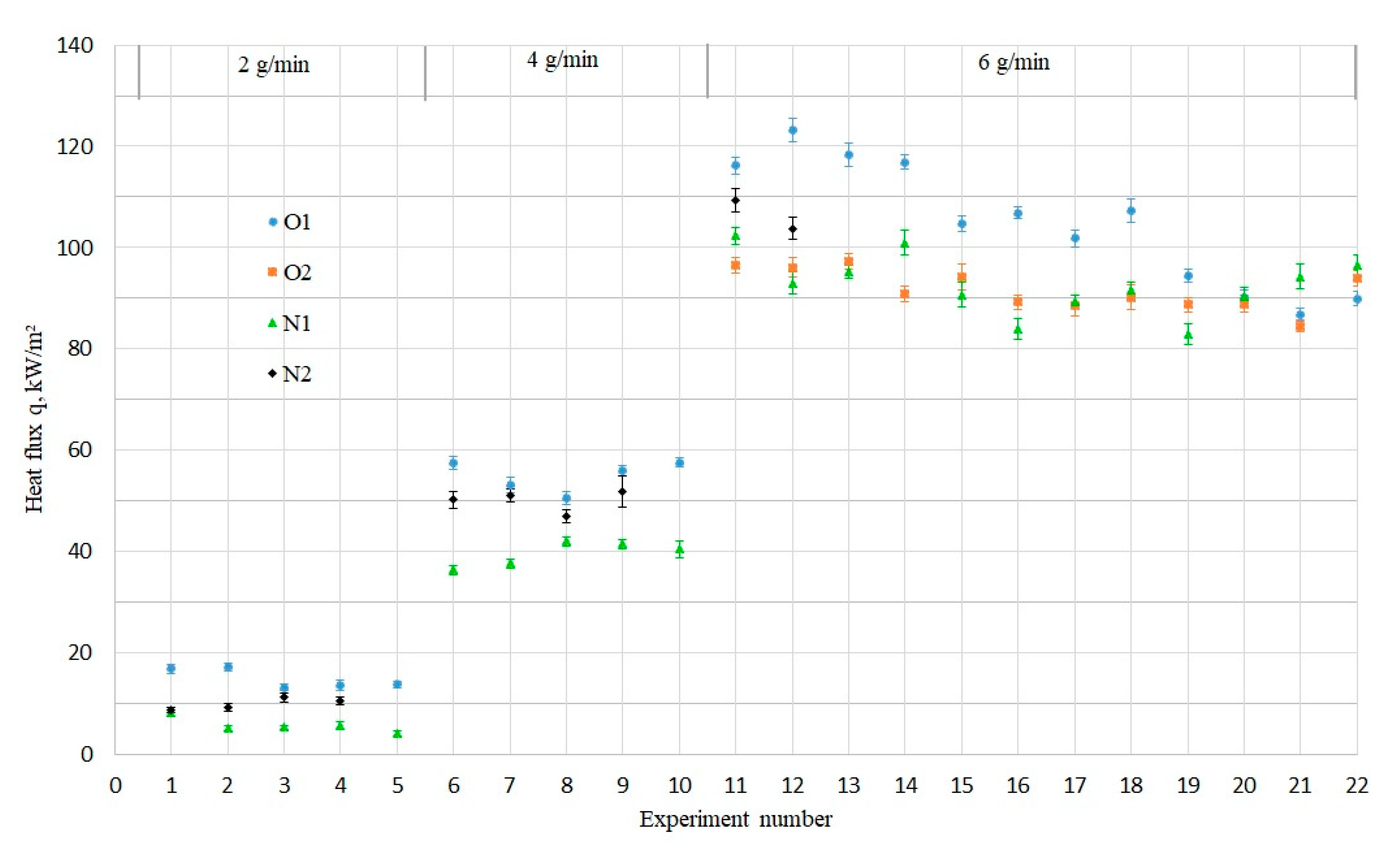
As presented in
Figure 3, the condensation experiments with the investigated samples (O1, N1, and N2) were carried out sequentially starting with the lower steam flow rate of 2 g/min, increasing it to 4 g/min, and then to 6 g/min. The sample O2 was exposed directly to the condensation conditions under the highest investigated steam flow rate (6 g/min).
The increase in the steam flow rate led to the increase in the condensation heat flux as expected. The heat flux values were scattered within the same region, independent of the sample: around 10 kW/m2 for 2 g/min, around 50 kW/m2 for 4 g/min, and around 100 kW/m2 for 6 g/min.
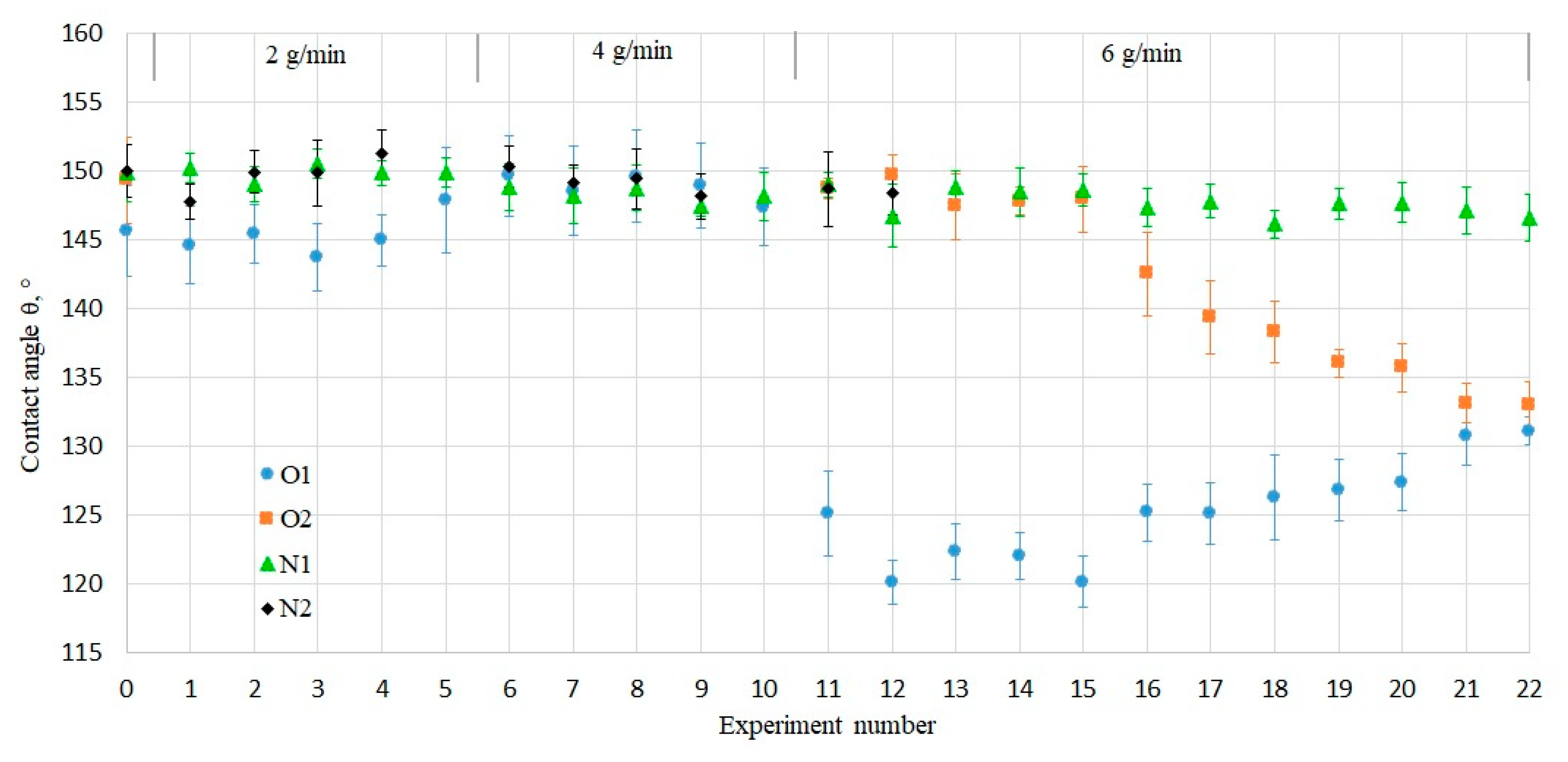
The obtained heat fluxes were observed in combination with the measured water contact angles after each condensation experiment. They helped to notice the influence of the experimental condensation conditions on the wettability of samples and to follow the loss of their superhydrophobic properties. As demonstrated in
Figure 4, the initial contact angles (Exp. № 0) on all samples were within the superhydrophobic range of 145–150°. The criteria for superhydrophobicity regarding the contact angle hysteresis to be less than 10° was also fulfilled, since the initially measured hysteresis on all samples was lower than 3°.
At low steam flow rates of 2 and 4 g/min, the heat flux through every sample (
Figure 3) stayed relatively constant and contact angle measurements (
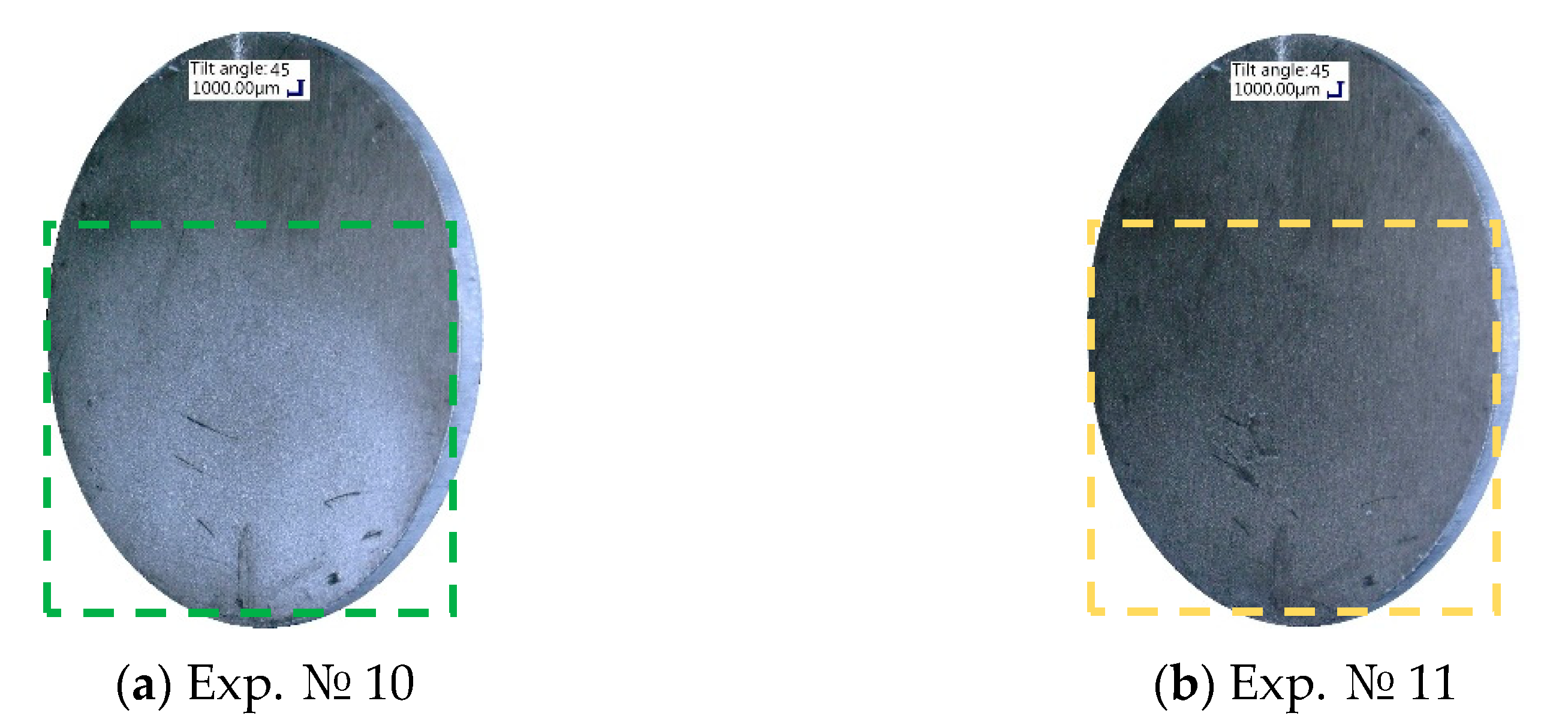
Figure 4) showed no significant changes. At the steam flow rate of 6 g/min, the heat flux through the samples decreased. The most rapid reduction of 20% over the experimental series was exhibited by the old-coated sample O1, which is connected with the pronounced decrease in the contact angle values, due to the partial coating washout. This coating deterioration could be visually observed, as shown in the digital microscope images in
Figure 5. After the fifth condensation experiment at the steam flow rate of 4 g/min (
Figure 5a), a milky white coating substance was noticeable on the O1 sample. On the contrary, immediately after the first condensation experiment at 6 g/min steam flow rate (
Figure 5b), no more coating whiteness was visible and the coated sample looked grey.
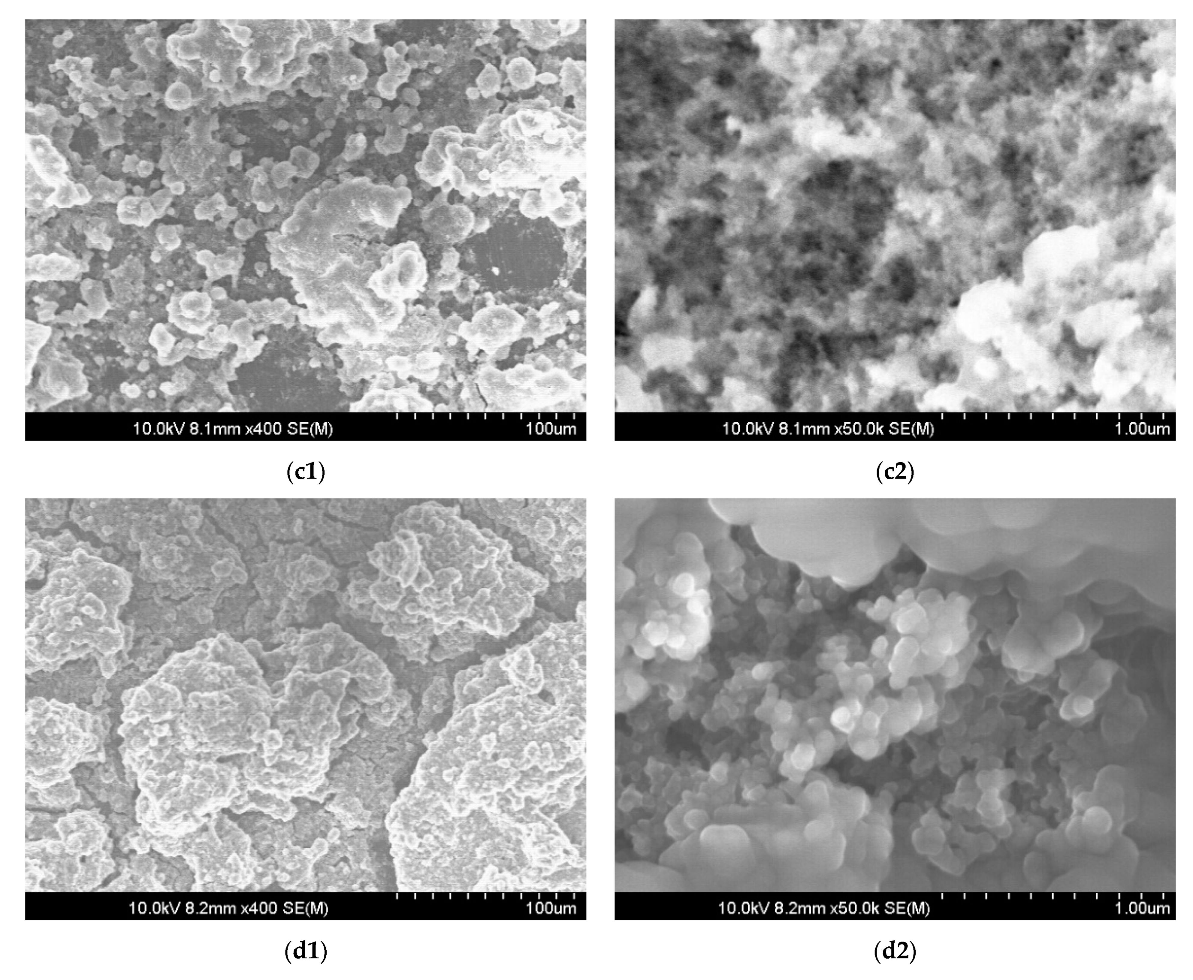
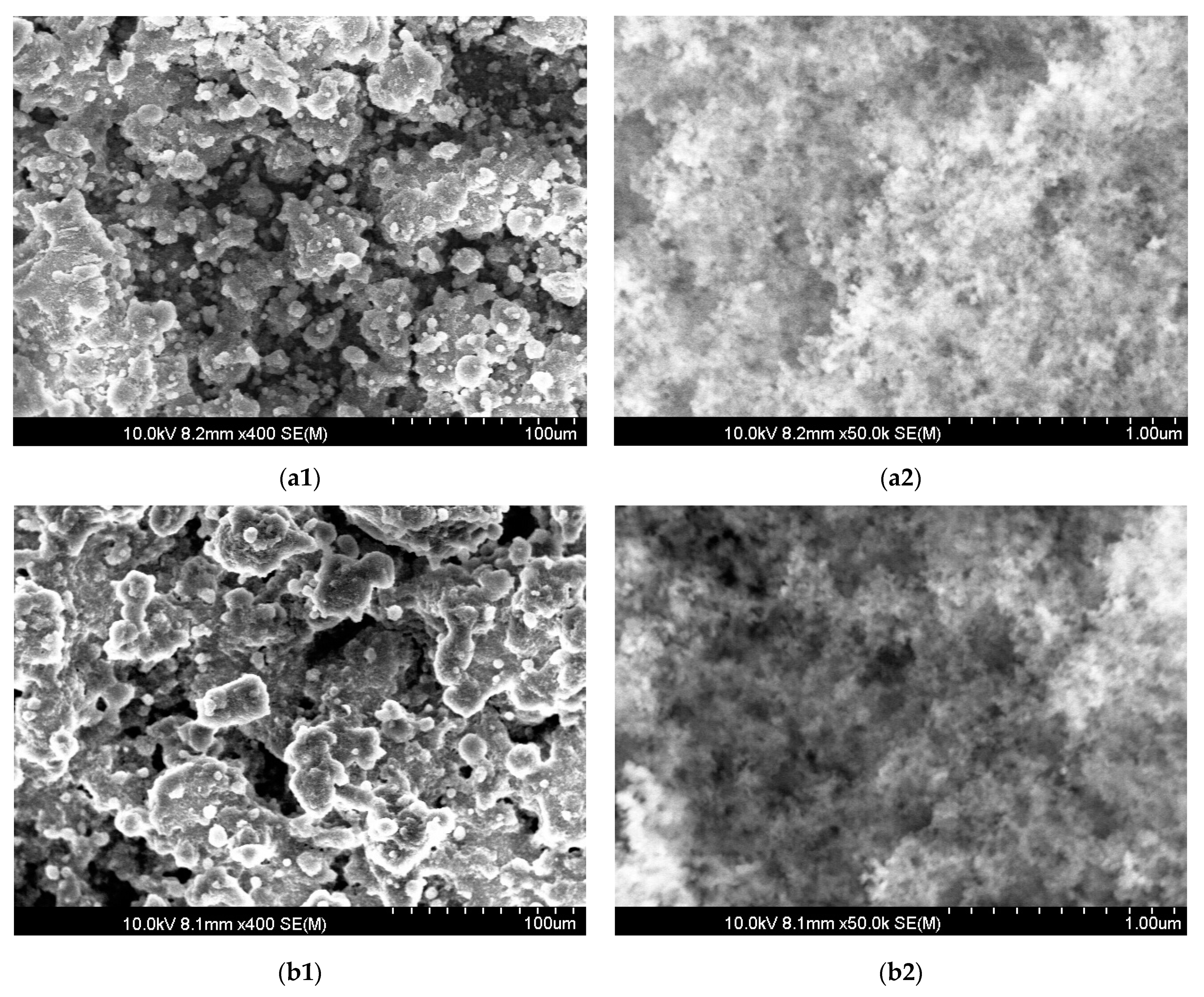
The mechanical degradation of the used coating was confirmed by observing modifications in the surface morphology. SEM images were taken at the end of all condensation experiments for the new-coated sample N1 and the old-coated sample O1, presented in
Figure 6. The images of the new-coated and old-coated samples before the condensation experiments are presented as reference samples and show that the initial condition of surfaces (
Figure 6(a1,a2,b1,b2)) was similar. After exposure to more than twenty consecutive hours of steam condensation, the N1 sample (
Figure 6(c1,c2)) had a morphology similar to the freshly coated substrate before exposure to condensation (
Figure 6(a1,a2)). On the one hand, noticeable at low magnification, the sample N1 had significantly less particles with diameters below 10 μm, whose absence is especially visible on the surfaces of bigger particles (compare
Figure 6(a1,c1)). On the other hand, the sample N1 had more particles with sizes less than 20 μm (
Figure 6(c1)) in comparison to the morphology of the old-coated sample O1 (
Figure 6(d1)). The absence of small particles indicated the partial washout of the coating during condensation. This probably influenced the refractive index of the coating, making the sample O1 look grey, as presented in
Figure 5b. Although the structures were hierarchical on both samples, microparticles of the N1 sample were porous and sharp, resembling a sponge-like structure (
Figure 6(c2)) similar to the new-coated sample before exposure to condensation (
Figure 6(a2)), whereas the micro-particles of the O1 sample had hilly round surfaces (
Figure 6(d2)). These changes detected with the help of the SEM indicated the deterioration of the coating polymer under the influence of condensation conditions.
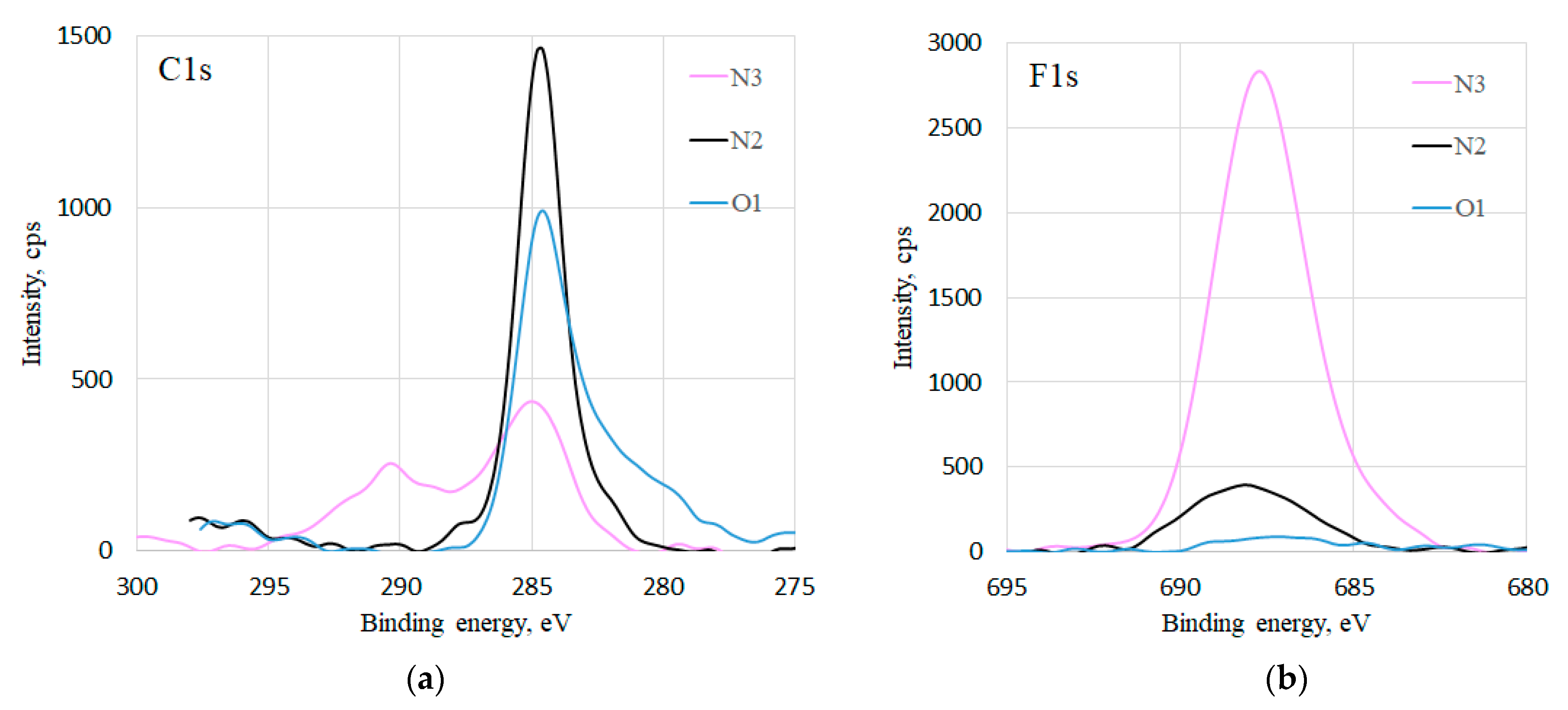
Deterioration of the coating was also revealed by the XPS composition characterization of the samples O1, N2 at the end of all condensation experiments, and of a referent freshly coated sample N3, which was not subjected to condensation experiments (
Figure 7). High resolution C1s spectra of all the samples (
Figure 7a) show at 285 eV the C-C and C-H signals that stem from the adventitious C. The signals at 287.8 eV, 290.8 eV, and 292.7 eV correspond to CF, CF
2, and CF
3 bonds [
18], respectively, which are only present in the N3 sample’s spectra. In the F1s spectra (
Figure 7b), it can be seen that the sample N3 has the highest fluorine signal, while for the samples N2 and O1, the intensity is much lower. This confirms the findings from the SEM images, i.e., that there is a loss of fluorinated particles on the surface, which takes place even in case of the sample N2.
The drop in contact angle from 147° (superhydrophobic) to 125° (hydrophobic) on the sample O1 took place after the first hour at the highest investigated steam flow rate of 6 g/min (
Figure 4, Exp. № 11). In order to investigate the origin of the drop in contact angle, the experiments were repeated on the similar old-coated sample O2. In this case, more than ten consecutive hours of condensation experiments at 6 g/min were required to observe the decrease in the contact angle to the same hydrophobic value of about 130° as for thesample O1. This signified that not only the increased steam flow rate, but also the exposure time to condensation plays a crucial role on the wettability of coated surfaces and their heat flux.
The reduction of heat flux with time occurs not only in cases of spray-coated surfaces. As reported by Torresin et al. [
13], the nanotextured copper surface with a self-assembled monolayer showed a 35% decrease in heat flux after five consecutive days of condensation at 110 °C and 12 m/s vapour velocity. The change in condensation mode from dropwise to filmwise happened on the sixth day. The authors attributed it to the gradual mechanical degradation of the surface, due to the sustained exposure to high temperatures and vapour velocities. This corresponds to the study of Jo et al. [
19], who examined the loss of superhydrophobicity of micro/nano structures on zirconium alloy plates during condensation. The researchers reported that apart from the surface morphology, the condensation conditions influence the condensation mode [
19,
20]. They found out that the SHPhob surfaces lose their novel characteristics at high supersaturated water vapour conditions.
The present study shows that the storage period of the coated samples is an important parameter to consider prior to condensation, since the one-year-old coated samples O1 and O2 lost superhydrophobicity with time and became hydrophobic after exposure to condensation conditions at different steam flow rates (
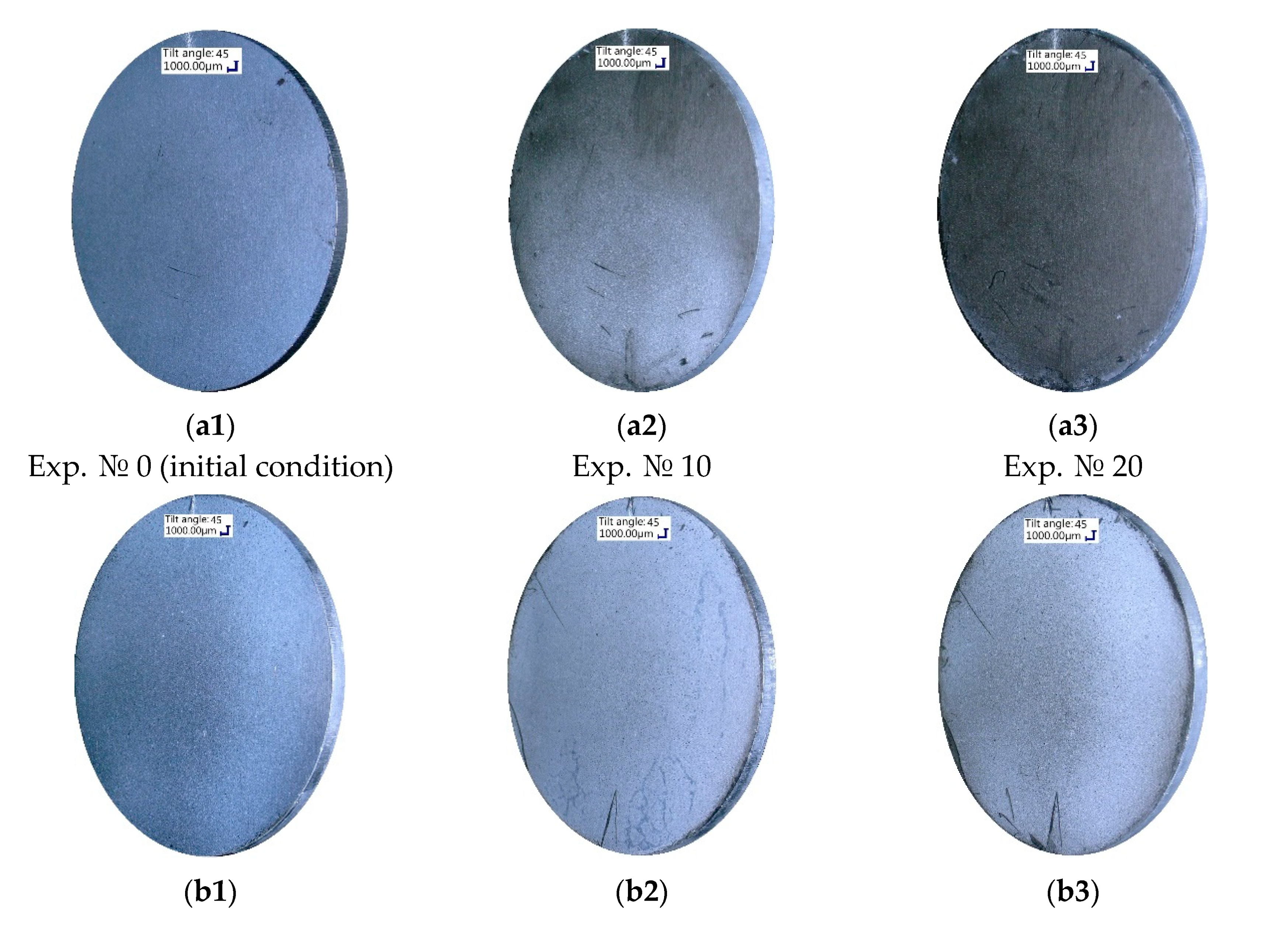
Figure 4). Remarkable for the new-coated samples N1 and N2 was their preservation of superhydrophobic surface properties after exposure to more than twenty and fifty hours of condensation, respectively. Apart from the measured contact angles and heat fluxes, this could also be seen visually in
Figure 8, which presents the partial coating degradation by the end of the experimental series on the example of the old-coated sample O1 (
Figure 8a) and the coating preservation on the example of the new-coated sample N1 (
Figure 8b). This may be related to the changes that have occurred on the coating surface during storage. In this study changes in the morphology could be verified by SEM imaging (
Figure 6). Additionally, some modification of the surface chemistry upon aging in air is possible.
The difference in the droplets’ behaviour could be noticed from the video recordings during the contact angle measurements on the coated samples. In the initial state before condensation experiments (
Video S1), the droplets did not stick to all the coated samples, since their surfaces were superhydrophobic and adhesion between the droplet and surface was low. It was impossible to freely place a droplet on the sample; therefore, the contact angle measurements were performed with a needle inside of the droplet, as described in
Section 2.1. In the final state after all condensation hours, the droplets stuck to the samples, as demonstrated in
Video S2. This was attributed to another phenomenon, namely, the adsorption of condensed water within the porous structures of the coating during condensation.
Three months after the described condensation experiments, the contact angles on the old-coated samples were remeasured. Remarkably, the droplets again did not stick to the samples’ surfaces and contact angle values returned to the superhydrophobic range (145–150°). This phenomenon corresponds to the findings of Yin et al. [
21], who showed that the loss of superhydrophobicity during condensation could be recovered completely after a drying process at room temperature. Boinovich et al. [
22] studied the mechanisms of water contact angle deterioration in time (reversible and nonreversible) on hydrophobic and superhydrophobic surfaces with long-term continuous contact with water. The researchers pointed out that the growth of adsorption/wetting films and the reversible hydration of active sites, tending to create hydrogen bonds, cause the reversible deterioration of hydrophobicity, which could be restored by drying.
In summary, the SHPhob-coated samples that were stored for one year prior to the condensation experiments became hydrophobic under the influence of time and at elevated steam flow rates (6 g/min). The joint effects of the partial coating washout and adsorption of the condensed water within the porous structures of the coating during steam condensation were shown to be responsible for that change. On the contrary, the samples coated a few days before the experiments were able to sustain more than fifty hours of steam condensation while keeping the same heat flux and SHPhob wettability values. Future research will aim to investigate the mechanical degradation of the coating upon steam condensation, as well as the chemical composition of the condensate and of the residual coating on the samples.


 ,
, 


