Article

Optimal Design of Accumulator Parameters for an Electro-Hydrostatic Actuator at Low Speed

1
School of Mechanical Engineering, Yanshan University, Qinhuangdao 066004, China
2
Mechanical and Electrical Engineering, Xinjiang Institute of Engineering, Urumqi 830023, China
*
Author to whom correspondence should be addressed.
Processes 2021, 9(11), 1903; https://doi.org/10.3390/pr9111903
Submission received: 31 August 2021 / Revised: 19 October 2021 / Accepted: 20 October 2021 / Published: 26 October 2021
(This article belongs to the Topic Modern Technologies and Manufacturing Systems)

Abstract

:
The electro-hydrostatic actuator (EHA) is a type of highly integrated, compact, closed pump control drive system composed of a servo motor, a metering pump, a hydraulic cylinder and other components. Compared with the traditional valve control system, the electro-hydrostatic actuator has the advantages of a high power-to-weight ratio, high integration, environmental friendliness, and superior efficiency and energy saving. However, due to the complex mechanical–hydraulic coupling mechanism of the system and the existence of non-linear multi-source disturbances, the dynamic and static performance of the system is limited, particularly the pressure pulsation phenomenon under low-speed conditions, which seriously affects the high precision control requirements of the system. In order to address the low-speed pressure pulsation problem of the electro-hydrostatic actuator, first, the mathematical models of the servo motor, metering pump and hydraulic cylinder are established, and the simulation model of the EHA system is created based on MATLAB/Simulink. Second, from aspects of the servo motor and the quantitative piston pump, the causes of the pressure pulsation under low-speed working conditions are analyzed, and the parameter selection method of the accumulator is proposed to eliminate the pressure pulsation based on ω n and ζ of the EHA system. Finally, the optimal charging pressure of the accumulator is simulated and experimentally analyzed. The simulation and experimental results show that the charging pressure range of the accumulator calculated with this method can effectively improve the pressure pulsation phenomenon of the EHA system under low-speed working conditions, and it plays a positive role in the engineering popularization and application of the EHA system.

1. Introduction

The electro-hydrostatic actuator (EHA) is a type of high-performance servo drive device originating from the field of aviation. It has the advantages of a high power-to-weight ratio, low operation and maintenance costs, environmental friendliness, and superior efficiency and energy saving [1]. It has been successfully applied in automobile active suspension [2], tank guns [3], robots [4], ships [5] and in other fields. However, the EHA system uses the concept of a servo motor driving a metering pump for volume speed regulation. The coupling mechanisms between the mechanical, electronic and fluid components in the EHA system are complex; at the same time, due to the time-varying parameters of the external load, the internal leakage of the system, the oil compressibility and other non-linear factors, the dynamic and static performance of the system is limited, particularly with regard to the pressure pulsation problem under low-speed operating conditions. This issue seriously restricts the popularization and application of the system. With a view to investigating the pressure pulsation phenomenon inside the system under low-speed output conditions, researchers started with the causes of the pressure pulsation, and carried out relevant studies on the servo motor and the metering pump in the system as follows.
Under low-speed operation, the output speed of the servo motor fluctuates due to cogging torque, magnetic flux harmonic and other factors, resulting in the pulsation of the system output flow and pressure. To solve this problem, Liu et al. used a two-channel rotary transformer to measure the position of the universal joint, and deduced a feedback calibration method to solve the speed fluctuation problem of the servo motor under low-speed conditions, which improved the torque precision of the control momentum gyro [6]. Makino et al. confirmed that the torque pulsation strongly depends on the parameters used in models of magnetizing curves and the torque-rotor position-current characteristic, and then presented two approaches to achieve precise torque control under the instantaneous current profiling technique in switched reluctance motors [7]. Combining adaptive PID-type sliding mode control (APIDSMC), model reference adaptive control (MRAC) and periodic adaptive learning control (PALC), Zhang et al. introduced an adaptive PID-PALC compensation method in relation to energy efficiency, which suppressed the influence of the torque ripple in the permanent-magnet synchronous motor (PMSM) servo system, ensured good position control precision of the system and improved the energy utilization efficiency [8]. Liu et al. analyzed the EM torque ripple of PMSM with a similar number of poles and slots, investigated the rotor step skewing method and harmonic current compensation method to reduce the EM torque ripple, and validated the effectiveness of the two optimization methods using the finite element method (FEM) and prototype experiments [9]. Based on the permanent-magnet synchronous motor model, Bu et al. analyzed the reasons for torque ripple and influence and proposed a virtual torque control method for a direct drive permanent-magnet synchronous motor servo system at low speed. The analysis and experimental results showed that the proposed control method was effective for a smooth speed during low-speed running [10]. Nos et al. proposed a control method to improve the position tracking accuracy of a low-speed servo system that uses multiple resonant terms in parallel and a traditional velocity proportional integral (PI) controller. The experimental results showed the viability and effectiveness of high-performance tracking operations through the elimination of the selected speed pulsations [11]. Bu et al. proposed a rotor position tracking control (RPTC) strategy for the speed fluctuations of a direct-drive PMSM servo system operating at low speed under different torque perturbations that has a good speed performance for both periodic and aperiodic torque perturbations [12]. In order to suppress the harmonic component in the stator current and reduce the torque ripple of the permanent-magnet synchronous motor, Huang et al. proposed a fractional-order based resonant controller (FOBR), which has a better harmonic suppression effect than the integer-order quasi-resonant controller and the pure proportional integral controller [13]. Asama et al. proposed a novel double-layer annular winding slotless permanent-magnet motor to reduce the torque ripple of the servo motor, and applied it to the servo motor system with precise positioning control. The proposed double-layer annular winding layout reduced the torque ripple by 0.12%, and improved the dynamic and static performance of the system [14]. Lin and Ting analyzed highly nonlinear factors, such as cog torque, stator current time harmonic and flux saturation of a synchronous reluctance motor, and then proposed a novel non-linear backstepping control system using the upper bound with a switching function for controlling the synchronous reluctance motor drive system to compensate for the lumped uncertainty [15].
The above scholars mainly developed high-performance control strategies and optimized the structure of the servo motor to suppress its torque fluctuation. In practical engineering applications, the introduction of a high-performance control algorithm often increases the cost and cycle of research and development, resulting in a huge program volume and a high failure rate. Optimizing the body structure of a servo motor can weaken the influence of torque ripple to a certain extent, but there are often no mature reliable products to choose from in practical engineering.
Addressing the pressure pulsation phenomenon existing in the ration pump, Pan et al. analyzed the influence of swash plate vibration on the flow pulsation and pressure pulsation at the outlet of the axial piston pump, and established a theoretical model of the flow pulsation at the outlet of the pump. Based on the theoretical model, the valve plate was optimized [16]. Wang and Wang modeled and simulated the axial piston pump based on AMESim software, and studied the flow pulsation characteristics under different factors. Theoretical analysis showed that the loading pressure, angular velocity, piston number and accumulator had obvious effects on the flow pulsation characteristics [17]. In order to solve the problem of flow and pressure pulsation in a large-capacity high-pressure piston pump, Liu et al. proposed an effective method to connect multiple accumulators charging different pressures with the outlet chamber of the pump, and the parameters of the accumulators were optimized [18]. By integrating the accumulator into the pump and optimizing the accumulator’s precharge pressure, Zhang et al. successfully reduced the pressure pulsation rate of the crankshaft seawater plunger pump from 17% to less than 5% [19]. A dynamic analysis of the swash plate vibration and pressure pulsation of an aircraft piston pump was carried out by Ouyang et al. based on the fluid–structure coupling theory. The results of the research showed that the full fluid–structure interaction (FSI) model was much more accurate in predicting the vibration of the swash plate and the pulsation of the discharge pressure than the non-FSI model [20]. Xu et al. studied the influence of speed, swash plate angle and working pressure on the flow pulsation of a pump, and tested the output flow pulsation of the pump. Compared with the pressure change, the test accuracy of flow pulsation was more sensitive to a change in speed [21]. Zhang made use of computational fluid dynamics technology to carry out a visual simulation of the flow pulsation process of a water pressure axial piston pump. With and without considering cavitation, the flow pulsation rate and other parameters of the flow field under different speeds and different loads were obtained, respectively [22]. Zhang et al. established a flow mathematical equation of a double-row axial piston pump, studied the flow pulsation of the piston pump with different structural parameters, such as the number and distribution of the plunger, and obtained the change laws of the flow pulsation of the double-row axial piston pump [23]. Zhang demonstrated a pressure pulsation function model, simulated the function curve of pressure pulsation and solved the excitation problem necessary for the vibration and noise analysis of hydraulic pump systems [24].
The above scholars considered the influence law of the swash plate angle and vibration of the plunger pump, the number and distribution of the plunger, the loading pressure, the cavitation of the working medium and other factors on the system pressure pulsation and flow pulsation, improving the pressure pulsation phenomenon to some extent by optimizing the structural design of the plunger pump.
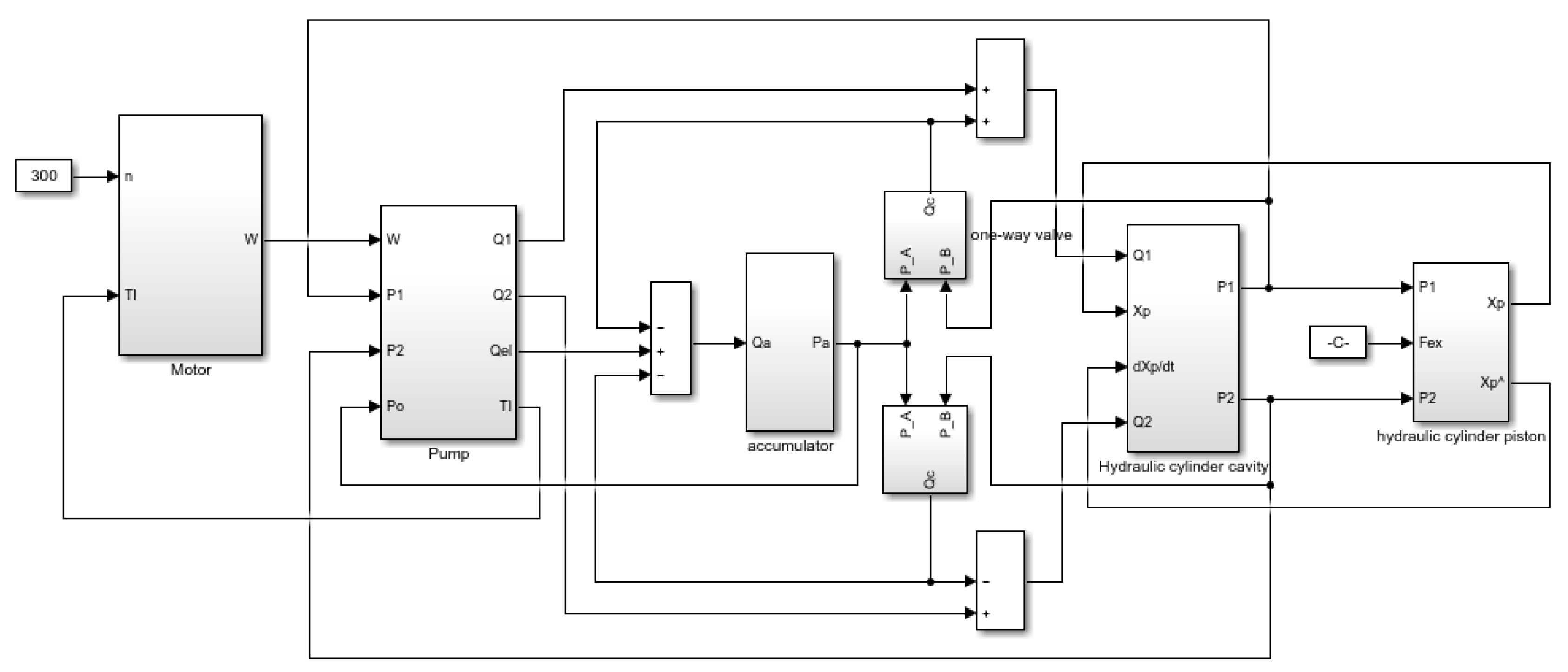
In this paper, we take the EHA system as the research object, focus on the pressure pulsation phenomenon existing in the system, and improve the low-fast dynamic and static characteristics of the EHA by optimizing the accumulator volume and charging pressure parameters.

2. Overview of Electro-Hydrostatic Actuator (EHA) System

In the EHA system, the servo motor drives the quantitative pump, and the liquid medium drives the double-acting hydraulic cylinder to move in two directions through the hydraulic pipeline. The system adopts volume speed regulation control technology, which has the advantages of a flexible installation mode, no overflow or throttling loss and high efficiency. In this paper, the EHA system is mainly composed of a servo motor, a metering displacement bi-directional hydraulic pump, an accumulator, a one-way valve, a relief valve, a double-acting hydraulic cylinder and other components. The specific structure principle is shown in Figure 1.
In Figure 1, the operating state of the system is monitored by temperature and pressure sensors. When the amount of oil in the system is reduced due to system leakage and other factors, the oil in the fill oil accumulator is supplemented by the one-way valve to the oil in the system. The relief valve is used as a safety valve to limit the maximum pressure of the system. After the system stops working, the unloading valve opens, the pressure between the high- and low-pressure chambers balances each other and the system is unloaded.

3. EHA System Modeling and Simulation

3.1. Mathematical Modeling and Simulation Analysis of Servo Motor

Without changing the basic functions of the servo motor, the mathematical model of the servo motor is established by ignoring some complex non-linear factors that have little impact on the system inside the servo motor.
The stator flux equation of the servo motor is as follows:
{ ψ d = L d i d + ψ f ψ q = L q i q
The stator voltage equation of the servo motor is as follows:
{ U d = R s i d + d d t ψ d ω e ψ q U q = R s i q + d d t ψ q + ω e ψ d
The electromagnetic torque equation of the servo motor is as follows:
T e = 3 2 p n [ ψ f i q + ( L d L q ) i d i q ]
The motion equation of the servo motor is as follows:
T e T L = J L d ω m d t + D ω m
where ψ d   and   ψ q are the d-q axis components of the stator flux linkage; L d   and   L q are the d-q axis equivalent inductance of the stator inductance; i d   and   i q are the d-q axis components of the stator current; ψ f is the permanent flux; U d and U q are the d-q axis components of the stator voltage; R s is the stator resistance; ω e is the angular velocity of the rotor; T e is the internal electromagnetic torque; p n is the number of pole pairs of the permanent-magnet synchronous motor; T L is the load torque; J L is the equivalent mass moment of inertia; ω m is the angular velocity of the servo motor; and D is the damping coefficient of the servo motor.
When the control mode of the servo motor is i d = 0 , the q-axis component of the stator current is used to generate the electromagnetic torque. The electromagnetic torque is as follows:
T e = K t i q
where K t is the sensitivity coefficient of torque, which is related to the fixed parameters P n and ψ f of the motor.
According to Equation (2), the circuit voltage equation can be obtained as follows:
U q = L q d i q d t + R s i q + K e P n ω m
where K e is the back electromotive force coefficient.
If the Laplace transform is applied to Equations (4)–(6), the result is as follows:
{ T e ( s ) = K t I q ( s ) ω m ( s ) = 1 J L s + D [ T e ( s ) T L ( s ) ] I q ( s ) = U q ( s ) K e P n ω m ( s ) L q s + R s
The control block diagram of the servo motor speed control system based on the above Laplace transform is as follows:
From Figure 2, it can be concluded that the open-loop transfer function of the servo motor speed regulation system is as follows:
G ( s ) H ( s ) = K p K I K t K m L q J L s 2 + ( L q D + R s J L ) s + R s D + K e K t n p + K p K I K t K ω K m
The simulation model of the permanent-magnet synchronous motor built in the MATLAB/Simulink environment is shown in Figure 3.
The vector control of an AC permanent-magnet synchronous motor has three main parts: a speed loop regulator, a current loop regulator, and an Space Vector Pulse Width Modulation (SVPWM) control algorithm. The parameter settings of the speed loop and current loop in the simulation model are shown in Table 1 and the simulation model of the SVPWM control algorithm is shown in Figure 4.

3.2. Mathematical Modeling and Simulation Analysis of Pump and Hydraulic Cylinder

Considering the leakage, friction and other factors of the metering displacement bi-directional hydraulic pump, the mathematical model of the metering displacement two-way hydraulic pump is established as follows:
Q p = D p ω p C i p ( p 1 p r ) C e p p 1
where ω p is the rotate speed of the hydraulic pump; D p is the certified capacity of the hydraulic pump; Q p is the output flow of the hydraulic pump; C i p is the internal leakage coefficient of the hydraulic pump; C e p is the external leakage coefficient of the hydraulic pump; p 1 is the working pressure of the system; and p r is the fill oil pressure of the system.
The system adopts a self-priming oil supplementing scheme, and the oil supplementing pressure is far less than the system working pressure. After ignoring the oil supplementing pressure, the above equation can be simplified as follows:
Q p = D p ω p C p p 1
where C p = C i p + C e p and C p is the total leakage coefficient of hydraulic pump.
The flow continuity equation of the hydraulic cylinder is established as follows:
Q L = A p d x p d t + C t c p L + V t 4 β e d p L d t
where v t is the total compression volume; β e is the effective bulk modulus; A p is the effective area of the hydraulic cylinder; and C t c is the total leakage coefficient of the hydraulic cylinder.
The balance equation between the hydraulic cylinder and the load force is established as follows:
A p p L = m t d 2 x p d t 2 + B p d x p d t + K x p + F L
where m t is the total mass of the hydraulic cylinder piston and load converted to piston; B p is the total viscous damping coefficient; K is the spring stiffness of the load; and   F L is the external load force on the piston.
If the Laplace transform is applied to Equations (10)–(12), the result is as follows:
{ Q p = D p ω p C p P 1 Q L = A p s X p + C t c P L + V t 4 β e s P L A p P L = m t s 2 X p + B p s X p + K X p + F L
According to Equation (13), the control block diagram of the EHA hydraulic system is established as follows in Figure 5.
According to the control block diagram, the open-loop transfer function of the EHA hydraulic system is established as follows:
X p = D p ω p A P 1 A p 2 ( C t c + C p + V t 4 β e s ) F L m t V t 4 β e A p 2 s 3 + ( m t ( C t c + C p ) A p 2 + B p V t 4 β e A p 2 ) s 2 + ( 1 + B p V t A p 2 + K V t 4 β e A p 2 ) s + ( C t c + C p ) K A p 2
Ignoring the viscous damping and the elasticity of the load on the hydraulic cylinder (i.e., B p = 0 , K = 0 ), Equation (14) can be simplified as follows:
X p = D p ω p A P 1 A p 2 ( C t c + C p + V t 4 β e s ) F L m t V t 4 β e A p 2 s 3 + m t ( C t c + C p ) A p 2 s 2 + s

3.3. EHA System Overall Mathematical Model and Simulation

By integrating the above mathematical models, the transfer function block diagram of the EHA system is obtained as follows in Figure 6.
According to the hydraulic schematic diagram of the EHA system, the simulation model of the AC permanent-magnet synchronous motor and the simulation model of each hydraulic component in the hydraulic system are connected to form the overall simulation model of the EHA system as follows in Figure 7.
In the Simulink simulation process, to simulate the running status of the EHA system as accurately as possible, it is necessary to configure the parameters of the simulation components of the system, among which the hydraulic pump displacement, hydraulic cylinder working volume, piston effective area and other parameters can be calculated according to the performance indicators. Parameters such as the leakage coefficient and elastic modulus are obtained by measurement or experience. Table 2 describes the EHA system parameters.

4. Low-Speed Characteristics of the EHA System

In the EHA system, the servo motor and the hydraulic pump are connected by coupling. The servo motor output speed is uneven due to cogging torque, flux harmonic and other factors. At the same time, the limitation of the plunger pump’s own structure directly causes the output flow pulsation of the plunger pump. In the presence of the load, the output flow pulsation of the piston pump causes the pressure pulsation in the system.

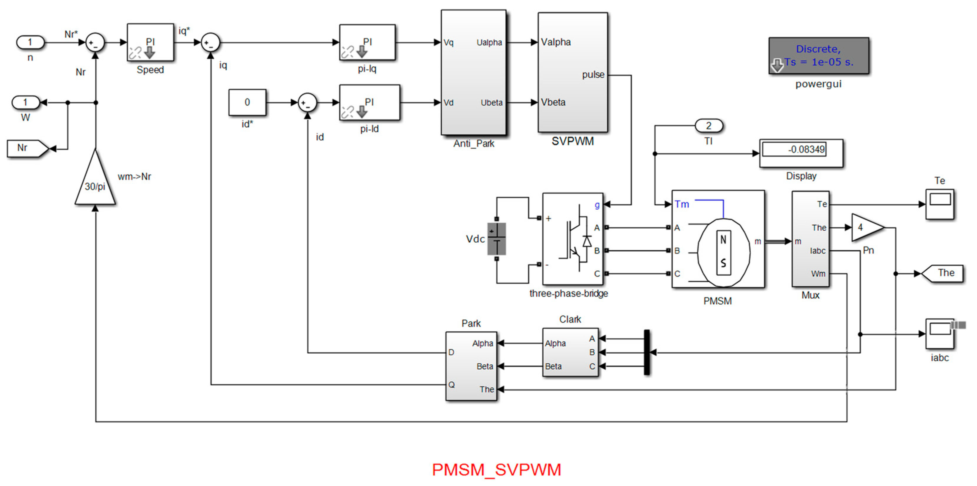
4.1. Analysis of Velocity Pulsation of Permanent-Magnet Synchronous Motor

The structure and control process of an AC permanent-magnet synchronous motor (PMSM) is the main source of PMSM speed pulsation, including cogent torque, flux harmonic, etc. The following is a theoretical analysis of these factors to obtain their influence on the velocity pulsation.
(1)
Cogging torque
The cogging torque is closely related to the mechanical structure of the servo motor and is generated by the harmonic magnetic field of the tooth caused by stator slotting. Cogging torque has periodic characteristics, and its changing period is related to the rotor position, the amount of cogging and the number of magnetic poles. The magnetic pole of the permanent magnet is divided into several blocks of the same width. Without considering the effect of saturation and end effect, the Fourier series of the cogging torque of a single permanent magnet is expressed as follows:
T c o g = n = 1 T n sin ( n N c o g θ e / p n )
where T c o g is the cogging torque; T n is the amplitude of the nth component of the cogging torque; and N c o g is the least common multiple of the number of cogs and the number of magnetic poles.
When the motor is running at high speed, the harmonic frequency of the coiling torque will increase and the amplitude will decrease. This is due to the filtering effect of mechanical harmonics, which weakens the effect of the higher harmonics. When the motor is running at low speed, the amplitude of the harmonics will increase sharply, and the stability of the motor is greatly reduced. Therefore, the cogging torque is a non-negligible influence on the smooth operation of the motor at low speed.
(2)
Harmonic flux
Due to the processing technology of a servo motor, the stator winding and permanent-magnet magnetic field cannot show an ideal sinusoidal spatial distribution, and due to the influence of the dead time effect, the stator current output by the inverter is mixed with many high-order harmonic currents, which are not sinusoidal. In the three-phase stationary coordinate system, the permanent-magnet flux linkage can be expressed as follows:
{ ψ a f ( θ e ) = ψ a f 1 cos θ e + ψ a f 5 cos 5 θ e + ψ a f 7 cos 7 θ e + ψ b f ( θ e ) = ψ b f 1 cos θ e + ψ b f 5 cos 5 ( θ e 2 π / 3 ) + ψ b f 7 cos 7 ( θ e 2 π / 3 ) + ψ c f ( θ e ) = ψ c f 1 cos θ e + ψ c f 5 cos 5 ( θ e + 2 π / 3 ) + ψ c f 7 cos 7 ( θ e + 2 π / 3 ) +
where ψ a f , ψ b f , ψ c f is the fundamental amplitude of the flux linkage in the three-phase coordinate system; ψ a f 5 , ψ b f 5 , ψ c f 5 is the fifth harmonic amplitude of flux in the three-phase static coordinate system; and ψ a f 7 , ψ b f 7 , ψ c f 7 is the seventh harmonic amplitude of flux in the three-phase static coordinate system.
By the Clark transformation and the Park transformation, the expression of the permanent-magnet flux in the d-q coordinate system is as follows:
{ ψ d f ( θ e ) = ψ d 0 + ψ d 6 cos 6 θ e + ψ d 12 cos 12 θ e + ψ q f ( θ e ) = ψ q 6 cos 6 θ e + ψ q 12 cos 12 θ e +
where ψ d f , ψ q f is the fundamental amplitude of the flux linkage in the d-q coordinates system; ψ d 0 is the DC component of the flux linkage in the d-axis; ψ d n is the nth harmonic amplitude in the d-axis; and ψ q n is the nth harmonic amplitude in the q-axis.
According to the electromagnetic torque equation and Equation (18), the following can be obtained:
T e = 3 2 p n ψ d f ( θ e ) i q = T 0 + T 6 cos 6 θ e + T 12 cos 12 θ e
where T 0 is the fundamental electromagnetic torque; and T 6 and T 12 are the sixth and seventh amplitude of the harmonic torque.
In summary, the cogging torque of AC PMSM varies periodically, and the disturbance period is related to the mechanical angular velocity, the number of cogging and the number of poles of the motor. Flux harmonics will introduce six-times higher harmonics, which cause current distortion and aggravate motor speed pulsation.

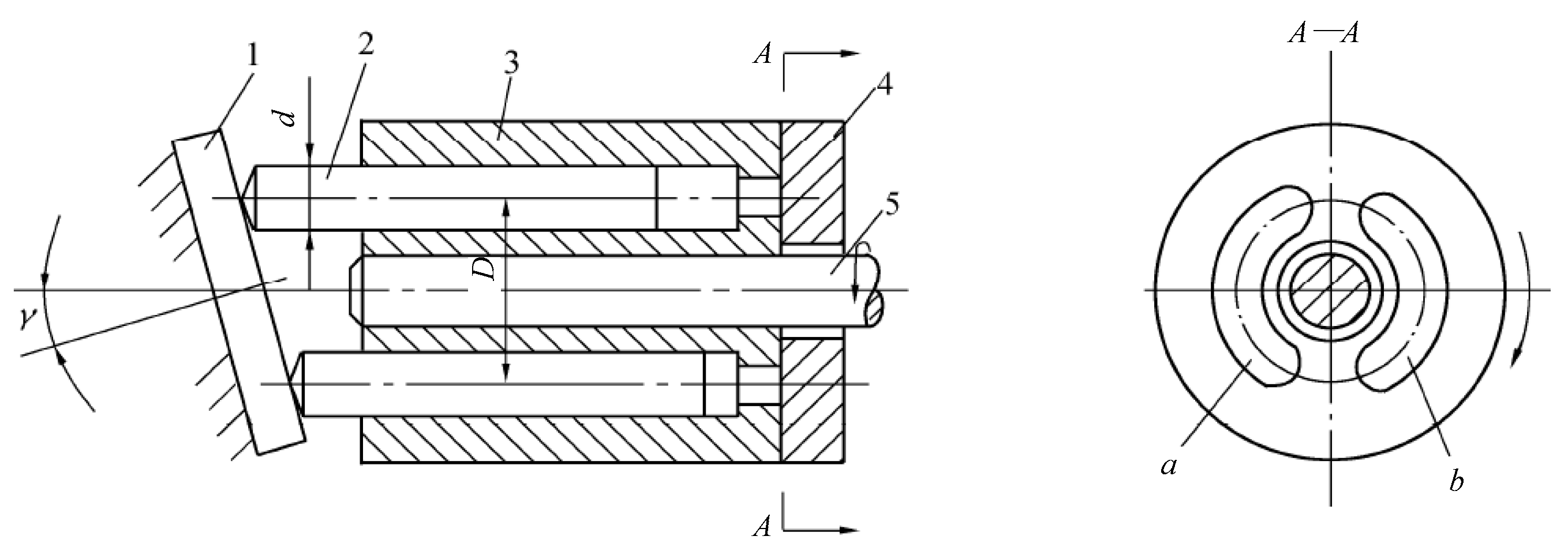
4.2. Analysis of Output Flow Pulsation of Swash Plate Axial Piston Pump

The motion of the single plunger in the swash plate axial piston pump can be considered as the synthesis of two motions: the reciprocating motion along the axis relative to the cylinder block and the rotary motion accompanying the cylinder block. The structure of the pump is shown in Figure 8.
When the number of plungers of the pump is odd, the instantaneous flow of the pump is as follows;
Q = π 4 d 2 D ω tan γ n = 0 m 1 sin ( φ + n 2 π z )
where d is the diameter of plunger; D is the diameter of the center distribution circle of the plunger; ω is the motor speed; γ is the angle of inclination of the swash plate; z is the plunger quantity; m is the number of plungers in the oil drain process; and φ is the angle of the drain plunger relative to top dead center.
If the Fourier series expansion of Equation (20) is carried out, the results are as follows:
{ Q = a 0 2 + n = 1 a n cos ( 2 n z φ ) a 0 = z 2 D d 2 ω tan γ a n = z D d 2 ω tan γ 2 ( 1 4 z 2 n 2 )
The flow of the piston pump can be divided into the constant part and the variable part. a 0 and a n are the amplitude of fundamental wave and low-order harmonic in flow pulsation, respectively.
In conclusion, it can be seen that the structure of the plunger pump itself leads to the reduction of the flow output quality of the system under low-speed working conditions. At the same time, due to the liquid resistance in the system pipeline, the flow pulsation will inevitably cause pressure pulsation. When the pressure pulsation frequency is close to the natural frequency of the pipeline system, it is easy to produce the resonance phenomenon and damage the components in the system.

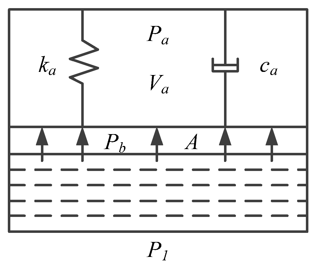
4.3. Study on Pressure Pulsation Absorbed by Accumulator at Low Speed

When there is flow pulsation in the hydraulic system, the accumulator can absorb the peak flow in the hydraulic pipeline and compensate the trough flow in the pipeline so as to reduce the flow pulsation and effectively reduce the pressure pulsation in the pipeline. The system adopts a bladder accumulator to absorb the pressure pulsation, which has the advantages of small running inertia and sensitive response.
According to the working principle of the accumulator, it can be simplified into the model shown in Figure 9.
The force equation of the air chamber is as follows:
( p b p a ) A = k a V a A + c a V a A
where P b is the oil pressure in the accumulator; P a is the gas pressure in the bladder; k a is the gas stiffness coefficient of the bladder at any time of operation; V a is the volume of gas in the bladder; c a is the coefficient of gas damping; μ is the coefficient of gas viscosity; and A is the cross-sectional area of the accumulator.
The volume change rate of the air chamber is opposite to the oil flow. Therefore, the above equation can be obtained by Laplace transformation:
[ p b ( s ) p a ( s ) ] A = ( k a A s + c a A ) Q ( s )
where Q ( s ) is the Laplace transform of oil flow.
Analysis of the oil in the accumulator and the establishment of the force equation of the oil chamber is as follows:
( p 1 p b ) A = m a d 2 V a d t 2 + B b d V a d t
where P 1 is the pressure at the accumulator inlet; m a is the mass of oil in the accumulator; and B b is the viscous damping coefficient of oil.
Combined with Equations (23) and (24), the force equation of the accumulator oil chamber can be obtained as follows:
( p 1 p a ) = m a d 2 V a d t 2 + ( B b + c a ) d V a d t + k a V a A
Applying the Laplace transform of the above equation and establishing the mathematical model of the accumulator with the oil inlet pressure as input and the gas chamber volume as output results in the following:
G 3 ( s ) = V ( s ) p a ( s ) = A a 2 k x ω n 2 s 2 + 2 ζ ω n s + ω n 2
where k x = k a + k p 1 A a 2 V a 0 , k x is the equivalent stiffness coefficient of the accumulator model; ω n = k x m a , ω n is the undamped natural frequency of the accumulator; and ζ = ( B a + C a ) 2 k x m a , ζ is the equivalent damping ratio of the accumulator gas chamber to liquid chamber.
When the accumulator has the best effect of absorbing pressure pulsation, the system is in a steady state, the oil stable pressure in the pipeline is equal to the nitrogen stable pressure in the accumulator, the system flow in the pipeline is equal to the hydraulic cylinder inlet flow and the accumulator neither absorbs nor emits the flow. At this time, the accumulator takes the oil flow rate as the input and the oil pressure as the output of the transfer function as follows:
G ( s ) = Δ P Δ Q = ρ l A s 2 + R f s + n p 0 V 0 ρ l q 0 2 A p 0 s 2 + [ 1 + R f q 0 2 p 0 ] s + n p 0 q 0 2 A p 0 V 0
where p 0 is the stable pressure in the system piping; q 0 is the flow in the system piping; and ρ is the oil density.
Establishing the system frequency characteristic function is as follows:
G ( j ω ) = 2 p 0 q 0 ω n 2 + 2 ζ 1 ( j ω ) ω 1 2 ω n 2 + 2 ζ 2 ( j ω ) ω 1 2
where ω n is the natural frequency of the accumulator; and ω 1 is the flow pulsation frequency of the pipeline.
The amplitude of the pressure pulsation and flow pulsation is as follows:
| G ( j ω ) | = 2 p 0 q 0 ( ω n 2 ω 1 2 ) 2 + ( 2 ζ 1 ω 1 ) 2 ( ω n 2 ω 1 2 ) 2 + ( 2 ζ 2 ω 1 ) 2
As can be seen from Equation (29), when the natural frequency ω n of the accumulator is equal to the flow pulsation frequency ω 1 in the pipeline, the amplitude ratio of the pressure pulsation to the flow pulsation has a minimum value, and the accumulator has the best effect of absorbing the pressure pulsation.
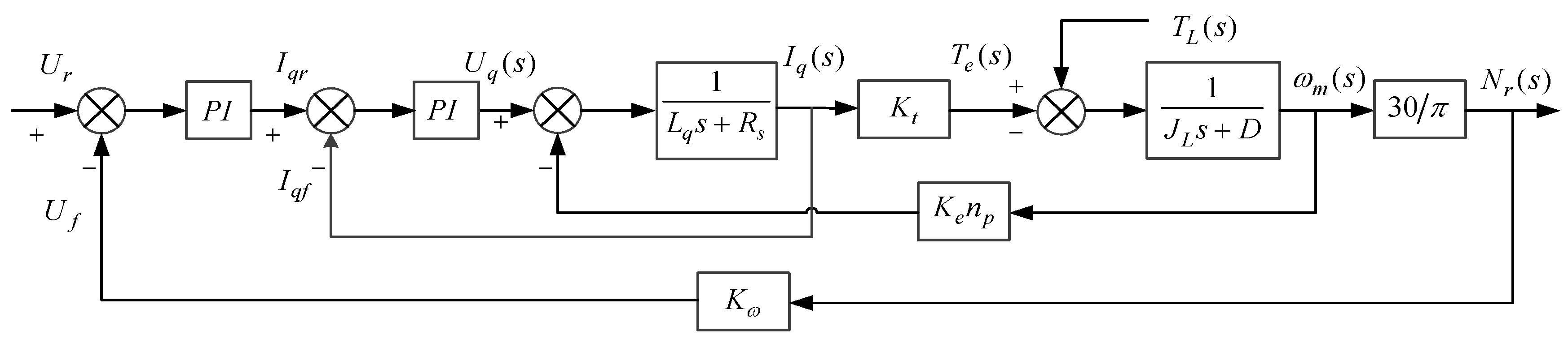
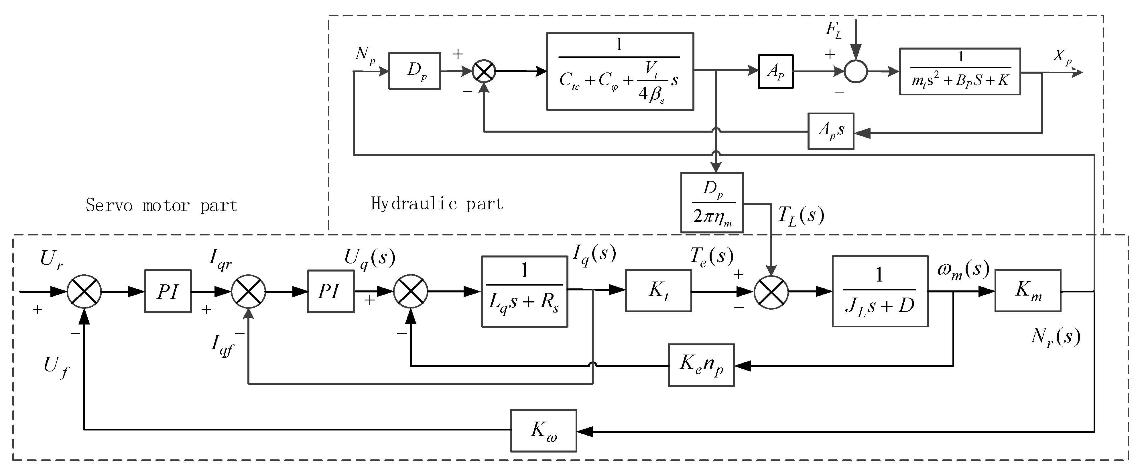
According to the overall control block diagram of the EHA system under low-speed conditions, the fourth-order servo motor system considering speed fluctuation is regarded as the superposition of the two second-order oscillation links, and the pressure pulsation caused by the flow pulsation of the plunger pump is regarded as the first-order inertia link. The transfer function with the given speed ω r e f of the servo motor as the input and the pressure pulsation p L 1 of the plunger pump as the output is written as follows:
p L 1 ( s ) ω r e f ( s ) = ( s 2 ω a 2 + 2 ξ a ω a s + 1 ) ( s 2 ω 1 2 + 2 ξ 1 ω 1 s + 1 ) ( s 2 ω 2 2 + 2 ξ 2 ω 2 s + 1 ) 1 / K L ( V L / K L β e ) s + 1
At this time, the lowest frequency of the two second-order oscillation links is the dominant natural frequency, that is, ω 1 is the dominant natural frequency, and ω 1 can be used to approximately represent the overall natural frequency of the “motor-pump”. Allowing ω 1 = ω n , the expression of the inflation pressure parameter optimization value p 11 of the accumulator absorbing the pressure pulsation is as follows:
p 11 = [ ( k 2 2 k 1 k 4 k 5 k 3 + k 7 ) 2 m a 2 ] V a 0 k A a 2
The undamped natural frequency determines the response speed of the second-order system, and the damping ratio determines the oscillation performance of the second-order system. Increasing the damping ratio will reduce the oscillation, but will increase the response speed of the system. In classical control theory, when the damping ratio a of the second-order oscillation system is 0.707, a better comprehensive performance can be obtained. According to the expression of the accumulator equivalent damping ratio in Equation (26), the optimal value p 12 of the accumulator inflation pressure parameter when ζ = 0.707 is as follows:
p 12 = [ ( B a + c a 1.414 ) 4 k a ] V a 0 k A a 2
Combined with Equations (31) and (32), the optimal selection range of the charging pressure parameters of the accumulator based on ω n and ζ is obtained. This range takes into account the dynamic and static characteristics of the accumulator when absorbing the pressure pulsation, and effectively improves the problem of low-speed instability in the EHA system pressure control.

5. Simulation and Experimental Analysis of Pressure Pulsation in EHA System at Low Speed

Addressing the pressure pulsation problem of the EHA system under low-speed conditions, the fourth section proposes to change the natural frequency and damping ratio of the accumulator by changing the charging pressure, and aims to optimize the design to obtain the optimal parameters for the accumulator to absorb the pressure pulsation. This section verifies the effectiveness of the above conclusions through simulation and experimental analysis.

5.1. Introduction to the Experimental Platform

As shown in Figure 10 and Figure 11, the EHA experimental platform is mainly composed of motion controller, motor driver, signal acquisition module, motor-pump unit and other components. The upper computer transmits the pressure control command to the controller through the ethernet communication mode. The signal acquisition module collects the pressure, temperature and other signals in the system in real time and feeds them back to the controller. The controller obtains the pressure control output signal combined with the high-performance control algorithm program of pressure control, and sends the output signal to the servo driver through the communication mode of a CAN bus, then the motor-pump unit is controlled to accurately control the target pressure in the hydraulic system, which forms a high-performance pressure closed-loop control.

5.2. Analysis of Simulation Results

According to the selection method of the accumulator absorption pressure fluctuation parameters in Section 4, the optimal charging pressure of the accumulator is calculated to be between 4.5 MPa and 5 MPa. In the simulation model established in Section 3, the inflation pressures are set as 2 MPa, 4 MPa, 5 MPa, 10 MPa and 13 Mpa, respectively, and the pressure pulsation signal under low-speed working conditions is given to calculate the natural frequency ω n and damping ratio ζ of the accumulator under different inflation pressures. The output response of the accumulator under different charging pressures is shown in Figure 12.
It can be seen from Figure 12 that different inflation pressures have different absorption effects on the pressure pulsation. When the inflation pressure is 5 MPa, the natural frequency ω n is 1.5 Hz, and the absorption ratio of accumulator to pressure pulsation is 92%. When the inflation pressure is 13 MPa, the natural frequency ω n is 4.25 Hz, and the absorption ratio of accumulator to pressure pulsation is only 89%. Under the different given inflation pressures, the effect of absorbing the pressure pulsation is the best at 5 MPa. When the inflation pressure is 2 MPa and 4 MPa, the effect of absorbing the pressure pulsation is slightly worse. When the inflation pressure is greater than 5 MPa, with the increase of inflation pressure, the damping ratio of the accumulator decreases, and the absorption capacity of the pressure pulsation in the system is worse. Therefore, the optimal inflation pressure range calculated based on accumulator ω n and ζ can optimize the absorption effect of the pressure pulsation of the system.

5.3. Analysis of Experimental Results

Under the pressure step input signal, when the EHA system pressure reaches the steady state, a comparison of the pressure control accuracy of the system under different accumulator charging pressures is undertaken, as shown in Figure 13.
The charging pressure of the accumulator is selected as 2 MPa, 5 MPa, 10 MPa and 13 MPa, respectively. Under a certain step pressure input signal, when the system reaches the steady state, an analysis can be undertaken of the effect of the accumulator absorbing the pressure pulsation under different charging pressures. When the inflation pressure is 5 MPa, the accumulator has the best absorption effect on the pressure pulsation, and the pressure fluctuation of the system is about 2 bar. When the inflation pressure is less than or greater than 5 MPa, the system has a poor absorption effect on the pressure pulsation.
As shown in Figure 12 and Figure 13, under the working condition of low speed, when the system working pressure is same, the pressure pulsation amplitude obtained by the experiment is higher than simulation model, and the pressure pulsation frequency obtained by the experiment is higher than simulation model. This is because the internal friction, leakage, damping and other factors of the system are ignored in the simulation model. It leads to the deviation between the mathematical model and the actual system working state. Therefore, the mathematical model of the system needs to be further improved.
In conclusion, the simulation and experimental results show that the absorption effect of the system pressure pulsation is the best within the optimal charging pressure range calculated based on accumulator ω n and ζ . The calculation formula provides a suitable range for the selection of charging pressures of the accumulator in the EHA system.

6. Conclusions

Addressing the problems of pressure pulsation and flow pulsation in the EHA system at low speed, based on the natural frequency ω n and the damping ratio ζ of the EHA system, calculation of the optimal charging pressure range of the accumulator, and verification of the optimal charging pressure range of the accumulator were performed through a simulation and experiment. First, the mathematical models of the servo motor, metering pump and hydraulic cylinder were established, and the simulation model of the EHA system was demonstrated based on MATLAB/Simulink. Second, the influence mechanism of the speed pulsation of an AC permanent-magnet synchronous motor and the output flow pulsation of a piston pump on the low-speed characteristics of the EHA system were analyzed, and the parameter selection method of eliminating the pressure pulsation of the accumulator based on ω n and ζ was proposed. Finally, the optimal charging pressure of the accumulator was simulated and experimentally analyzed. The simulation and experimental results show that the accumulator charging pressure range calculated by this method can effectively improve the pressure pulsation phenomenon of the EHA system at low speed and improve the dynamic response characteristics of the system.

Author Contributions

Funding acquisition, G.C. and T.Z.; formal analysis, G.C.; methodology, G.Q., G.Y. and H.L.; project administration, G.Y. and C.A.; resources, G.Q., G.C. and H.L.; software, G.Q. and W.C.; writing—original draft, G.Q. and G.C.; writing—review and editing, G.Y. and G.C.; supervision, G.C. and T.Z. All authors have read and agreed to the published version of the manuscript.

Funding

This research was funded by the Key R&D Projects in Hebei Province (No. 20314402D), the Key Project of Science and Technology Research in Hebei Province (No. ZD2020166; No. ZD2021340), the General Project of Natural Science Foundation in Xinjiang Uygur Autonomous Region (No. 2021D01A63) and the Scientific Research Program of the Higher Education Institution of XinJiang (No. XJEDU2021Y050).

Institutional Review Board Statement

Not applicable.

Informed Consent Statement

Not applicable.

Data Availability Statement

Not applicable.

Conflicts of Interest

The authors declare no conflict of interest.

References

  1. Zhang, H.; Ding, L.; Zhang, W.; Li, C. Performance analysis of an electro-hydrostatic actuator with high-pressure load sensing based on fuzzy PID. Mech. Sci. 2021, 12, 529–537. [Google Scholar] [CrossRef]
  2. Kou, F.; Xu, J.; Liu, D.; Zhang, K.; Sun, K. Study on dual sliding mode control of EHA active suspensions. J. China Mech. Eng. 2019, 30, 542. [Google Scholar] [CrossRef]
  3. Zhang, X.; Fu, Y.; Gou, Z. Research on EHA Control Strategy Used in Tank Gun. In Proceedings of the 2020 IEEE International Conference on Advances in Electrical Engineering and Computer Applications (AEECA), Dalian, China, 25–27 August 2020; pp. 1071–1077. [Google Scholar]
  4. Ko, T.; Murotani, K.; Yamamoto, K.; Nakamura, Y. Whole-Body Compliant Motion by Sensor Integration of an EHA-Driven Humanoid Hydra. Int. J. Hum. Robot. 2021, 18, 2150002. [Google Scholar] [CrossRef]
  5. Yan, G.; Jin, Z.; Zhang, T.; Zhao, P. Position Control Study on Pump-Controlled Servomotor for Steam Control Valve. Processes 2021, 9, 221. [Google Scholar] [CrossRef]
  6. Feng, L.; Hui, Z.; Yu, Y.; Xiaokun, L.; Liu, F. Control Moment Gyro Gimble Motor Ultra-Low Velocity Control System Design with Direct-Drive PMSM. In Proceedings of the 2014 International Conference on Mechatronics and Control (ICMC), Jinzhou, China, 3–5 July 2014; pp. 2215–2219. [Google Scholar]
  7. Makino, H.; Nagata, S.; Kosaka, T.; Matsui, N. Spatial harmonics compensation of magnetizing curve model for torque ripple suppression in switched reluctance servo motor. In Proceedings of the 2016 IEEE International Conference on Industrial Technology (ICIT), Taipei, Taiwan, 14–17 March 2016; pp. 198–203. [Google Scholar]
  8. Zhang, W.; Cao, B.; Nan, N.; Li, M.; Chen, Y. An adaptive PID-type sliding mode learning compensation of torque ripple in PMSM position servo systems towards energy efficiency. ISA Trans. 2021, 110, 258–270. [Google Scholar] [CrossRef] [PubMed]
  9. Liu, X.; He, Y.; Mou, Q.; Zhao, J. Analysis and Suppression of Electromagnetic Ripple Torque of Surface-Mounted Permanent Magnet Synchronous Motor with Similar Number of Poles and Slots. In Proceedings of the 2019 22nd International Conference on Electrical Machines and Systems (ICEMS), Harbin, China, 11–14 August 2019; pp. 1–7. [Google Scholar]
  10. Bu, F.; Yang, Z.; Gao, Y.; Pan, Z.; Pu, T.; Degano, M.; Gerada, C. Speed Ripple Reduction of Direct-Drive PMSM Servo System at Low-Speed Operation Using Virtual Cogging Torque Control Method. IEEE Trans. Ind. Electron. 2021, 68, 160–174. [Google Scholar] [CrossRef]
  11. Nos, O.V.; Shtein, D.A.; Leus, G.S.; Nos, N.I.; Abramushkina, E.E.; Ignatev, E.A. The Simplified Control Technique for PMSM Torque Ripple Reduction. In Proceedings of the 2020 21st International Conference of Young Specialists on Micro/Nanotechnologies and Electron Devices (EDM), Chemal, Russian, 29 June–3 July 2020; pp. 475–481. [Google Scholar]
  12. Bu, F.; Xuan, F.; Yang, Z.; Gao, Y.; Pan, Z.; Degano, M.; Gerada, C. Rotor Position Tracking Control for Low Speed Operation of Direct-Drive PMSM Servo System. IEEE/ASME Trans. Mech. 2021, 26, 1129–1139. [Google Scholar] [CrossRef]
  13. Huang, M.; Deng, Y.; Li, H. Fractional-Order Based Resonant Controller for Torque Ripple Suppression of Permanent Magnet Synchronous Motors. In Proceedings of the 2021 IEEE International Conference on Mechatronics (ICM), Chiba, Japan, 7–9 March 2021; pp. 1–6. [Google Scholar]
  14. Asama, J.; Watanabe, J.; Kee, T.T. Development of a Slotless Permanent Magnet Motor with Two-Layer Toroidal Winding for Minimization of Torque Ripple. In Proceedings of the 2021 IEEE International Conference on Mechatronics (ICM), Chiba, Japan, 7–9 March 2021; pp. 1–4. [Google Scholar]
  15. Lin, C.-H.; Ting, J.-C. Novel Nonlinear Backstepping Control of Synchronous Reluctance Motor Drive System for Position Tracking of Periodic Reference Inputs with Torque Ripple Consideration. Int. J. Control. Autom. Syst. 2019, 17, 1–17. [Google Scholar] [CrossRef]
  16. Pan, Y.; Li, Y.; Liang, D. The influence of dynamic swash plate vibration on outlet flow ripple in constant power variable-displacement piston pump. Proc. Inst. Mech. Eng. Part C J. Mech. Eng. Sci. 2019, 233, 4914–4933. [Google Scholar] [CrossRef]
  17. Wang, B.; Wang, Y. The Research on Flow Pulsation Characteristics of Axial Piston Pump. In Proceedings of the Seventh International Conference on Electronics and Information Engineering, Nanjing, China, 17–18 September 2016; Volume 10322, p. 103223. [Google Scholar]
  18. Liu, X.; Cao, S.; Shi, W.; He, X. Analysis and design of a water pump with accumulators absorbing pressure pulsation in high-velocity water-jet propulsion system. J. Mar. Sci. Technol. 2015, 20, 551–558. [Google Scholar] [CrossRef]
  19. Zhang, Z.; Cao, S.; Wang, H.; Luo, X.; Deng, J.; Zhu, Y. The approach on reducing the pressure pulsation and vibration of seawater piston pump through integrating a group of accumulators. Ocean Eng. 2019, 173, 319–330. [Google Scholar] [CrossRef]
  20. Ouyang, X.-P.; Fang, X. An investigation into the swash plate vibration and pressure pulsation of piston pumps based on full fluid-structure interactions. J. Zhejiang Univ. A 2016, 17, 202–214. [Google Scholar] [CrossRef] [Green Version]
  21. Xu, B.; Hu, M.; Zhang, J. Impact of typical steady-state conditions and transient conditions on flow ripple and its test accuracy for axial piston pump. Chin. J. Mech. Eng. 2015, 28, 1012–1022. [Google Scholar] [CrossRef]
  22. Zhang, H. Cavitation Effect to the Hydraulic Piston Pump Flow Pulsation. Appl. Mech. Mater. 2014, 599–601, 230–236. [Google Scholar] [CrossRef]
  23. Zhang, J.; Sun, H.; Dou, X.; Kang, S.; Kong, X. Analysis of influencing factors on flow pulsation of inline type double row axial piston pump. J. Transact. Beijing Inst. Technol. 2020, 40, 481–485. [Google Scholar] [CrossRef]
  24. Zhang, T. Simulation Analysis of Pressure Pulsation Function in Hydraulic Piston Pump. J. Vib. Meas. Diagn. 2016, 36, 841–844. [Google Scholar]
Figure 1. Electro-hydrostatic actuator (EHA) hydraulic schematic: 1—servo motor; 2—fixed displacement two-way hydraulic pump; 3—temperature sensor; 4—pressure relay; 5—pressure joint; 6—one-way valve; 7—fill oil accumulator; 8—high-pressure relief valve; 9—low-pressure relief valve; 10—pressure sensor; 11—unloading valve; 12—quick release coupling; and 13—pressure pulsation absorber accumulator.
Processes 09 01903 g001
Figure 2. Control block diagram of servo motor speed control system: K p is the gain of the velocity loop; K i is the gain of the current loop; U r is the given signal; K ω is the coefficient of the servo motor speed; and N r is the speed of motor.
Processes 09 01903 g002
Figure 3. Simulation model of three-phase permanent-magnet synchronous motor (PMSM) vector control.
Processes 09 01903 g003
Figure 4. Simulation model of SVPWM control algorithm.
Processes 09 01903 g004
Figure 5. EHA hydraulic system control block diagram.
Processes 09 01903 g005
Figure 6. EHA system transfer function block diagram.
Processes 09 01903 g006
Figure 7. EHA system simulation model.
Processes 09 01903 g007
Figure 8. Structural schematic diagram of axial piston pump: 1—swashplate; 2—plunger; 3—cylinder block; 4—port plate; and 5—transmission shaft.
Processes 09 01903 g008
Figure 9. Gas spring-damping model.
Processes 09 01903 g009
Figure 10. EHA electrical control system.
Processes 09 01903 g010
Figure 11. Hydraulic control unit.
Processes 09 01903 g011
Figure 12. Simulated pressure output curve of accumulator under different inflation pressure.
Processes 09 01903 g012
Figure 13. Experimental pressure output curve of accumulator under different inflation pressures.
Processes 09 01903 g013
Table 1. Parameter setting of speed loop and current loop.
ParametersSpeedPi-IqPi-Id
Proportional gain (Kp)0.1413.25.775
Integral gain (Ki)71053.81053.8
Feedback gain (Ba)0.013
Output limits[−30, 30][−161.6, 161.6][−161.6, 161.6]
Output initial value000
Sample time10−510−510−5
Table 2. EHA simulation model parameters.
SymbolPhysical SignificanceParameterUnit
K i l p Internal leakage coefficient of pump10−13(m3/s)/Pa
K e l p External leakage coefficient of pump10−13(m3/s)/Pa
D Displacement of pump1.5mL/r
K i l j Internal leakage coefficient of cylinder10−13(m3/s)/Pa
K v p Piston damping coefficient150N/(m/s)
k Air polytropic exponent1.3
F s Static friction25N
F c Sliding friction15N
V 10 ,   V 20 Initial volume of hydraulic cylinder chamber450mL
B Bulk modulus of oil6.5 × 108N/m2
A Effective piston area71cm2
M Payload mass2000Kg
V g i Accumulator initial gas volume200ml
P a i Accumulator initial pressure3MP
V a i Accumulator initial oil volume200ml
Publisher’s Note: MDPI stays neutral with regard to jurisdictional claims in published maps and institutional affiliations.

