Article

Renewable Hydrogen Production from Butanol Steam Reforming over Nickel Catalysts Promoted by Lanthanides

by
João Paulo da S. Q. Menezes
,
Gabriel M. Guimarães
,
Mônica A. P. da Silva
and
Mariana M. V. M. Souza
*
Centro de Tecnologia, Escola de Química, Universidade Federal do Rio de Janeiro (UFRJ), Bloco E, Rio de Janeiro 21941-909, RJ, Brazil
*
Author to whom correspondence should be addressed.
Processes 2021, 9(10), 1815; https://doi.org/10.3390/pr9101815
Submission received: 15 September 2021 / Revised: 7 October 2021 / Accepted: 8 October 2021 / Published: 13 October 2021

Abstract

:
Hydrogen is mainly produced by steam reforming of natural gas, a nonrenewable resource. Alternative and renewable routes for hydrogen production play an important role in reducing dependence on oil and minimizing the emission of greenhouse gases. In this work, butanol, a model compound of bio-oil, was employed for hydrogen production by steam reforming. The reaction was evaluated for 30 h in a tubular quartz reactor at 500 °C, atmospheric pressure, GHSV of 500,000 h−1, and an aqueous solution feed of 10% v/v butanol. For this reaction, catalysts with 20 wt.% NiO were prepared by wet impregnation using three supports: γ-alumina and alumina modified with 10 wt.% of cerium and lanthanum oxides. Both promoters increased the reduction degree of the catalysts and decreased catalyst acidity, which is closely related to coke formation and deactivation. Ni/La2O3–Al2O3 presented a higher nickel dispersion (14.6%) which, combined with other properties, led to a higher stability, higher mean hydrogen yield (71%), and lower coke formation per mass (56%). On the other hand, the nonpromoted catalyst suffered a significant deactivation associated with coke formation favored by its highest acidity (3.1 µmol m²).

Graphical Abstract

1. Introduction

Nowadays, most of the world’s energy production is dependent on fossil fuels, whose burning is related to greenhouse gases emission, such as carbon dioxide and methane. Thus, the search for alternative and cleaner fuels is essential because it plays an important role in reducing the effects of global warming. In this context, hydrogen is a promising fuel, as its use in fuel cells produces only water as a byproduct. Furthermore, fuel cells present higher energy efficiency in comparison with conventional combustion engines [1].
However, the main commercial route for hydrogen production is natural gas steam reforming, which is also dependent on fossil fuels. This route accounts for 48% of the world’s hydrogen supply [2]. In this way, new routes employing renewable resources such as biomass for its production should be developed to make the whole hydrogen production process and use cleaner and sustainable.
In this context, bio-oil is an attractive candidate for hydrogen production because it is produced in great amounts by fast biomass pyrolysis and its use would contribute to develop an integrated biorefinery. Bio-oil is composed of an organic phase (pyrolytic lignin) and an aqueous phase with more than 200 compounds [3]. Oasmaa and Meier [4] verified that the alcohol present in greater amount in the aqueous phase of bio-oil is n-butanol. Thus, in this work, butanol was employed as a model compound of bio-oil aqueous phase.
Butanol steam reforming occurs in two steps: first, butanol reacts with steam producing synthesis gas (CO and H2), presented in Equation (1). This reaction is highly endothermic and promotes an increase in gas volume. Thus, it is favored at high temperatures and low pressures [5]. In the second step, carbon monoxide reacts with water to produce more hydrogen and carbon dioxide, which is presented in Equation (2). This is called shift reaction, and it is favored at low temperatures due to its exothermicity [5].
C₄H₉OH + 3 H₂O ↔ 8 H₂ + 4 CO
CO + H₂O ↔ CO₂ + H₂
As reported in the literature, nickel supported on alumina is widely employed as a catalyst for butanol steam reforming [1,6,7,8]. This is due to the high nickel activity in breaking C–C, C–H, and O–H bonds, and its lower cost compared to noble metals [9]. Furthermore, the high specific area of alumina provides a good-quality nickel dispersion. However, alumina acid sites contribute to coke formation by dehydration, polymerization, and cracking reactions [10]. Coke deposition on nickel surface is one of the main reasons for catalyst deactivation during time on stream. Thus, the addition of basic promoters such as lanthana and ceria could decrease catalyst acidity and contribute to minimizing coke formation. Furthermore, the literature reports that basic promoters enhance shift reaction, as CO adsorption and water dissociation are promoted by weak basic sites [11].
Moreover, as reported in the literature, the rare-earth oxides, such as ceria and lanthana, favor the coke gasification and improve the redox reversibility of the metallic phase. Ceria presents high oxygen mobility [1], which is related to its capacity to store, release, and transport oxygen [12]. Lanthana is a strong basic promoter and promotes coke removal from catalyst surface due to the formation of lanthanum carbonates [13,14].
Santamaria et al. [15] reported that lanthana addition on a nickel/alumina catalyst improved the hydrogen yield and catalyst stability in biomass pyrolysis-reforming. This behavior was explained by the capability of lanthana promoter for adsorbing water, regenerating, and maintaining the catalyst activity.
Bizkarra et al. [7] studied the effect of lanthana and ceria addition on nickel/alumina catalyst for butanol steam reforming. They reported that ceria increased the activity and hydrogen yield, while lanthana containing catalysts presented a worse catalytic performance in most conditions evaluated. However, the reactions were carried out for only 4 h because their work focused on comparing the performances of the different supports under different reaction conditions. Thus, the development of catalyst formulation strategies for minimizing coke formation and producing a stable catalyst over a long time on stream is still needed in the literature. The present work is a contribution to this subject.
Patel and Patel [16] concluded, in their review of butanol reforming reaction, that the main drawback of the process is the development of catalysts that provide high-purity hydrogen for a prolonged time, suppressing undesirable reactions. Furthermore, they reported that the catalyst’s ability to remain active for a sufficient time is essential for commercial implementation.
Thus, the main objective of our work is to determine the role of ceria and lanthana promoters on the catalytic behavior and stability of nickel/alumina catalyst throughout a long reaction time (30 h). The catalytic behavior and the amount of coke formed during the reaction were correlated with the catalyst properties (metal dispersion, reducibility, and acidity).

2. Materials and Methods

2.1. Catalyst Preparation

The γ-Al2O3 support was prepared by calcination of a commercial boehmite (Sasol) at 500 °C for 3 h with a 60 mL min−1 air flow and heating rate of 10 °C min−1. The promoted supports were prepared by wet impregnation of cerium nitrate (Ce(NO3)3.6H2O) and lanthanum nitrate (La(NO3)3.6H2O), respectively, on γ-Al2O3. This step was followed by drying overnight at 100 °C and calcination under the same conditions mentioned before. The precursors were weighed to provide a support with 10 wt.% of the oxide promoter.
The synthesis of nickel catalysts occurred by wet impregnation of nickel nitrate (Ni(NO3)2.6H2O-Vetec) on the prepared supports, providing 20 wt.% NiO after drying and calcination under the prior described conditions. The catalysts were named as NiAl, NiCeAl, and NiLaAl.
All wet impregnation procedures were carried out in a rotary evaporator in two steps. First, the suspension at room temperature was stirred at 120 rpm for 1 h to promote the contact between the liquid solution and the solid material. Then, the samples were heated up to 80 °C, and a vacuum was created to promote water removal. The wet impregnation methodology of ceria and lanthana promoters on alumina and nickel precursor on the supports was similar to the methodology reported by Bizkarra et al. [7].

2.2. Catalysts Characterization

The chemical compositions of the catalysts and the supports were measured by X-ray fluorescence (XRF) analysis performed in a Rigaku Primini spectrometer equipped with a palladium X-ray tube.
Textural properties of the materials were obtained by N2 physisorption using equipment Tristar 3000 from Micromeritics. Prior to the analysis, the samples were dried and outgassed at 300 °C under vacuum. Specific area was measured using the Brunauer–Emmett–Teller (BET) method, while pore volume and size were calculated using the Barret, Joyner, and Halenda (BJH) method, using the desorption isotherm.
Samples of the supports and the catalysts in different stages (calcined, reduced, and after reaction test) were submitted to X-ray diffraction (XRD) analysis performed in a Rigaku Miniflex II diffractometer coupled with a graphite monochromator using CuKα radiation (30 kV and 15 mA). The analysis was performed with a step of 0.05°, counting time of 1 s for step and over a 2θ range of 5–90°. Beyond identifying crystalline phases, the XRD profiles of reduced samples were used to measure Ni crystallite size by Scherrer equation. The Ni peak at 51° was chosen for this proposal due to less interference with the support peaks. Ni crystallite size was also used to determine nickel dispersion (D) calculated by Anderson correlation [17], presented in Equation (3), assuming spherical particles.
D = 6   V m D h k l A m
where Vm, D h k l , and Am are, respectively, the nickel atomic volume (0.0109 nm³), the Ni crystallite size (nm), and the surface area of a single nickel atom (0.0649 nm²).
Temperature-programmed reduction (TPR) of calcined catalysts was performed to evaluate the reduction profile of NiO to metallic Ni. For the analysis, 50 mg of the calcined catalysts were weighed and dried at 150 °C and 30 mL min−1 of argon flow in a quartz reactor. Then, the temperature was raised to 1000 °C at 10 °C min−1 and using 30 mL min−1 of a mixture 1.8% H2/Ar, which promoted the NiO reduction. The sign of hydrogen consumption was monitored by a thermal conductivity detector (TCD) coupled to the gas outlet. The reduction degree was measured as the ratio between hydrogen consumed for reduction, calculated by the area under TPR curves, and theoretical hydrogen consumed if all nickel species were reduced, determined by the stoichiometry of NiO reduction reaction (Equation (4)).
N i O + H 2 N i + H 2 O  
The acidity of catalysts was determined by temperature-programmed desorption of ammonia (TPD-NH3). Before analysis, 150 mg of the calcined catalyst were weighed and dried in a quartz reactor under the same conditions mentioned in the TPR analysis. Then, NH3 adsorption was performed at 70 °C for 30 min with 30 mL min−1 of a mixture of 4% NH3/He. Afterwards, physisorbed ammonia was removed with 30 mL min−1 of helium flow for 1 h. Finally, the chemisorbed ammonia was desorbed up to 800 °C with a heating rate of 20 °C min−1 under 30 mL min−1 of helium flow. Ammonia sign was evaluated by a QMG-220 Pfeiffer mass spectrometer, monitoring the ratio m/z = 15.
Coke formation on spent catalysts was analyzed by thermogravimetric (TGA) and differential thermal (DTA) analysis, using a TA SDT Q600 equipment. The silicon carbide was firstly separated from the catalyst with a sieve of 150 mesh. Then, masses between 3 and 10 mg were weighed on a balance inside the equipment and heated at 10 °C min−1 to 1000 °C using a synthetic air flow of 50 mL min−1.
The morphology of coke deposits on spent catalysts was evaluated by a scanning electron microscope Hitachi TM-3030. Backscattering and secondary electrons with an acceleration voltage of 15 kV were used to perform the analysis.

2.3. Butanol Steam Reforming Reaction

Before the beginning of the reaction, the catalyst (150 mg) and silicon carbide (750 mg) were mixed in a proportion of 1:5. The SiC presented particle size in the range of 115 and 80 mesh. Then, the catalyst was reduced in situ with 30 mL min−1 of H2 and 60 mL min−1 of N2 in a quartz tubular reactor. The reduction was conducted with a heating rate of 10 °C min−1 up to 800 °C, keeping this temperature for 30 min.
Patel and Patel [16] reported that previous works of butanol steam reforming using Ni catalysts generally employed atmospheric pressure and temperature range of 500–650 °C. Moreover, they affirmed that low temperatures and low steam/carbon ratio in feed favor coke formation. Therefore, in this work, the reaction conditions were chosen in order to enhance coke deposition and promote deactivation. In this way, we could assess whether the catalysts were active for long periods even under adverse conditions.
Butanol steam reforming reaction was carried out during 30 h in the same tubular reactor at 500 °C, at atmospheric pressure, GHSV of 500,000 h−1, using an aqueous solution of 10% v/v of butanol in the feed and a steam/carbon molar ratio of 11.4. It should be noted that butanol presents only moderate solubility in water at 20 °C (90 g mL−1); thus, in the present work, approximately the maximum butanol concentration in solution was employed to guarantee a complete solubility. Helium was employed as the carrier gas with a flow rate of 127.6 mL min−1, calculated to represent 20% v/v of total inlet gas flow (637.8 mL min−1). The total inlet gas flow and pump flow, aiming at the specified space GHSV, was calculated using a Gibbs reactor and Uniquac package by Hysys 3.2 software. The sample volume was approximately 0.077 mL. Space velocity (GHSV) was determined as the ratio between total inlet gas flow and sample volume.
The feed solution was pumped (Eldex 1SAM) with a flow rate of 0.269 mL min−1 and passed through an evaporator at 200 °C, which provided its evaporation under helium flow. The condensation was avoided by keeping the lines and valves at 200 °C. The reactor outlet was connected with a condenser maintained at 3 °C, where the separation between the liquid and gas phases occurred. The liquid phase, collected hourly in the first 8 h and last 7 h of reaction, was quantified by high-performance liquid chromatography (HPLC) (Shimadzu Prominence). The column employed was a Bio-Rad Aminex HPX-87H with a flow of 0.01 M H2SO4 at 0.6 mL min−1. The peaks were evaluated using UV and refractive index detectors. The column was operated inside an oven kept at 30 °C.
The gas chromatography (GC) (Shimadzu GC-2014), using helium as carrier gas, was employed to analyze the gas phase. The equipment presented a column (Carboxen 1010 and thermal conductivity (TCD) and flame ionization (FID) detectors.
The parameters used to evaluate catalyst performance are defined in the equations below, based on the stoichiometry of the global butanol steam reforming reaction (Equation (5)).
C 4 H 9 OH + 7 H 2 O 4 CO 2 + 12 H 2
  • Global conversion (X), Equation (6):
    X   ( % ) = N B u t a n o l I n l e t ( m o l / h ) N B u t a n o l O u t l e t ( m o l / h ) N B u t a n o l I n l e t ( m o l / h ) × 100
  • Conversion to gas (XG), Equation (7):
    X G ( % ) = C a r b o n   m o l e s   i n   g a s   p h a s e C a r b o n   m o l e s   i n   f e e d × 100
  • Hydrogen yield, Equation (8):
    Y H 2 ( % ) = N H 2 O u t l e t ( m o l / h ) 12 × N B u t a n o l I n l e t ( m o l / h ) × 100
  • CO, CO2 or CH4 yields, Equation (9):
    Y j ( % ) = N j O u t l e t ( m o l / h ) 12 × N B u t a n o l I n l e t ( m o l / h ) × 100  
    where “j”: CO, CO2, or CH4.

3. Results and Discussion

3.1. Catalyst Characterization

Table 1 shows the chemical composition measured by XRF and textural properties measured by N2 physisorption of the catalysts and their respective supports. It was observed that measured and nominal compositions are similar, considering the semiquantitative nature of the analysis, because fluorescent emissions from elements can interfere with each other.
There was a decrease in BET surface area by the addition of NiO and the promoters (CeO2 and La2O3). This tendency was expected due to the low BET area of these oxides and because its addition decreases the alumina content in the catalyst composition. Moreover, a decrease in pore volume was observed by ceria and lanthana addition from 0.37 to 0.26–0.25 cm3 g−1, which may indicate a recovering of alumina pores during the wet impregnation. Lanthana addition led to the highest decrease in BET area, from 201 to 88.5 m2 g−1, indicating a higher dispersion of this promoter on alumina surface.
Mortola et al. [18] also reported a decrease in BET surface area and pore volume by the addition of 12 wt.% La2O3 and 12 wt.% CeO2 on alumina support due to the blockage of alumina smaller pores and the incorporation of lanthanum or cerium into the alumina network. In their study, the addition of lanthana caused the greatest decrease in surface area, from 182 to 104 m2 g−1, and in pore volume, from 0.29 to 0.12 cm3 g−1, which is in accordance with this work. They explained this behavior by a strong interaction between alumina and lanthana during synthesis. Mazumder et al. [19] attributed the blockage of alumina pores to the formation of LaAlO3 species due to solid interaction at high temperatures between alumina and lanthana.
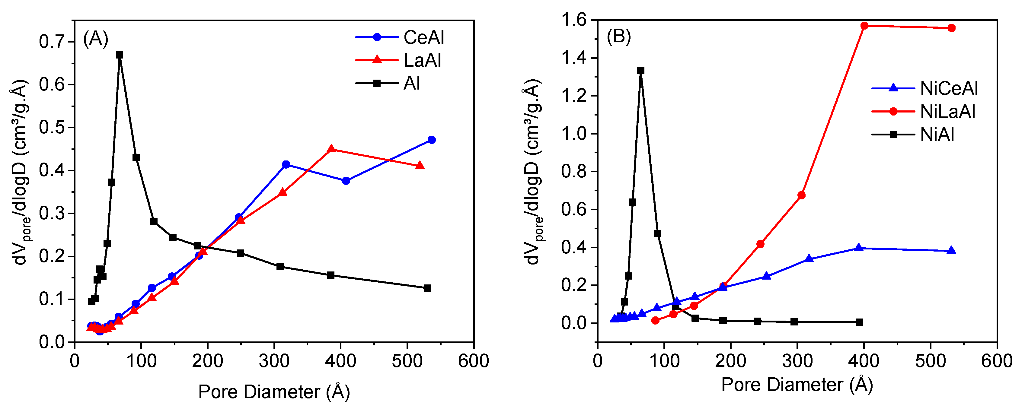
Ceria and lanthana incorporation on alumina also significantly increased mean pore size, from 81.7 to 177.4 and 186.0 Å, respectively. This behavior may be explained by the larger atomic radii of cerium and lanthanum, compared to aluminum, which promotes an expansion of the pores during impregnation and calcination. In addition, the nickel incorporation in the promoted supports also caused an additional increase in pore size, especially for the NiLaAl catalyst. Mazumder et al. [19] also reported an increase in pore diameter from 73.64 to 136.22 Å after 20 wt.% Ni loading on 10 wt.% La2O3–Al2O3 support. They attributed this effect to the thermal sintering and inclusion of large-size metal particles into the support pores.
Figure 1 shows the distribution of pore size for the supports and catalysts. It is observed that the nonpromoted catalyst and support presented a narrower distribution of pores, mostly centered between 0 and 100 Å. The addition of both promoters shifted the distribution towards larger pore sizes, which corroborates the hypothesis that small alumina pores are clogged by ceria and lanthana. Moreover, there was an expansion of pores, mainly by nickel incorporation on lanthana-modified support, as mentioned earlier.
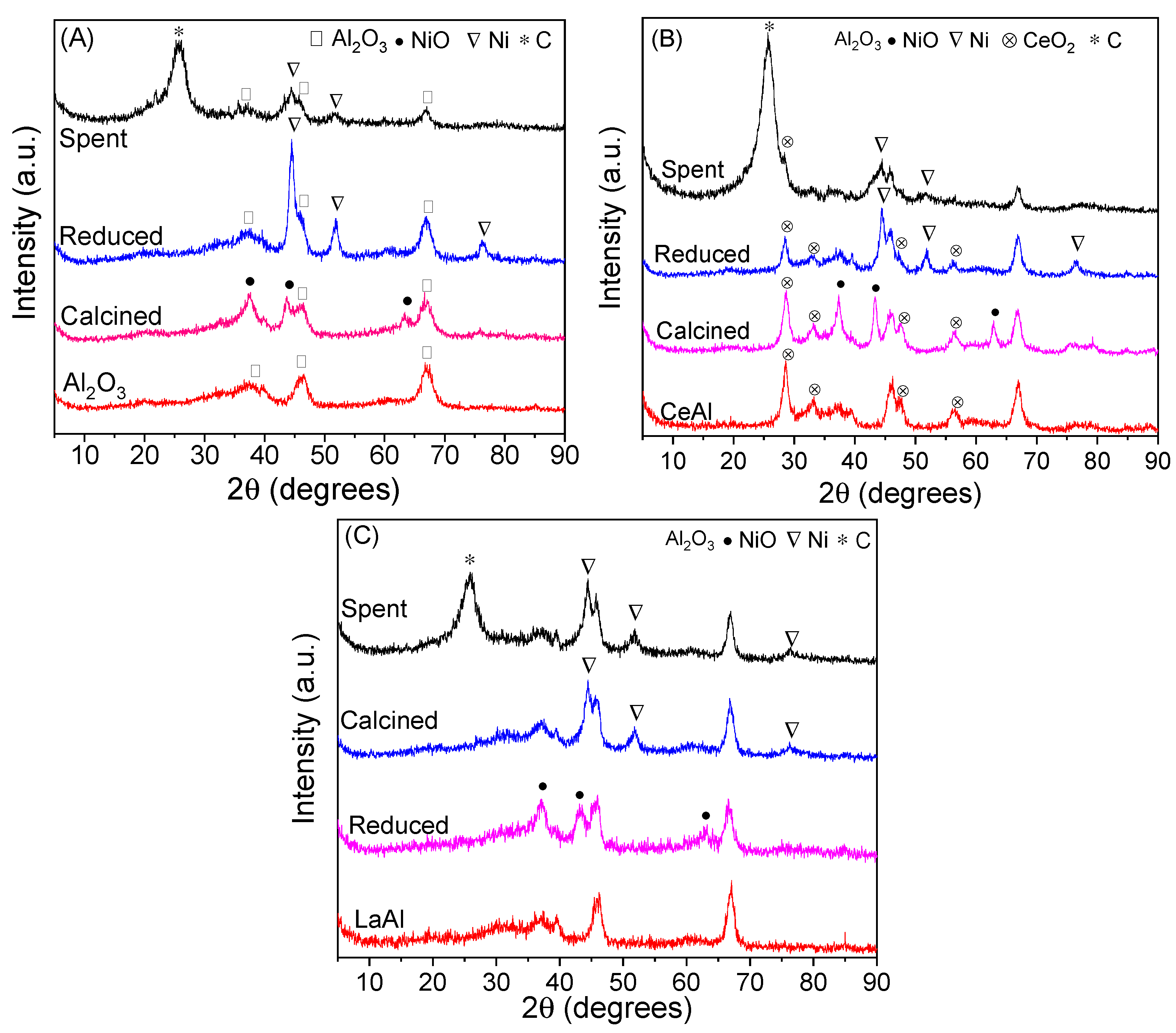
Figure 2 presents the XRD diffractograms of the supports, calcined, reduced, and spent catalysts. Peaks related to alumina (γ-Al2O3) are observed in all diffractograms at 2θ equal to 37.6 (3 1 1), 45.9 (4 0 0), and 66.1° (4 4 0) (JCPDS 10-425). It is also observed NiO peaks at 2θ equal to 37.3 (1 0 1), 43.3 (0 1 2), and 62.9° (1 0 4) (JCPDS 47-1049) in all calcined catalysts and peaks related with Ni metallic phase at 44.5 (1 1 1), 51.8 (2 0 0), and 76.5° (2 2 0) (JCPDS 04-0850) in all reduced catalysts. This indicates a good efficiency of calcination and reduction steps. Spent catalysts presented the peaks related to nickel phase and no peaks related to NiO, indicating a good stability of Ni phase during the reaction. Furthermore, a peak at 26° (1 1 1) (JCPDS 75-0444) on the spent catalysts is associated with carbon deposits produced during the reaction. This peak is most intense for NiCeAl catalyst, which suggests a high coke deposit, corroborated by TGA analysis. Coke crystallite size, reported in Table 2, is similar for all catalysts.
Peaks related to CeO2 at 28.6 (1 1 1), 33.2 (2 0 0), 47.8 (2 2 0) and 56.4° (3 1 1) (JCPDS 34-0394) are observed in all stages of NiCeAl catalyst presented in Figure 2B. In contrast, no peaks associated with lanthana were detected in NiLaAl profiles, reported in Figure 2C. This result corroborates a better dispersion of lanthana on alumina in comparison with ceria. Mazumder et al. [19] also did not observe any peaks related to lanthana on a 10 wt.% La2O3–Al2O3 support. Thus, they reported that lanthana species were either highly dispersed on alumina surface as an amorphous phase or incorporated into the pore network of alumina. Iriondo et al. [12] studied the addition of 10 wt.% ceria on Ni/Al2O3 catalyst and also detected peaks related to CeO2 with fluorite structure at the same positions mentioned in this work. They also mentioned the ceria capacity to form aggregates, which could decrease its dispersion on alumina.
Ni crystallite size, calculated by Scherrer equation using the peak centered at 51.8°, and nickel dispersion, obtained by Anderson correlation, are shown in Table 2. Considering the analysis error, it was observed that the addition of both promoters did not significantly change the nickel crystallite size compared with NiAl catalyst. However, NiLaAl presented a smaller crystallite size and higher dispersion than NiCeAl, attributed to a better interaction with nickel species provided by small lanthanum particles dispersed on the support. Big ceria crystals (8.8 ± 0.8 nm), calculated using the peak centered at 28.6° of the reduced sample, should provide a weaker interaction with nickel.
Iriondo et al. [12] suggested that for a 20 wt.% CeO2 promotion on Ni/Al2O3, ceria tends to interact with alumina instead of nickel, decreasing stability of the nickel phase and reducing its dispersion. They also reported that large ceria crystallites could hinder the interaction between ceria and nickel.
Dan et al. [20] reported that 6 wt.% lanthana on nickel/alumina catalyst increased nickel dispersion measured by H2 chemisorption approximately three times. In contrast, for 6 wt.% ceria addition, the dispersion was very similar compared to the nonpromoted catalyst. Furthermore, nickel crystallite size measured from diffractograms was decreased from 10 to 6.7 nm by lanthana addition, which agrees with the values presented in this work. However, this tendency of reducing was not confirmed in this work due to the analysis error.
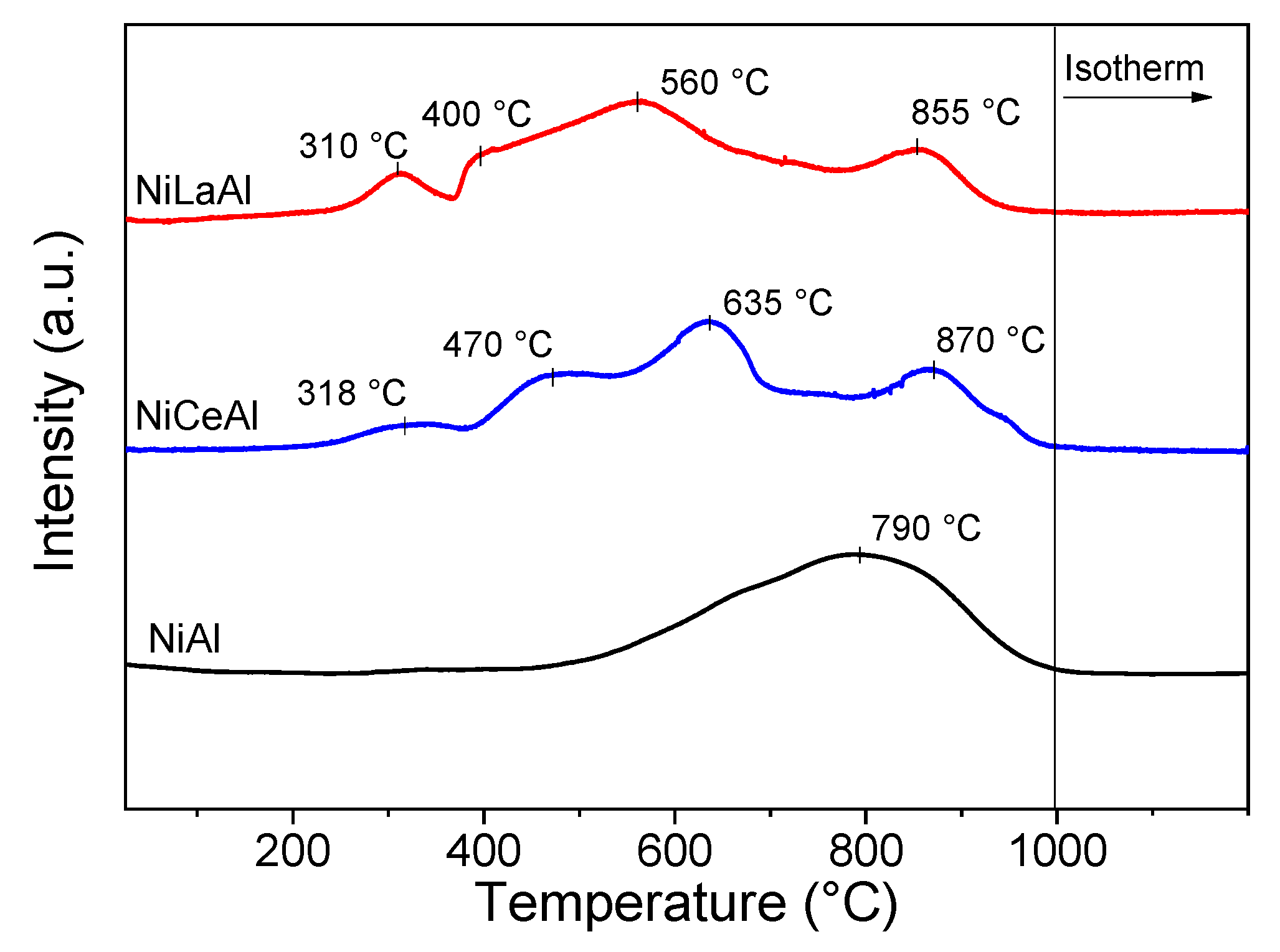
Figure 3 shows TPR profiles of the catalysts. NiAl presented only a broad peak centered at 790 °C, associated with the reduction of nickel aluminate species (NiAl2O4). According to Rynkowski et al. [21], nickel aluminate species reduce at temperatures above 700 °C.
The addition of both promoters shifted the curves to lower temperatures, indicating that these promoters decrease the formation of aluminate species on calcined catalysts. This hypothesis is confirmed by the increase in reduction degree with lanthana and ceria addition reported in Table 2, as nickel aluminate is difficult to reduce. NiCeAl and NiLaAl presented four reduction peaks. The first, centered at 310–318 °C, is related to NiO with poor interaction with the support. The peaks centered at 400–470 °C and 560–635 °C are associated with NiO species in the pores with intermediate and strong interaction with the promoted support, respectively, and the last peak, centered at 855–870 °C, is related to nickel aluminate reduction.
Mazumder et al. [19] reported that lanthana addition (5 wt.%) on Ni/Al2O3 shifted TPR curves to lower temperatures, indicating that this promoter decreases Ni–Al2O3 interaction. Furthermore, by adding lanthana, they noticed a small peak at around 390 °C related to the reduction of dispersed NiO species on the support surface, in line with our findings. The reducibility was also increased from 90 to 94% by La2O3 incorporation, suggesting a higher proportion of easily reducible species and diminished formation of nickel aluminate species. Dan et al. [20] also reported the same tendency on TPR curves by adding lanthana on nickel/alumina catalyst. This promoter extends the proportion of NiOx species in weak interaction with the support.
Figure 4 shows the results of ammonia desorption by increasing temperature. All catalysts presented only one broad peak, centered at 240–250 °C, related to the majority presence of weak acid sites, according to the literature [22]. However, the temperature range in which the desorption peak is centered is narrower for NiLaAl, indicating that lanthana addition decreased the strength of catalyst acid sites.
The acidity expressed by mass and per specific area is summarized in Table 2. A significant decrease of catalyst acidity was observed by both promoter additions, especially by lanthana, which promoted a reduction from 3.1 to 0.5 μmol NH3 m−2. This result was expected due to the basic nature of lanthanide oxides. Furthermore, the greatest decrease observed for NiLaAl may be associated with the highest dispersion of lanthana on alumina support, and the highest coverage of alumina pores, titrating the acid sites. Mazunder et al. [19] found that 5 wt.% La2O3 addition on γ-Al2O3 support decreased acidity from 370 to 251 µmol g−1. They also reported that some of the lanthana basic sites are employed to neutralize the acid sites of γ-Al2O3. Montini et al. [23] reported that lanthana and ceria incorporation on Pt/Al2O3 catalyst decreased the amount of desorbed NH3, together with a shift to lower temperatures, indicating a reduction in acid strength. This behavior was more pronounced for lanthana incorporation due to its higher dispersion on alumina, which agrees with this work.

3.2. Catalytic Tests

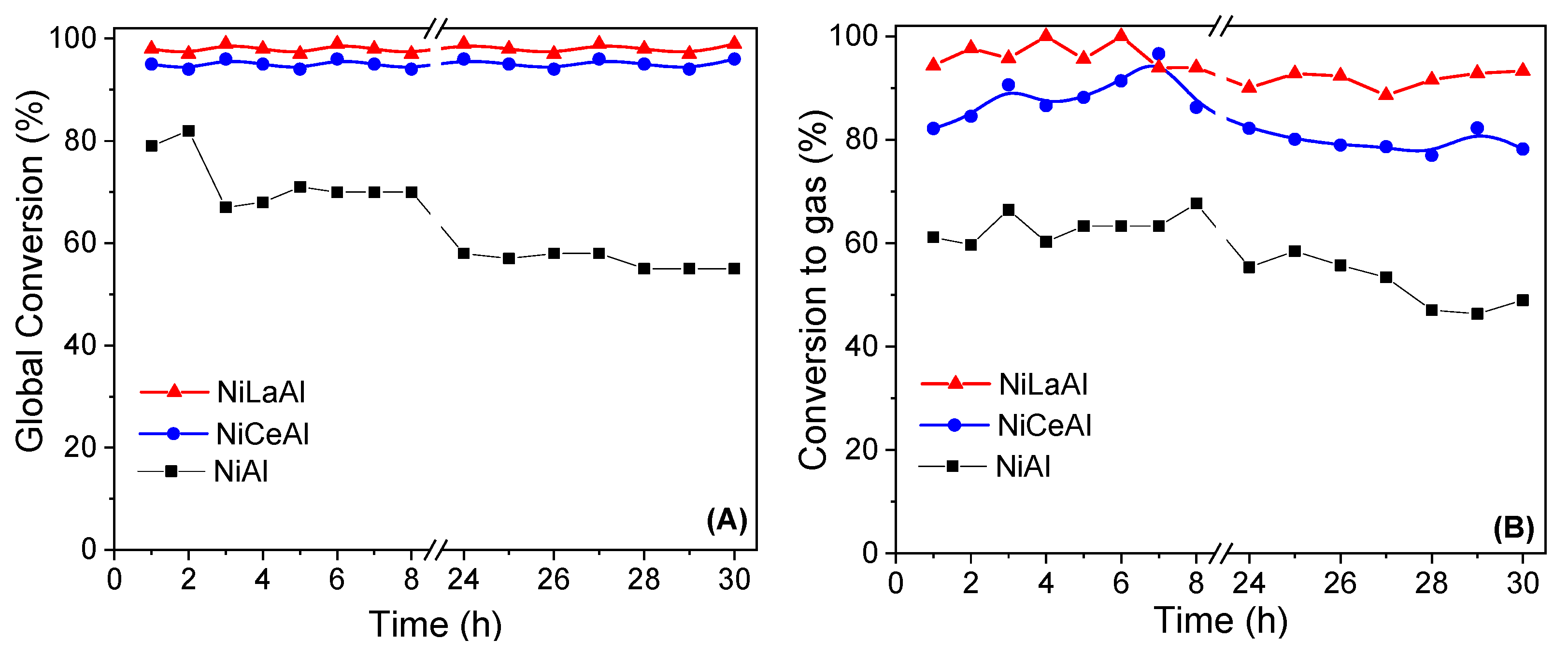
Figure 5 shows the results of global conversion and conversion to gas for butanol steam reforming reaction at 500 °C during 30 h of time on stream. NiAl presented the lowest activity in comparison with the promoted catalysts. Moreover, the nonpromoted catalyst suffered the most severe deactivation, as conversion decreased from 79 to 55% and conversion to gas dropped from 61 to 49%. This indicates that both promoters increased the stability of nickel active phase, especially the lanthana. Furthermore, the deactivation may be explained by coke deposition on nickel surface, favored by alumina acid sites [10].
NiLaAl catalyst presented the best performance, as its global conversion remained practically constant at 100% and its conversion to gas suffered small variation in the range of 90–100%. Moreover, the discrepancy between global conversion and conversion to gas is low during all reactions, which indicates that parallel reactions of coke and liquid byproducts formation are less important for this catalyst, providing its best stability. These results agree with its highest nickel dispersion and reducibility, which increased the availability of nickel metallic active sites, and with its lowest acidity, decreasing the population of acid sites for parallel reactions.
On the other hand, the ceria promotion did not present the same benefits in terms of catalytic performance. Ceria was less dispersed on the support, and its interaction with nickel was poor, leading to the lowest nickel dispersion. For NiCeAl catalyst, the global conversion remained constant at approximately 95%; however, conversion to gas decreased from 95% at the seventh hour to 78% at the end of the reaction. It was observed that a reduction in conversion to gas did not accompany the drop in global conversion. These conversion profiles indicated that the activity for parallel reactions, mainly coke formation, increased throughout time on stream.
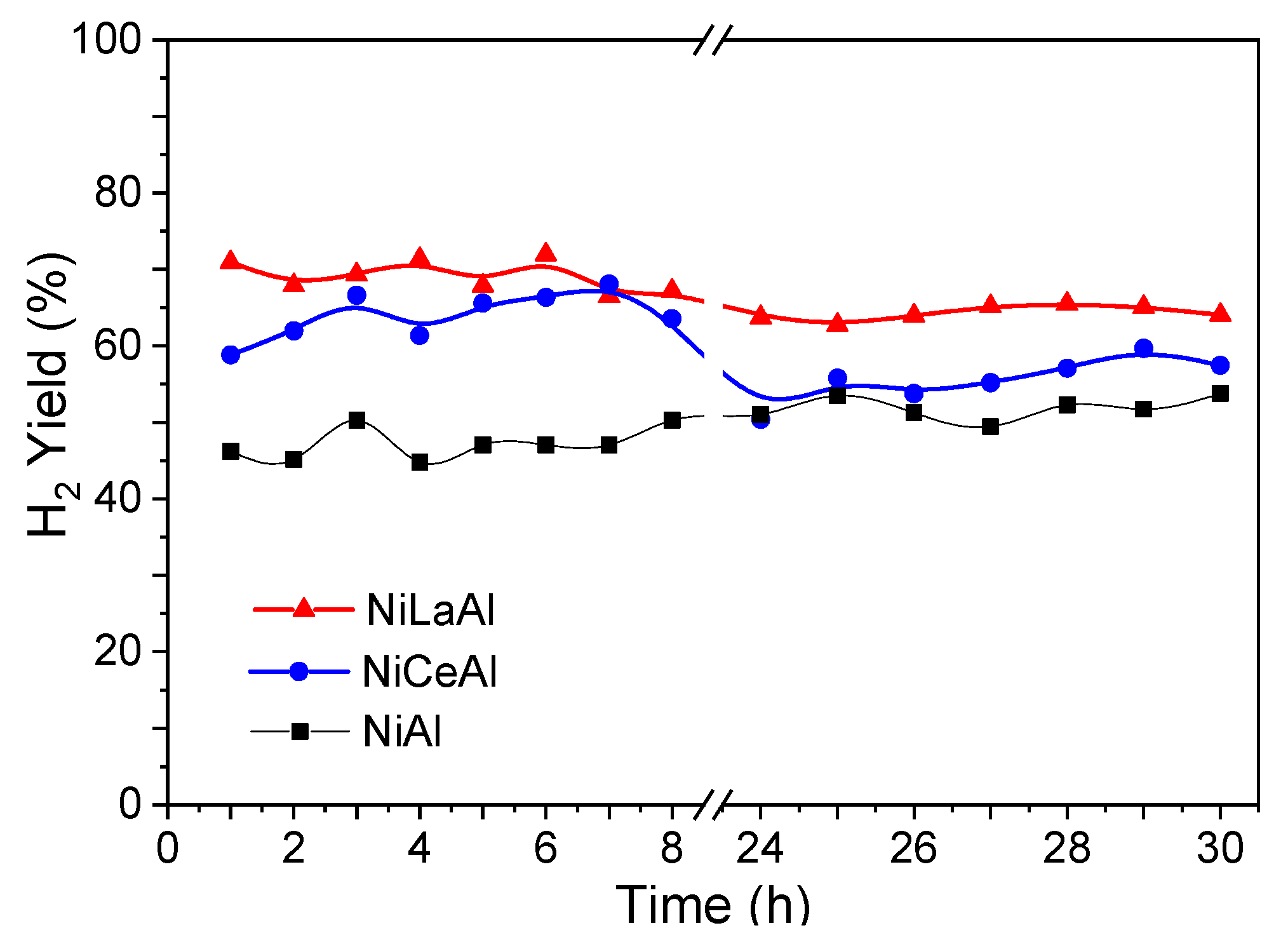
Figure 6 shows the hydrogen yield versus time on stream. Both promoters increased the average hydrogen yield, which presented the following order: NiLaAl (71.2%) > NiCeAl (63.8%) > NiAl (49.4%). These results indicate an enhancement of butanol steam reforming and shift reactions by adding basic promoters, whose basic sites promoted CO adsorption and water dissociation, leading to hydrogen formation. Wang et al. [24] studied the effect of different supports on water-gas shift reaction over Pt–Ni bimetallic catalysts. They reported a higher activity for ceria support than alumina due to the ability of ceria to promote water dissociation to form labile OH/O/H species, surface oxygen vacancies, and defect sites.
Ashok et al. [11] suggested that the surface properties of supports as availability of surface hydroxyl groups and ability to disperse the active metals are crucial for water gas-shift reaction. In this work, lanthana promoter matched both requirements, while ceria could not efficiently disperse the nickel phase. Thus, the NiLaAl catalyst provided the highest hydrogen yield. In contrast, NiCeAl presented a drop in hydrogen mean yield from 68 to 59%, comparing the first 8 h with the last 7 h of reaction.
Bizkarra et al. [7] evaluated the addition of 10 wt.% CeO2 and 6 wt.% La2O3 on 13 wt.% Ni/Al2O3 for butanol steam reforming at 600 °C, atmospheric pressure, and steam to carbon ratio of 5. They performed the reaction for 4 h and reported butanol conversion of 100% for all the catalysts, higher than the values reported in this work due to the higher temperature employed. Furthermore, they reported that ceria addition improved hydrogen yield from 58 to 65%, while lanthana addition decreased this parameter to 46%. Compared with the first 4 h of reaction, we also obtained a similar increase from 47 to 66% by ceria addition. On the other hand, NiLaAl presented a higher mean hydrogen yield (74%) in this work. This difference may be attributed to the higher lanthana content used since basic sites favor the activity for butanol reaction. Moreover, the lower temperature and higher steam to carbon ratio (11.4) employed in our work increase the shift reaction activity [11], leading to a higher hydrogen production.
Figure 7 displays CO and CO2 yields versus time on stream. It was observed that all the catalysts presented low CO yield, with values lower than 6% during all reaction time. NiLaAl presented the highest CO2 and hydrogen yields, which corroborates its great activity for shift reaction. NiCeAl showed a high CO2 yield at the beginning of the reaction. However, its reduction throughout the reaction indicates a loss in shift reaction activity, which agrees with the decrease in hydrogen yield. Furthermore, the increase in coke formation throughout time on stream by CO and CO2 hydrogenation, presented in Equations (10) and (11), could explain this behavior. Bizkarra et al. [7] also reported deactivation for a 13 wt.% Ni/10% CeO2–Al2O3 catalyst in butanol steam reforming. They reported a decrease in carbon dioxide and hydrogen yield due to carbon formation.
The NiAl catalyst presented the lowest CO and CO2 yield during all reaction time, associated with the consumption of these oxides for coke production by CO and CO2 hydrogenation, harming hydrogen production for this catalyst. On the other hand, at the beginning of the reaction, the high CO2 and low CO yields for NiCeAl and NiLaAl indicate that coke formation was mainly produced by disproportionation of CO, as presented in Equation (12). This reaction does not consume hydrogen and contributes to the higher hydrogen yield of the promoted catalysts.
CO +   H 2 C + H 2 O
CO 2 + 2 H 2 C + 2 H 2 O
2 CO C + CO 2
Methane was produced in very low amounts, as its yield was lower than 5% for all the catalysts. Thus, the catalysts were not active for methanation reactions under the reaction conditions employed in this work.
Figure 8 displays the results of thermogravimetric and differential thermal analysis of the spent catalysts. The exothermic peaks on DTA, associated with the mass loss observed by TGA, are related to the burning of coke deposits. The addition of both promoters did not significantly modify the nature of coke deposits, as the burning peak is centered approximately at the same temperature, around 580 °C. However, lanthana addition slightly shifted DTA curves to lower temperatures, indicating the presence of a more active carbon, which is easier to remove. This result also corroborates the higher stability of the lanthana-promoted catalyst. Santamaria et al. [15] also observed a shift towards lower temperatures on TPO curves of spent catalysts due to lanthana addition on the Ni/Al2O3 catalyst. They attributed this behavior to the inhibition of coke evolution due to lanthana basicity and water adsorption capacity.
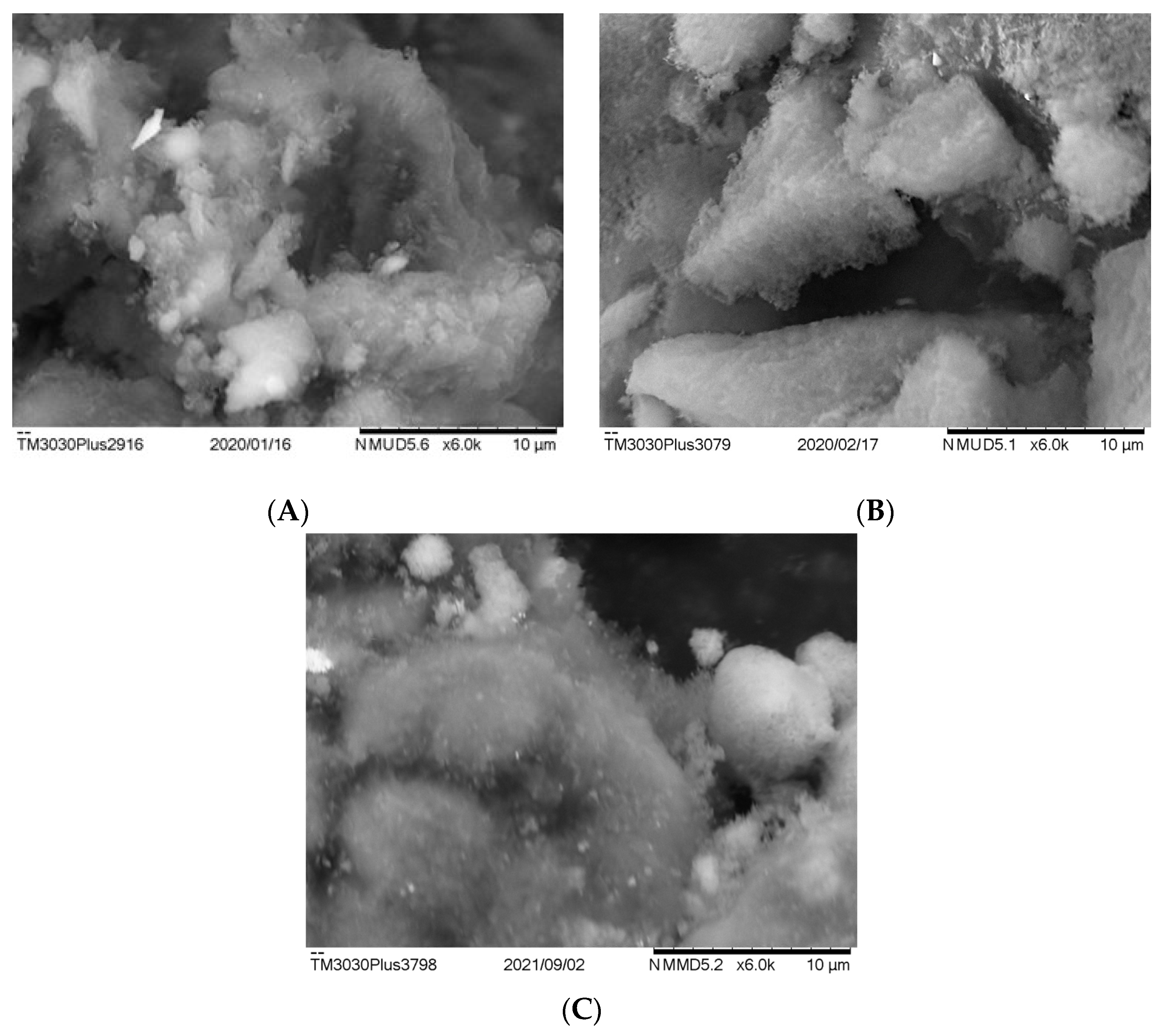
Figure 9 shows the SEM images of the spent catalysts. For all catalysts, only an irregular deposition of amorphous coke was observed, which contributes to nickel encapsulation and causes deactivation. Filamentous coke was not observed for all catalysts, agreeing with the only peak detected in TGA analysis. Santamaria et al. [15] also reported only amorphous coke on both nonpromoted and lanthana-promoted nickel/alumina catalyst after biomass–pyrolysis reforming.
Table 3 shows the coke amount on spent catalysts. NiLaAl presented the lowest coke formation, associated with its lowest acidity, as coke formation by dehydration, cracking, and polymerization reactions are favored on alumina acid sites. This result corroborates the best performance of this catalyst in terms of higher stability and nondeactivation during 30 h of reaction.
Furthermore, the addition of La2O3 could play an important role in removing carbon from the nickel surface during the reaction, as reported in the literature. Thyssen et al. [14] evaluated the addition of lanthana with different contents (10–30 wt.%) on Ni/SiO2 catalyst for glycerol steam reforming. They observed that coke formation was lower for the promoted catalyst because the formation of a La carbonate removed C species deposited on the nickel sites.
On the other hand, NiCeAl and NiAl presented a higher amount of coke on spent catalysts, explaining the deactivation observed for these catalysts. NiCeAl presented the highest coke amount (77.4%), corroborating the result reported on XRD analysis of the spent catalyst. This result indicates that, although ceria addition has also decreased catalyst acidity, the poor interaction with nickel phase promoted a higher coke formation and a less effective coke removal from the surface. Furthermore, the coke formation is enhanced by big nickel crystallite sizes, as reported in the literature [25], which agrees with this work. Silva et al. [26] and Greluk et al. [27] reported that nucleation of coke requires relatively large domains of flat terraces or large metal ensemble sizes. Thus, large ceria crystals on NiCeAl catalyst enhanced coke formation.

4. Conclusions

The addition of ceria and lanthana on Ni/alumina catalyst promoted an increase in catalytic activity and hydrogen yield, and a better stability for butanol steam reforming throughout 30 h of reaction. The NiLaAl presented the highest average hydrogen yield (71.2%) and no apparent deactivation. Moreover, the basic properties of both promoters enhanced shift reaction activity, as basic sites favor CO adsorption and water dissociation.
Lanthana was well dispersed on alumina and provided a good nickel dispersion on the support and increased nickel reducibility, which contributed to an increase in the population of metallic sites for reaction. Moreover, its coverage on alumina support contributed to titrating acid sites, lowering catalyst acidity, and weakening the acid sites. The literature reported that lanthana also reacts with coke deposits on nickel surface to form La carbonates. These properties were fundamental to decrease coke formation and avoid catalyst deactivation.
On the other hand, ceria particles agglomerated on alumina surface, and it could not efficiently disperse Ni particles. Furthermore, the decrease in catalyst acidity was not so expressive in comparison with lanthana promotion. Thus, although the literature discusses the properties of oxygen mobility in ceria supports, which could contribute to coke gasification, this was not the most relevant factor in this work. NiCeAl presented the highest coke formation, favored by the large metal ensemble sizes found in this catalyst. This explains the deactivation observed for this catalyst throughout the reaction, mainly by carbon monoxide and carbon dioxide hydrogenation routes, which compromised hydrogen formation by this catalyst.

Author Contributions

J.P.d.S.Q.M.: conceptualization, methodology, formal analysis, investigation, visualization, writing—original draft preparation; G.M.G.: formal analysis, investigation; M.A.P.d.S.: writing—review and editing, visualization, supervision; M.M.V.M.S.: conceptualization, writing—review and editing, resources, visualization, supervision, project administration, funding acquisition. All authors have read and agreed to the published version of the manuscript.

Funding

This research was funded by CNPq, FAPERJ, and CAPES.

Institutional Review Board Statement

Not applicable.

Informed Consent Statement

Not applicable.

Data Availability Statement

Not applicable.

Acknowledgments

The authors thank Greentec/EQ/UFRJ for N2 physisorption analyses.

Conflicts of Interest

The authors declare no conflict of interest. The funders had no role in the design of the study; in the collection, analyses, or interpretation of data; in the writing of the manuscript, or in the decision to publish the results.

References

  1. Roy, B.; Sullivan, H.; Leclerc, C.A. Effect of variable conditions on steam reforming and aqueous phase reforming of n-butanol over Ni/CeO2 and Ni/Al2O3 catalysts. J. Power Sources 2014, 267, 280–287. [Google Scholar] [CrossRef]
  2. Nabgan, W.; Tuan Abdullah, T.A.; Mat, R.; Nabgan, B.; Gambo, Y.; Ibrahim, M.; Ahmad, A.; Jalil, A.A.; Triwahyono, S.; Saeh, I. Renewable hydrogen production from bio-oil derivative via catalytic steam reforming: An overview. Renew. Sustain. Energy Rev. 2017, 79, 347–357. [Google Scholar] [CrossRef]
  3. Yadav, A.K.; Vaidya, P.D. Reaction Kinetics of Steam Reforming of n-Butanol over a Ni/Hydrotalcite Catalyst. Chem. Eng. Technol. 2018, 41, 890–896. [Google Scholar] [CrossRef]
  4. Oasmaa, A.; Meier, D. Norms and standards for fast pyrolysis liquids: 1. Round robin test. J. Anal. Appl. Pyrolysis 2005, 73, 323–334. [Google Scholar] [CrossRef]
  5. Nahar, G.A.; Madhani, S.S. Thermodynamics of hydrogen production by the steam reforming of butanol: Analysis of inorganic gases and light hydrocarbons. Int. J. Hydrogen Energy 2010, 35, 98–109. [Google Scholar] [CrossRef]
  6. Bimbela, F.; Chen, D.; Ruiz, J.; García, L.; Arauzo, J. Ni/Al coprecipitated catalysts modified with magnesium and copper for the catalytic steam reforming of model compounds from biomass pyrolysis liquids. Appl. Catal. B Environ. 2012, 119–120, 1–12. [Google Scholar] [CrossRef]
  7. Bizkarra, K.; Barrio, V.L.; Yartu, A.; Requies, J.; Arias, P.L.; Cambra, J.F. Hydrogen production from n-butanol over alumina and modified alumina nickel catalysts. Int. J. Hydrogen Energy 2015, 40, 5272–5280. [Google Scholar] [CrossRef]
  8. Medrano, J.A.; Oliva, M.; Ruiz, J.; García, L.; Arauzo, J. Catalytic steam reforming of butanol in a fluidized bed and comparison with other oxygenated compounds. Fuel Process. Technol. 2014, 124, 123–133. [Google Scholar] [CrossRef]
  9. Jun, K.W.; Roh, H.S.; Chary, K.V.R. Structure and catalytic properties of ceria-based nickel catalysts for CO2 reforming of methane. Catal. Surv. Asia 2007, 11, 97–113. [Google Scholar] [CrossRef]
  10. Silva, J.M.; Soria, M.A.; Madeira, L.M. Challenges and strategies for optimization of glycerol steam reforming process. Renew. Sustain. Energy Rev. 2015, 42, 1187–1213. [Google Scholar] [CrossRef] [Green Version]
  11. Ashok, J.; Wai, M.H.; Kawi, S. Nickel-based Catalysts for High-temperature Water Gas Shift Reaction-Methane Suppression. ChemCatChem 2018, 10, 3927–3942. [Google Scholar] [CrossRef]
  12. Iriondo, A.; Barrio, V.L.; Cambra, J.F.; Arias, P.L.; Guemez, M.B.; Sanchez-Sanchez, M.C.; Navarro, R.M.; Fierro, J.L.G. Glycerol steam reforming over Ni catalysts supported on ceria and ceria-promoted alumina. Int. J. Hydrogen Energy 2010, 35, 11622–11633. [Google Scholar] [CrossRef]
  13. Tsipouriari, V.A.; Verykios, X.E. Kinetic study of the catalytic reforming of methane with carbon dioxide to synthesis gas over Ni/La2O3 catalyst. Catal. Today 2001, 64, 83–90. [Google Scholar] [CrossRef]
  14. Thyssen, V.V.; Maia, T.A.; Assaf, E.M. Ni supported on La2O3-SiO2 used to catalyze glycerol steam reforming. Fuel 2013, 105, 358–363. [Google Scholar] [CrossRef]
  15. Santamaria, L.; Arregi, A.; Lopez, G.; Artetxe, M.; Amutio, M.; Bilbao, J.; Olazar, M. Effect of La2O3 promotion on a Ni/Al2O3 catalyst for H2 production in the in-line biomass pyrolysis-reforming. Fuel 2020, 262, 116593. [Google Scholar] [CrossRef]
  16. Patel, R.; Patel, S. Renewable hydrogen production from butanol: A review. Clean Energy 2017, 1, 90–101. [Google Scholar] [CrossRef]
  17. Anderson, J.R. Structure of Metallic Catalysts; Academic Press: London, UK, 1975. [Google Scholar]
  18. Mortola, V.B.; Damyanova, S.; Zanchet, D.; Bueno, J.M.C. Surface and structural features of Pt/CeO2-La2O3-Al2O3 catalysts for partial oxidation and steam reforming of methane. Appl. Catal. B Environ. 2011, 107, 221–236. [Google Scholar] [CrossRef]
  19. Mazumder, J.; De Lasa, H.I. Ni catalysts for steam gasification of biomass: Effect of La2O3 loading. Catal. Today 2014, 237, 100–110. [Google Scholar] [CrossRef]
  20. Dan, M.; Mihet, M.; Tasnadi-Asztalos, Z.; Imre-Lucaci, A.; Katona, G.; Lazar, M.D. Hydrogen production by ethanol steam reforming on nickel catalysts: Effect of support modification by CeO2 and La2O3. Fuel 2015, 147, 260–268. [Google Scholar] [CrossRef]
  21. Rynkowski, J.M.; Paryjczak, T.; Lenik, M. On the nature of oxidic nickel phases in NiO/γ-Al2O3 catalysts. Appl. Catal. A Gen. 1993, 106, 73–82. [Google Scholar] [CrossRef]
  22. Ribeiro, N.F.P.; Henriques, C.A.; Schmal, M. Copper-based catalysts for synthesis of methylamines: The effect of the metal and the role of the support. Catal. Lett. 2005, 104, 111–119. [Google Scholar] [CrossRef]
  23. Montini, T.; Singh, R.; Das, P.; Lorenzut, B.; Bertero, N.; Riello, P.; Benedetti, A.; Giambastiani, G.; Bianchini, C.; Zinoviev, S.; et al. Renewable H2 from glycerol steam reforming: Effect of La2O3 and CeO2 addition to Pt/Al2O3 catalysts. ChemSusChem 2010, 3, 619–628. [Google Scholar] [CrossRef] [PubMed]
  24. Wang, T.; Porosoff, M.D.; Chen, J.G. Effects of oxide supports on the water-gas shift reaction over PtNi bimetallic catalysts: Activity and methanation inhibition. Catal. Today 2014, 233, 61–69. [Google Scholar] [CrossRef]
  25. Lisboa, J.D.S.; Santos, D.C.R.M.; Passos, F.B.; Noronha, F.B. Influence of the addition of promoters to steam reforming catalysts. Catal. Today 2005, 101, 15–21. [Google Scholar] [CrossRef]
  26. Da Silva, A.L.M.; Den Breejen, J.P.; Mattos, L.V.; Bitter, J.H.; De Jong, K.P.; Noronha, F.B. Cobalt particle size effects on catalytic performance for ethanol steam reforming—Smaller is better. J. Catal. 2014, 318, 67–74. [Google Scholar] [CrossRef]
  27. Greluk, M.; Rotko, M.; Turczyniak-Surdacka, S. Enhanced catalytic performance of La2O3 promoted Co/CeO2 and Ni/CeO2 catalysts for effective hydrogen production by ethanol steam reforming. Renew. Energy 2020, 155, 378–395. [Google Scholar] [CrossRef]
Figure 1. Pore size distribution for supports (A) and catalysts (B) determined by N2 physisorption.
Processes 09 01815 g001
Figure 2. XRD patterns in different stages (support, calcined, reduced, and spent catalysts) of NiAl (A), NiCeAl (B), and NiLaAl (C).
Processes 09 01815 g002
Figure 3. TPR profiles of calcined catalysts.
Processes 09 01815 g003
Figure 4. TPD-NH3 profiles of reduced catalysts.
Processes 09 01815 g004
Figure 5. Butanol global conversion (A) and conversion to gas (B) versus time on stream.
Processes 09 01815 g005
Figure 6. Hydrogen yield versus time on stream.
Processes 09 01815 g006
Figure 7. Carbon monoxide and carbon dioxide yields versus time on stream.
Processes 09 01815 g007
Figure 8. TGA and DTA profiles of NiAl (A), NiCeAl (B), and (C) NiLaAl after 30 h of butanol steam reforming reaction at 500 °C.
Processes 09 01815 g008aProcesses 09 01815 g008b
Figure 9. Micrographs of spent catalysts: NiAl (A), NiCeAl (B), and NiLaAl (C) with magnification of 6000×.
Processes 09 01815 g009
Table 1. Chemical composition of catalysts, BET surface area, pore volume, and mean pore size of supports and calcined catalysts.
Catalyst/
Support
NiO
(wt.%)
CeO2
(wt.%)
La2O3
(wt.%)
SBET
(m² g−1)
Vpore
(cm³ g−1)
Pore Size
(Å)
Al0002010.3781.7
NiAl21001460.3465.4
CeAl01001030.26177.4
NiCeAl2070630.23191.7
LaAl00988.50.25186.0
NiLaAl1906530.55360.9
Table 2. Nickel crystallite size, nickel dispersion, coke crystallite size, reduction degree of NiO (RD), and amount of desorbed NH3 per mass and per BET specific area.
CatalystNi
Crystallite Size
(nm)
Ni
Dispersion
(%)
Coke
Crystallite Size (nm)
RD (%)μmol NH3 gcat¹μmol NH3 m−2
NiAl7.9 ± 1.312.03.6 ± 1.2 90458.93.1
NiCeAl9.1 ± 0.911.13.1 ± 1.2 97120.31.9
NiLaAl6.9 ± 0.914.62.6 ± 0.610026.40.5
Table 3. Coke formation on spent catalysts measured by TGA analysis.
CatalystCoke (wt.%)
NiAl63.5
NiCeAl77.4
NiLaAl56.2
Publisher’s Note: MDPI stays neutral with regard to jurisdictional claims in published maps and institutional affiliations.

