
Influence of Porous Media Aperture Arrangement on CH4/Air Combustion Characteristics in Micro Combustor


Abstract
1. Introduction
2. Numerical Model
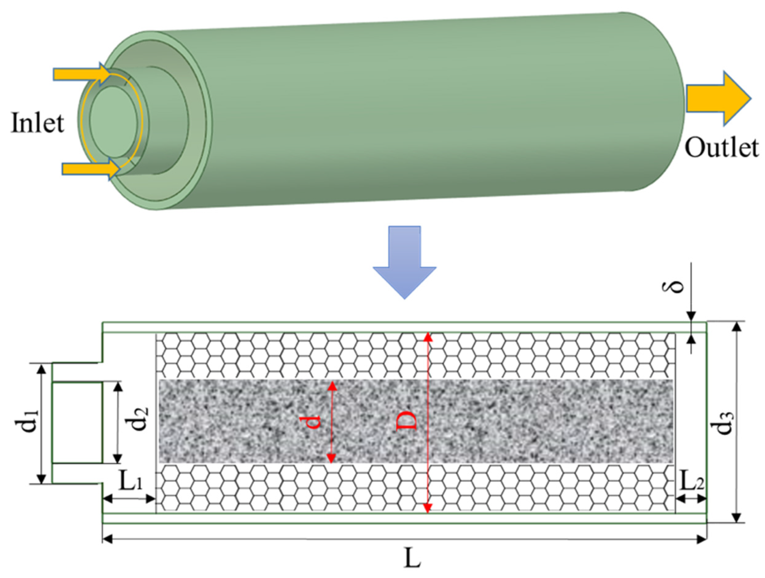
2.1. Physical Model
2.2. Mathematical Model
2.3. Boundary Conditions
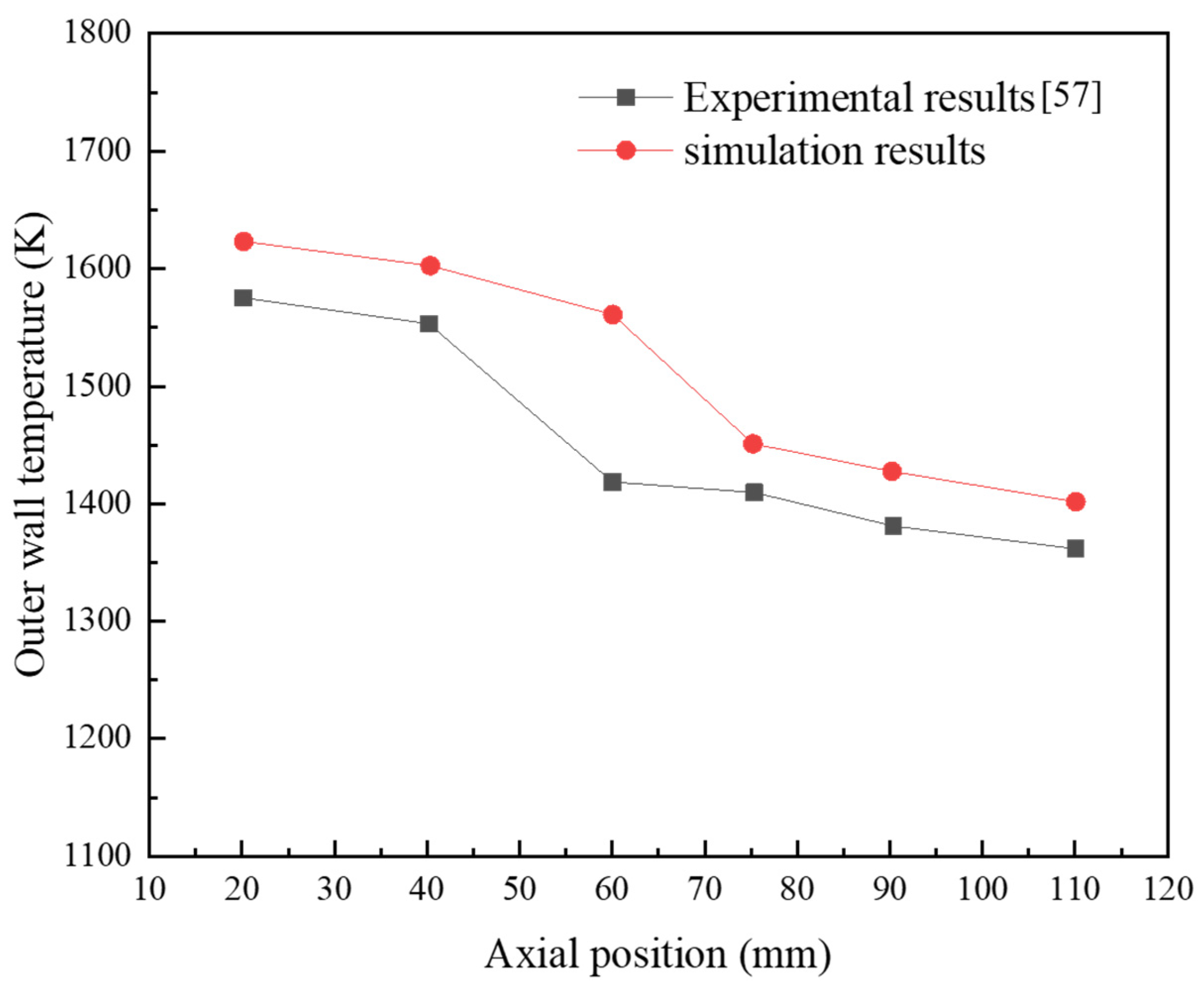
2.4. Numerical Simulation Verification
3. Results and Discussion
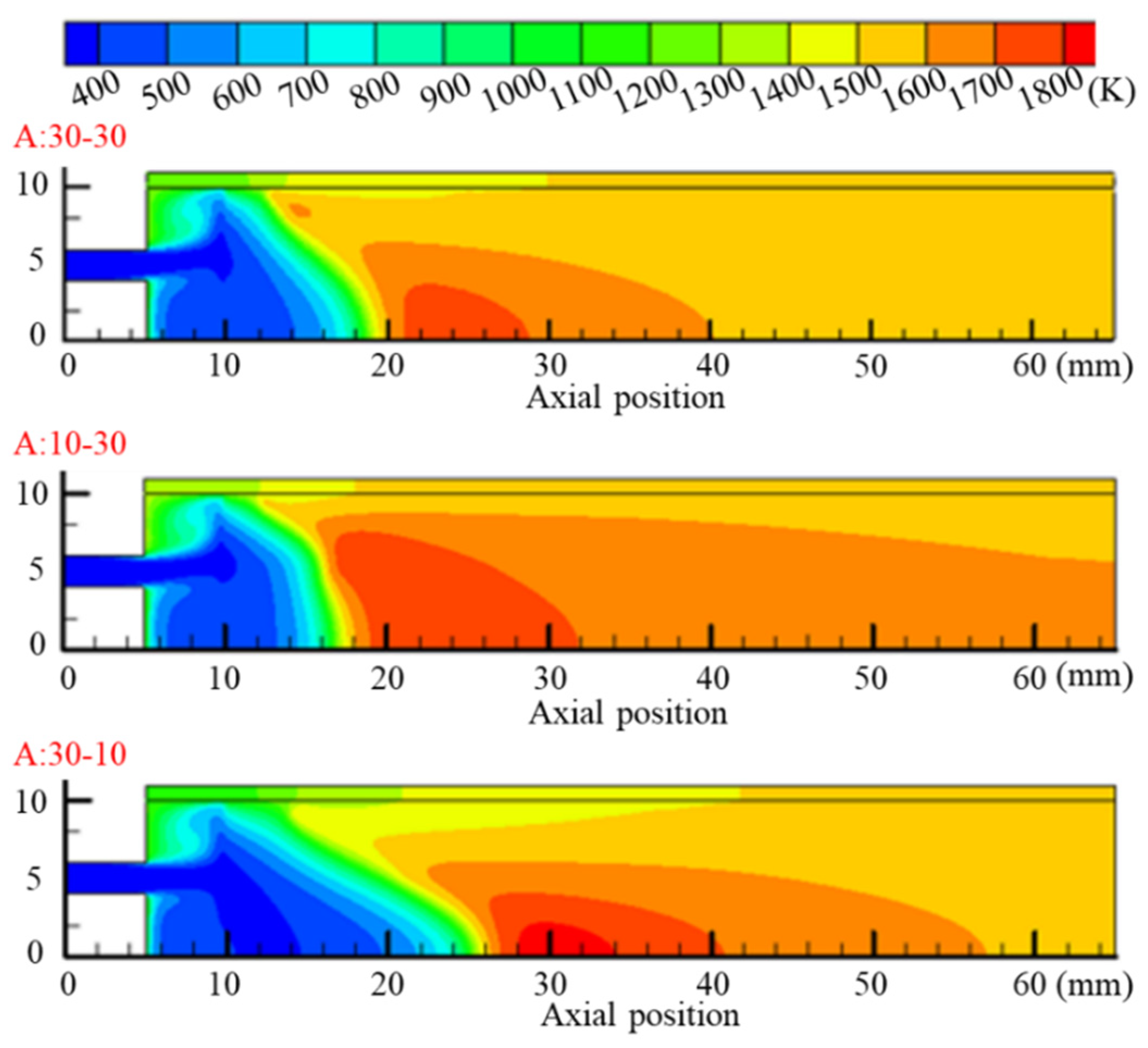
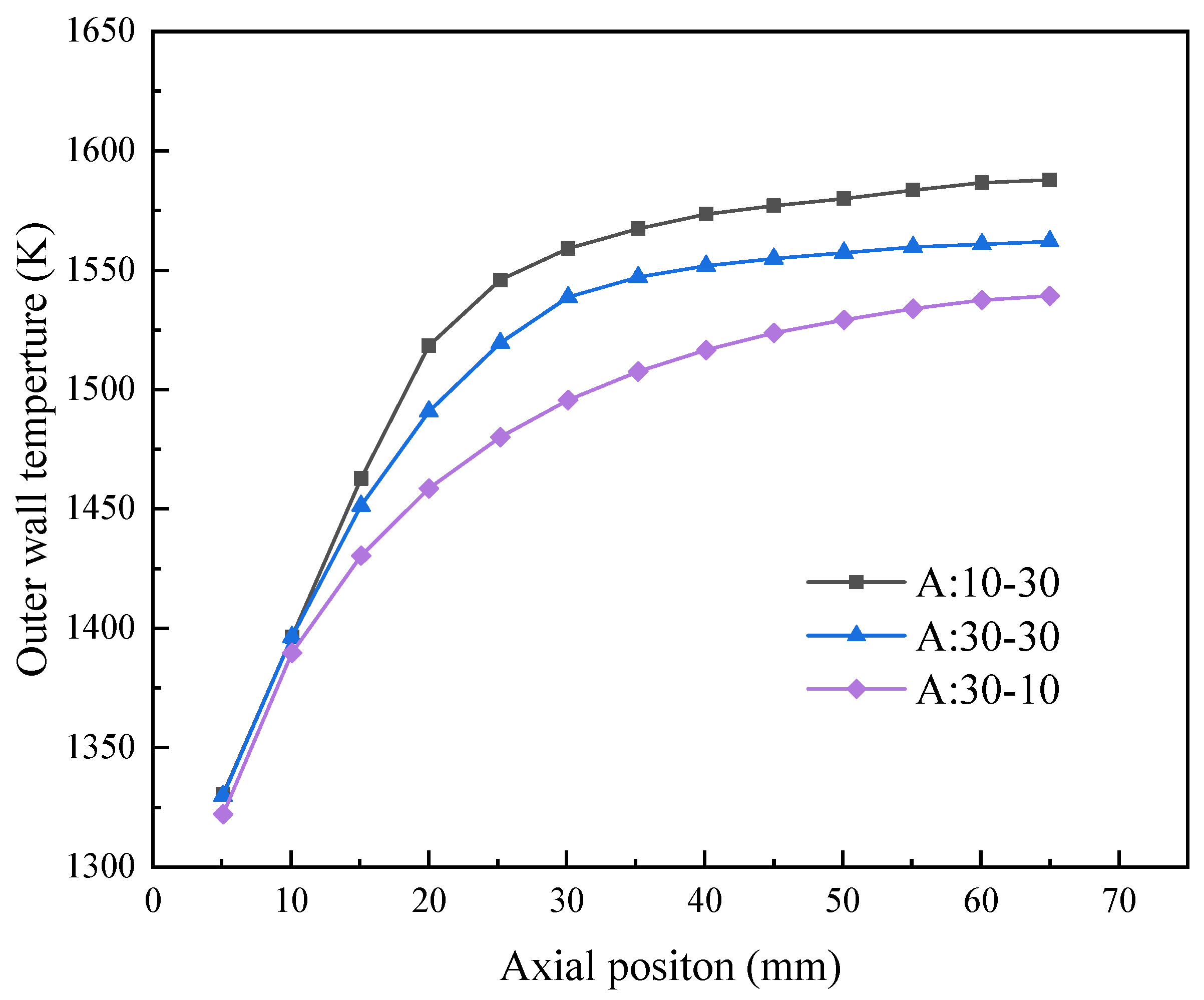
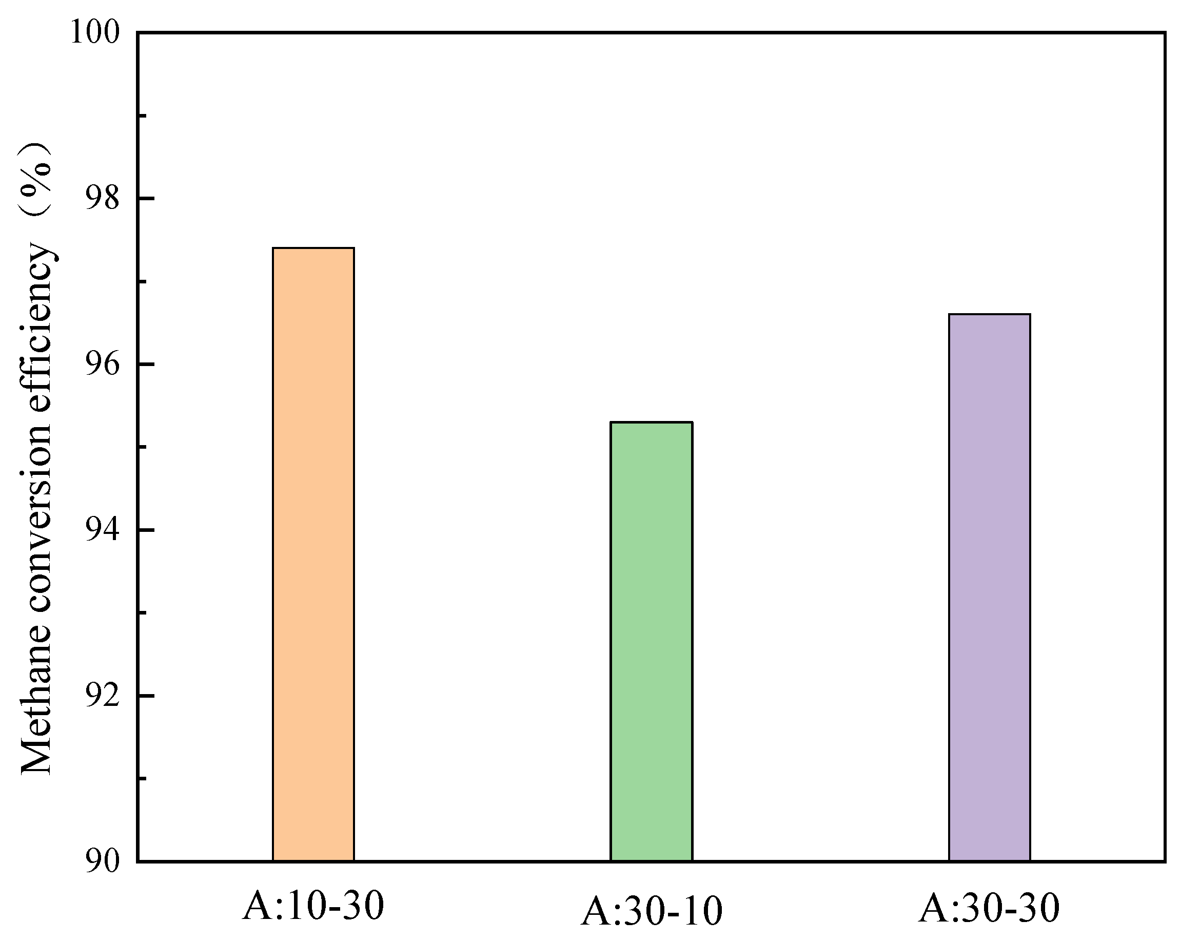
3.1. Effect of PM Layout
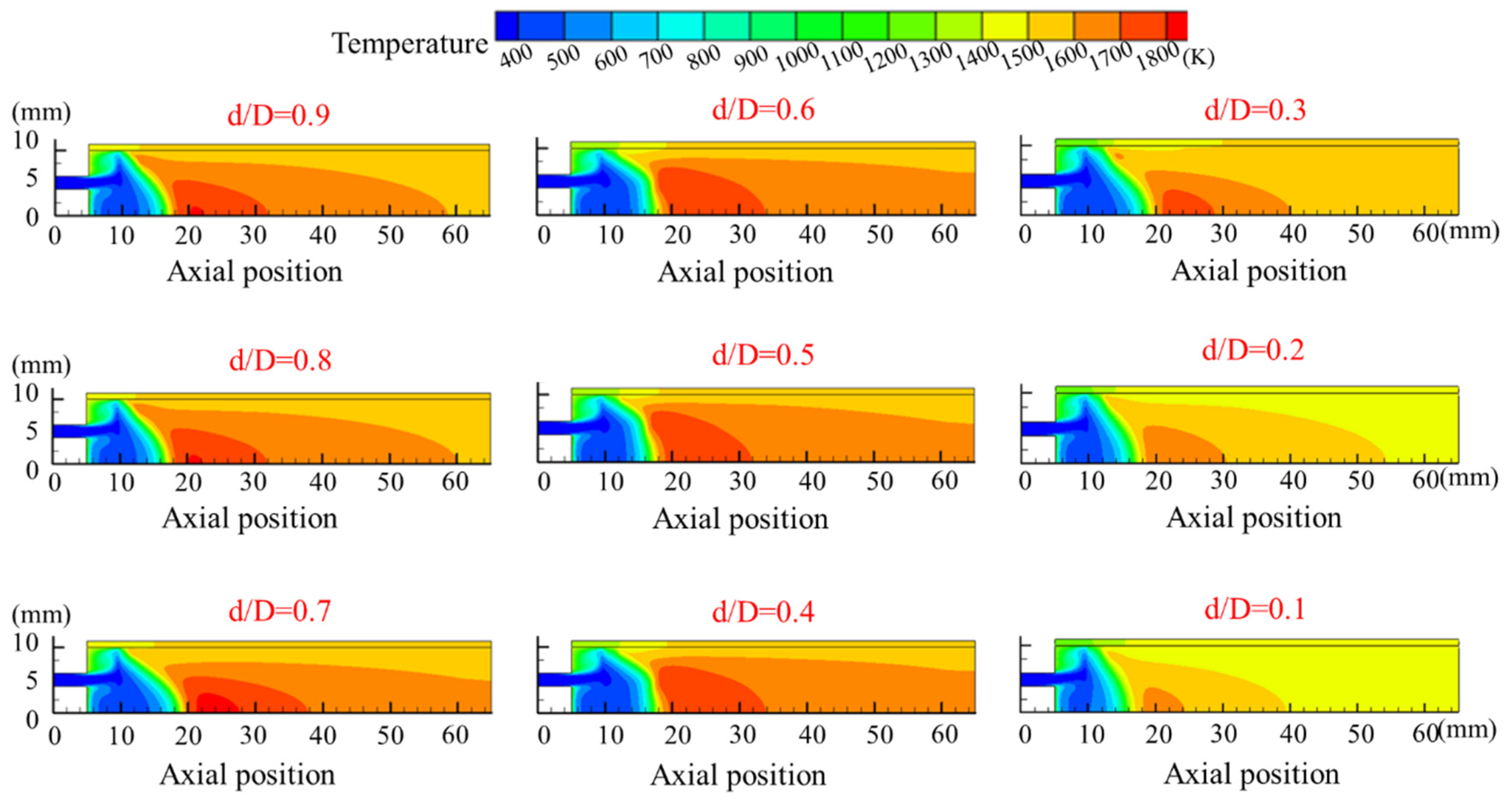
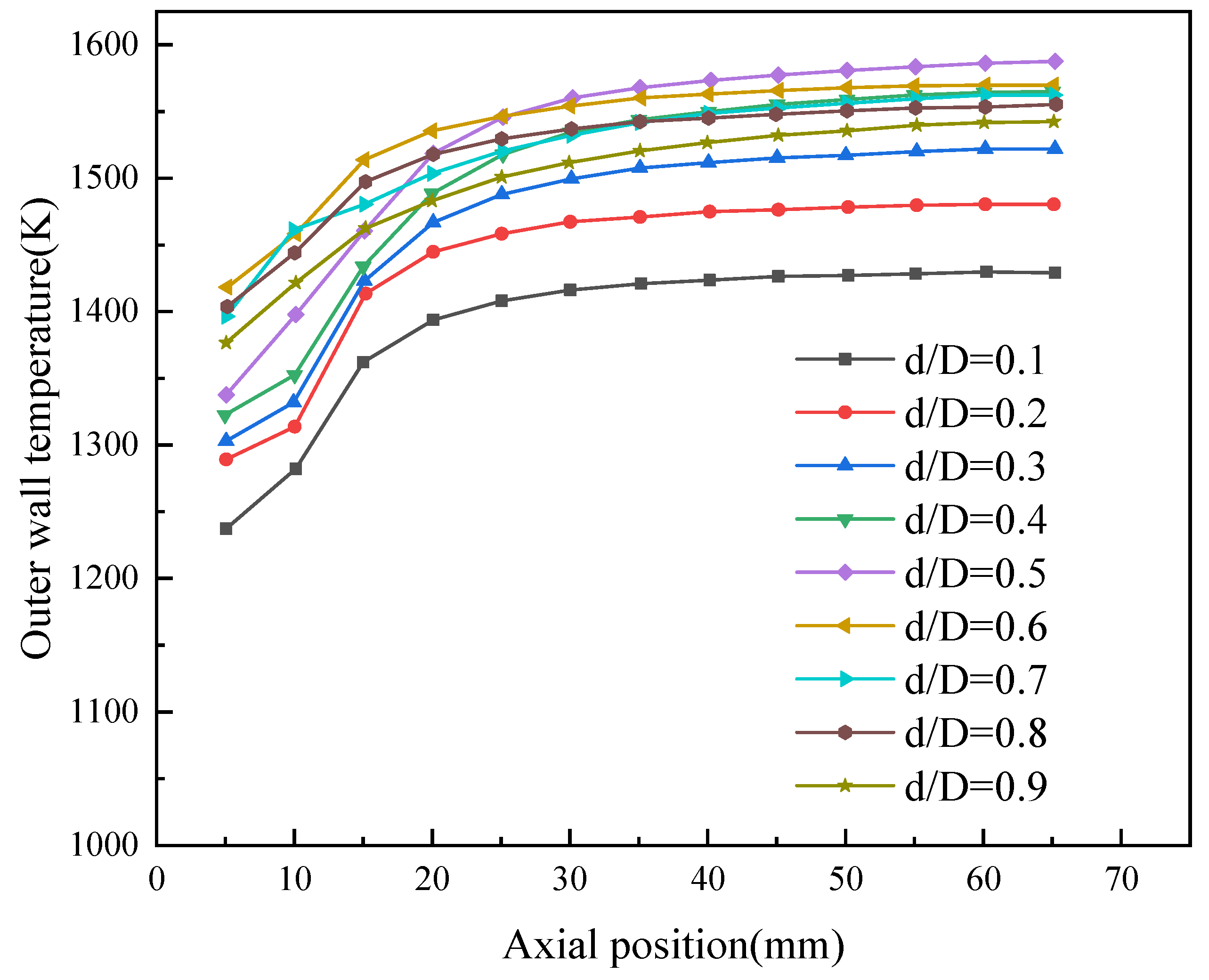
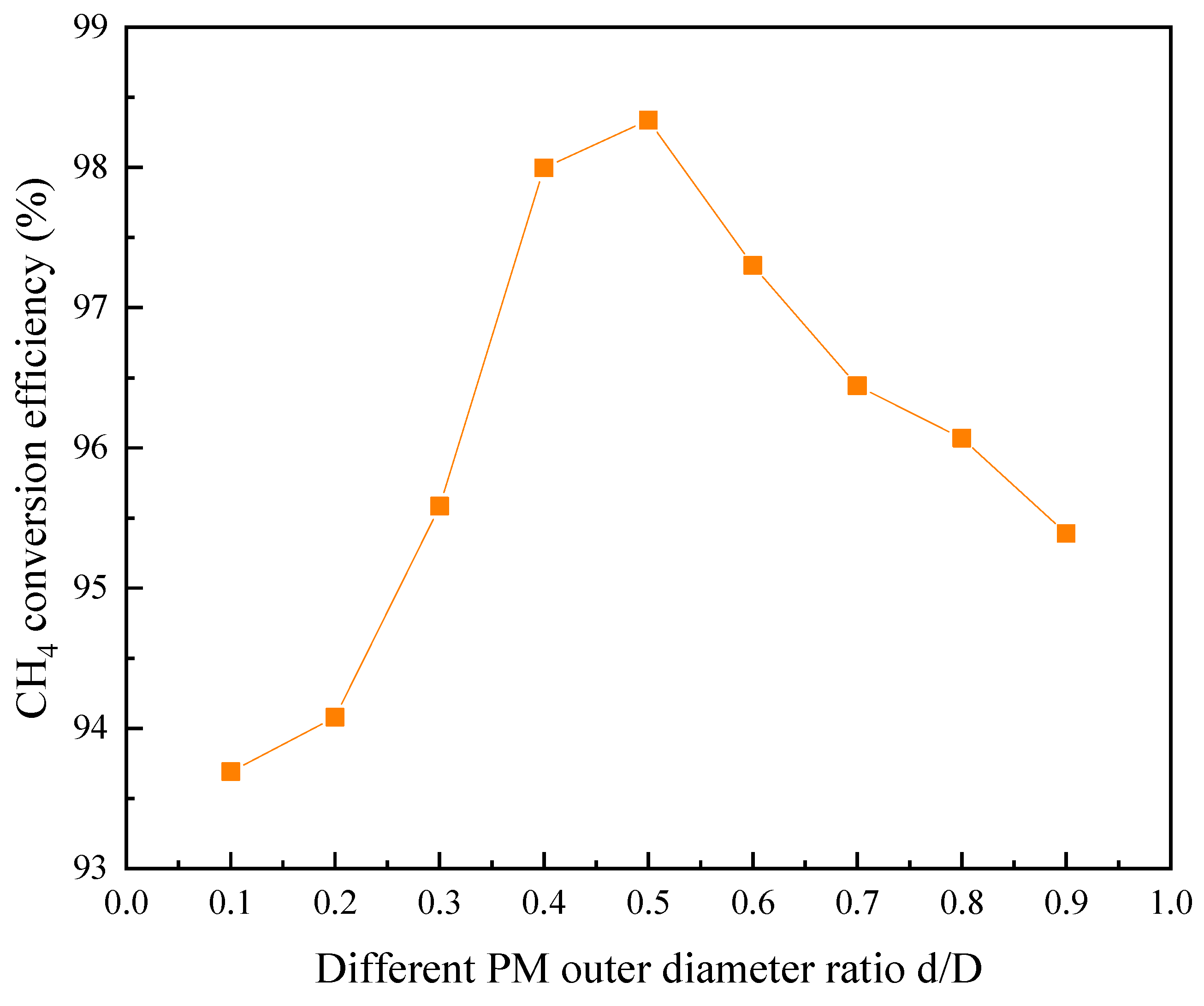
3.2. Effect of d/D in Porous Media
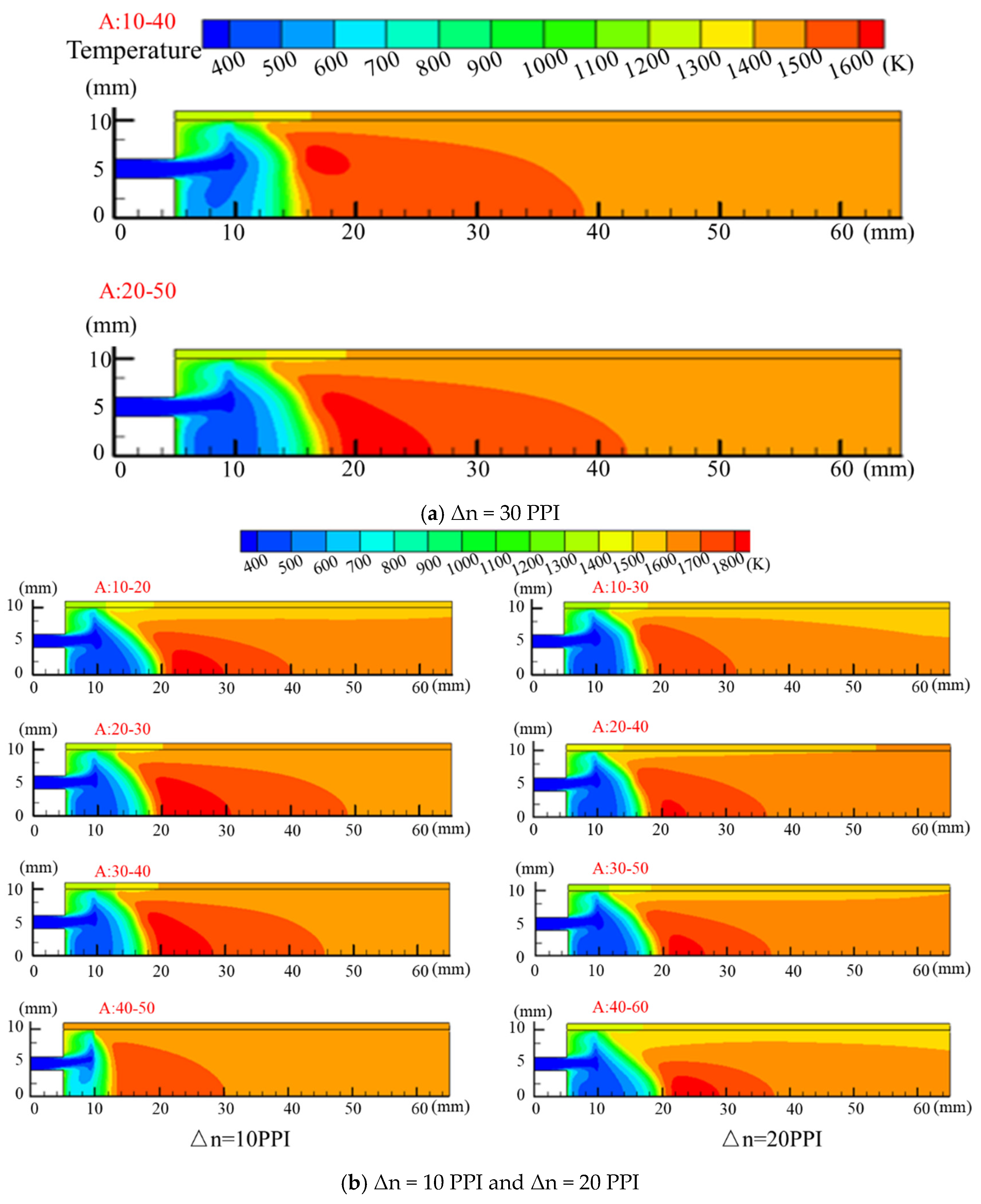
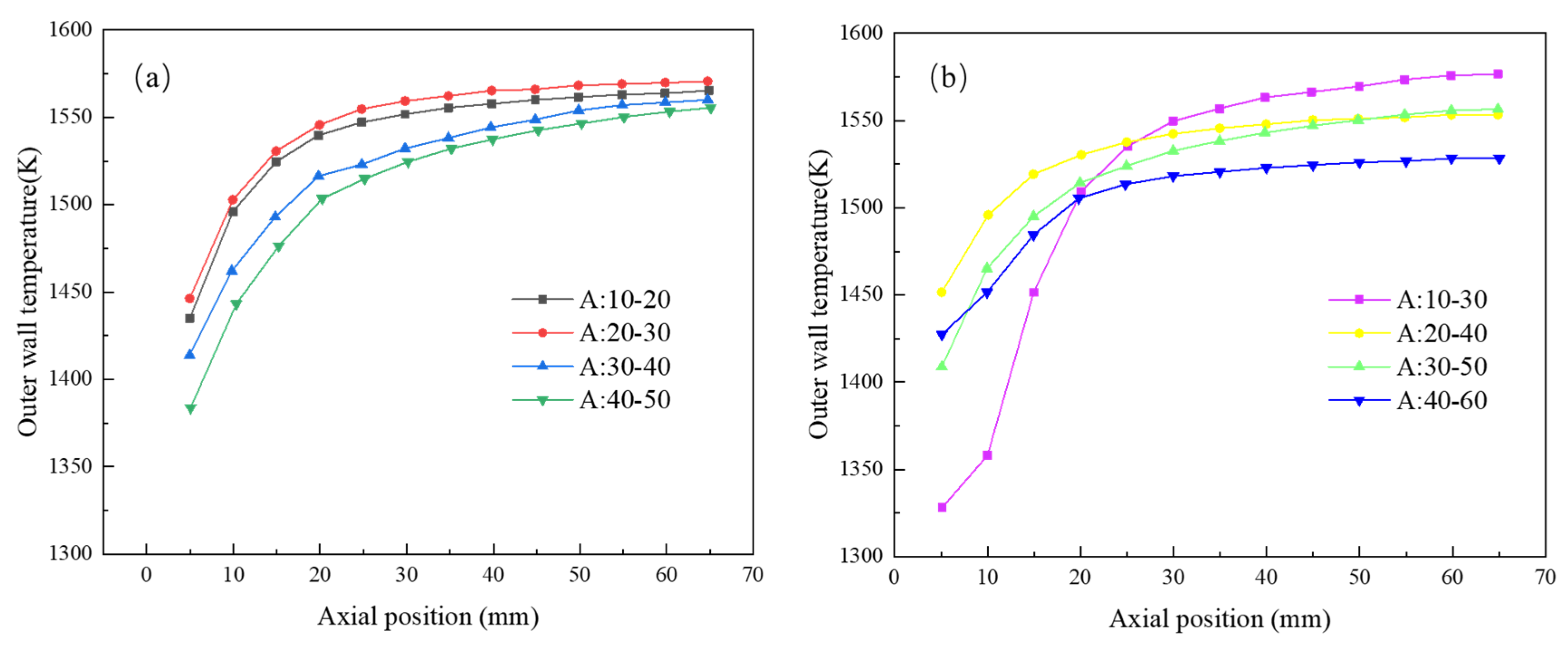
3.3. Effect of Porosity Gradient
3.4. Lean Flammable Limit
4. Conclusions
Author Contributions
Funding
Conflicts of Interest
References
- E, J.; Ding, J.; Chen, J.; Liao, G.; Zhang, F.; Luo, B. Process in micro-combustion and energy conversion of micro power system: A review. Energy Convers. Manag. 2021, 246, 114664. [Google Scholar] [CrossRef]
- Gharehghani, A.; Ghasemi, K.; Siavashi, M.; Mehranfar, S. Applications of porous materials in combustion systems: A comprehensive and state-of-the-art review. Fuel 2021, 304, 121411. [Google Scholar] [CrossRef]
- Erdiwansyah, E.; Mahidin, M.; Husin, H.; Nasaruddin, N.; Muhtadin, M.; Faisal, M.; Gani, A.; Usman, U.; Mamat, R. Combustion Efficiency in a Fluidized-Bed Combustor with a Modified Perforated Plate for Air Distribution. Processes 2021, 9, 1489. [Google Scholar] [CrossRef]
- He, Z.; Yan, Y.; Zhang, Z. Thermal management and temperature uniformity enhancement of electronic devices by micro heat sinks: A review. Energy 2020, 216, 119223. [Google Scholar] [CrossRef]
- Xu, F.; Yan, Y.; He, Z.; Yang, Z.; Zhang, L. Numerical study on the influence of controllable flow ratio on combustion characteristics of a controllable central slotted bluff body and cavity combined micro combustor. Int. J. Hydrogen Energy 2021, 46, 6901–6914. [Google Scholar] [CrossRef]
- He, Z.; Yan, Y.; Feng, S.; Li, X.; Fang, R.; Ou, Z.; Yang, Z. Numerical investigation on a multi-channel micro combustor fueled with hydrogen for a micro-thermophotovoltaic system. Int. J. Hydrogen Energy 2021, 46, 4460–4471. [Google Scholar] [CrossRef]
- Wang, Y.; Zhang, M.; Chang, S.; Li, S.; Huang, X. Laser-Induced Ignition and Combustion Behavior of Individual Graphite Microparticles in a Micro-Combustor. Processes 2020, 8, 1493. [Google Scholar] [CrossRef]
- Zhao, T.; Yan, Y.; He, Z.; Gao, W.; Yang, Z. Influence of hole size and number on pressure drop and energy output of the micro-cylindrical combustor inserting with an internal spiral fin with holes. Int. J. Hydrogen Energy 2021, 46, 26594–26606. [Google Scholar] [CrossRef]
- Zhao, T.; Yan, Y.; He, Z.; Yang, Z. Influence of multi-structure optimization on the comprehensive performance of micro-cylindrical combustor inserting with spiral fin by using grey relational analysis and analysis of variance. Int. J. Hydrogen Energy 2021, 46, 28327–28337. [Google Scholar] [CrossRef]
- Zhao, Z.; Wang, W.; Zuo, Z.; Kuang, N. Investigation on the flame characteristics of premixed propane/air in a micro opposed flow porous combustor. Energy 2022, 238, 121721. [Google Scholar] [CrossRef]
- Li, Q.; Zuo, W.; Zhang, Y.; Li, J.; He, Z. Effects of rectangular rib on exergy efficiency of a hydrogen-fueled micro combustor. Int. J. Hydrogen Energy 2020, 45, 10155–10163. [Google Scholar] [CrossRef]
- Benim, A.C.; Iqbal, S.; Meier, W.; Joos, F.; Wiedermann, A. Numerical investigation of turbulent swirling flames with validation in a gas turbine model combustor. Appl. Therm. Eng. 2017, 110, 202–212. [Google Scholar] [CrossRef]
- Li, L.; Yang, G.; Fan, A. Non-premixed combustion characteristics and thermal performance of a catalytic combustor for micro-thermophotovoltaic systems. Energy 2021, 214, 118893. [Google Scholar] [CrossRef]
- Yan, Y.; Wu, G.; Huang, W.; Zhang, L.; Li, L.; Yang, Z. Numerical comparison study of methane catalytic combustion characteristic between newly proposed opposed counter-flow micro-combustor and the conventional ones. Energy 2019, 170, 403–410. [Google Scholar] [CrossRef]
- Pan, J.; Miao, N.; Lu, Z.; Lu, Q.; Yang, W.; Pan, Z.; Zhang, Y. Experimental and numerical study on the transition conditions and influencing factors of hetero-/homogeneous reaction for H2/Air mixture in micro catalytic combustor. Appl. Therm. Eng. 2019, 154, 120–130. [Google Scholar] [CrossRef]
- Landi, G.; Di Benedetto, A.; Barbato, P.S.; Russo, G.; Di Sarli, V. Transient behavior of structured LaMnO3 catalyst during methane combustion at high pressure. Chem. Eng. Sci. 2014, 116, 350–358. [Google Scholar] [CrossRef]
- Chen, J.; Yan, L.; Song, W.; Xu, D. Effect of heat and mass transfer on the combustion stability in catalytic micro-combustors. Appl. Therm. Eng. 2018, 131, 750–765. [Google Scholar] [CrossRef]
- Di Benedetto, A.; Di Sarli, V.; Russo, G. A novel catalytic-homogenous micro-combustor. Catal. Today 2009, 147, S156–S161. [Google Scholar] [CrossRef]
- Chen, J.; Song, W.; Gao, X.; Xu, D. Hetero-/homogeneous combustion and flame stability of fuel-lean propane–air mixtures over platinum in catalytic micro-combustors. Appl. Therm. Eng. 2016, 100, 932–943. [Google Scholar] [CrossRef]
- Zhang, Y.; Pan, J.; Tang, A.; Liu, Y.; Pan, Z.; Lu, Q.; Otchere, P. Effect of gas-phase reaction on catalytic reaction for H2/O2 mixture in micro combustor. Int. J. Hydrogen Energy 2017, 42, 16855–16865. [Google Scholar] [CrossRef]
- Chen, J.; Song, W.; Xu, D. Optimal combustor dimensions for the catalytic combustion of methane-air mixtures in micro-channels. Energy Convers. Manag. 2017, 134, 197–207. [Google Scholar] [CrossRef]
- Jin, J.; Kwon, S. Fabrication and performance test of catalytic micro-combustors as a heat source of methanol steam reformer. Int. J. Hydrogen Energy 2010, 35, 1803–1811. [Google Scholar] [CrossRef]
- Ipsakis, D.; Damartzis, T.; Papadopoulou, S.; Voutetakis, S. Dynamic Modeling and Control of a Coupled Reforming/Combustor System for the Production of H2 via Hydrocarbon-Based Fuels. Processes 2020, 8, 1243. [Google Scholar] [CrossRef]
- Zuo, W.; Zhang, Y.; Li, Q.; Li, J.; He, Z. Numerical investigations on hydrogen-fueled micro-cylindrical combustors with cavity for micro-thermophotovoltaic applications. Energy 2021, 223, 120098. [Google Scholar] [CrossRef]
- Gao, W.; Yan, Y.; Huang, L.; Shen, K.; He, Z.; Gao, B. Numerical comparison of premixed H2/air combustion characteristic of three types of micro cavity-combustors with guide vanes, bluff body, guide vanes and bluff body respectively. Int. J. Hydrogen Energy 2021, 46, 24382–24394. [Google Scholar] [CrossRef]
- Su, Y.; Song, J.; Chai, J.; Cheng, Q.; Luo, Z.; Lou, C.; Fu, P. Numerical investigation of a novel micro combustor with double-cavity for micro-thermophotovoltaic system. Energy Convers. Manag. 2015, 106, 173–180. [Google Scholar] [CrossRef]
- Yang, W.; Fan, A.; Yao, H. Effect of inlet temperature on combustion efficiency of lean H2/air mixtures in a micro-combustor with wall cavities. Appl. Therm. Eng. 2016, 107, 837–843. [Google Scholar] [CrossRef]
- He, Z.; Yan, Y.; Fang, R.; Ou, Z.; Zhang, Z.; Yang, Z.; Zhang, Z. Numerical investigation of a novel micro combustor with a central and bilateral slotted blunt body. Int. J. Hydrogen Energy 2021, 46, 23564–23579. [Google Scholar] [CrossRef]
- Li, L.; Fan, A. A numerical study on non-premixed H2/air flame stability in a micro-combustor with a slotted bluff-body. Int. J. Hydrogen Energy 2021, 46, 2658–2666. [Google Scholar] [CrossRef]
- He, Z.; Yan, Y.; Xu, F.; Yang, Z.; Cui, H.; Wu, Z.; Li, L. Combustion characteristics and thermal enhancement of premixed hydrogen/air in micro combustor with pin fin arrays. Int. J. Hydrogen Energy 2020, 45, 5014–5027. [Google Scholar] [CrossRef]
- Chakravarthy, S.; Randive, P. LES study on the effect of cavity configuration on combustion characteristics of a scramjet combustor with air-throttling. Int. J. Hydrogen Energy 2021, 46, 22534–22553. [Google Scholar] [CrossRef]
- Suneetha, L.; Randive, P.; Pandey, K.M. Numerical investigation on implication of dual cavity on combustion characteristics in strut based scramjet combustor. Int. J. Hydrogen Energy 2019, 44, 32080–32094. [Google Scholar] [CrossRef]
- Bao, H.; Zhou, J.; Pan, Y. Effect of cavity configuration on kerosene spark ignition in a scramjet combustor at Ma 4.5 flight condition. Acta Astronaut. 2015, 117, 368–375. [Google Scholar] [CrossRef]
- Yang, H.-C.; Park, H.-O.; Park, K.-T.; Kim, S.-J.; Kim, H.-J.; Eun, H.-C.; Lee, K. Development of Carbonization and a Relatively High-Temperature Halogenation Process for the Removal of Radionuclides from Spent Ion Exchange Resins. Processes 2021, 9, 96. [Google Scholar] [CrossRef]
- He, Z.; Yan, Y.; Feng, S.; Li, X.; Yang, Z.; Ran, J.; Gan, Y. Investigation on premixed methane/air combustion characteristics in heat recirculation micro combustor with separating cylinder. Chem. Eng. Process. 2020, 153, 107987. [Google Scholar] [CrossRef]
- Tang, A.; Cai, T.; Huang, Q.; Deng, J.; Pan, J. Numerical study on energy conversion performance of micro-thermophotovoltaic system adopting a heat recirculation micro-combustor. Fuel Process. Technol. 2018, 180, 23–31. [Google Scholar] [CrossRef]
- Tang, A.; Cai, T.; Deng, J.; Xu, Y.; Pan, J. Experimental investigation on combustion characteristics of premixed propane/air in a micro-planar heat recirculation combustor. Energy Convers. Manag. 2017, 152, 65–71. [Google Scholar] [CrossRef]
- Yedala, N.; Kaisare, N.S. A CFD study of ignition of lean propane-air mixtures in a heat recirculating U-bend catalytic microreactor. Chem. Eng. Res. Des. 2021, 173, 15–26. [Google Scholar] [CrossRef]
- Di Sarli, V. The Effect of Differentiating the Thermal Conductivity between Inner and Outer Walls on the Stability of a U-Bend Catalytic Heat-Recirculating Micro-Combustor: A CFD Study. Appl. Sci. 2021, 11, 5418. [Google Scholar] [CrossRef]
- Ma, L.; Fang, Q.; Zhang, C.; Chen, G. A novel Swiss-roll micro-combustor with double combustion chambers: A numerical investigation on effect of solid material on premixed CH4/air flame blow-off limit. Int. J. Hydrogen Energy 2021, 46, 16116–16126. [Google Scholar] [CrossRef]
- Variny, M.; Varga, A.; Rimár, M.; Janošovský, J.; Kizek, J.; Lukáč, L.; Jablonský, G.; Mierka, O. Advances in Biomass Co-Combustion with Fossil Fuels in the European Context: A Review. Processes 2021, 9, 100. [Google Scholar] [CrossRef]
- Wu, Y.; Peng, Q.; Yang, M.; Shan, J.; Yang, W. Entropy generation analysis of premixed hydrogen–air combustion in a micro combustor with porous medium. Chem. Eng. Process. 2021, 168, 108566. [Google Scholar] [CrossRef]
- Ni, S.; Zhao, D.; Cai, T.; Cao, F. Energy conversion efficiency improvement studies on unconventional premixed micro-combustors partially inserted with porous medium. Fuel Process. Technol. 2021, 215, 106774. [Google Scholar] [CrossRef]
- Peng, Q.; Yang, W.; Jiaqiang, E.; Xu, H.; Li, Z.; Tay, K.; Zeng, G.; Yu, W. Investigation on premixed H2/C3H8/air combustion in porous medium combustor for the micro thermophotovoltaic application. Appl. Energy 2020, 260, 114352. [Google Scholar] [CrossRef]
- Peng, Q.; Xie, B.; Yang, W.; Tang, S.; Li, Z.; Zhou, P.; Luo, N. Effects of porosity and multilayers of porous medium on the hydrogen-fueled combustion and micro-thermophotovoltaic. Renew. Energy 2021, 174, 391–402. [Google Scholar] [CrossRef]
- Li, J.; Wang, Y.; Shi, J.; Liu, X. Dynamic behaviors of premixed hydrogen–air flames in a planar micro-combustor filled with porous medium. Fuel 2015, 145, 70–78. [Google Scholar] [CrossRef]
- Wang, W.; Zuo, Z.; Liu, J. Numerical study of the premixed propane/air flame characteristics in a partially filled micro porous combustor. Energy 2019, 167, 902–911. [Google Scholar] [CrossRef]
- Quaye, E.K.; Pan, J.; Zhang, Y.; Lu, Q.; Wang, Y.; Alubokin, A.A. Effects of influencing factors on premixed CH4-O2 combustion in a cylindrical porous media combustor. Chem. Eng. Process. 2021, 161, 108320. [Google Scholar] [CrossRef]
- Pan, J.F.; Wu, D.; Liu, Y.X.; Zhang, H.F.; Tang, A.K.; Xue, H. Hydrogen/Oxygen Premixed Combustion Characteristics in Micro Porous Media Combustor. Energy Procedia 2014, 61, 1279–1285. [Google Scholar] [CrossRef][Green Version]
- Wang, Y.; Shi, Y.; Cao, T.; Zeng, H.; Cai, N.; Ye, X.; Wang, S. A flame fuel cell stack powered by a porous media combustor. Int. J. Hydrogen Energy 2018, 43, 22595–22603. [Google Scholar] [CrossRef]
- Pedras, M.H.J.; de Lemos, M.J.S. Thermal dispersion in porous media as a function of the solid–fluid conductivity ratio. Int. J. Heat Mass Transf. 2008, 51, 5359–5367. [Google Scholar] [CrossRef]
- Pedras, M.H.J.; de Lemos, M.J.S. Macroscopic turbulence modeling for incompressible flow through undeformable porous media. Int. J. Heat Mass Transf. 2001, 44, 1081–1093. [Google Scholar] [CrossRef]
- Ma, P.; Tang, Z.; Cai, W. An experimental study and modeling on the flow resistance of airflow through foam ceramic. Nat. Gas Ind. 2010, 30, 97–101. [Google Scholar]
- Wan, J.; Fan, A.; Yao, H.; Liu, W. Effect of thermal conductivity of solid wall on combustion efficiency of a micro-combustor with cavities. Energy Convers. Manag. 2015, 96, 605–612. [Google Scholar] [CrossRef]
- Kuo, C.H.; Ronney, P.D. Numerical modeling of non-adiabatic heat-recirculating combustors. Proc. Combust. Inst. 2007, 31, 3277–3284. [Google Scholar] [CrossRef]
- Wan, J.; Yang, W.; Fan, A.; Liu, Y.; Yao, H.; Liu, W.; Du, Y.; Zhao, D. A numerical investigation on combustion characteristics of H2/air mixture in a micro-combustor with wall cavities. Int. J. Hydrogen Energy 2014, 39, 8138–8146. [Google Scholar] [CrossRef]
- Wang, E.; Cheng, L.; Luo, Z.; Cen, K.F. Experimental study on the temperature profiles of premixed combustion in a gradually-varied porous medium. J. Therm. Sci. Technol. 2003, 2. [Google Scholar] [CrossRef]


Publisher’s Note: MDPI stays neutral with regard to jurisdictional claims in published maps and institutional affiliations. |
© 2021 by the authors. Licensee MDPI, Basel, Switzerland. This article is an open access article distributed under the terms and conditions of the Creative Commons Attribution (CC BY) license (https://creativecommons.org/licenses/by/4.0/).
Share and Cite
Wang, F.; Li, X.; Feng, S.; Yan, Y. Influence of Porous Media Aperture Arrangement on CH4/Air Combustion Characteristics in Micro Combustor. Processes 2021, 9, 1747. https://doi.org/10.3390/pr9101747
Wang F, Li X, Feng S, Yan Y. Influence of Porous Media Aperture Arrangement on CH4/Air Combustion Characteristics in Micro Combustor. Processes. 2021; 9(10):1747. https://doi.org/10.3390/pr9101747
Chicago/Turabian StyleWang, Fei, Xueming Li, Shuai Feng, and Yunfei Yan. 2021. "Influence of Porous Media Aperture Arrangement on CH4/Air Combustion Characteristics in Micro Combustor" Processes 9, no. 10: 1747. https://doi.org/10.3390/pr9101747
APA StyleWang, F., Li, X., Feng, S., & Yan, Y. (2021). Influence of Porous Media Aperture Arrangement on CH4/Air Combustion Characteristics in Micro Combustor. Processes, 9(10), 1747. https://doi.org/10.3390/pr9101747