Article

Development of Carbonization and a Relatively High-Temperature Halogenation Process for the Removal of Radionuclides from Spent Ion Exchange Resins

1
Korea Atomic Energy Research Institute, Daedukdaero 989-111, Yuseong-gu, Daejeon 34057, Korea
2
Sunkwang T&S Co. Ltd., Sunkyung Officetel 20F, Gongwon-ro, Guro-gu, Seoul 08298, Korea
3
Department of Chemical and Biological Engineering, Korea University, 145 Anam-ro, Seongbuk-gu, Seoul 02841, Korea
*
Author to whom correspondence should be addressed.
Processes 2021, 9(1), 96; https://doi.org/10.3390/pr9010096
Submission received: 30 November 2020 / Revised: 28 December 2020 / Accepted: 30 December 2020 / Published: 5 January 2021

Abstract

:
This study investigated a two-step thermochemical treatment process consisting of carbonization and halogenation for the removal of radionuclides from spent cation-exchange resin (CER). Based on a thermal analysis of cation-exchange resins, we propose a two-step thermochemical treatment process involving the conversion of spent CER into pyrocarbon and then the removal of radioactive elements from the carbonized CER by converting them volatile halides at very high temperatures. The proposed process mainly consists of a carbonization and halogenation reactor, a UHC (unburned hydrocarbon) combustor, and wet scrubber. A step-by-step experimental and numerical optimization study was conducted with the carbonization and halogenation reactor and the UHC combustor. The optimum operating conditions could be established based on the results of a thermal analysis of the CER, a nonisothermal kinetic analysis, a numerical modeling study of a plug flow reactor (PFR)-type combustor, and a thermodynamic equilibrium analysis of a system consisting of a mix of carbonized CER and halogenation gas. The results of this study present detailed design of a novel multifunctional reactor and operating conditions of a bench-scale carbonization and halogenation process. Basic performance tests using CER doped with nonradioactive Co and Cs, indicated as Cs-137/134 and Co-60/58, were conducted under the optimized conditions. The results of these tests showed that the novel thermochemical process proposed in this study is a viable process that effectively removes radioactive elements from spent CER.

1. Introduction

Ion-exchange (IE) polymer is an insoluble solid resin that acts as a medium for the ion exchange process. When it comes into contact with a liquid that contains ions in a solution, it exchanges some of its constitutive ions with other ions [1,2]. IE resins are widely used in various separation, purification, and decontamination processes. Both chemical (coal and gas) and nuclear power plants utilize organic IE resins to polish condensate materials within water stream circuits [3]. Over time, these IE resins must be regenerated or replaced. When this happens, the spent IE resins must be disposed of and, as such, spent IE resins are a major fraction of the hazardous organic waste from power plants [4].
Spent IE resins, a type of combustible organic waste, cannot be readily disposed due to problems associated with the emissions of toxic gases and volatile radioactive elements [5,6]. Despite such difficulties, the organic fraction of spent IE resins should be properly decomposed, and the decomposition residue should then be immobilized for safe disposal in a radwaste repository. There have therefore been many studies of the low-temperature pyrolysis of spent IE resins in the nuclear industry. Brähler and Slametschka (2012) studied low-temperature pyrolysis of spent ion-exchange resins in a pebble bed at approximately 500 °C with keeping radioactive cesium species in the solid pyrolysis residue [7,8]. An earlier study by Peterson and Kemmler (1984) involved the drying of wet spent resins and the pyrolysis of dried powder-type resins at 300–350 °C with keeping radioactive elements in the pyrolysis residue, which in that case was mostly composed of ash and carbon [9]. Matsuda et al. (1987) investigated the influence of functional sulfonic acid group on the pyrolysis characteristics for cation exchange resins [10]. These studies focused on the pyrolysis conditions that allow the retention of radioactive elements in a pyrolysis residue. However, pyrolysis residues bearing radioactive and hazardous elements should be further treated and transformed into a high-integrity waste form that can be safely disposed of in a radwaste repository. These processes result in a significant increase in the volume of the final waste form.
The portion of inorganics, including ion-exchanged radioactive elements and dirt, is at most approximately 2% of dried spent IE resins [11]. Conventional thermal treatment technologies such as incineration and other similar thermal treatment processes, i.e., high-temperature plasma and pyrolysis processes, which combust or gasify most organic constituents in IE resins, have led to valuable reductions in waste volumes. Instead, however, a very large volume of off-gas bearing UHCs (unburned hydrocarbons), acid gases, and toxic and radioactive elements are generated. The emission of these hazardous constituents in the off-gas can be effectively controlled using currently well-developed APCDs (air pollution control devices). However, the use of a very sizable off-gas treatment system, which must become radioactive decommissioning waste itself at the end of its service life, is unavoidable. Generally, this overly significant flaw means such devices cannot be readily commercialized as a radioactive facility.
This work proposes a novel thermochemical decontamination process for spent IE resins conducting a two-stage process of the carbonization of organic constituents and the halogenation removal of radionuclides from carbonized IE resins. The proposed process initially converts the organic constituents of spent IE resins into pyrocarbon. The radionuclides in the carbonized spent resins are then readily removed by converting them into volatile halides in a halogenation atmosphere at higher temperatures. Three key unit processes are carbonization, the combustion of pyrolysis gas during carbonization, and the halogenation removal of radioactive elements in the carbonized resins.
A step-by-step experimental and numerical optimization study for these key unit processes was conducted in this study. An appropriate operation condition for a carbonization reactor was initially determined through a kinetic analysis of the carbonization of cation-exchange resin (CER). The generation of UHCs during the carbonization process was then experimentally investigated. The carbonization of CER generates various aromatic hydrocarbons, such as styrene, toluene, and benzene. Fortunately, these UHCs are key components of commercial liquid fuels such as benzene and toluene; thus, an extensive range of experimental data on the kinetics of combustion reactions for these UHCs is available in the literature [12]. Parametric modeling studies could therefore be conducted to determine an appropriate condition for UHC combustion for the substantial burnout of the UHCs generated during the course of carbonization.
The behavior of radionuclides in the waste thermal treatment process was investigated in a thermodynamic equilibrium modeling study. This was done because a detailed accounting of all possible reactions for inorganic compounds at high temperatures is not available, unlike in the case of the gas-phase combustion mechanisms of organic constituents. Ho et al., investigated the behavior of uranium and plutonium during a thermal treatment of waste under oxidizing and reducing conditions [13]. The behaviors of various radionuclides in irradiated graphite during combustion and hydrothermal oxidation were also investigated by a thermodynamic modelling approach [14]. These equilibrium modelling studies were done in an effort to establish a thermal treatment condition that avoids the emission of radionuclides by volatilization. The present study also used a thermodynamic equilibrium modelling study of the behavior of radionuclides under halogenation treatment conditions. On the other hand, however, the present study established the range of the reactor operating condition for the volatilization-related removal of radionuclides by means of thermodynamic modelling.
A bench-scale carbonization and halogenation process was designed and installed based on the results of the experimental and modeling studies of these key unit processes. The capability of this process with regard to the removal of radionuclides from spent resins was demonstrated using non-radioactive surrogates under experimentally and numerically determined appropriate carbonization and halogenation process conditions.

2. Principle of Carbonization/Halogenation Treatment

2.1. Characteristics of a Target Waste Stream

The target waste stream in this study is spent CER (cation-exchange resin) of the type generated in the nuclear industry. The principal applications of ion exchange processes in nuclear facilities are the removal of contaminants from wastewater effluents and the demineralization of process water streams. A granular type of mixed IE resin with a 1.2:1 cation-to-anion ratio is generally used in nuclear power plants. CER is denser than AER (anion exchange resin). The spent mixed resin bed is conventionally separated by passing water up through the resin bed for fluidization, therefore allowing the denser CER to settle first [11]. It is crucial for the most appropriate method to be applied for each separated spent resin stream after separation. Spent CER bearing metallic radionuclides such Cs-137 and Co-60 is the target waste type in this study. The chemical structure of the strong acidic CE resins used in this study is shown in Figure 1. The ion-exchange mechanisms of two typical ions, a one-valence-count ion (Cs+) and a two-valence-count ion (Co2+), as examples, are also described in Figure 1.

2.2. Principle of the Proposed Process

The principle of the carbonization and halogenation process for the removal of radionuclides from spent CER is shown in Figure 2. Carbon materials are stable, even at very high temperatures, in the absence of oxygen. If we convert spent CER into carbon materials after removing moisture and volatiles, we can then treat them with halogen gases at very high temperatures. The first step of the proposed process is low-temperature pyrolysis followed by carbonization. During the course of the low-temperature pyrolysis step, moisture and volatiles are removed and the remaining carbon-bearing organics are then converted into pyrocarbon at higher temperatures. During this pyrolysis and carbonization step, captured radioactive metal species such as Cs and Co in the spent CER, as depicted in Figure 1, are converted into their corresponding sulfates or sulfides [15]. The next step is the halogenation treatment of the carbonized spent CER to convert radioactive elements into volatile chlorides. Spent CER contains various types of radionuclides of different origins, including nuclear fuel fission products such as Cs-134, Cs-137, and Sr-90 and activation products such as Fe-59, Co-58, Co-60, Mn-54, Zn-65, and Zr-95. All of these metallic radioactive species remaining in carbonized resins can be removed by converting them into their respective volatile halides by halogenation gases at high temperatures.
The granular form of carbonized CER is stable at very high temperatures under a halogenating gaseous condition, such as chlorine and fluorine. However, metals and radionuclides in any other chemical form are converted into their respective volatile halides at high temperatures. If we use chlorine as a halogenating gas, as shown in Figure 2, the sulfate or sulfide forms of radionuclides are converted into their corresponding chlorides. Chlorides of metals and radionuclides have high vapor pressures at high temperatures, and they vaporize into a gaseous stream.
The gas effusion process, the diffusion into micropores of carbon materials, speeds up considerably at higher temperatures. Halogenating gases such as chlorine and fluorine readily diffuse into micropores in the spherical form of carbonized resin and then convert inorganic species into volatile halides. During this process, the major element carbon, C, in the carbonized resins facilitates the halogenation process by taking over oxygen from inorganic compounds. Using the proposed two-step thermochemical process, consisting of carbonization and halogenation, we can readily separate radioactive metal species from spent CER.

3. Experimental and Numerical Optimization Study for Key Processes

3.1. Procedure of Experimental and Numerical Modeling Study

The key process units in the proposed process to be optimized to design a bench-scale process for trial tests are a carbonization/halogenation reactor for spent CER and an oxidizer for the UHCs (unburned hydrocarbons) generated during the course of the carbonization of CER. The purpose of this experimental and modeling study was to establish design conditions and the appropriate range of operating conditions of these two key process units. Step-by-step numerical determination of the operating conditions for these two process units were carried out, and these results were used to design of the bench-scale process for trial tests. The establishment of the carbonization condition of spent CER was initially conducted by means of a kinetic analysis and through a prediction of the carbonization reaction of the CER. Establishment of the operating condition of the UHC combustor for the burnout of the UHCs generated during the carbonization of CER under the optimized condition was then established by a numerical modeling study of a PFR (plug flow reactor) type of combustor. As a final step, an optimum range of the halogenation process conditions for carbonized spent resins was determined.

3.2. Establishment of the Carbonization Reactor Condition

3.2.1. Analysis of Pyrolysis and Carbonization Steps

A TGA (thermogravimetric analysis) system (SETSYS-Evolution, SETARAM, Lyon, France) was used to investigate the carbonization characteristics of CER. A commercially used form of CER, Amberlite IRN-77 (Rohm and Haas, Philadelphia, PA, USA), with the chemical structure shown in Figure 1, was used in this study. Nonisothermal TGAs with a heating rate of 1 K/min for the CER dried in an oven at 100 °C for 24 h were conducted under an inert atmosphere (>99.999% Ar). The changes in the sample weight and the derivative of the sample weight at elevated temperatures are plotted in Figure 3. Three pyrolysis steps, denoted as R1, R2, and R3, are clearly discriminated by dTG (derivatives of TG, dW/dt) plot. The approximate temperature ranges of R1, R2, and R3 were 50–250 °C, 250–450 °C, and 450–800 °C, respectively.
The SEM images of the CER granules, which were pyrolyzed to approximate ending temperatures of R1, R2, and R3 (250 °C, 450 °C, and 800 °C, respectively), are also shown in Figure 3. The first weight loss reaction R1, corresponding to approximately 40% of the initial CER weight, is mainly due to the thermal dissociation of SO2 from polystyrene sulfonate and the vaporization of moisture in the dried CER [15]. The second reaction step R2, corresponding to approximately 20% of the initial CER weight, may be due to the partial decomposition of polystyrene granules. The size of the granules was reduced significantly by shrinkage during the R2 reaction step due to the pyrolysis of polystyrene copolymer upon the emitting of volatile hydrocarbons. No significant reduction in the size of granules was found for the R3 reaction step. This suggests that the third reaction step is the carbonization step. The R3 reaction step continued to approximately 800 °C. Weight loss of approximating 5% was found as a result of this step, although it started at 450 °C and continued for 350 min when ramping up the temperature of the samples from 450 °C to 800 °C. No further weight loss was noted at elevated temperatures exceeding 800 °C. This confirms the R3 reaction step as the carbonization step.
A nonisothermal kinetic analysis and a prediction of the carbonization reaction step, indicated as R3 in Figure 3, were conducted to establish an appropriate carbonization reactor condition. In a nonisothermal system, reaction rates are given as a function of two time-dependent variables: The temperature (T) and the reaction progress (α). This is expressed as
d α d t = A exp ( E R T ) f ( α ) ,
where α is the weight reduction fraction, A is the pre-exponential (frequency) factor, E is the activation energy, T is the absolute temperature, R is the gas constant, and f (α) is the reaction model [16]. For the TGA study, α is defined as
α =   ( m 0 m t ) / ( m 0 m f ) ,
where m0, mt, and mf are the initial weight, the weight at processing time t, and the final weight, respectively. In a nonisothermal heating system with a constant heating rate (dT/dt = B), the reaction rate is given by the following Equation (3):
d α d T = A B exp ( E R T ) f ( α )
Multiple chemical reactions occur during reaction step R3; thus, precise knowledge of reaction model f (α) is not available. Therefore, a differential isoconversional method, which does not require an explicit assumption of the form of f (α), and constancy of A and E, were used during the kinetic analysis of the nonisothermal TGA data [16]. The differential isoconversional method by Friedman [17] was used in this study. This method is based on the logarithm shown in Equation (3). The values of the kinetic triplets Aα, Eα, and f (α), which change with the reaction progress α, can be obtained as a function of α by the following Equation (4):
ln [ B ( d α d T ) ] = ln [ A α f ( α ) ] E α R T
The results of the nonisothermal TGAs of the CER with heating rates of 0.5, 1, 1.5, and 2 under an inert atmosphere (>99.999% Ar) are shown in Figure 4a. The reaction rates at different heating rates determined by the nonisothermal TGA data are plotted in Figure 4b. A detailed kinetic study of reaction step R3, which is considered as the carbonization reaction step, was done using the reaction rate data in the temperature range of 400–800 °C.
Plots for the determination of the activation energy Eα and modified pre-exponential factor A′(α) (=Aα f(α)) for reaction step R3 were constructed using Equation (4); these are shown in Figure 5a. The values of Eα and A′(α) determined by the slopes and intercepts of straight lines in Figure 5a are shown in Figure 5b.

3.2.2. Establishment of the Carbonization Reactor Condition

An accurate interpretation of the kinetic model is not possible when multiple reactions simultaneously occur because Eα and A′(α) vary with the reaction progress α, as shown in Figure 5b. However, a kinetic prediction for the determination of the time and temperature profile of a reactor to obtain the target reaction progress α when treating the material is possible by applying the determined values of the kinetic triplets (Eα and A′(α) (=Aα f(α)) of any reaction progress α to Equation (5) below.
t α = 0 t α d t = 0 α d α A α f ( α ) exp ( E α R T )
A set consisting of the reactor temperature and processing time required to complete the progress of carbonization reaction R3 can be established using Equation (5). The progress of carbonization step (reaction step R3) for several different pyrolysis temperature profiles was calculated based on the values of the kinetic triplets shown in Figure 4b using AKTS-Thermokinetics software [18,19]. An example of the optimized pyrolysis condition is shown in Figure 6. If the reactor is heated to 800 °C and sustained for 40 min at 800 °C, carbonization of CER will be completed. Additionally, the progress of the R1 and R2 reactions steps must also be completed during the course of elevating the temperature of the carbonization reactor up to 800 °C. An optimized carbonization condition is the slow heating of the spent CER to 800 °C from 300 °C at a heating rate of 10 K/min to avoid the sudden generation of a large amount of UHCs, and then holding the temperature at 800 °C for 40 min.

3.3. Determination of Operating Condition of the UHC Combustor

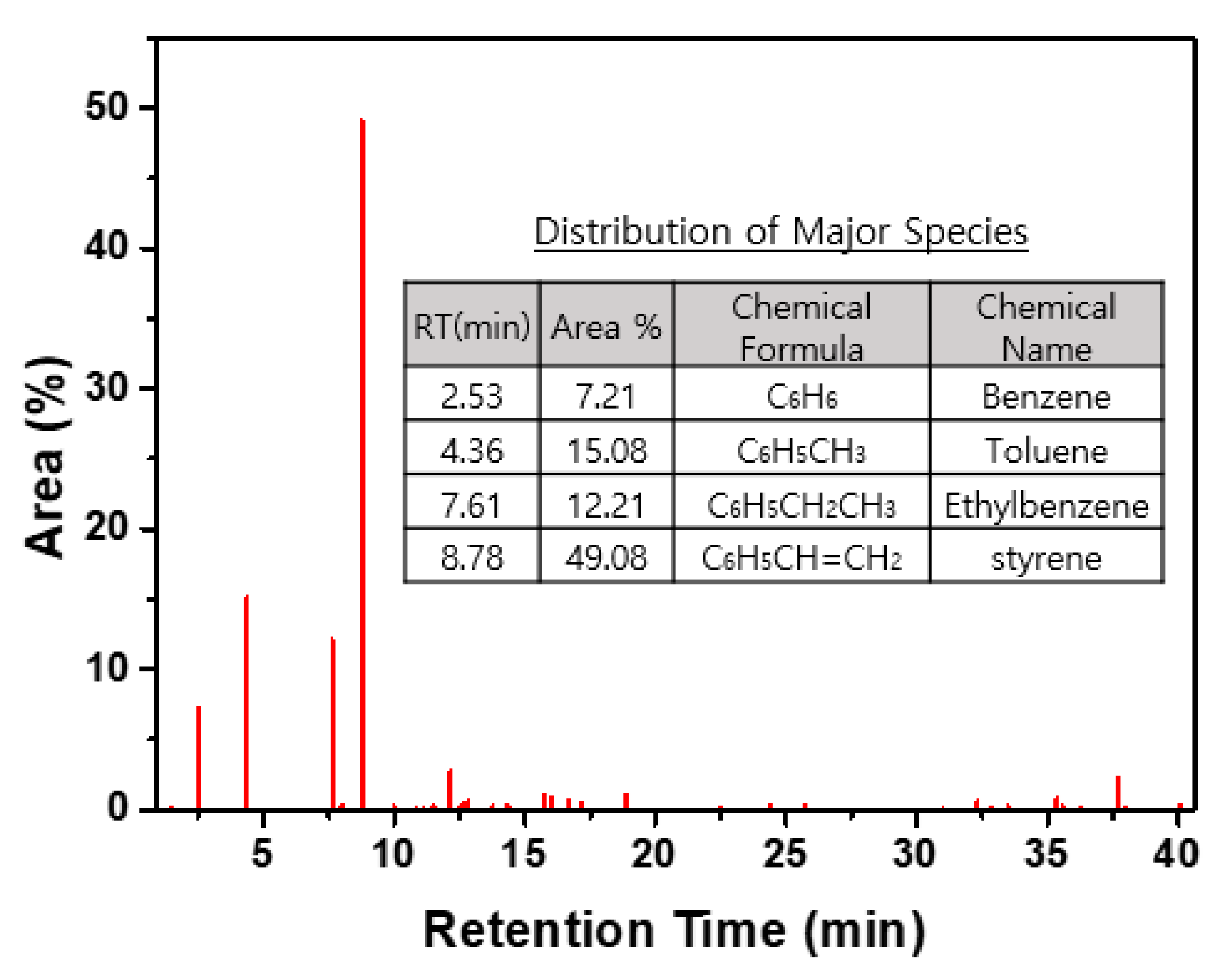
3.3.1. UHCs Generated by the Carbonization of CER

The carbonization process generates a significant amount of UHCs, which should be properly decomposed and oxidized into H2O and CO2. The characteristics of the UHCs generated during the carbonization of CER were investigated using a Py(pyrolysis)-GC/MS (pyrolysis-gas chromatography and mass spectrometer). The instruments used were a portable pyrolyzer (JCI-21) and the HP6890N GC/MS system. The Py-GC/MS result using a pyro-foil at the Curie point temperature of 764 °C are shown in Figure 7. Various types of aromatic hydrocarbons were generated during result pyrolysis of CER. The major UHCs generated were aromatic hydrocarbons. These were C6H6, C6H5CH3, C6H5CH2CH3, and C6H5CHCH2, and their molar compositions based on the peak areas of the GC chromatogram were 7.21%, 15.08%, 12.21%, and 49.08, respectively.

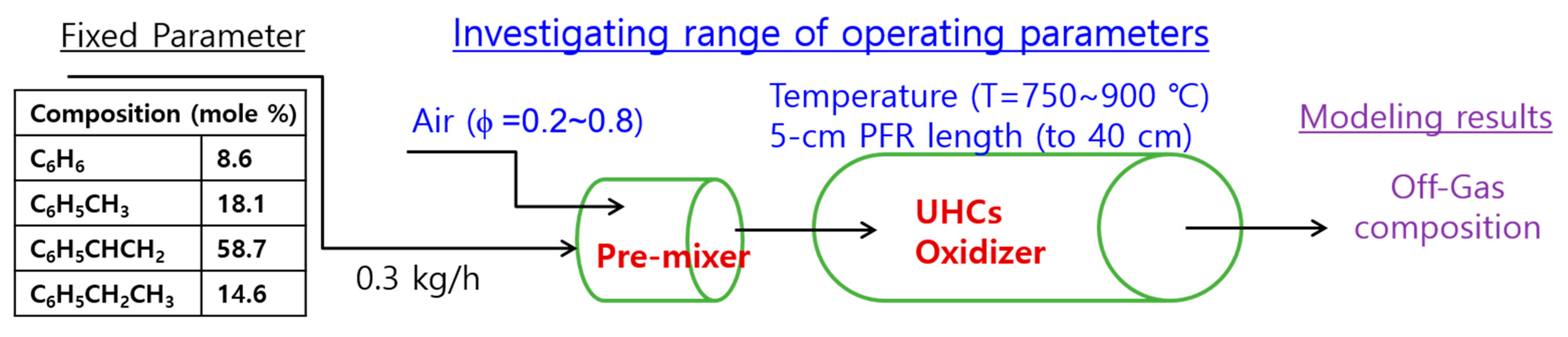
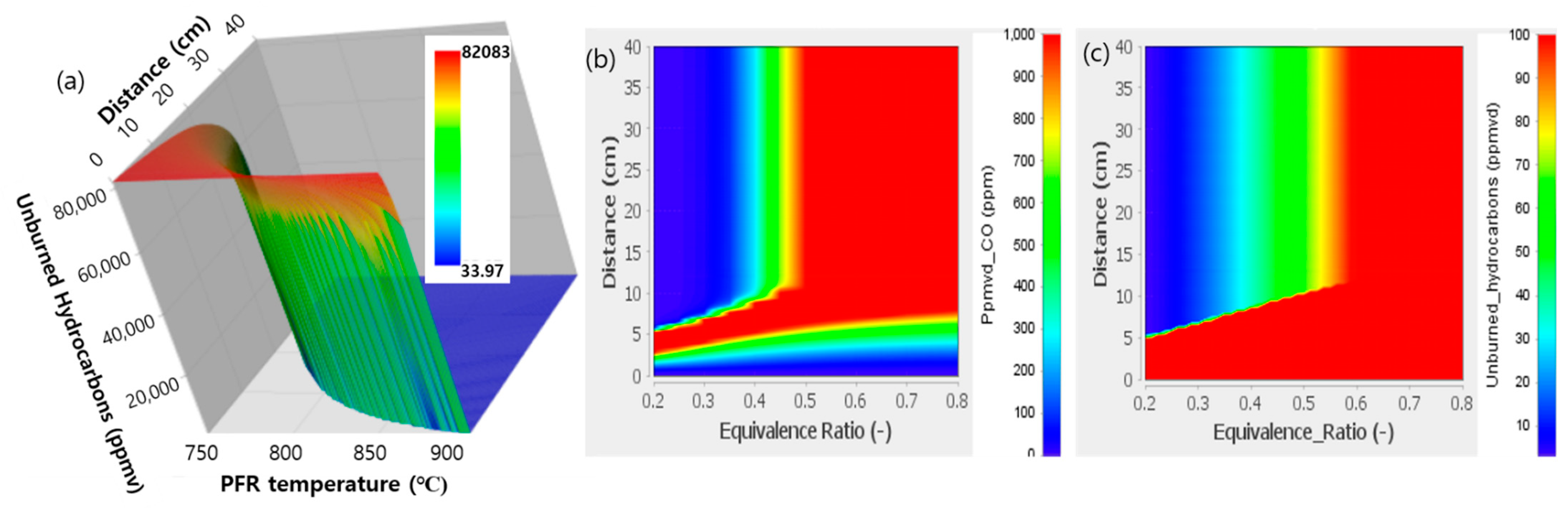
3.3.2. Numerical Determination of the UHC Combustor Operating Condition

A numerical modeling study of the UHC combustor was conducted to design a bench-scale process with a capacity of 5 kg/batch. The simulated conditions for the determination of the UHC combustor operating condition are shown in Figure 8. A cylindrical UHC combustor with a 5 cm inner diameter was assumed as an ideal PFR, in which there is no mixing in the axial direction but perfect mixing in the traverse direction. Parametric model studies of the UHC combustor were performed with ANSYS Chemkin Pro [20]. Chemical kinetic reaction mechanisms for n-alkane hydrocarbons developed by Westbrook et al. [21] were used. The mechanisms were used for the simulation of the combustion of the normalized composition of generated aromatic hydrocarbons (C6H6: 8.6%, C6H5CH3: 18.1%, C6H5CHCH2: 58.7%, and C6H5CH2CH3: 14.6%). It was assumed that SO2 is not involved in the combustion reactions of the UHCs. Based on a treatment rate of 1 kg spent CER/h and a mass loss fraction of the R1 and R2 steps determined by the TGA, as shown in Figure 2, the program input feed rate of gaseous species to the UHC combustor was 0.3 kg/h. The parameters varied for the UHC combustor simulation were the heating temperature, PFR length with a diameter of 5 cm, and equivalence ratio ϕ (the actual air–UHC ratio to the stoichiometric air–UHC ratio for combustion), as shown in Figure 8.
The concentrations of the fed UHCs at a ϕ value of 0.2 and temperature of 750 °C as a function of the reactor distance are shown in Figure 9a. The reactor length of 16 cm is a critical distance for the substantial destruction of fed UHCs under this condition. Figure 9b shows that various types of other aromatic hydrocarbons were newly formed during the thermal decomposition of the fed UHCs. These were also substantially decomposed just before the reactor length of 16 cm. A significant amount of a product of incomplete combustion (PIC), carbon monoxide (CO), however, remained after the reactor length of 16 cm. The carbon monoxide was nearly completely oxidized at the length of ≥20, as shown in Figure 9b.
The reaction pathways of C6H5CH3 and C6H5C2H5 into C6H6 and that of C6H6 into CO2 are depicted in Figure 10. The largest amount of UHC generated by the pyrolysis of CER, with the basic structure of polystyrene, is C6H5C2H5, as shown in Figure 1. C6H5C2H5 is decomposed into C6H6 and CO via C6H5CH2, and C6H5C2H3, respectively, as shown in Figure 10a,b. The C6H5C2H3 was the primary decomposition product of C6H5C2H5. As shown in Figure 10a,b, a significant amount of C6H6 is generated during the course of the thermal decomposition of C6H5C2H5 and C6H5CH3. This explains the delayed decomposition of C6H6 shown in Figure 9a. The concentration of C6H6 was nearly constant to the length of 10 because the decomposition rate of the fed C6H6 is nearly equal to the formation rate of C6H6 due to the decomposition of the fed hydrocarbons until the length of 10 cm. The steep increase in the CO2 concentration during the course of the decomposition of the fed UHCs was due to the rapid increase in the generation of CO with the temperature according to the reaction pathway shown in Figure 10.
The concentrations of the fed UHCs at ϕ value of 0.5 and reactor temperature of 750 °C as a function of the reactor distance are shown in Figure 11a. The critical point of the reactor length is approximately 30 cm for the substantial destruction of the fed UHCs under this condition. Figure 11b shows that the aromatic hydrocarbons generated are also substantially decomposed at the reactor length just before 30 cm. However, 3000 ppm of carbon monoxide (CO) remaining after the reactor length of 16 cm is not further oxidized to 40 cm at a ϕ value of 0.5. The carbon monoxide (CO) cannot be substantially oxidized at a ϕ value of 0.5 and at 750 °C regardless of the reactor length (residence time).
The UHC concentration when ϕ = 0.5 as a function of the PFR length and PFR temperature is plotted in Figure 12a. This 3-D contour plot shows a wide range of UHC combustor operating conditions for the substantial destruction of UHCs. As an example, UHCs are completely decomposed at a temperature of ≥800 °C and PFR length of 10 cm. However, the most critical parameter is the air equivalence ratio, which significantly influences the emission of CO, as shown in Figure 12b,c. In order to lower the emission concentration of CO to a level below the emission standard (100 ppm), ϕ = ≤0.35 is required at 800 °C. The design and operating parameters of the PFR-type UHC combustor were determined as follows: A PFR length of 10 cm (ID = 5 cm), a heating temperature of 800 °C, and a ϕ value of 0.3. The determined appropriate condition will result in the substantial destruction of UHCs and the oxidation of PICs without excess installation and operating costs.

3.4. Determination of the Appropriate Halogenation Condition

The halogenation treatment condition was thermodynamically modelled to determine the ranges of reactor operating temperatures and the feed halogen gas concentration, which is also required for a detailed design and the selection of reactor materials. The mechanism of the vaporization of the elements is the distribution of the elements as a result of chemical reactions within the thermal treatment system. The exact distribution requires knowledge of all constituents, of all the possible reactions, and the reaction rate constants, as conducted for the determination of operating condition for the UHC combustor in this study. Accurate comprehension of the chemical reaction rate data is not available for inorganic elements with gases at high temperatures. In the absence of reaction rate data, it is often assumed that all reactions achieve chemical equilibrium in a relatively short period of time when compared to the total residence time of the reactants [22]. This is a possible approach to the problem, as numerous chemical reactions take place in the system despite the fact that all of the reaction data are not available [23].
The equilibrium model analysis in this study is based on the following assumptions: (1) Thermodynamic equilibrium is maintained in the halogenation reactor, and (2) all of the radioactive species present in the carbonized resins or gas-phase elements in the reactor are intimately mixed. If a given mixture of species undergoes a change that minimizes the total Gibbs free energy, this represents an equilibrium state and corresponds to the complete conversion of the reactants to products. The Gibbs energy function of a system is expressed as
G =   k = 1 K g ¯ k N k ,
where g ¯ k is the partial molar Gibbs energy function and N k is the number of moles of each species k in the system; K is the total number of species. For ideal-gas mixtures or ideal solutions, the partial molar Gibbs function is given by
g ¯ k = g k ( T , P ) + R T ln X k ,
where g k ( T , P ) is the Gibbs function for the pure species k evaluated at the system temperature and pressure, R is the universal gas constant, and X k is the mole fraction of the k th species. The equilibrium solution at a given temperature and pressure is the distribution of N k that minimizes the system Gibbs energy function G subject to atomic population constraints (and a non-negative N k ). The atomic population constraints are as follows:
k = 1 K n j k N k = P j ,   j = 1 , M
Here, n j k is the number of the j th atoms that appear in the k th molecule, P j denotes the total population in moles of the j th atom in the system, and M is the total number of different elements present in the system. HSC-Chemistry 7.1 software was used for the model calculation [24]. The simulated compositions of the carbonized spent CER and chlorination gas are shown in Table 1. The simulated mixing ratio of the condensed phase material (carbonized resin) to the chlorination gas was unity.
The calculated results for the equilibrium mole fractions of the nonradioactive compounds and radioactive compounds are shown in Figure 13a,b respectively. Carbon, the major component of carbonized CER, plays an important role in the conversion of inorganic elements into volatile chlorides. As shown in Table 1, inorganic elements exist in the form of their respective sulfides, which are relatively stable at high temperatures. Figure 13a shows the increased mole fractions of S(g) and CO(g). This indicates that metal sulfides are readily reduced and chlorinated in the presence of carbon and chlorine. The following reaction, expressed by Equations (9) and (10), shows the significant role of carbon during the volatilization of metals in the form of nonvolatile sulfate. Calcium sulfate (CaSO4) is a non-volatile compound at approximately ≤1500 °C. As an example, as shown in Equation (9), CaSO4 is not converted into its volatile chloride (CaCl2) in the presence of chlorine at 1400 °C. However, in the presence of carbon, CaSO4 is readily converted into its volatile chloride (CaCl2), even at a much lower temperature of 1000 °C.
CaSO4 + Cl2(g) = CaCl2(g) + SO2(g) + O2(g) ΔG = +10.9 kJ/mole at 1400 °C
CaSO4 + Cl2(g) + 2C = CaCl2(g) + S(g) + 4CO(g) ΔG = ‒329.7 kJ/mole at 1000 °C
Figure 13b shows the thermodynamically stable forms of the radioactive elements and their respective volatile chlorides at a temperature of ≥1130 °C. If we continuously flow chlorine gas through the bed of the carbonized resin granules at ≥1200 °C, we can readily remove metallic and radioactive elements from the granules.

4. Installation of a Bench-Scale Process and Test Operation

4.1. Process Description

The thermochemical decontamination process is a two-stage process of carbonization and halogenation. Figure 14 shows the arrangement of unit for the proposed thermochemical processes. The key units are a carbonization/halogenation reactor, the UHCs (unburned hydrocarbons), a combustor, and a wet acid gas scrubber. The detailed designs of the carbonization/halogenation reactor and PFR-type UHC combustor were created based on the results of a numerical modeling study. During the first stage of the treatment, the pyrolysis and carbonization of the spent CER, significant amounts of H2O, SO2, and UHCs are generated. To prevent the oxidation loss of graphite materials in the multifunctional reactor, a vacuum condition is maintained without supplying nitrogen during the course of carbonization. The complete sealing of the multifunctional reactor and the installation of a vacuum pumping system, as shown in Figure 14, were required for this purpose.
UHCs are treated by the PFR-type combustor with a 5 cm ID and a 20 cm L with a supply of combustion air of ϕ = 0.3 according to the determined a condition. SO2 is collected in a conventional wet scrubber with an alkaline (NaOH) solution. During the second stage of the treatment, halogenation of pyrocarbon bearing radionuclides at a higher temperature generates vapors of metal/radionuclide halides. The vapors of these metallic species then condense into particulates as the off-gas cools. This is done by passing them through the wet scrubber, which is operated under atmospheric temperatures. Some portion of the particulates is collected in the wet scrubber and the remainder is collected in the HEPA filter with a collection efficiency of ≥99.97% for 0.3 μm particles. In this manner, the generated flue gas bearing hazardous constituents with the acid gas (SO2), UHCs, and vapors of hazardous/radioactive metal species are substantially collected at a level below the emission standards.
Two important advantages of the proposed process are the smaller plant size and the lower volume of the final radwaste requiring disposal. The generated volume of off-gas is much smaller because most of the carbon species in the CER are not gasified or combusted. This results in a smaller plant size when compared to that of a conventional radwaste incineration plant. In the proposed process, only inorganic elements are vaporized and collected as secondary radioactive waste. No carbon-bearing fly-ash due to the turbulence of combustion gas is generated during the proposed thermochemical process. Therefore, no primary filtering system, such as a bag-filter system, is required. These advantages result in a much smaller volume of secondary waste as well as a much smaller size of the off-gas treatment system.

4.2. Detailed Design of the Multifunctional Reactor and Test Results

The detailed design of the multifunctional reactor for the carbonization of the CER, images of the inside of the reactor after the feeding of the CER and after the treatment, and the results of the SEM-EDS (Scanning Electron Microscope-Energy Dispersive X-ray Spectrometer) analysis of the carbonized CER and the chlorination-treated carbonized CER are shown in Figure 15. As shown in Figure 15a, all reactor components are made of graphite, as graphite is the only material available that can endure halogen gases at very high temperatures. The processing materials, spent CERs, are spherical granules with diameters 0.3~0.8 cm in size. Therefore, a type of vertical packed-bed reactor, through which a carrier gas or a reacting gas flows up, is used as a multifunctional reactor. This multifunctional reactor conducts two different reacting processes in a stepwise manner.
Basic performance tests using CER doped with nonradioactive Co and Cs with an initial mass content of 0.1% of each metal were conducted under the determined appropriate carbonization and halogenation treatment conditions. Simulated spent CERs doped with nonradioactive Co and Cs were loaded into the packed-bed reactor. The reactor was then heated to 800 °C and this temperature was sustained for 40 min under a N2 flowing condition according to the appropriate carbonization temperature and time profile shown in Figure 6. After this carbonization step was complete, the temperature of the reactor was raised further to 1500 °C by flowing Cl2 and this stage was sustained for one hour. The results of a SEM-EDX analysis of carbonized CER and halogenation-treated carbonized CER shown in Figure 15d,e present the substantial removal of surrogate metals in the spent CER, Co, and Cs, by the applied carbonization and halogenation treatment. The results of these tests demonstrate that the noble thermochemical process proposed in this study is a viable process that effectively removes radioactive elements from spent CER. The required processing time for the halogenation treatment for the substantial removal of all radionuclides from spent CER to reduce their concentrations to levels below the free-release criteria will be determined by demonstration treatment of actual radioactive spent CER.

5. Conclusions

A novel thermochemical process for the removal of radionuclides from spent cation-exchange resins was proposed in this study. A step-by-step experimental and numerical modeling study was conducted for the design and establishment of the proper operation conditions for the carbonization and halogenation reactor and the UHC combustor. Based on the results of experimental and modeling study, an integrated process consisting of a multifunctional reactor made of graphite, which can safely conduct the halogenation treatment at a very high temperature, was realized. The optimum operating conditions could be established based on the results of a thermal analysis of the CER, a nonisothermal kinetic analysis, a numerical modeling study of a PFR-type combustor, and a thermodynamic equilibrium composition analysis. The results of this study present detailed design of a novel multifunctional reactor and operating conditions of a bench-scale carbonization and halogenation process. The results of basic performance tests using nonradioactive surrogates showed that the thermochemical process proposed here is an executable process that effectively removes radioactive elements from spent CER.

Author Contributions

Conceptualization, methodology and software, H.-C.Y.; experiment, H.-C.Y., H.-O.P. and K.-T.P.; discussion: H.-C.Y., H.-J.K., H.-C.E. and S.-J.K.; writing and editing, H.-C.Y.; project administration, H.-C.Y. and K.L. All authors have read and agreed to the published version of the manuscript.

Funding

This research received no external funding.

Acknowledgments

This research was supported by the National Research Foundation of Korea (NRF), which is funded by the Ministry of Science, ICT and Future Planning (MSIP) of the Republic of Korea (NRF-2017-M2A8A5015147) and by the Korean Institute of Energy Technology Evaluation and Planning (KETEP-2020311010050).

Conflicts of Interest

The authors declare no conflict of interest.

References

  1. Zhang, J.; Qian, H. Thermal behavior of weak basic ion exchange resin. J. Therm. Anal. Calorim. 2014, 115, 875–880. [Google Scholar] [CrossRef]
  2. Mohammad, A.; Inamuddin, A.A.; Nuashad, M.; Eldesoky, G.E. Forward ion-exchange kinetics of heavy metal ions on the surface of carboxymethyl cellulose Sn(IV) phosphate composite nano-rod-like exchanger. J. Therm. Anal. Calorim. 2012, 110, 715–723. [Google Scholar] [CrossRef]
  3. Wang, J.; Wan, Z. Treatment and disposal of spent radioactive ion-exchange resins produced in the nuclear industry. Prog. Nucl. Energy 2015, 78, 47–55. [Google Scholar] [CrossRef]
  4. Chun, U.K.; Choi, K.S.; Yang, K.H.; Park, J.K.; Song, M.J. Waste minimization pretreatment via pyrolysis and oxidative pyrolysis of organic ion exchange resin. Waste Manag. 1998, 18, 183–196. [Google Scholar] [CrossRef]
  5. Antonetti, P.; Claire, Y.; Massit, H.; Lessart, P.; Van Cang, C.P.; Perichaud, A. Pyrolysis of cobalt and caesium doped cationic ion-exchange resin. J. Anal. Appl. Pyrolysis 2000, 55, 81–92. [Google Scholar] [CrossRef]
  6. Barton, R.G.; Clark, W.G.; Seeker, W.R. Fate of metals in waste combustion systems. Combust. Sci. Technol. 1990, 74, 328–336. [Google Scholar] [CrossRef]
  7. Georg, B.; Rainer, S. Pyrolysis of spent ion exchange resins. In Proceedings of the Nuclear Plant Chemistry Conference 2012 (NPC 2010), Quebec City, QC, Canada, 3–7 October 2012; pp. 23–27. [Google Scholar]
  8. Masami, M.; Kiyomi, F.; Makoto, K. Decomposition of Ion Exchange Resins by Pyrolysis. Nucl. Technol. 1986, 75, 187–982. [Google Scholar]
  9. Peterson, S.; Kemmler, G. Experience of Resin Pyrolysis; Waste Management: Tuscon, AZ, USA, 1984. [Google Scholar]
  10. Matsuda, M.; Funabashi, K.; Yusa, H. Influence of functional sulfonic acid group on pyrolysis characteristics for cation exchange resin. J. Nucl. Sci. Technol. 1987, 24, 124–128. [Google Scholar] [CrossRef]
  11. Michlink, D.L.; Marchall, R.W.; Smith, K.R.; Turner, V.C.; Vander Wall, E.M. The Feasibility of Spent Resins Incineration at Nuclear Power Plants; Waste Management: Tuscon, AZ, USA, 1983; pp. 439–441. [Google Scholar]
  12. Chiara, S.; Alessio, F.; Alberto, C.; Tiziano, F.; Eliseo, R. A wide range kinetic modeling study of pyrolysis and oxidation of benzene. Combust. Flame 2013, 160, 1168–1190. [Google Scholar]
  13. Ho, T.C.; Kuo, T.H.; Hopper, J.R. Thermodynamic study of the behavior of uranium and plutonium during thermal treatment under reducing and oxidizing modes. Waste Manag. 2000, 50, 355–361. [Google Scholar] [CrossRef]
  14. Barbin, N.M.; Terentiev, D.I.; Alexeev, S.G.; Barbina, T.M. Thermodynamic analysis of radionuclides behaviour in products of vapour phase hydrothermal oxidation of radioactive graphite. J. Radioanal. Nucl. Chem. 2016, 307, 1459–1470. [Google Scholar] [CrossRef]
  15. Yang, H.C.; Lee, S.Y.; Choi, Y.C.; Yang, I.H.; Chung, D.C. Thermokinetic analysis of spent ion-exchange resins for the optimization of carbonization reactor condition. J. Therm. Anal. Calorim. 2017, 127, 587–595. [Google Scholar] [CrossRef]
  16. Vyazovkin, S.; Burnham, A.K.; Criado, J.M.; Pérez-Marqueda, L.A.; Popescu, C.; Sbirrazzuoli, N. ICTAC Kinetics Committee recommendations for performing kinetic computations on thermal analysis data. Thermochim. Acta 2011, 520, 1–19. [Google Scholar] [CrossRef]
  17. Friedman, H.L. Kinetics of thermal degradation of char-forming plastics from thermogravimetry—Application to a phenolic plastic. J. Polym. Sci. 1964, 6, 183–195. [Google Scholar] [CrossRef]
  18. Roduit, B.; Borgeat, C.; Berger, B.; Folly, P.; Alonso, B.; Aebischer, J.N.; Stoessel, F. Advanced kinetic tools for the evaluation of decomposition reactions. J. Therm. Anal. Calorim. 2005, 80, 229–236. [Google Scholar] [CrossRef]
  19. Yang, H.C.; Lee, M.W.; Eun, H.C.; Kim, J.H.; Lee, K.; Seo, B.K. Thermal decontamination of spent activated carbon contaminated with radiocarbon and tritium. Processes 2020, 8, 1359. [Google Scholar] [CrossRef]
  20. ANSYS. Chemkin-Pro, Chemistry Solution for More Efficient Designs; ANSYS, Inc.: Canonsburg, PA, USA, 2016; Available online: https://www.ansys.co17m/-/media/ansys/corporate/resourcelibrary/brochure/chemkin-pro-brochure.pdf (accessed on 11 November 2020).
  21. Westbrook, C.K.; Pitz, W.J.; Herbinet, O.H.J.; Curran, H.J.; Silke, E.J. A detailed chemical kinetic reaction mechanism for n-alkane hydrocarbons from n-Octane to n-Hexadecane. Combust. Flame 2009, 156, 181–199. [Google Scholar] [CrossRef] [Green Version]
  22. Yang, H.C.; Eun, H.C.; Lee, D.G.; Oh, W.Z.; Lee, K.W. Behavior of radioactive elements during thermal treatment of nuclear graphite–thermodynamic model analysis. J. Nucl. Sci. Technol. 2005, 42, 869–876. [Google Scholar] [CrossRef]
  23. Durlak, S.K.; Biswas, P.; Shi, J. Equilibrium analysis of the affect of moisture and sodium content on heavy metal emissions from municipal solid waste incinerators. J. Hazard. Mater. 1996, 56, 1–20. [Google Scholar] [CrossRef]
  24. Outokumpu Research. HSC Chemistry 7.1—Chemical Reaction and Equilibrium Software with Extensive Thermodynamic Database; Outotec Research Center: Pori, Finland, 2015. [Google Scholar]
Figure 1. Chemical structure of the strong acidic cationic ion exchange (IE) resins with functional groups of –SO3H+ and ion-exchange mechanisms of two typical ions of a one-valence-count ion (Cs+) and a two-valence-count ion (Co2+).
Processes 09 00096 g001
Figure 2. Principle of the carbonization and halogenation treatment process for the removal of radionuclides from spent ion-exchange resins.
Processes 09 00096 g002
Figure 3. Changes of the sample weight (TG) and derivative of the samples weight (dTG) at elevated temperatures, and SEM image of dried sample and those after the R1, R2, and R3 reaction steps.
Processes 09 00096 g003
Figure 4. Weight changes of cation-exchange resin (CER) (a) and the reaction rates (b) determined by the nonisothermal TGAs with different heating rates of 0.5, 1.0, 1.5 and 2.0 K/min.
Processes 09 00096 g004
Figure 5. Plots for the determination of the activation energy Eα (a) and the determined modified pre-exponential factor A′(α) (=Aα f(α)) for reaction step R3 (b).
Processes 09 00096 g005
Figure 6. Optimized carbonization reactor heating condition for the completion of carbonization reaction step (R3) with a slow ramping rate to 800 °C to avoid the sudden generation of a large amount of UHCs.
Processes 09 00096 g006
Figure 7. Py-GC/MS result when using a pyro-foil at the Curie point temperature of 764 °C and distribution of the major species of UHCs.
Processes 09 00096 g007
Figure 8. Simulated conditions for the determination of the unburned hydrocarbon (UHC) combustor operating condition.
Processes 09 00096 g008
Figure 9. Concentrations of fed UHCs (a) and those of newly formed UHCs and CO (b) at a ϕ value of 0.2 and temperature of 750 °C as a function of the reactor distance.
Processes 09 00096 g009
Figure 10. Reaction pathways of C6H5CH3 (a) and C6H5C2H5 (b) into C6H6, and that of C6H6 (c) into CO2.
Processes 09 00096 g010
Figure 11. Concentrations of fed UHCs (a) and those of newly formed UHCs and CO (b) at a ϕ value of 0.5 and temperature of 750 °C as a function of the reactor distance.
Processes 09 00096 g011
Figure 12. UHC concentration at ϕ = 0.5 as a function of the plug flow reactor (PFR) length and PFR temperature (a), and concentrations of CO (b) and UHCs (c) at 800 °C as a function of the PFR distance and air equivalence ratio (ϕ).
Processes 09 00096 g012
Figure 13. Calculated results for equilibrium mole fractions of nonradioactive compounds (a) and radioactive compounds (b).
Processes 09 00096 g013
Figure 14. Arrangement of units for the proposed thermochemical processes.
Processes 09 00096 g014
Figure 15. Detailed design of the multifunctional reactor implementing carbonization of CER (a), pictures of the reactor after the feeding of the CER (b) and after the treatment (c), and the SEM-EDS results of the carbonized CER (d) and chlorination-treated carbonized CER (e).
Processes 09 00096 g015
Table 1. Chemical composition of carbonized CER and chlorination gas for the equilibrium model calculation for the determination of the appropriate chlorination reactor condition.
Carbonized CER (Mole %)Chlorination Gas (mole %)
Non-Radioactive Compounds (wt.%)Radioactive Compounds (×10−6)
C0.80134/137Cs2SO40.007Cl20.1
Na2SO40.02558/60CoSO40.012N20.8998
CaSO40.000690SrSO40.008O20.0001
Fe(+59Fe) SO40.002354MnSO40.01H2O0.00005
Cr2(SO4)30.001165ZnSO40.006CO20.00002
MgSO40.0004695Zr (SO4)20.004
NiSO40.000041
Publisher’s Note: MDPI stays neutral with regard to jurisdictional claims in published maps and institutional affiliations.

