Research on the Dynamic Characteristics of Mechanical Seal under Different Extrusion Fault Degrees

Abstract
1. Introduction
2. Analysis of Sealing Fault Mechanism
2.1. Normal State
2.2. Fault State
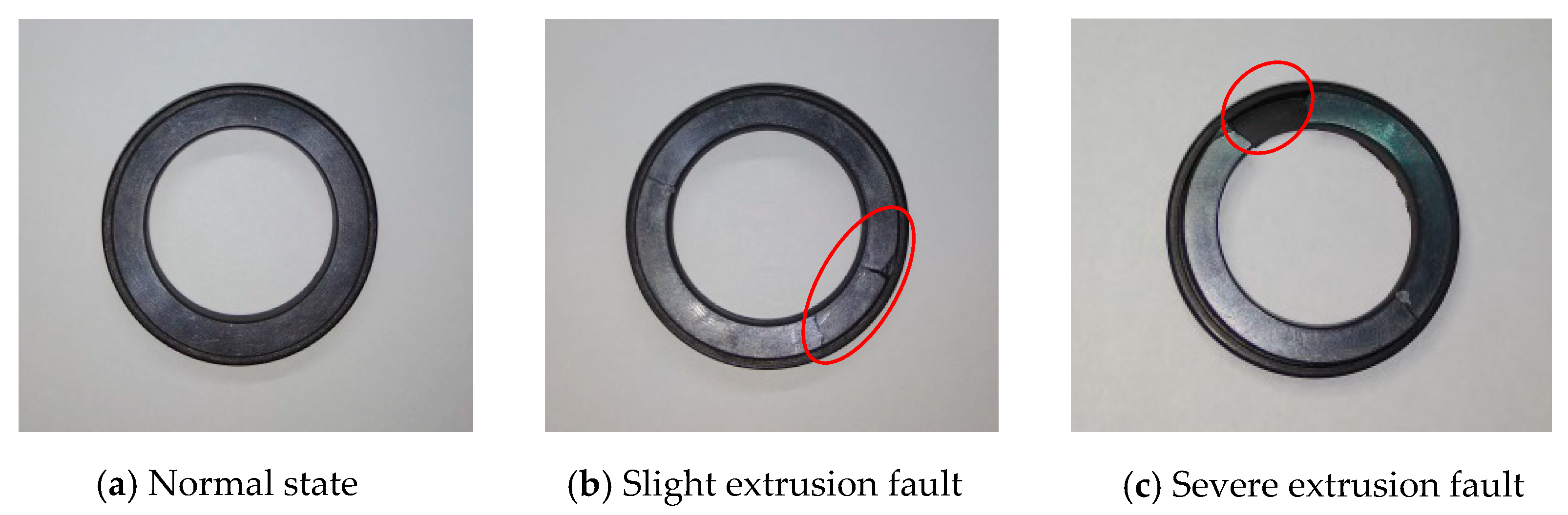
2.3. Extrusion Faults
3. Establishment of Calculation Model
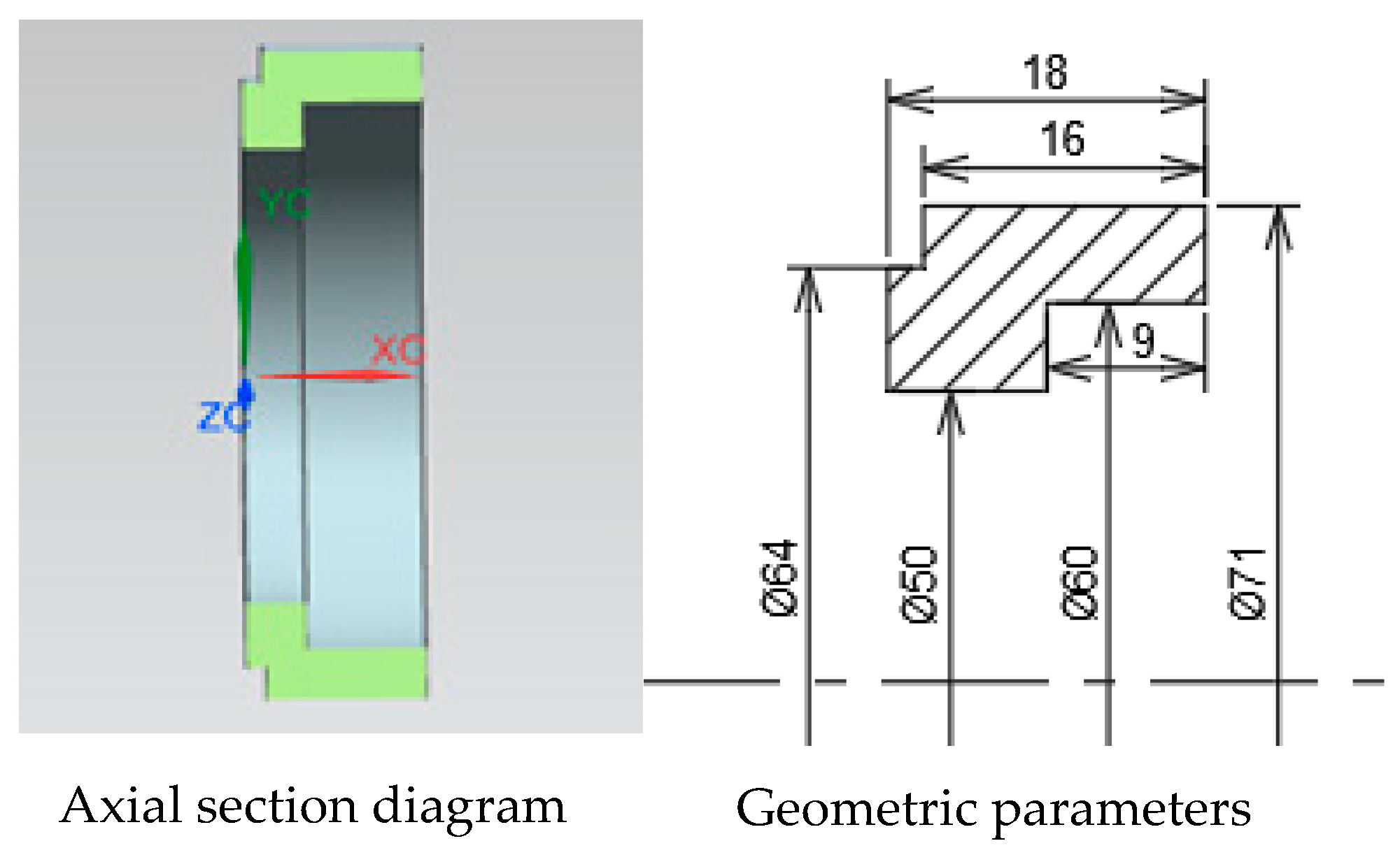
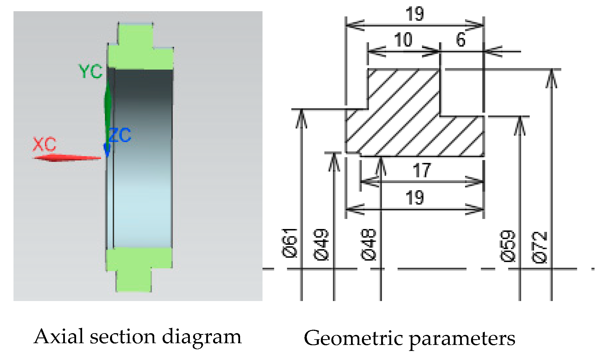
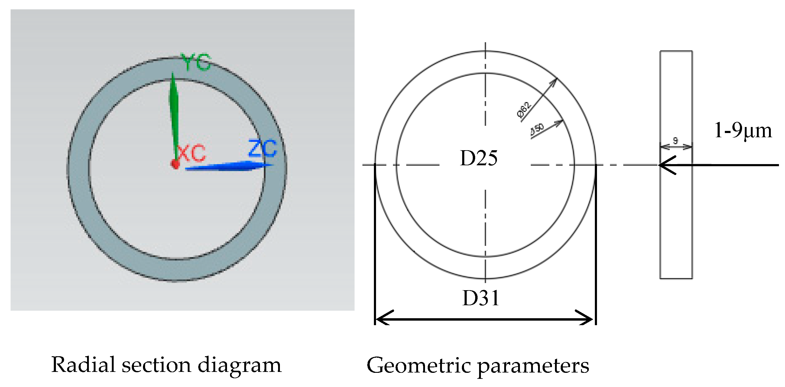
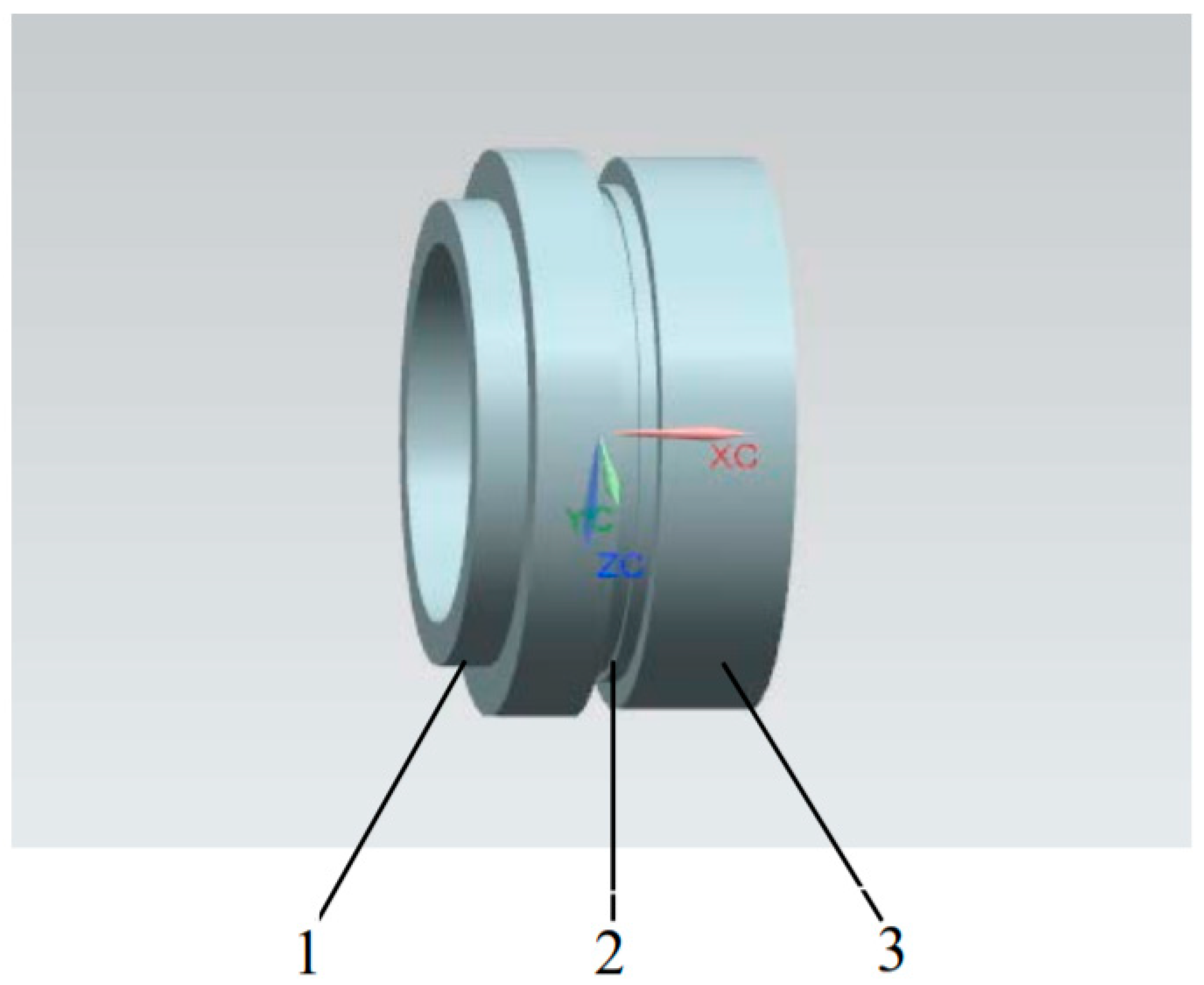
3.1. Fault Physical Models
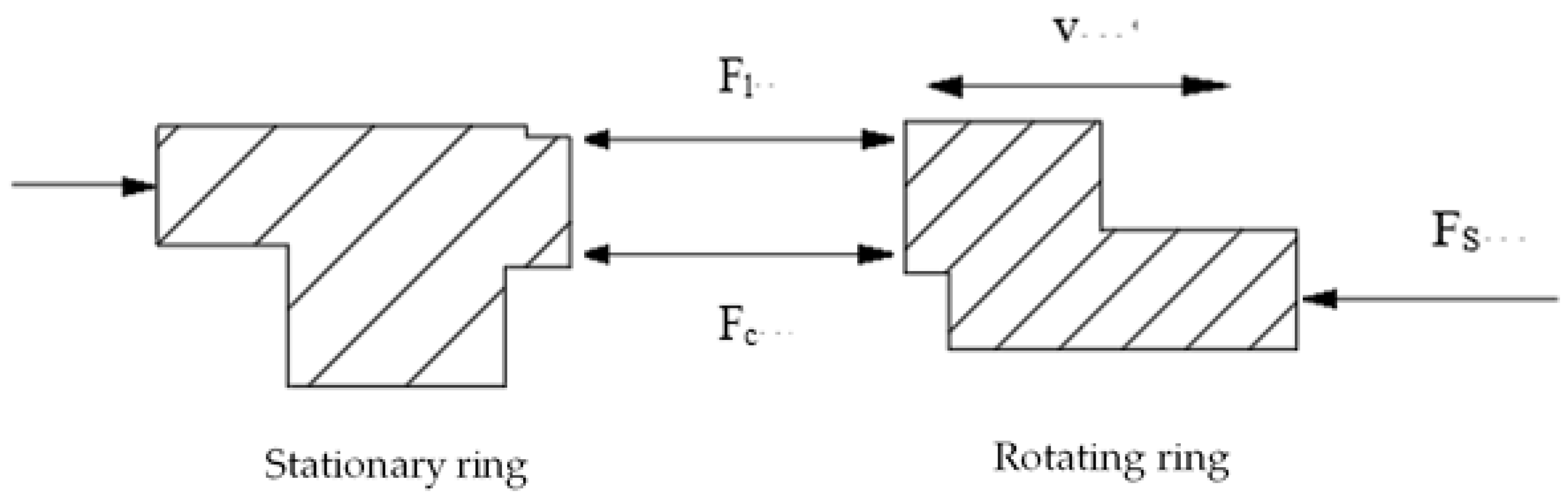
3.2. Dynamic Calculation Model
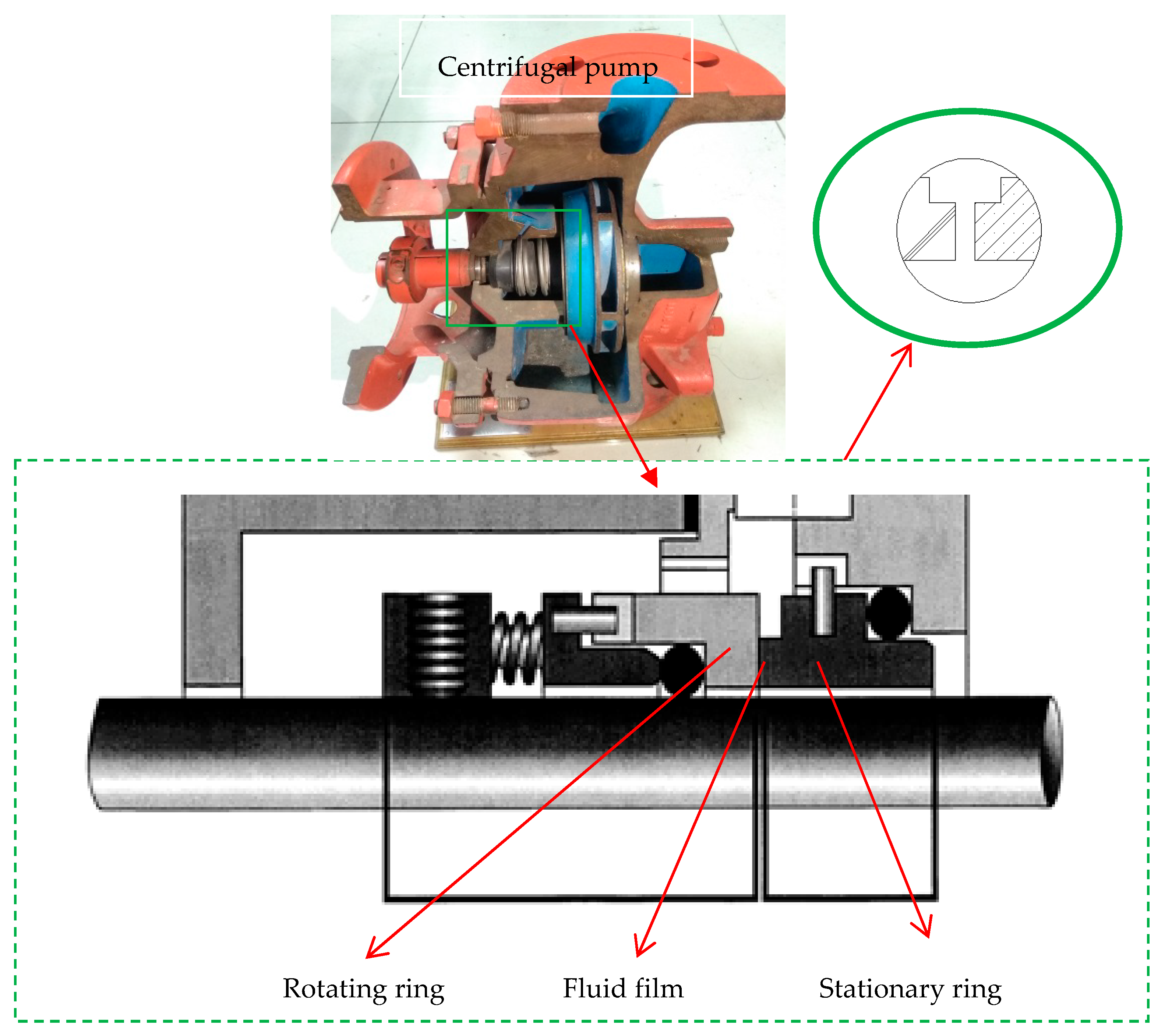
- Mechanical seal consists of rotating ring, fluid film, stationary ring, and auxiliary system, the rotating ring part was provided with elastic force by the elastic element. The fluid film was formed by the liquid between the rotating and stationary ring. The stationary ring is a static part of the mechanical seal. The mechanical seal is simplified to simulate the process of faults conveniently. Thus, it is simplified into three parts: rotating ring, stationary ring, and fluid film.
- Because the distance between the rotating ring and the stationary ring is quite close and the thickness of the fluid film is tiny in the actual work of mechanical seal, the fluid film conforms to the Newton’s law of viscosity and the effect of volume force and inertia force is ignored.
- The sealing medium is generally an incompressible fluid, but the density would change with pressure in this paper.
- It is assumed that the heat generated by friction is only transferred between the rotating and stationary rings of the mechanical seal, and the heat loss caused by stirring, thermal radiation, and leakage is ignored.
- It is assumed that the fluid has no velocity slip on the solid boundary.
3.2.1. Control Equations
- Fluid Domain Equation
- 2.
- Solid Domain Equation
- 3.
- Dynamic Model of Axial Movement
3.2.2. Sealing Performance Parameters
- Seal Opening Force
- 2.
- Leakage of Mechanical Seal
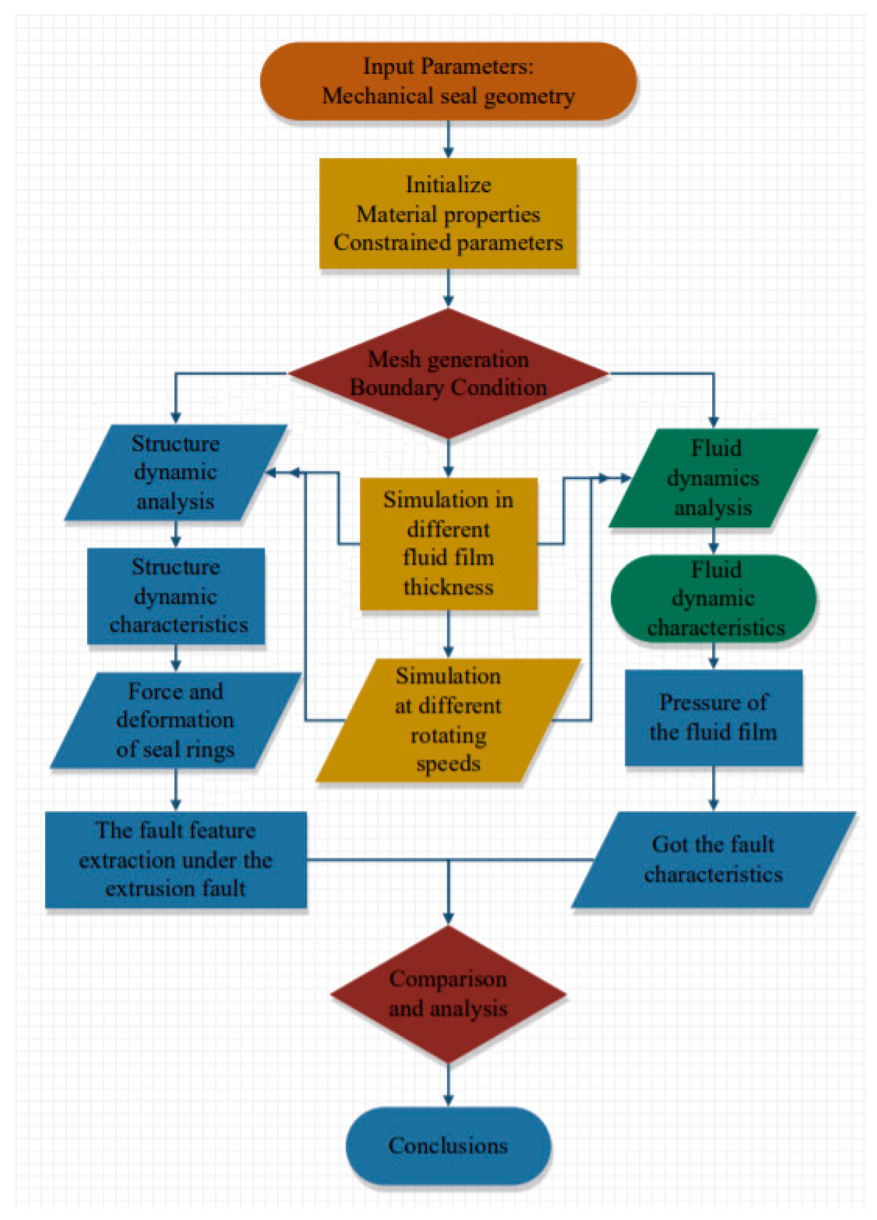
4. Dynamic Simulations and Analysis
5. Results and Discussion
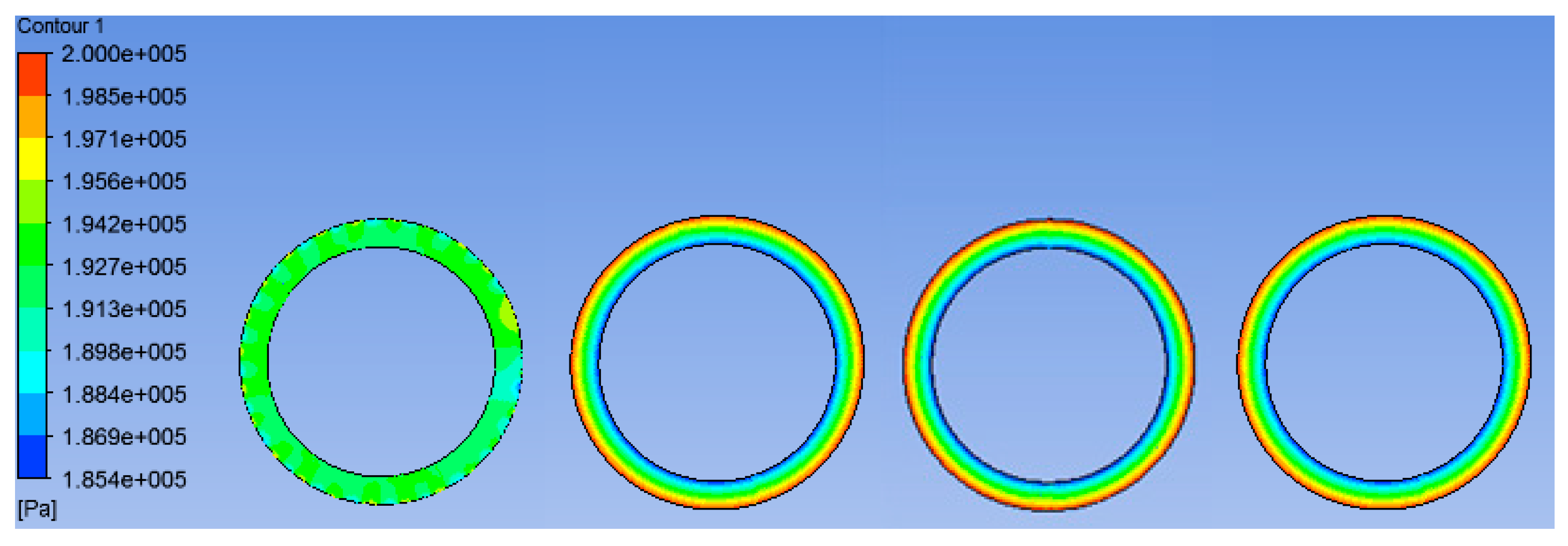
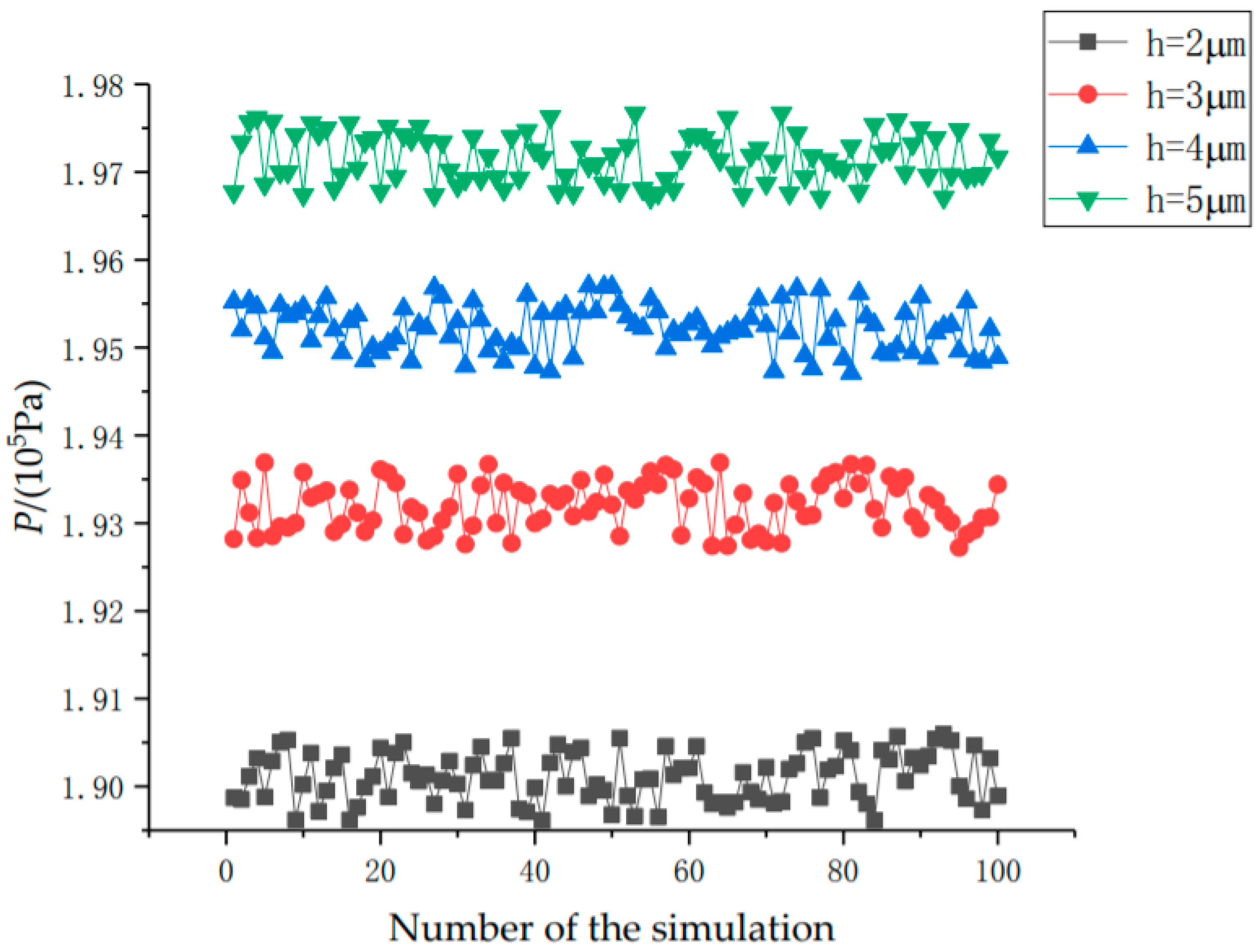
5.1. Fluid Film Pressure Analysis
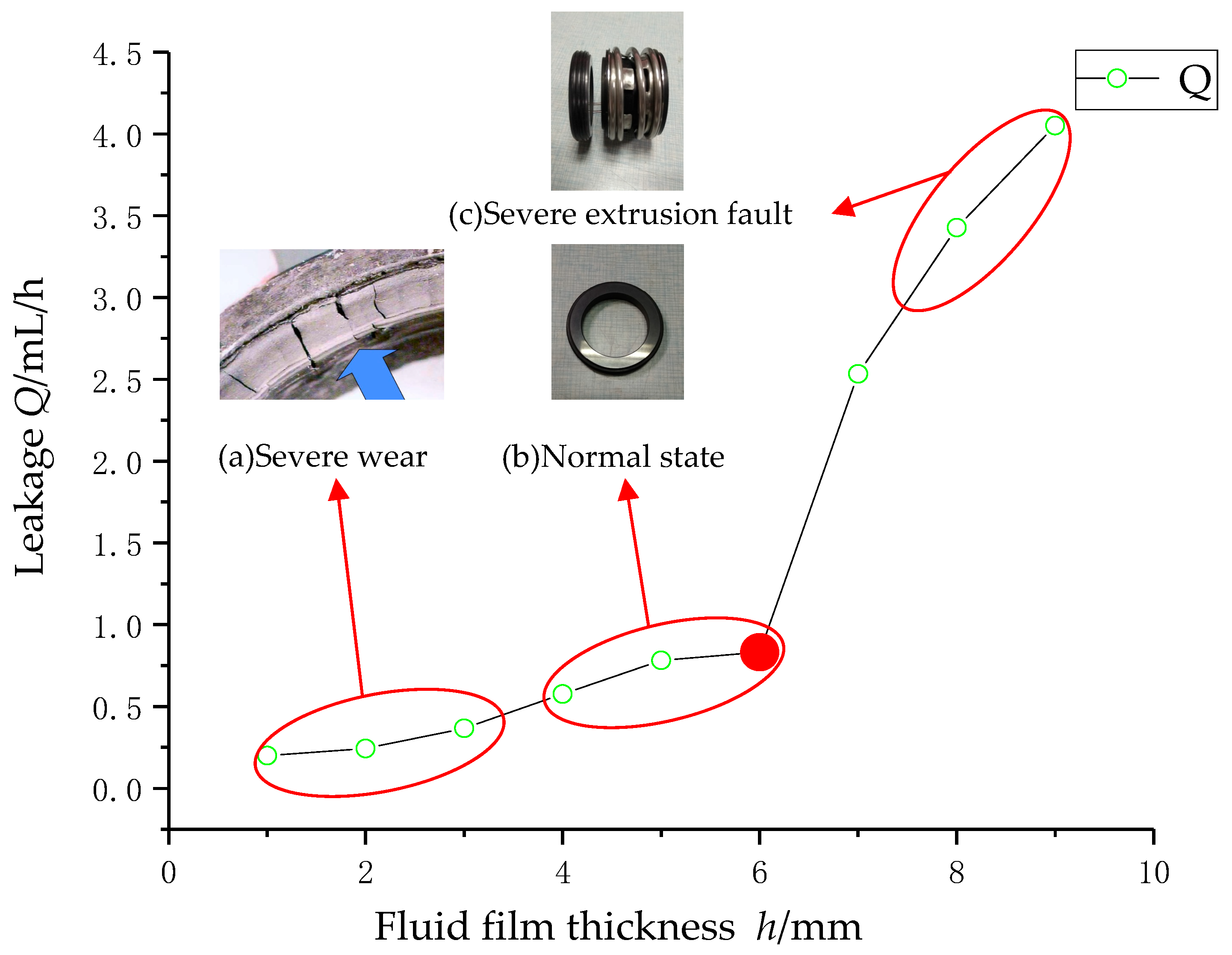
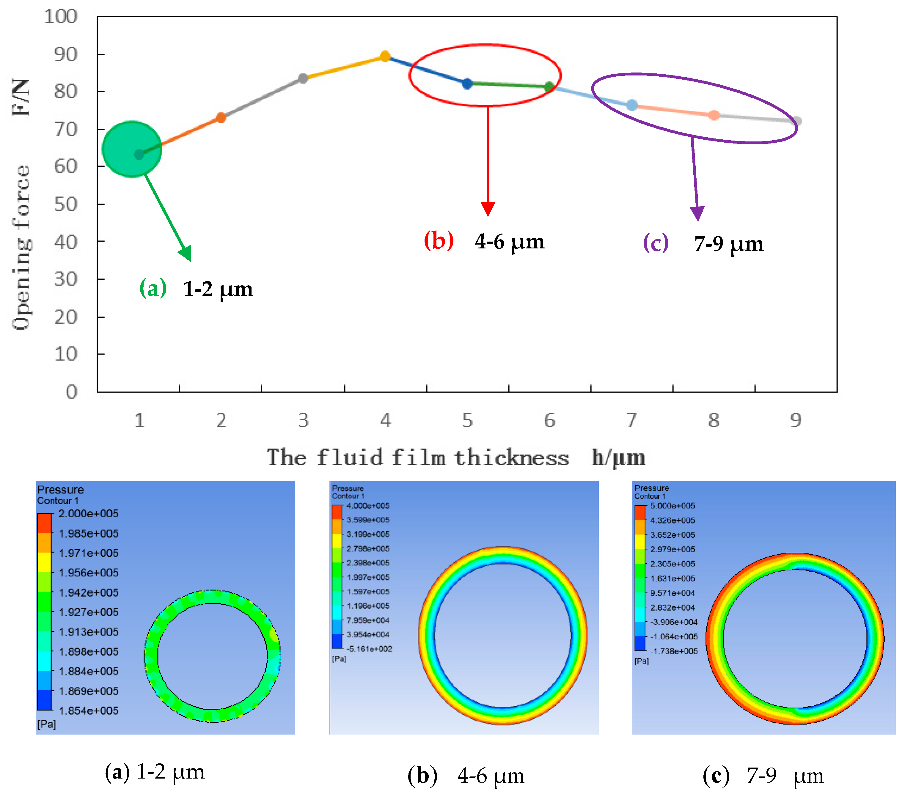
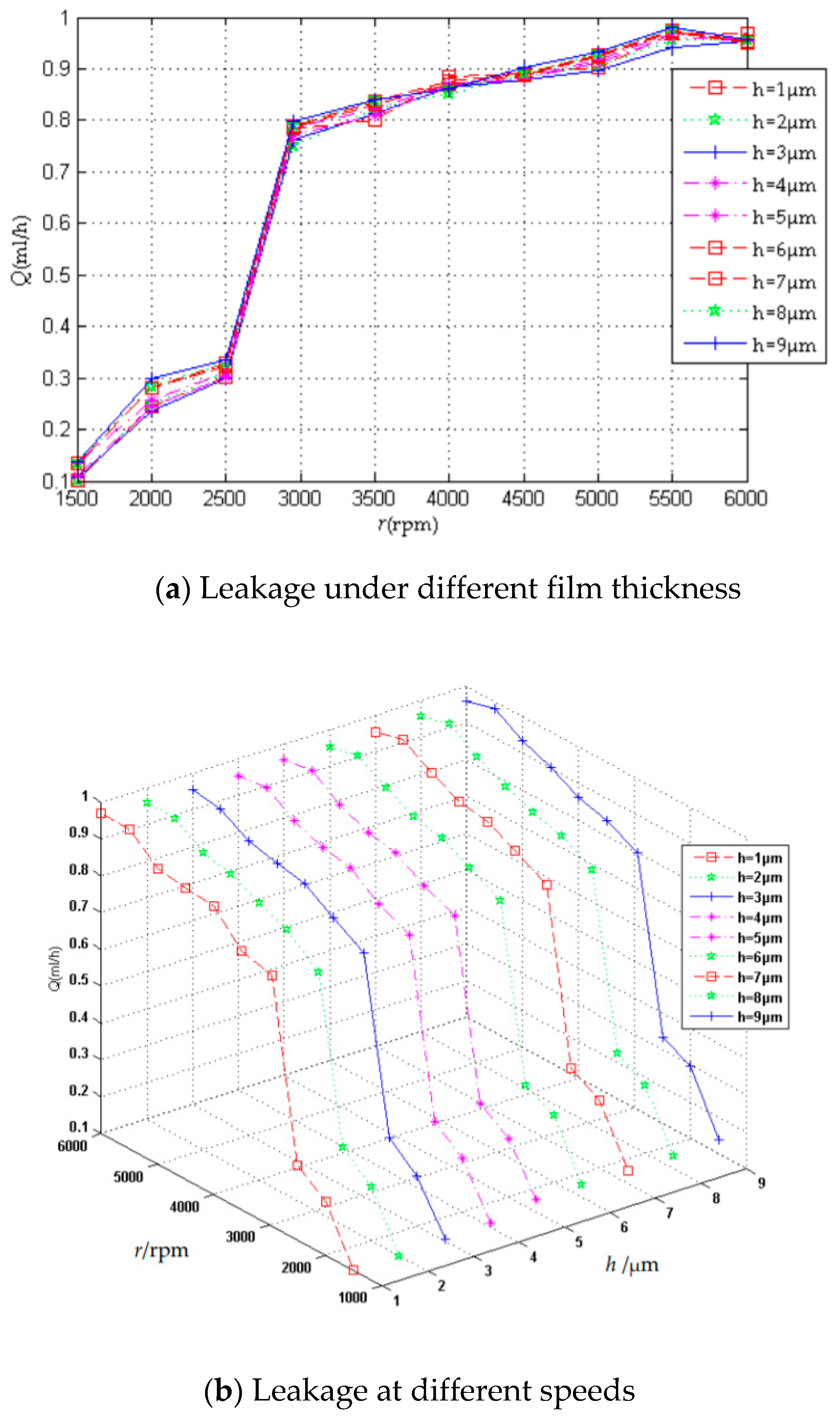
5.2. Seal Performance Analysis
6. Conclusions
- It was the first time to do research on the dynamic characteristics of mechanical seal in the different fault degrees, and proved feasibility of this method. Meanwhile, the leakage Q, opening force F, rotating speed n were combined for the research on seal performance, fault mechanism, and fault degrees analysis.
- The leakage analysis of mechanical seal in the different degrees of extrusion fault was conducted with the increasing of fluid film thickness. The extrusion fault is more likely to occur when the fluid film thickness is too large or too small. As the fluid film thickness beyond the best thickness area, the hydrodynamic effects of fluid film turn weaker, while volume force and inertia force get larger. Such tendency has the reference value of mechanical seal fault detection.
- The leakage and opening force present obvious change of fluid film thickness. With the increasing of rotating speeds, the leakage grows with many fluctuations. Based on the combined action of the hydrodynamic and fluid film stiffness, the seal leakage could reflect the sealing performance and the seal fault. There must be a law between the extrusion degrees and fluid film thickness. This paper researched the law that too thin or too thick fluid film would result in the heavy extrusion fault. The fluid film stiffness, leakage, and opening force are the important parameters, which have recognition capability for the extrusion degrees of the mechanical.
Author Contributions
Funding
Conflicts of Interest
References
- Beckerle, P.; Schaede, H.; Rinderknecht, S. Fault diagnosis and state detection in centrifugal pumps—A review of applications. In Proceedings of the 9th IFToMM International Conference on Rotor Dynamics; Springer: Cham, Switzerland, 2015; pp. 387–398. [Google Scholar] [CrossRef]
- Ma, X.; Meng, X.; Wang, Y.; Peng, X. Suction effect of cavitation in the reverse-spiral-grooved mechanical face seals. Tribol. Int. 2019, 132, 142–153. [Google Scholar] [CrossRef]
- Chen, Z.; Liu, T.; Li, J. The effect of the O-ring on the end face deformation of mechanical seals based on numerical simulation. Tribol. Int. 2016, 97, 278–287. [Google Scholar] [CrossRef]
- Li, K.; Jia, X.; Guo, F. A model for breakaway distance and maximum static friction to study the static frictional behavior of the secondary seal in non-contacting mechanical seals. Tribol. Int. 2019, 135, 219–229. [Google Scholar] [CrossRef]
- Cao, W.; Mao, J. Study of the affinity law of energy and cavitation characteristics in emergency drainage pumps at different rotating speeds. Processes 2019, 7, 932. [Google Scholar] [CrossRef]
- Li, F.; Cui, B.; Zhai, L. Research on rotor dynamic characteristics of pump annular seals based on a new transient CFD method. Processes 2020, 8, 227. [Google Scholar] [CrossRef]
- Wang, C.; He, X.; Cheng, L.; Luo, C.; Xu, J.; Chen, K.; Jiao, W. Numerical simulation on hydraulic characteristics of nozzle in waterjet propulsion system. Processes 2019, 7, 915. [Google Scholar] [CrossRef]
- Luo, Y.; Yuan, S.Q.; Yuan, J.P.; Lu, J.X. Research on characteristics of the vibration spectral entropy for centrifugal pump. Adv. Mech. Eng. 2015, 6, 698938. [Google Scholar] [CrossRef]
- Black, H.F. Effects of hydraulic forces in annular pressure seals on the vibration of centrifugal pump rotors. Arch. J. Mech. Eng. 1969, 11, 206–213. [Google Scholar] [CrossRef]
- Brunetière, N.; Tournerie, B. Numerical analysis of a surface-textured mechanical seal operating in mixed lubrication regime. Tribol. Int. 2012, 49, 80–89. [Google Scholar] [CrossRef]
- Sun, J.; Ma, C.; Yu, Q.; Lu, J.; Zhou, M.; Zhou, P. Numerical analysis on a new pump-out hydrodynamic mechanical seal. Tribol. Int. 2017, 106, 62–70. [Google Scholar] [CrossRef]
- Xie, F.; Li, Y.; Ma, Y.; Xia, S.; Ren, J. Cooling behaviors of a novel flow channel in mechanical seals of extreme high-speed rotation for cryogenic rockets. Cryogenics 2020, 107, 103055. [Google Scholar] [CrossRef]
- Jana, T.; Mitra, A.; Sahoo, P. Dynamic contact interactions of fractal surfaces. Appl. Surf. Sci. 2016, 392, 872–882. [Google Scholar] [CrossRef]
- Wang, X.; Liu, M.; Kao-Walter, S.; Hu, X. Numerical Evaluation of rotordynamic coefficients for compliant foil gas seal. Appl. Sci. 2020, 10, 3828. [Google Scholar] [CrossRef]
- He, W.; Wang, S.; Zhang, C.; Wang, X.; Liu, D. A wear simulation method for mechanical face seals under friction instability conditions. Appl. Sci. 2020, 10, 2875. [Google Scholar] [CrossRef]
- Zhang, Q.; Chen, X.; Huang, Y.; Zhang, X. An Experimental study of the leakage mechanism in static seals. Appl. Sci. 2018, 8, 1404. [Google Scholar] [CrossRef]
- Towsyfyan, H.; Gu, F.; Ball, A.D.; Liang, B. Modelling acoustic emissions generated by tribological behaviour of mechanical seals for condition monitoring and fault detection. Tribol. Int. 2018, 125, 46–58. [Google Scholar] [CrossRef]
- Zhang, Q.; Chen, X.; Huang, Y.; Chen, Y. Fractal modeling of fluidic leakage through metal sealing surfaces. AIP Adv. 2018, 8, 045310. [Google Scholar] [CrossRef]
- Gropper, D.; Wang, L.; Harvey, T.J. Hydrodynamic lubrication of textured surfaces: A review of modeling techniques and key findings. Tribol. Int. 2016, 94, 509–529. [Google Scholar] [CrossRef]
- Migout, F.; Brunetière, N.; Tournerie, B. Study of the fluid film vaporization in the interface of a mechanical face seal. Tribol. Int. 2015, 92, 84–95. [Google Scholar] [CrossRef]
- Varney, P.; Green, I. Impact phenomena in a noncontacting mechanical face seal. J. Tribol. 2017, 139, 022201. [Google Scholar] [CrossRef]
- Zhu, H.; Li, D.; Pu, H.; Wang, L.; He, Y.; Bu, Y.; Che, D.F. Experimental and numerical investigations on the local direct leakage process of rotary regenerative air preheater. Appl. Sci. 2020, 10, 1523. [Google Scholar] [CrossRef]
- Mosavat, M.; Moradi, R.; Rahimi Takami, M.; Barzegar Gerdroodbary, M.; Ganji, D.D. Heat transfer study of mechanical face seal and fin by analytical method. Eng. Sci. Technol. Int. J. 2018, 21, 380–388. [Google Scholar] [CrossRef]
- Michalska-Pozoga, I.; Jakubowski, M. CFD analysis of the flow of a polymeric material inside the double-cone plasticization-homogenization zone of the screw-disc extruder. Przem. Chem. 2015, 94, 2105–2111. [Google Scholar]
- Pascovici, M.D.; Etsion, I. A thermo-hydrodynamic analysis of a mechanical face seal. J. Tribol. 1992, 114, 639–645. [Google Scholar] [CrossRef]
- Harp, S.R.; Salant, R.F. Inter-asperity cavitation and global cavitation in seals: An average flow analysis. Tribol. Int. 2002, 35, 113–121. [Google Scholar] [CrossRef]
- Lebeck, A.O. A study of a mixed lubrication in contacting mechanical face seals. In Proceedings of the 4th Leeds-Lyon Symposium on Lubrication, Lyon, France, 13–16 September 1977; pp. 46–57. [Google Scholar]
- Brunetière, N.; Tournerie, B.; Frêne, J. Influence of fluid flow regimes on performances of non-contacting liquid face seals. Tribology 2002, 124, 515–523. [Google Scholar] [CrossRef]


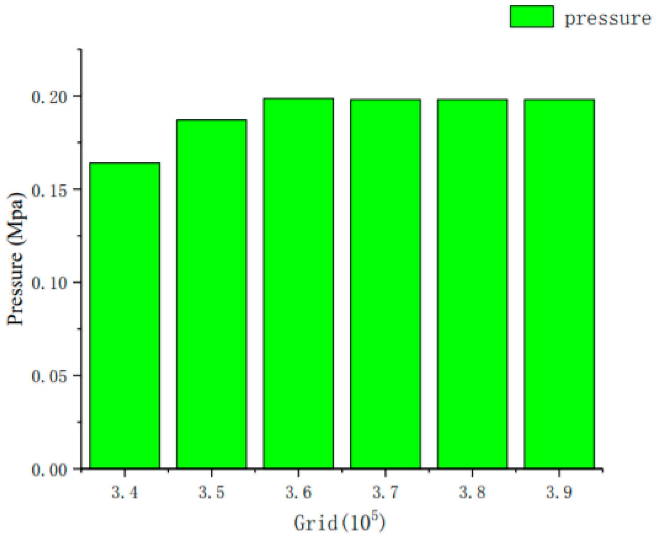
| Grid Number (×105) | Pressure (Mpa) | Velocity (m/s) |
|---|---|---|
| 3.43 | 0.1615 | 6.74 |
| 3.51 | 0.1782 | 6.81 |
| 3.62 | 0.1825 | 6.85 |
| 3.67 | 0.1834 | 6.85 |
| 3.74 | 0.1852 | 6.85 |
| 3.85 | 0.1873 | 6.85 |
| 3.87 | 0.1869 | 6.85 |
| Properties | Rotating Ring | Stationary Ring |
|---|---|---|
| Material | Silicon Carbide | Carbon Graphite |
| Density ρ (kg/m3) | 3150 | 1810 |
| Specific heat capacity c (J/kg·K) | 710 | 880 |
| Thermal conductivity k (W/m·K) | 150 | 45 |
| Thermal expansion coefficient α (1/K) | 4.3 × 10⁻⁶ | 6.2 × 10⁻⁶ |
| Poisson ratio | 0.27 | 0.26 |
| Elastic modulus E (GPa) | 380 | 25 |
| Type | Details |
|---|---|
| Entrance boundary | pressure inlet |
| Exit boundary | pressure outlet |
| Wall boundary | standard wall functions |
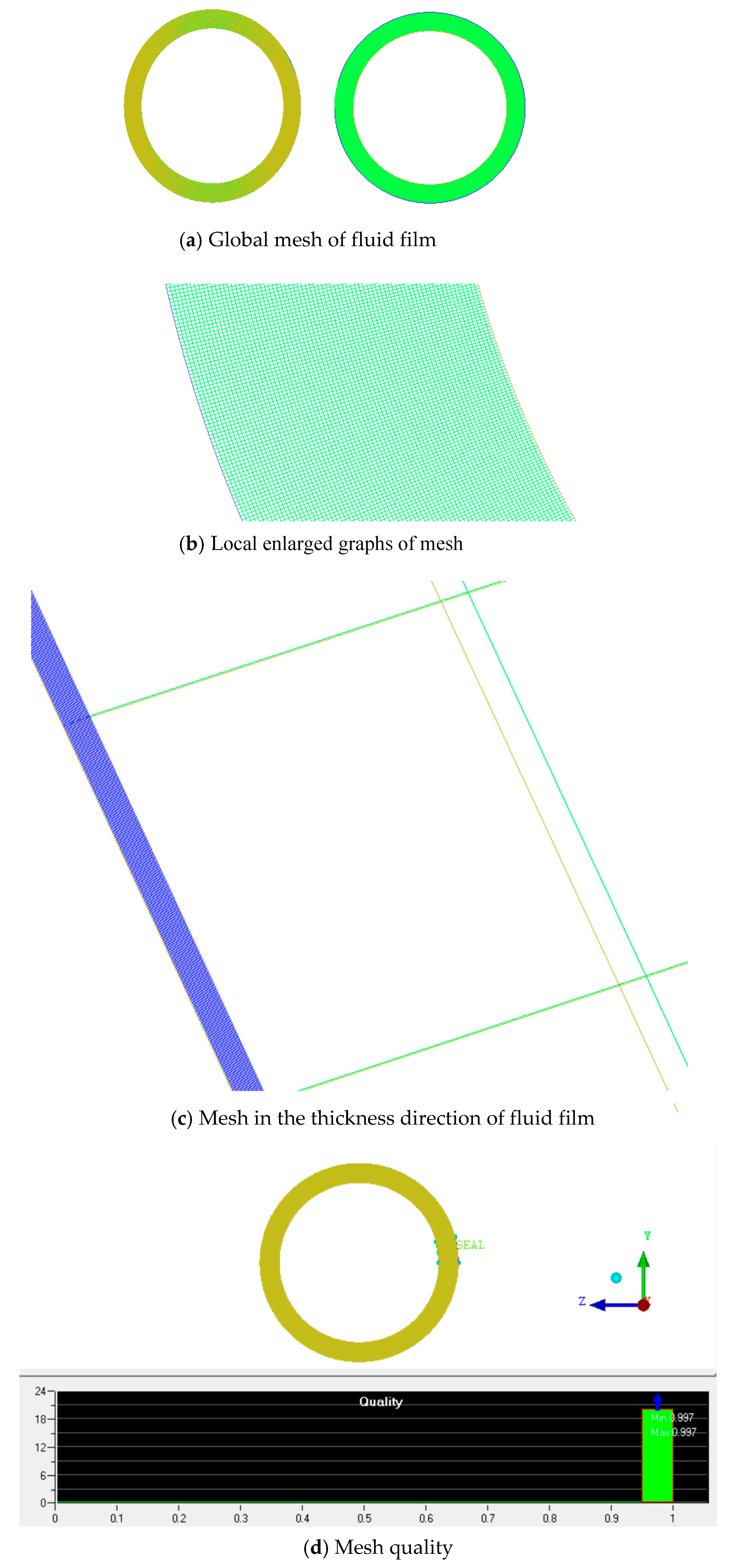
| Mesh quality | 0.9 |
| Grid number | 362,943 |
| Flow state | laminar flow |
| Algorithm | Simple C |
| Solver | Steady-state solver |
© 2020 by the authors. Licensee MDPI, Basel, Switzerland. This article is an open access article distributed under the terms and conditions of the Creative Commons Attribution (CC BY) license (http://creativecommons.org/licenses/by/4.0/).
Share and Cite
Luo, Y.; Fan, Y.; Han, Y.; Zhang, W.; Acheaw, E. Research on the Dynamic Characteristics of Mechanical Seal under Different Extrusion Fault Degrees. Processes 2020, 8, 1057. https://doi.org/10.3390/pr8091057
Luo Y, Fan Y, Han Y, Zhang W, Acheaw E. Research on the Dynamic Characteristics of Mechanical Seal under Different Extrusion Fault Degrees. Processes. 2020; 8(9):1057. https://doi.org/10.3390/pr8091057
Chicago/Turabian StyleLuo, Yin, Yakun Fan, Yuejiang Han, Weqi Zhang, and Emmanuel Acheaw. 2020. "Research on the Dynamic Characteristics of Mechanical Seal under Different Extrusion Fault Degrees" Processes 8, no. 9: 1057. https://doi.org/10.3390/pr8091057
APA StyleLuo, Y., Fan, Y., Han, Y., Zhang, W., & Acheaw, E. (2020). Research on the Dynamic Characteristics of Mechanical Seal under Different Extrusion Fault Degrees. Processes, 8(9), 1057. https://doi.org/10.3390/pr8091057