Article

Numerical Simulations of Molten Breakup Behaviors of a de Laval-Type Nozzle, and the Effects of Atomization Parameters on Particle Size Distribution

1
State Key Laboratory for Advanced Metals and Materials, University of Science and Technology Beijing, Beijing 100083, China
2
Department of Mechanical Engineering, McGill University, Montreal H2A0C3, QC, Canada
3
School of Mechanical Engineering, University of Science and Technology Beijing, Beijing 100083, China
4
Beijing General Research Institute of Mining & Metallurgy Technology Group, Beijing 100160, China
*
Author to whom correspondence should be addressed.
Processes 2020, 8(9), 1027; https://doi.org/10.3390/pr8091027
Submission received: 23 July 2020 / Revised: 13 August 2020 / Accepted: 18 August 2020 / Published: 22 August 2020
(This article belongs to the Section Advanced Digital and Other Processes)

Abstract

:
In this work, an atomizer with a de Laval-type nozzle is designed and studied by commercial computational fluid dynamics (CFD) software, and the secondary breakup process during atomization is simulated by two-way coupling and the discrete particle model (DPM) using the Euler-Lagrange method. The simulation result demonstrates that the gas flow patterns greatly change with the introduction of liquid droplets, which clearly indicates that the mass loading effect is quite significant as a result of the gas-droplet interactions. An hourglass shape of the cloud of disintegrating molten metal particles is observed by using a stochastic tracking model. Finally, this simulation approach is used for the quantitative evaluation of the effects of altering the atomizing process conditions (gas-to-melt ratio, operating pressure P, and operating gas temperature T) and nozzle geometry (protrusion length h, half-taper angle α, and gas slit nozzle diameter D) on the particle size distribution of the powders produced.

1. Introduction

High quality metal powder is the basis for applications such as powder metallurgy, metal injection molding, spray coating, laser cladding, metal welding, and additive manufacturing [1,2,3]. Rising surface and molding technologies demand finer metal powders and a narrow particle size distribution, which has greatly promoted the development of powder production technology. Due to its versatility, quality, and purity, gas atomization is currently considered the best way to produce high quality, spherical metal powders. The basic principle of gas atomization is utilizing the kinetic energy of a high-speed gas jet to breakup liquid molten metal, and the broken droplets are then spheroidized under the surface tension and undergo rapid solidification to obtain spherical metal powders. The gas atomization breakup process involves the complex multiphase coupling between the high-speed gas jet and the high-temperature molten metal stream, which occurs under the conditions of an extremely high cooling rate, momentum exchange, and heat exchange [4]. Although gas atomization has been used to manufacture metal powders for quite a long time, the detailed physics process is still not fully understood.
There is plenty of research about the traditional annular-slit atomizing nozzle, in which the gas exists in an under-expanded state when the it flows through the slit under high pressure. Researchers have established that its structure consists of shear mixing layers, Prandtl-Meyer expansion waves, and closed-wake conditions [5,6]. The repeating, reflecting pattern of the close-coupled nozzle has been studied by J. Ting and I. Anderson, and shows shock-cell, diamond structured gas dynamic behavior [7,8]. The de Laval nozzle atomizer, which has emerged in recent years, is a type of de Laval annular slit combined with a close-coupled atomizer. The gas flow field is different from the traditional annular slit atomizer due to the construction of the de Laval-type annular gas slit. We obtained a fully-expanded gas jet with no Mach disk, and the shock expanded wave was acquired after the outer flow field [9,10].
Typically, the breakup process during atomization can be divided into two stages. In the primary breakup stage, the surface of the molten melt shows disturbance caused by a high-velocity gas jet, and is broken up into unstable ligaments and large-sized droplets [11,12]. Before solidification, the size of the ligaments and large droplets is greatly reduced. They transform into fine droplets in the secondary breakup stage, which will ultimately determine the particle size distribution of the metal powders [13]. Therefore, research on the secondary breakup process is indispensable. Based on the Weber number theory, Zeoli et al. [14] simulated the secondary breakup process of metal melt using a combination of the Kelvin-Helmholtz (KH) instability model and the Taylor analogy breakup (TAB). They distinguish the breakup model with the Weber number, and help in improving the model prediction of the secondary breakup process. Firmansyah et al. [15] used the two-way coupling between the gas and droplets to demonstrate the effect of the droplets on the flow field pattern change via the Euler-Lagrange configuration. G.S.E Antipas [12,16] presented an integrated model called “surface wave formation” for the primary and secondary atomization of a liquid column that demonstrates the ability to assess the spatial distribution of particles inside a two-phase turbulent spray. J.S. Thompson [17] evaluated two different secondary breakup models, including the KH-TAB model utilized by Zeoli [14] and the Kelvin-Helmholtz Rayleigh-Transport (KHRT) model, by using the particle size data from the business company to identify the accuracy of the model. Thompson found that the KHRT model is more accurate and robust for the simulation of the secondary breakup process. Moreover, the lattice Boltzmann simulations of drop deformation and breakup was applied to the gas atomization process by Komrakova et al. [18]. However, all these works are based on the annular slit nozzle; research that utilizes the de Laval-type nozzle is basically nonexistent. Therefore, it is vital to study the gas flow characteristics and breakup mechanism using a de Laval-type nozzle.
In this paper, an annular de Laval-type slit gas atomizer was designed for the numerical simulation of the atomizing process. Subsequently, we simulated the breakup of secondary droplets, and tracked the motion of the droplets within the flow field using the KHRT model. We improved the accuracy of the model by entering dynamic thermo-physical properties, which can quantitatively assess the effects of the process parameters on the particle size distribution. Additionally, we intend to improve the gas flow field structures and optimize the structural parameters of the model via numerical simulation.

2. Model Description

2.1. Design of de Laval-Type Atomizer

The de Laval nozzle, also called the converging–diverging nozzle, primarily consists of a convergent section, a divergent section, and the “throat,” where the cross-sectional area is at its minimum. During the atomizing, the gas jet in the de Laval nozzle is under a state of isentropic flow, which conforms to the isentropic flow equation [19]. It is assumed that any cross-sectional area in the de Laval curve is A, and the minimum critical area is A0. For the de Laval nozzle, the gas jet Mach number Ma and area ratio A/A0 have the relationship given by Equation (1) [20]:
A A 0 = 1 M a [ ( 1 + k 1 2 M a 2 ) 2 k + 1 ] k + 1 2 ( k 1 )
where Ma is the gas jet Mach number, the specific heat ratio k for the nitrogen is k = 1.4, and A/A0 varies with the Mach number, as shown in Figure 1. It can be observed from Figure 1 that when the area ratio A/A0 is determined, the Mach number follows. Additionally, the same area ratio A/A0 corresponds to two Mach numbers, which respectively correspond to the subsonic flow (Ma < 1) and the supersonic flow (Ma > 1) states in the de Laval tube.
The convergent wall curve in the de Laval nozzle is generally determined by the Witoszynski Curve Method, the Batchelor-Shaw Curve Method, or the High-order Curve Method [21,22,23,24]. The divergent wall curve is mainly determined by the Characteristic Method or the Foelsch Method [25].
In this paper, as shown in Figure 2, the convergent section curve AB is determined by the High-order Curve Method, and two methods are used for the diverging section (BC and CD), which includes the Characteristic Method. The specific curve equations are as follows.
Convergent section curve AB:
R R 0 R 1 R 0 = 1 10 ( x L 1 ) 3 + 15 ( x L 1 ) 4 6 ( x L 1 ) 5
where R0 is the de Laval throat radius, R1 is the gas inlet radius, L1 is the total length of the convergent section, x is the coordinate of the x-axis in Figure 2, and R is the transition arc radius corresponding to the x position.
Divergent section curve BC and CD: Using the Characteristic Method to obtain the line equation and connect it smoothly.
B C : y = r 1 + R 0 r 1 2 x 2 , 0 x x c C D : y = R 2 + r 2 + r 2 2 ( x L 2 ) 2 , x c x L 2 C : ( r 1 s i n θ ,   R 0 + r 1 ( 1 c o s θ ) )
where L2 is the total length of the divergent section, θ is the divergent angle, r1 and r2 are the radius of the analytical circle, and R2 is the gas outlet radius. In this paper, in order to obtain a higher gas velocity at the lower atomizing pressure, the designed Ma = 4.04, and the corresponding A2/A0 = 11.56, R0 = 0.3 mm, R1 = 3.2 mm, R2 = 1.02 mm, r1 = 15.0 mm, r2 = 14. 3 mm, L1 = 8.0 mm, L2 = 6.67 mm, and θ = 25°.
From the above content, we confirmed the parameters of the de Laval-type gas slit. Typically, the structure of the atomizing nozzle depends on the half-taper angle α, the gas injection ring diameter D, and the protrusion length of the melt delivery tube h. These critical parameters will greatly affect the gas flow field structure and the metal melt breakup process during atomization [26].

2.2. Modelling the Fluids

The gas flow field in atomization process can be described by k-ε, k-ɷ, and the Reynolds Averaging Naiver–Stokes (RANS). The turbulent gas flow behavior can be properly described by the k-ε model with less simulation, so we chose it as the turbulence model of the gas flow field [27].
To simulate the secondary breakup process of the droplets, the discrete particle model (DPM) is implemented in ANSYS Fluent, and the Euler–Lagrange approach is utilized to describe the melt breakup behavior. We assume that the metal melt stream becomes an ensemble of large droplets after the primary breakup, and further transforms into fine droplets after the secondary breakup process. The motion and trajectories of the particle droplets can be predicted by force balance, which equates the particle’s inertia with the forces that act upon it. The equation is written in the Lagrange reference frame [28]:
d u p , i d t = u i u p , i t r + g i ( ρ p ρ g ) ρ p + F i  
Here, ( u i u p , i ) / t r is the drag force per unit particle mass, and the Fi term includes the incorporation of additional forces. t r is the droplet relaxation time, defined as
t r = 24 C d R e d p 2 ρ p 18 μ
The droplet relative Reynolds number Re is defined as
R e = ρ p d p | u p , i u i | μ
In Equations (4)–(6), the index i represents the three coordinates of the particle position and velocity components, ui and up,i refers to the particle velocity, respectively; μ is the molecular viscosity of the gas, ρg and ρp represents the density of the gas and particle, respectively; Fi refers to the incorporation of additional acceleration, dp is the particle diameter, and the Cd is the drag coefficient [17,28].
The process of secondary breakup can be described by four breakup models: the TAB model, the WAVE model, the Stochastic Secondary Droplet (SSD) model, and the KHRT model. The TAB model is based on Taylor’s analogy [29] between an oscillating and distorting droplet and a spring mass system. The WAVE model considers the breakup of the droplets to be induced by the relative velocity between the gas and liquid phases. It assumes that the time of breakup and the resulting droplet size are related to the fastest-growing Kelvin-Helmholtz (KH) instability [30]. The SSD model [31] treats breakup as a discrete random event that results in a distribution of diameter scales over a range. The KHRT model combines the effects of the Kelvin–Helmholtz model with the Rayleigh–Taylor (RT) instabilities. It assumes that there is a liquid core near the nozzle area, and the liquid core droplets are suddenly accelerated when they are ejected into the freestream, and RT instability becomes the main influence. From the Levich theory [32], we can obtain the length of the liquid core
L = C l d 0 ρ l ρ g
where Cl is the Levich constant and d0 is a reference nozzle diameter specified for atomizer injections in Fluent.
The KH model is based on linear stability analysis of a liquid jet, with its fastest growing mode contributing to the eventual breakup and generation of new droplets. The wave length of the fastest growing mode and growth rate was found numerically to be [33]
λ K H = 9.02 R ( 1 + 0.45 Z 0.5 ) ( 1 + 0.47 T 0.7 ) ( 1 + 0.87 W e g 1.67 ) 0.6
ω K H = ( 0.34 + 0.38 W e g 1.5 ) ( 1 + Z ) ( 1 + 1.4 T 0.6 ) ( σ ρ l R 3 ) 3
where λ K H is the wave length of the KH wave, ω K H is its growth rate, R is the jet radius, σ is the surface tension of the melt, Z is the Ohnesorge number, defined as
Z = W e l 0.5 R e l
and T is the Taylor number, defined as
T = Z W e g
The relationship between the radius of the new droplet r generated in the primary breakup process and the wave length λ K H is described below
r = B K H λ K H
where BKH is the size constant of the KH breakup model. The KH breakup time scale tKH is computed by
t K H = 3.726 C K H r λ K H ω K H
where CKH is the time constant of the KH breakup, which is a value between 1.732 and 20 [28].
Like the Kelvin-Helmholtz model, the RT model is founded on wave instabilities on the surface of the droplet. The frequency of the fastest growing wave is calculated as
ω R T = 2 ( g t ( ρ l ρ g ) ) 3 / 2 3 3 σ ( ρ l + ρ g )
where gt is the droplet acceleration in the direction of motion. The corresponding wave number is given by
K R T = g t ( ρ l ρ g ) 3 σ
Breakup occurs after RT waves have been growing for a longer time than the breakup time t R T , defined as
t R T = C t ω R T
where C t is the Rayleigh–Taylor breakup time constant, which has a default value of 0.5 [28].
When the tracked wave length 2 π C R T / K R T is smaller than the local droplet diameter. The radius of the smaller child droplets is calculated as follows
r c = π C R T K R T
where C R T is the breakup radius constant, which has a default value of 0.1 [28].
The KHRT effects are calculated and considered for breakup outside the liquid core. Within the liquid core, only aerodynamic breakup computed by the WAVE breakup model is considered. Normally, the RT instability grows faster when droplet acceleration is high, and this effect is dominant for a high Weber number stream [28].

2.3. Model Implementation

Due to the symmetry of the atomizer model, a 2D axis-symmetric computational domain is performed on one half of the axial section of the atomizer chamber with a 200 mm length and 80 mm width, and the boundary conditions are illustrated in Figure 3.
To evaluate the droplet particle size distribution produced by the secondary breakup, a transient two-way turbulence coupling Euler-Lagrange method was utilized. The dispersion of the particles can be expressed by the stochastic tracking model with the discrete random walk model. To ensure solution convergence and capture the molten melt breakup process, very small time steps of 1 × 10⁻⁷ s were employed in this simulation. Nitrogen was selected as a compressible atomizing gas. The density was set to “ideal gas”, and the viscosity was calculated by the Sutherland law. Other properties were taken from the Fluent database. A Fe-based self-fluxing alloy (FeNiCrBSiNbC) was selected as a molten metal material, where the obtained powder was used for laser cladding. To approximate the manufacturing process of the metal powders, this simulation utilized dynamic thermo-physical properties, as shown in Figure 4. The initial diameters of the inner parent droplets were set to 0.4~4.0 mm with a Rosin-Rammler distribution, and the droplets were injected at the top corner of the melt nozzle at a temperature of 1890 K (200 K superheat) with a mass flow rate of 0.1 kg/s, corresponding to a gas-to-melt ratio (GMR) of 3.09. The de Laval-type nozzle operated at a pressure of 2.0 MPa and temperature of 300 K during the entire simulation process unless otherwise noted.
Considering the potential influence of mesh size, we assumed a maximum generic mesh spacing of δ. Mesh spacings in the range of 1/2δ, 3/5δ, 2/3δ, and 4/5δ were produced to verify the independence of the mesh space in the simulation. The d50 value after a sufficient number of iteration steps was used to evaluate the influence of the mesh space, and it was observed that the d50 difference between the coarse mesh spacing of 4/5δ and the finest mesh spacing of 1/2δ was well below the 2% error, as can be seen in Figure 5. Therefore, the structured grid has a cell number of 155,048, with the mesh space of 3/5δ selected due to the considerations of the simulation amount and accuracy. Figure 6 plots the influence of simulation time on the average diameter of the droplets in different mass flow rates. It was determined that a simulation time of approximately 5.0 ms was required to reach a stable d50 value; beyond that, there is no substantial change in the particle size distribution, indicating that the system reached a steady-state condition.

3. Results

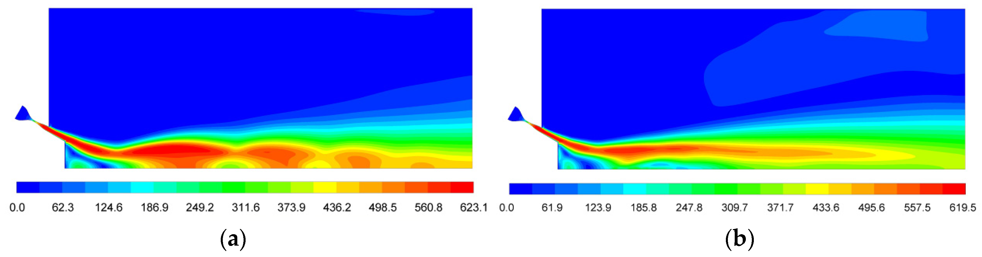
3.1. Flow Field Analysis

The de Laval nozzle will show different working modes under different pressures. Therefore, it will affect the particle size distribution of the droplets after breakup. The structure of the flow field was first studied before the melt was injected. Figure 7 presents the velocity contours developed in the region adjacent to the nozzle exit of the atomizing jet. The typical flow field of a nozzle slit is an under-expanded jet flow, a clear Mach disk, and a closed-wake structure [14]. Unlike the typical nozzle slit, the atomizing gas can be fully expanded in the de Laval nozzle due to its special convergence–divergence structure. The gas is constantly accelerating and reaches the speed of sound in the throat area, and then reaches supersonic speed in the divergence area. Therefore, parallel supersonic gas jets can be obtained in the nozzle exit. The maximum gas velocity that can be reached is 623 m/s, and the supersonic gas jets then meet and reflect below the delivery tube to form a series of periodic diamond-shaped reflected waves.
Figure 8 shows the influence of the particle droplets on the gas flow field. From the contours, we can see that the gas velocity on the central axis is significantly decreased due to the breakup effect and the mass loading effect. Additionally, the kinetic energy of the gas jets has dropped dramatically, and the maximum velocity on the central axis is reduced by almost 40%. When comparing the gas flow field with the two-way coupling, significant changes can be observed in the behavior of the atomizing jets, especially under the recirculation zone; the droplets converged in this area and destroyed the stability of the velocity field, which resulted in the velocity become disrupted and the disappearance of the periodic diamond-shock reflected waves. These findings show the importance of utilizing two-way coupling when simulating the gas atomizer with a realistic heavy particle loading [17].

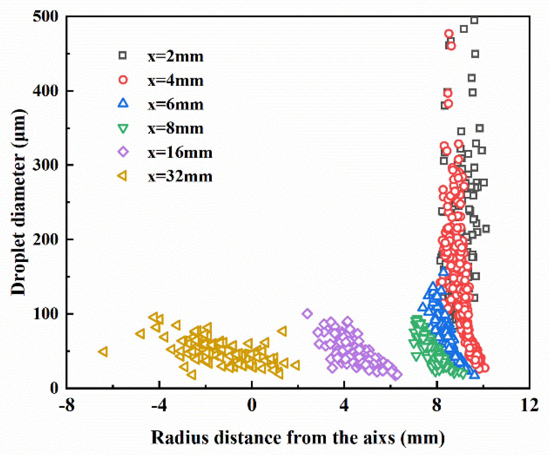
3.2. Breakup Behavior

According to the research of Mates and Settles [5], the particle size of the atomized powder is mainly determined by the secondary breakup process and the primary breakup in large ligaments (dligaments/djet = 0.1~1 [34]). Therefore, the initial diameters of the inner parent droplets were set to 0.4~4.0 mm and the droplets were injected at the top corner of the melt nozzle. In this model, when the melt temperature is lower than the melting point of 1520 K, it is considered solidified and no more breakup occurs.
Figure 9 shows the trajectories of the particle droplets produced by the KHRT models. The parent droplets breakup and are accelerated by supersonic gas jets, which produce a comet-like cloud of disintegrating molten metal droplets. As shown in Figure 9a, the velocities reach almost 200 m/s after acceleration, and some even reach 300 m/s. The size of the particles represents the diameter of the droplets and the color represents the speed in Figure 10. The droplets have a significant breakup effect between the recirculation zone and the high-speed jet interface, resulting in a large number of small droplets. These small droplets are accelerated by the high speed gas flow, and, converging below the recirculation zone, the broken small droplets accelerate to more than 143.3 m/s (corresponding to the yellow droplets), while the large droplets with insufficient breakup have a speed of 46.0~98.1 m/s (corresponding to the green droplets). The colors in Figure 9b represent different sizes of droplets. The red parent droplets undergo a fast breakup process after being released near the nozzle, which turns the red droplets (~1 mm) to yellow (~70 μm) and blue (~50 µm) within a short distance of 50 mm from the tube. From Figure 9c and Figure 10, we can see that in this region, where the droplet size changes drastically, the temperature of the droplets decreases relatively slowly near the nozzle exit area. However, after the violent breakup, the temperature of the child droplets decreases more sharply because the small particle size results in a large specific surface area and a faster heat transfer rate, which will increase the cooling rate [35,36]. However, in the downstream region, the color map of the diameters of the droplets shows that the diameters remain stable, indicating that the droplets are no longer substantially broken up in this region.
The particle diameter and temperature data for the particle trajectories extracted from Fluent is presented in Figure 11. Due to the Rosin-Rammler distribution of the initial parent droplets, in a short period of 0.5 ms, the diameters of the droplets were spread over a wide range of 20~2000 μm, and their temperatures remained high. After that, the particle size sharply reduced to 20~100 μm because of the breakup effect, and this was accompanied by a dramatic decrease in temperature. Finally, most of the child droplets flew away from the simulation area in 2 ms. To demonstrate the detailed change of the diameters of the droplets, we sampled droplets at different axial positions as a function of the radial distance from the nozzle axis (Figure 12). x represents the distance between the droplets and the delivery tube, and from this we found that the diameters of the droplets at x = 2 mm vary significantly from 150~2000 μm, which means that only a few droplets had broken. At x = 4 mm, parent droplets appear together with small-sized child droplets, and increasingly more droplets breakup in this region. At x = 6~8 mm, the particle size decreased sharply to 20~200 μm, which is attributable to the very high gradient of the velocity between the gas and droplets; the RT instability increases faster and dominates the main breakup process. When x > 8 mm, the vertical distance of the droplets is gradually decreased to a negative value, and the diameter remains in the range of 20~100 μm, indicating that the droplets travel through the axis, and there is essentially no more breakup in the downstream area. In order to quantitatively evaluate the diameter reduction of the droplets during the atomizing process, we sampled droplets at the exit boundary and extracted their sizes. Detailed analysis is provided in the next section.

4. Effect of Atomizing Parameters

The KHRT breakup model was used to extract the droplet sizes after the breakup process to assess the effects of the gas-to-melt mass flow ratio (GMR), operating pressure P, operating temperature T, half-taper angle α, protrusion length h, and gas slit nozzle diameter D. The statistical distribution of the droplets obtained from the model exit region will obtain the d50, d84/d50 and SPAN = (d90 − d10)/d50 of the droplets to evaluate the breakup effect of different parameters.

4.1. Effect of GMR

The gas-to-melt mass flow ratio describes the gas energy input during atomization. It is a measure of the economic efficiency of the atomization equipment [36]. Utilizing the predictive ability of the model, the effect of GMR on d50 was assessed. Figure 13 shows the particle size distribution and cumulative mass fraction at a melt mass flow rate of 0.16 kg/s. Like the atomized powders, the simulation data presents a typical normal distribution. To demonstrate the effect of GMR on particle size distribution, we further sampled the d50, then calculated the values of d84/d50 and SPAN at different GMRs. As shown in Figure 14, the d84/d50 refers to the standard deviation, SPAN = (d90 − d10)/d50, and is used as a measure of the width of the particle size distribution. From this, we can see that a smaller melt mass flow rate resulted in smaller values of d50, d84/d50 and SPAN. This is expected, higher GMR means that more gas jet energy input interacts with the same melt. This will obviously decrease the particle mean diameter and create a narrower spread of the distribution.

4.2. Effect of Operating Pressure

Figure 15 illustrates the effect of operating pressure on the d50 process data and measure of standard deviation. As we can see in this simulation, with the increase of the operating pressure from 1.2 MPa to 2.7 MPa, the median diameter and standard deviation decrease significantly. This means that increasing the atomization pressure not only helps to obtain a fine powder, but also decreases the spread of the particle sizes. However, when the atomization pressure is increased to ~3 MPa, the median diameter and standard deviation start to maintain stability, a phenomenon that has also been observed in actual experiments [37]. Although high pressure promotes the full breakup of droplets, collision and fusion among broken droplets become stronger, which forms larger-sized particles and satellite powders; therefore, fine powder exhibits little change at a high gas pressure. Essentially, increasing the operating pressure has the same effects on particle size distribution as does the large GMR; they both enlarge the gas energy input during atomization.

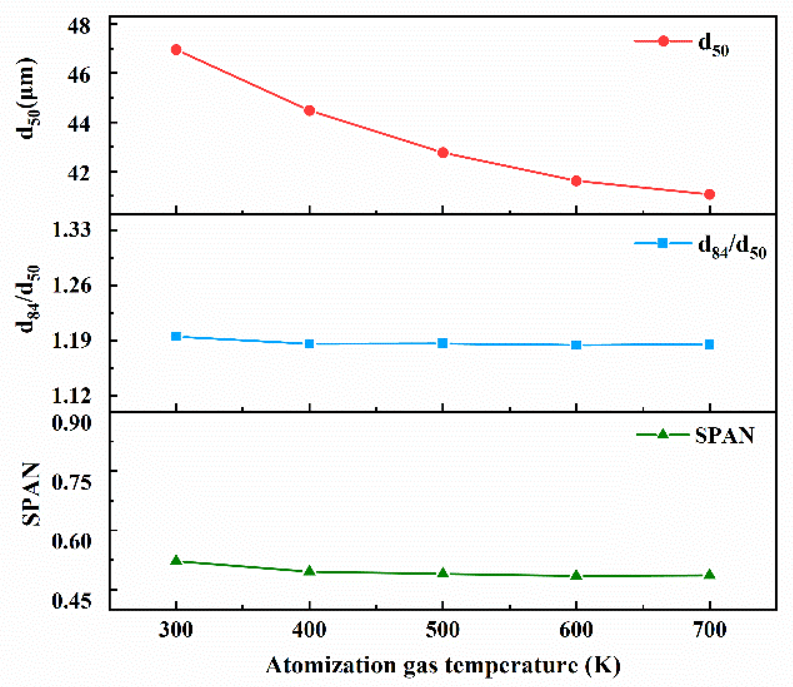
4.3. Effect of Operating Gas Temperature

Figure 16 represents the relationship of the operating gas temperature with the d50 process data and the measure of standard deviation. A similar trend can be identified for increases in both the operating pressure and operating temperature. High-temperature gas brings about the formation of finer particles as compared to a cold gas temperature due to higher kinetic energy, and therefore contributes to a greater gas velocity. However, the standard deviation and SPAN exhibits no obvious change in different gas temperatures. From the data, it is evident that the standard deviation values fluctuate around 1.2, which is significantly lower than the standard deviation of classical atomized powder (usually 2.0) [36].

4.4. Effect of the Half-Taper Angle

The half-taper angle α is the gas nozzle convergent angle towards the centerline. Figure 17 shows the effect of the half-taper angle on the d50 process data and the measure of standard deviation. From the simulation results, we know that with the increase of the half-taper angle, the d50 exhibits a linearly decreasing trend, and that a larger half-taper angle is beneficial for obtaining finer powders. However, the standard deviation and SPAN did not follow this reduction. Previous research has revealed that a larger half-taper angle also leads to a severe aspiration pressure turbulence of the recirculation zone, which may block the outflow of the molten metal melt [10].

4.5. Effect of Protrusion Length

Figure 18 shows the influence of the melt tube protrusion length on the normalized D50 and standard deviation. We can clearly determine the effect of the protrusion length on the particle size distribution. When the protrusion length of the melt tube is 4~10 mm, with the increase of the protrusion length, the d50 exhibits a tendency of unilateral decline, and the standard deviation and SPAN remains steady. However, when the protrusion length of the melt tube is 12 mm, both the d50 and standard deviation increase sharply. From the results of the atomization flow field simulation study, we can obtain a lower aspiration pressure when the melt tube protrusion length is in the range of 6~10 mm.

4.6. Effect of the Gas Slit Nozzle Diameter

The gas slit nozzle diameter refers to the diameter of the gas jet out of the nozzle exit. Figure 19 shows the influence of the gas slit nozzle diameter on the normalized d50 and standard deviation. In this research, gas slit nozzle diameters of 26.8 mm to 50.8 mm at intervals of 6 mm were simulated. It can be seen that as the gas slit nozzle diameter increases, so does the standard deviation and SPAN. However, the d50 value is reduced continuously as the gas slit nozzle diameter increases. This means that a larger gas slit nozzle diameter can result in finer powders, but a wider size range. However, it will also increase the flight distance of the gas, which can cause a reduction of gas kinetic energy.

5. Discussion

According to the above analysis, it is evident that the two-way coupling between melt droplets and gas flow has a huge impact on the gas flow field during the atomization breakup process; periodic reflected waves were replaced by a ring-wrapped gas flow. In the range of x = 4~8 mm, near the nozzle top corner where the RT instability dominates the breakup behavior, the released parent droplets will be broken up in a short period time (0.5 ms). The broken droplets then flow downstream with the gas flow to form an hourglass molten droplet cloud, and most of the child droplets fly away from the simulation area in 2 ms.
We then explored the effects of the atomizing process conditions and nozzle geometry parameter on the particle size distribution for the KHRT model. Generally speaking, we intended to obtain finer particles and a concentrated particle size distribution with a low standard deviation in an industrial manufacturing process. For the atomization structure parameters, the above numerical simulation data suggest that a larger half-taper angle α results in finer metal powders. However, gas flow field research shows that it also increased the aspiration pressure in the recirculation zone, which would block the outflow of the metal melt. Therefore, it is more appropriate to use the median value of 30°. The protrusion length range of 8~10 mm of the delivery tube h was found to be better for obtaining finer powders. Additionally, although increasing the gas slit nozzle diameter D can reduce the average particle size, it will also simultaneously increase the standard deviation and enlarge the gas flow field; therefore, we tend to choose a smaller gas slit nozzle diameter, such as 32.8 mm. For the operating parameter, although increasing the operating gas temperature can effectively reduce the average particle size, it demands complex extra equipment and costs a significant amount of energy in industrial production. Therefore, it must be determined according to the actual situation. We also examined the influence of atomizing conditions on the particle size distribution, which can provide an effective basis for parameter selection in industrial production. Typically, as powder must be supplied with tailored distributions to meet the requirements of its intended use (e.g., laser cladding demands an average particle size in the range of 80~95 μm), it is essential to minimize this off-size powder inventory to ensure a powder producer remains competitive. Therefore, we can roughly determine the range of operating pressure to be 2 MPa and the melt mass flow rate to be 0.6 kg/s by the simulation of the operating conditions.
This work provides a method to design a de Laval-type gas nozzle atomizer. The specified FeNiCrBSiNbC alloy secondary breakup process was simulated by the validated KHRT model. Research on the atomization structural parameters and atomizing conditions can be used for the design of the atomizing nozzles and for optimizing their parameter selection in industrial production. In addition, it will contribute to the understanding of the principle of the secondary breakup process in the de Laval-type nozzle. However, many problems remain to be solved, such as improving the reliability of the model and studying the entire process of atomization, rather than dividing it into primary and secondary breakup processes. At the same time, the predictive capability of the KHRT model need be proven by experiments, which is our main task in future work.

6. Conclusions

A de Laval-type gas outlet atomizer was designed and studied using CFD software. To assess the interaction between the gas jet and molten metal, we used the Euler–Lagrange method to describe the gas flow field and metal droplets. The validated KHRT model was used for the quantitative assessment of the particle size distribution. From this simulation, we can see that an hourglass cloud of child droplets was generated; a far more realistic particle track than Zeoli [14] was produced by this breakup model. The characteristics of the flow field with the particle load demonstrate that the two-way coupling was vital for approximating the impact of the particles on the behavior of the fluid flow. This simulation approach was used for the quantitative evaluation of the effects of altering the atomizing process condition and nozzle geometry on the particle size distribution of the produced powders. From this study, we have drawn the following conclusions:
  • A higher GMR results in a decrease in d50 and standard deviation.
  • At relatively low pressures, increasing the operating pressure results in a decrease in particle size and reduces the standard deviation. However, the increase will become invalid at high pressures.
  • Increasing the operating gas temperature and the half-taper angle leads to a decrease in d50, but the standard deviation remains stable. Additionally, a half-taper angle of 30° is more suitable for the de Laval-type atomization nozzle.
  • Increasing the protrusion length within a certain range leads to a decrease in particle size, which increases suddenly when the protrusion length is increased to 12 mm.
  • When the gas slit nozzle diameter is increased, the d50 value exhibits a decreasing trend. However, it also causes a wider spread of the particle size distribution. For the consideration of tight coupling, we intend to choose a relatively small diameter, e.g., 32.8 mm in atomization.

Author Contributions

L.X.; Molten Breakup Analysis, Calculation and Simulation and Writing-Original Draft Preparation, X.Z.; Research Plan, Methodology and Project Administration, J.L. Analysis of Atomization Process and Article Structure, Y.H., H.Q. and W.W.; Software and Assistance in Research; K.D. and Y.M.; Analysis of Atomization Process and Molten Breakup, Y.Y.; Supervision and Project Administration. All authors have read and agreed to the published version of the manuscript.

Funding

This research was supported by the National Key Research and Development Program of China (Grant No. 2017YFB0306102) and the National Natural Science Foundation of China (Grant No. 51271034).

Conflicts of Interest

The authors declare no conflict of interest.

References

  1. Attar, H.; Prashanth, K.G.; Chaubey, A.K.; Calin, M.; Zhang, L.C.; Scudino, S.; Eckert, J. Comparison of wear properties of commercially pure titanium prepared by selective laser melting and casting processes. Mater. Lett. 2015, 142, 38–41. [Google Scholar] [CrossRef]
  2. Antipas, G.S.E. Review of gas atomisation and spray forming phenomenology. Powder Metall. 2013, 56, 317–330. [Google Scholar] [CrossRef]
  3. Sabard, A.; de Lovelock, H.L.; Hussain, T. Microstructural Evolution in Solution Heat Treatment of Gas-Atomized Al Alloy (7075) Powder for Cold Spray. J. Therm. Spray Technol. 2017, 27, 145–158. [Google Scholar] [CrossRef] [Green Version]
  4. Song, C.; Li, K.; Xie, K.; Lu, W.; Zhao, S.; Han, Q.; Zhai, Q. The effect of the nucleation ability on solidified microstructures of gas-atomized Fe–6.5wt.%Si alloy powder. Powder Technol. 2014, 263, 31–36. [Google Scholar] [CrossRef]
  5. Mates, S.P.; Settles, G.S. A Study of Liquid Metal Atomization Using Close-Coupled Nozzles, Part 1: Gas Dynamic Behavior. At. Sprays 2005, 15, 19–40. [Google Scholar] [CrossRef]
  6. Motaman, S.; Mullis, A.M.; Cochrane, R.F.; Borman, D.J. Numerical and Experimental Investigations of the Effect of Melt Delivery Nozzle Design on the Open-to Closed-Wake Transition in Closed-Coupled Gas Atomization. Metall. Mater. Trans. B 2015, 46, 1990–2004. [Google Scholar] [CrossRef] [Green Version]
  7. Ting, J.; Perett, M.W.; Eisen, W.B. The effect of wake-closure phenomenon on gas atomization performance. Mater. Sci. Eng. A (Struct. Mater. Prop. Microstruct. Process.) 2002, 326, 110–121. [Google Scholar] [CrossRef]
  8. Zhao, W.; Cao, F.; Ning, Z.; Zhang, G.; Li, Z.; Sun, J. A computational fluid dynamics (CFD) investigation of the flow field and the primary atomization of the close coupled atomizer. Comput. Chem. Eng. 2012, 40, 58–66. [Google Scholar] [CrossRef]
  9. Si, C.R.; Zhang, X.J.; Wang, J.B.; Li, Y.J. Design and evaluation of a Laval-type supersonic atomizer for low-pressure gas atomization of molten metals. Int. J. Miner. Metall. Mater. 2014, 21, 627–635. [Google Scholar] [CrossRef]
  10. Xu, L.H.; Zhou, X.L.; Li, J.H.; Du, K.P.; Ma, Y.; Yu, Y.G. Design of atomizing nozzle and Simulation of its flow field structure. Therm. Spray Technol. 2019, 3, 5–12. [Google Scholar] [CrossRef]
  11. Anderson, I.E.; Rieken, J.; Meyer, J.; Byrd, D.; Heidloff, A. Visualization of Atomization Gas Flow and Melt Break-up Effects in Response to Nozzle Design. Ames Lab. (AMES) Ames IA 2011. [Google Scholar] [CrossRef]
  12. Antipas, G.S.E. Modelling of the break up mechanism in gas atomization of liquid metals. Part I: The surface wave formation model. Comput. Mater. Sci. 2006, 35, 416–422. [Google Scholar] [CrossRef]
  13. Jain, S.S.; Tyagi, N.; Prakash, R.S.; Ravikrishna, R.V.; Tomar, G. Secondary breakup of drops at moderate Weber numbers: Effect of Density ratio and Reynolds number. Int. J. Multiph. Flow 2019, 117, 25–41. [Google Scholar] [CrossRef] [Green Version]
  14. Zeoli, N.; Gu, S. Numerical modelling of droplet break-up for gas atomization. Comput. Mater. Sci. 2006, 38, 282–292. [Google Scholar] [CrossRef]
  15. Firmansyah, D.A.; Kaiser, R.; Zahaf, R.; Coker, Z.; Choi, T.-Y.; Lee, D. Numerical simulations of supersonic gas atomization of liquid metal droplets. Jpn. J. Appl. Phys. 2014, 53, 05HA09. [Google Scholar] [CrossRef]
  16. Antipas, G.S.E. Modelling of the break up mechanism in gas atomization of liquid metals Part II, The gas flow model. Comput. Mater. Sci. 2009, 46, 955–959. [Google Scholar] [CrossRef]
  17. Thompson, J.S.; Hassan, O.; Rolland, S.A.; Sienz, J. The identification of an accurate simulation approach to predict the effect of operational parameters on the particle size distribution (PSD) of powders produced by an industrial close-coupled gas atomizer. Powder Technol. 2016, 291, 75–85. [Google Scholar] [CrossRef] [Green Version]
  18. Komrakova, A.E.; Shardt, O.; Eskin, D.; Derksen, J.J. Lattice Boltzmann simulations of drop deformation and breakup in shear flow. Int. J. Multiph. Flow 2014, 59, 24–43. [Google Scholar] [CrossRef]
  19. Tsuge, N. Existence of Global Solutions for Unsteady Isentropic Gas Flow in a Laval Nozzle. Arch. Ration. Mech. Anal. 2012, 205, 151–193. [Google Scholar] [CrossRef]
  20. Holten, V.; Heiligers, H.; Jaeken, A. Choking phenomena in a vortex flow passing a Laval tube: An analytical treatment. J. Fluids Eng. 2009, 131, 041201. [Google Scholar] [CrossRef]
  21. Man, H.C.; Duan, J.; Yue, T.M. Design and characteristic analysis of supersonic nozzles for high gas pressure laser cutting. J. Mater. Process. Technol. 1997, 63, 217–222. [Google Scholar] [CrossRef]
  22. Mikhail, M.N.; Rainbird, W. Optimum design of wind tunnel contractions. AIAA J. 2013, 17, 471–477. [Google Scholar] [CrossRef]
  23. Morel, T. Comprehensive design of axisymmetric wind tunnel contractions. ASME 10 Trans. 1975, 99, 225–233. [Google Scholar] [CrossRef]
  24. Wolf, T. Design of a variable contraction for a full-scale automotive wind tunnel. J. Wind Eng. Ind. Aerodyn. 1995, 56, 1–21. [Google Scholar] [CrossRef]
  25. Foelsch, K. The analytical design of axially symmetric Laval nozzle for parallel and uniform jet. J. Aeronaut. Sci. 1949, 16, 161–166. [Google Scholar] [CrossRef]
  26. Zhang, L.; Shao, J.; Chen, X. CFD simulation of nozzle characteristics in a gas aggregation cluster source. Vacuum 2016, 129, 105–110. [Google Scholar] [CrossRef]
  27. Versteeg, H.K.; Malalasekera, W. An Introduction to Computational Fluid Dynamics: The Finite Volume Method; Pearson Education: New York, NY, USA, 2007. [Google Scholar]
  28. Fluent, A. Ansys Fluent Theory Guide v15.0; ANSYS, Inc.: Pittsburgh, PA, USA, 2015. [Google Scholar]
  29. Taylor, G.I. The shape and acceleration of a drop in a high speed air stream. Sci. Pap. G I Taylor 1963, 3, 457–464. [Google Scholar]
  30. Turner, M.R.; Sazhin, S.S.; Healey, J.J.; Crua, C.; Martynov, S.B. A breakup model for transient Diesel fuel sprays. Fuel 2012, 97, 288–305. [Google Scholar] [CrossRef] [Green Version]
  31. Apte, S.V.; Gorokhovski, M.; Moin, P. LES of atomizing spray with stochastic modeling of secondary breakup. Int. J. Multiph. Flow 2003, 29, 1503–1522. [Google Scholar] [CrossRef]
  32. Haber, S. Physicochemical hydrodynamics. Int. J. Multiph. Flow 1997, 23, 1004–1005. [Google Scholar] [CrossRef]
  33. Reitz, R.D. Modeling atomization processes in high-pressure vaporizing sprays. At. Spray Technol. 1988, 3, 309–337. [Google Scholar]
  34. Markus, S.; Fritsching, U.; Bauckhage, K. Jet break up of liquid metal in twin fluid atomization. Mater. Sci. Eng. A (Struct. Mater. Prop. Microstruct. Process.) 2002, 326, 122–133. [Google Scholar] [CrossRef]
  35. Si, C.; Tang, X.; Zhang, X.; Wang, J.; Wu, W. Characteristics of 7055Al alloy powders manufactured by gas-solid two-phase atomization: A comparison with gas atomization process. Mater. Des. 2017, 118, 66–74. [Google Scholar] [CrossRef]
  36. Ciftci, N.; Ellendt, N.; Barreto, E.S.; Mädler, L.; Uhlenwinkel, V. Increasing the amorphous yield of {(Fe 0.6 Co 0.4 ) 0.75 B 0.2 Si 0.05} 96 Nb 4 powders by hot gas atomization. Adv. Powder Technol. 2018, 29, 380–385. [Google Scholar] [CrossRef]
  37. Wei, M.; Chen, S.; Liang, J.; Liu, C. Effect of atomization pressure on the breakup of TA15 titanium alloy powder prepared by EIGA method for laser 3D printing. Vacuum 2017, 143, 185–194. [Google Scholar] [CrossRef]
Figure 1. Relationship between the area ratio and Mach number.
Processes 08 01027 g001
Figure 2. De Laval nozzle curve.
Processes 08 01027 g002
Figure 3. Geometry of computational domain and boundary conditions.
Processes 08 01027 g003
Figure 4. Relationship between the physical properties of FeNiCrBSiNbC alloy molten melt and temperature: (a) viscosity and surface tension; (b) density and specific heat.
Processes 08 01027 g004
Figure 5. A plot of the effect of mesh spacing on the average mean diameter.
Processes 08 01027 g005
Figure 6. The time taken to reach a converged normalized average mean diameter when utilizing the KHRT breakup model.
Processes 08 01027 g006
Figure 7. Velocity contour plots of the gas field in the region near the nozzle exit; (a) without particles, (b) with particles.
Processes 08 01027 g007
Figure 8. Axial velocity curves of the gas field with and without particle injection.
Processes 08 01027 g008
Figure 9. The particle trajectories for the particle velocity magnitude; (a) particle velocity, (b) particle diameter, and (c) particle temperature for the KHRT breakup models.
Processes 08 01027 g009
Figure 10. Partial enlarged view of droplet convergence area.
Processes 08 01027 g010
Figure 11. Droplet diameter and temperature distribution history for the KHRT breakup model.
Processes 08 01027 g011
Figure 12. Radial distributions and diameters of droplets at different axial distances from the melt tube end.
Processes 08 01027 g012
Figure 13. The particle size distribution and cumulative mass fraction for the KHRT breakup model simulation.
Processes 08 01027 g013
Figure 14. The effect of the GMR on d50, d84/d50 and SPAN for the KHRT breakup model simulation.
Processes 08 01027 g014
Figure 15. The effect of operating pressure on d50, d84/d50 and SPAN for the KHRT breakup model simulation.
Processes 08 01027 g015
Figure 16. The effect of operating temperature on d50, d84/d50 and SPAN for the KHRT breakup model simulation.
Processes 08 01027 g016
Figure 17. The effect of the half-taper angle on d50, d84/d50 and SPAN for the KHRT breakup model simulation.
Processes 08 01027 g017
Figure 18. The effect of melt tube protrusion length on d50, d84/d50 and SPAN for the KHRT breakup model simulation.
Processes 08 01027 g018
Figure 19. The effect of gas slit nozzle diameter on d50, d84/d50 and SPAN for the KHRT breakup model simulation.
Processes 08 01027 g019

