Article

Viscous Loss Analysis of the Flooded Electro-Hydrostatic Actuator Motor under Laminar and Turbulent Flow States

School of Automation Science and Electrical Engineering, Beihang University, Beijing 100191, China
*
Author to whom correspondence should be addressed.
Processes 2020, 8(8), 975; https://doi.org/10.3390/pr8080975
Submission received: 12 July 2020 / Revised: 4 August 2020 / Accepted: 10 August 2020 / Published: 12 August 2020
(This article belongs to the Section Process Control and Monitoring)

Abstract

:
The electro-hydrostatic actuator (EHA) is one of the most prevalent types of power-by-wire (PBW) actuation systems. With the increase in EHA power density, using the pump’s leakage oil to cool the motor has been gradually adopted to solve the problem of excessive motor temperature. However, the viscous friction loss caused by the liquid viscosity will seriously affect the heat dissipation effect and dynamic performance of the motor. To calculate the motor viscosity loss accurately, a novel calculation method is proposed in this paper. Using the energy gradient theory, the relationship between the fluid flow state and the rotation speed is analyzed. In addition, the lumped parameter model of viscous loss is established by using the conservation of momentum theory and computational fluid dynamics (CFD) simulation. A test rig is designed to test the viscous friction loss for various rotation speeds, and the test results show a good agreement with the theoretical analysis. The present results demonstrate the effectiveness of the lumped parameter model and provide a better calculation method for wet motor viscosity loss calculation.

1. Introduction

With the rapid development of aviation technology, the power-by-wire (PBW) actuation system in which power transfer from the secondary power system to the actuator will gradually replace traditional hydraulic actuation [1,2,3]. The electro-hydrostatic actuator (EHA) is an essential type of PBW actuation, and, has been successfully applied to More Electric Aircraft (MEA). As shown in Figure 1, EHA is a highly integrated system consisting of an actuator, an accumulator, a hydraulic pump, and a Direct Current (DC) motor. The EHA system has significant advantages, such as high-power density, high efficiency, and high reliability [4]. In contrast, the EHA system also faces the serious problem of concentrated “hot spots” [5], especially in high power motor because there is not enough heat sink to absorb the system’s heat. Excessive temperature rise will cause irreversible demagnetization of the permanent magnet, which will affect the safe operation of the motor and reduce the reliability of the entire actuating system [6]. Therefore, the thermal design for the motor in the EHA system becomes increasingly significant.
Forced convection heat transfer and active load sensitive configuration are useful measures to solve thermal problems [7,8], and one of the feasible ways is to use the leakage oil from the hydraulic pump to cool the high-speed motor [9]. The air gap separating the rotor from the stator will be flooded with oil. Hence, the heat generated in the stator and rotor of the motor can be absorbed and taken away. However, it should be noted that the viscous friction that affects the dynamic performance and the cooling effect will generate during the operation. Therefore, it is critical to evaluate the viscous loss accurately for the design of the EHA motor.
Accurately judging the fluid flow state inside the motor air gap is a prerequisite for calculating the viscosity loss of the motor. The fluid in the motor’s air gap can be considered the Taylor–Couette flow, which analyzes the problem of flow between two concentric rotating cylinders [10,11,12,13]. It observed that the viscous loss would increase rapidly with the rotation speed of the rotor exceeding a critical value, and the flow station transition from laminar flow to turbulent flow is a fundamental factor. Andereck [14] et al. obtained a clear distribution map of the partial flow patterns in the Taylor–Couette system by using equipment in which the rotation speed of the inner and outer cylinders can be changed. Through the study of Andereck et al., the flow situation in the annular gap was clearly defined. Marcus [15] studied the wave-like Taylor vortex in the annular gap without axial flow and obtained the distribution of the fluid velocity field in the annular gap. The Taylor number (Ta) is a vital evaluation index for judging the Taylor fluid flow state [16]. It describes the ratio of the centrifugal force of a flood to its viscous force due to rotation around a fixed axis. The critical value of the Ta was obtained as 3400 by linear analysis and was proven to be valid [16]. However, the criterion using the critical Taylor number did not consider the influence of the curvature of concentric cylinders, and it does not apply to when the gap width to the radius of the rotor tends to zero [17]. The calculated critical rotation speed value based on the Taylor criterion is much larger than the actual critical value. Therefore, a suitable method to judge the fluid flow state in the air gap of the EHA motor should be adopted since the air gap width of high-speed motors is about 0.1 mm to 0.5 mm.
In addition, theoretical and experimental studies have been carried out to investigate the viscous loss of the motor. PS Sangha et al. analyzed the viscous loss of the motor at different temperatures by using a laminar viscous loss theoretical model, and the results were well verified by computational fluid dynamics (CFD) simulation and measurement with a dummy motor, except in high rotation speeds [18]. Qi Wenjuan et al. analyzed the relationship between the viscous loss and the rotation speeds by using the CFD simulation and proposed that the viscous loss model under laminar flow was not applicable to the high rotation speeds state [19], while the viscous loss model in high rotation speeds was not given. J. Saari made a comprehensive analysis of the viscous loss of the motor, and the theoretical formulas for calculating the viscous loss under different flow conditions were proposed [20]. The dimensionless parameters in the equations were difficult to determine, and the criteria for judging the transition of oil flow state were not analyzed. Based on the Taylor number judgment criterion, Wendt [21] fitted the expression of viscosity loss under turbulent flow through a large amount of experimental data, which were based on pure water and water–glycerol mixtures. Yamada [22] also tested the viscous loss between concentric cylinders filled with water and spindle oil and obtained the expression according to the experimental data, but it was very different from the expression given by Wendt [21]. Through the above analysis, there is no unified and comprehensive analysis of the viscous loss of the motor. Therefore, it is essential to calculate the viscous loss according to different flow states as the motor rotation speeds continuously increase.
The study aims to investigate if one can calculate the viscous loss of a flooded EHA motor by analytical equations. The energy gradient theory, which is more suitable for a small air gap, was adopted to judge the flow state, and the specific judgment criteria were analyzed. Besides, a more general viscous loss model under turbulent flow was obtained based on the conservation of momentum theory, and CFD simulation technology was used to determine the size of the relevant parameters in the model, which will greatly reduce the computational cost. The results of this work will contribute to a more comprehensive loss model and targeted support for the optimum design of the EHA motor.

2. Method for Judging Cooling Fluid Flow State

The Taylor number (Ta) is an important evaluation index for judging the Taylor fluid flow state [16]. It describes the ratio of the centrifugal force of a flood to its viscous force due to rotation around a fixed axis and can be expressed as:
T a = R e 2 ( h / R 0 )
where h = R s R r is the air gap width (m), R 0 = ( R s + R r ) / 2 is the mean radius of the stator and rotor (m), R r is the radius of the rotor (m), R s is the radius of the stator (m), Re is the Reynolds number which can be written as:
R e = ω r R r h ν
where ω r is the rotation speed of the rotor (rad/s), ν is the kinematic viscosity (m2/s).
However, as mentioned earlier, the Taylor criterion does not apply to situations where the air gap width is very small. To obtain an accurate critical rotation speed, the energy gradient theory was used in this paper [17,23,24,25,26,27,28]. In this theory, the entire flow field is treated as an energy field in which the gradient of the energy in the transverse direction can accelerate changes in the fluid, on the other hand, the gradient in the streamline direction can suppress the changes. A dimensionless parameter K was proposed to characterize a ration of the energy gradient in the transverse direction to that in the streamline direction. Similar to the Taylor number criterion, the flow state changed from laminar to turbulent when the value of K exceeded a critical value Kc. The expression of K can be defined as:
K = E / n E / s
where n expresses the direction perpendicular to the streamline direction, s denotes the streamline direction, E is the total energy(J) of the incompressible flow which can be expressed as the following:
E = p + 1 2 ρ U 2
where p represents the fluid potential energy(J), the second term represents the fluid kinetic energy in which ρ is the oil density(kg/m3), and U is the velocity vector. The expression of U can be expressed as
U = u + v
where v is the velocity in the radial direction and u is the velocity in the tangential direction. For a stable Taylor–Couette flow, the velocity in the radial direction is zero ( v = 0 ), and the velocity in the tangential direction ( u ) can be defined as the following:
u = A r + B r
where
A = ω r ( R r / R s ) 2 ( R r / R s ) 2 1
B = ω r R r 2 1 1 ( R r / R s ) 2
where u is the magnitude of the tangential velocity(m/s), r is the distance from a point in the air gap to the center of the circle (m).
The transverse energy gradient which is derived from Equation (3) to Equation (8) can be expressed as
E r = ( p + 1 / 2 ρ u 2 ) r = ρ u d u d r + ρ u 2 r = 2 ρ A ( A r + B r )
where ρ is the density of the oil (kg/m3).
The gradient of the total energy in streamline direction equals the magnitude of total energy loss of unit volumetric fluid in the streamline direction since there is no energy input in the pressure-driven flows. The equation can be expressed as
E s = H s = μ 4 B 2 r 4 ( A r + B r ) 1
where H is the energy loss per unit volume of fluid (J), μ = ρ ν is the dynamic viscosity of the oil ( Pa s ).
Readers are referred to Appendix A for more details about the derivation processes of the gradient of the total energy in the streamline direction.
Introducing Equations (9) and (10) into (3), the dimensionless parameter K can be obtained as the following:
K = 1 2 R e R r 2 h 2 R r R r + R s r 2 R r 2 ( 1 r 2 R s 2 ) 2
As mentioned earlier in the article, the oil flow state begins to change when the value of K exceeds a critical value. According to Equation (11), it can be seen that the K is a higher-order function about r while the size of the stator and rotor of the motor is determined, and there may be a maximum value in the domain. To analyze the maximum value of the K , the parameter y is used to represent the distance between a point in the air gap and the inner surface of the stator.
y = R s r
Introducing Equation (12) into Equation (11), the equation of K can be rewritten as
K = R e R r 2 ( R r + R s ) ( y h ) 2 ( 1 y h h R s ) 2 ( 2 y h h R s ) 2
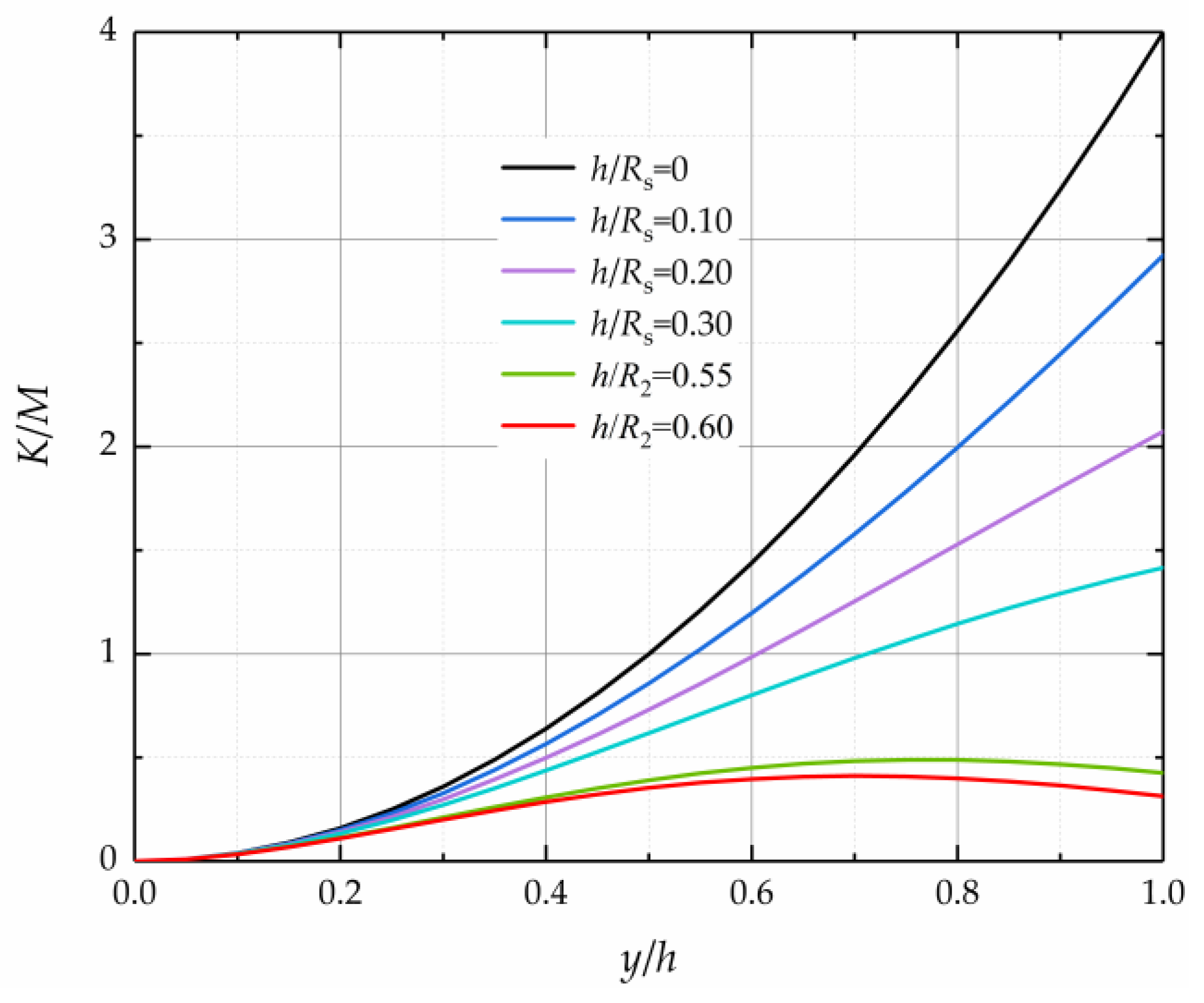
It is found from Equation (13) that K is a function about y / h and h / R s . Generally, the width of the air gap is within 1 mm for permanent magnet synchronous motor used in EHA, and the order magnitude of h / R s is usually less than 10−1. Figure 2 reflects the relationship between K / M and y / h at different values of h / R s , in which M is a constant value at a certain rotation speed, and it can be expressed as M = R e R r 2 ( R r + R s ) . As can be seen from Figure 2, the value of K increases with increasing y / h for a given h / R s less than 0.3 and the maximum value of K is reached when y / h = 1.0 . Therefore, the expression for the maximum value of K can be written as
K m a x = R e R r 2 ( R r + R s ) ( 1 h R s ) 2 ( 2 h R s ) 2
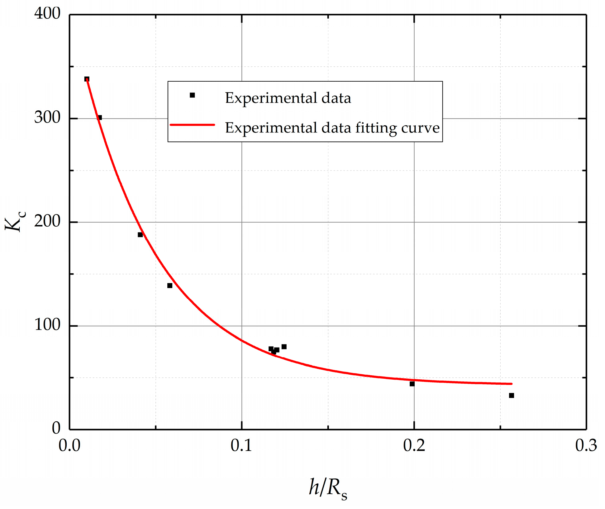
The calculation of the critical coefficient K c is a strong nonlinear and strong coupling process, which is generally difficult to solve. By summarizing the previously published experimental data on Taylor flow stability, the relationship between K c and h / R s is shown in Figure 3, which was prepared based on the results presented in [11,14,16,29,30,31,32]. The functions of the K c and h / R s can be expressed as the following by using nonlinear fitting.
K c = 365.7 e ( h / R s 0.047 ) + 42.5
As the above analysis, for a specific motor structure size, the critical coefficient K c can be obtained using Equation (15), and the critical rotational speed can be calculated by Equations (2) and (14) when K max = K c . Therefore, the viscous loss can be calculated according to different oil states, and the next section will analyze the calculation method of the viscous loss under different oil flow states.

3. Theoretical Analysis of Air Gap Viscous Loss

3.1. Calculation Method of Viscous Loss in Laminar State

The expression of fluid shear stress in laminar flow state can be expressed as
τ L = μ ( u r u r ) = μ 2 B r 2
Hence, for r = R r , the shear stress acting on the rotor can be expressed as
τ L = 2 μ ω r R s 2 R s 2 R r 2
In addition, for the surface area of the rotor in the motor is 2 π R r L , the viscous loss power is
P L = 4 μ π ω r 2 L R r 2 R s 2 R s 2 R r 2
where L is the length of the air gap (m).

3.2. Calculation Method of Viscous Loss in Turbulent State

Since the oil velocity changes irregularly in the turbulent state, the viscosity loss of the motor can no longer be calculated according to Equation (18). This paper will adopt the conservation of momentum theory to analyze the viscosity loss of a motor in a turbulent state.
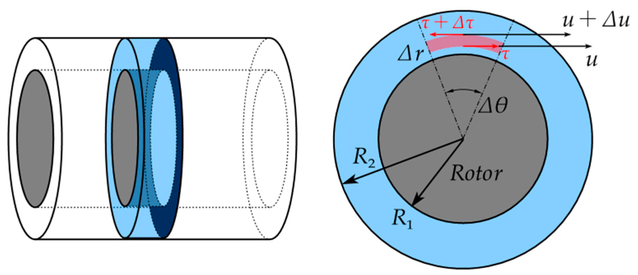
Take an axial section of the air gap and simplify the movement of the oil in the air gap to a plane parallel flow, as shown in Figure 4 The x-axis is selected on the surface of the rotor, and the y-axis is in the radial direction. In addition, the time-averaged velocity distribution in the x-direction can be represented by v = v ( y ) , and the time-averaged velocity in the y-direction is 0.
Assume that the oil in the air gap has two layers, layer 1 and layer 2. In addition, the velocity of the fluid in layer 1 can be expressed as v 1 = v while the layer 2 is v 2 = v + l ( d v / d y ) according to Newton’s law of internal friction. At a certain moment, the oil particles in layer 1 enter layer 2 at speed u . Hence, the mass of oil passing through the microelement area d A in d t time can be expressed as
Δ m = ρ u d A d t
In addition, there is a velocity change v in the x-direction after the oil flowing from layer 1 to layer 2. As a result, the momentum change in the oil can be written as
Δ p = Δ m v = ρ u v d A d t
According to the momentum theorem, the momentum change rate of the oil is equal to the tangential force which can be written as
F T = ρ u v d A
Therefore, the shear stress under turbulent conditions is
τ T = ρ u v
The viscous loss power can be obtained as
P T = τ T A R r ω r = 2 π ρ R r 2 ω L u v
The theoretical models for calculating viscous loss in laminar and turbulent states are obtained in the above. It should be noted that the viscous loss in the turbulent state is related to the fluid velocities u and v . However, velocities u and v cannot obtain accurate analytical solutions. Since the speed u and v can be expressed as the functions of ω , a turbulent coefficient λ is introduced, and the loss power equation can be rewritten as
P T = τ T A R r ω r = 2 π λ ρ R r 2 ω 3 L
In addition, it should be noted that λ is difficult to calculate by the analytical method under a turbulent state. Typically, the value of λ is mainly fitted by experimental data, which will cause greater time. To optimize the lumped parameter model of viscous loss in a turbulent state, this paper established a computational fluid dynamics (CFD) model of the motor air gap. The shear stress on the rotor surface can be obtained using CFD software. Then the viscous loss power can be acquired by integrating the shear stress, which can be expressed as the following:
P T = τ T ds R r ω
Table 1 shows the domain dimensions of the motor and the oil property parameters. As the small slot opening has little influence on the viscous loss [19], the slot opening was neglected in the model. The geometry and mesh of the simulation model are shown in Figure 5, and the number of grid nodes was finally determined to be 10*290*334 in the radial, circumferential, and axial directions. By substituting the parameters of the motor into the Equation (15), K c = 272 was obtained. Introducing K c = K max into Equations (14) and (2), the critical rotation speed was calculated as ω = 357 rad / s (3500 rpm). In contrast, for a motor with the same structure size, the critical speed obtained by Taylor’s criterion was 4570 rpm, employing the lamer model and standard k ε turbulence model, respectively, the viscous loss was obtained. The setup of General, Models, Material, Boundary Conditions are shown in Table 2.
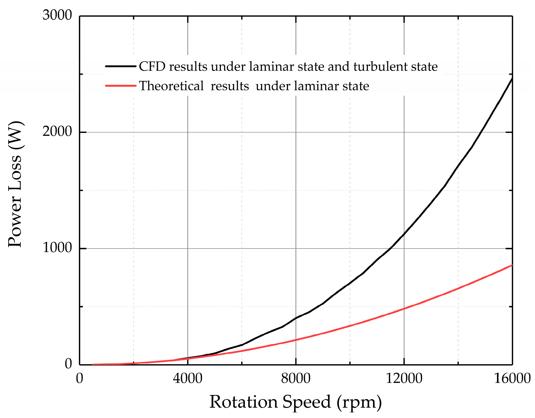
As shown in Figure 6, the results of the viscous loss at various speeds are presented based on the CFD method and traditional calculation method of Equation (18). It can be shown that the results were more consistent in low rotation speed. However, there was a relatively large disagreement at high speed caused by the flow states change. Therefore, the effect of different oil states on the viscosity loss of high-speed motors needs to be considered.
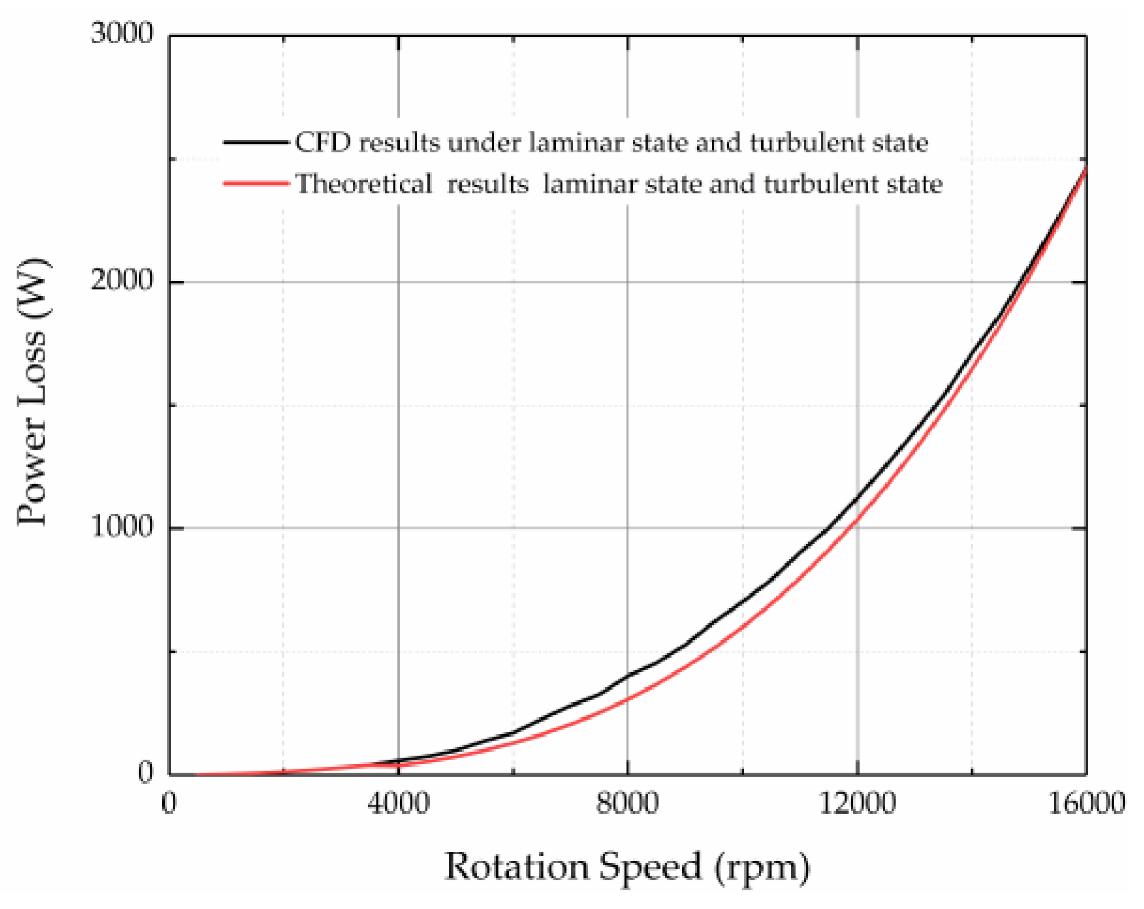
On the other hand, the value of the turbulent coefficient λ was obtained as 1.17135 × 10⁻⁶ based on the CFD simulation results, and the theoretical results and CFD simulation results are shown in Figure 7. Above all, the expression of the viscous loss of the motor under different flow conditions can be rewritten as
P = { 4 μ π ω r 2 L R r 2 R s 2 R s 2 R r 2 ω < 367 rad / s 2.3427 π ρ R r 2 ω 3 L × 10 6 ω > 367 rad / s

4. Experimental Results

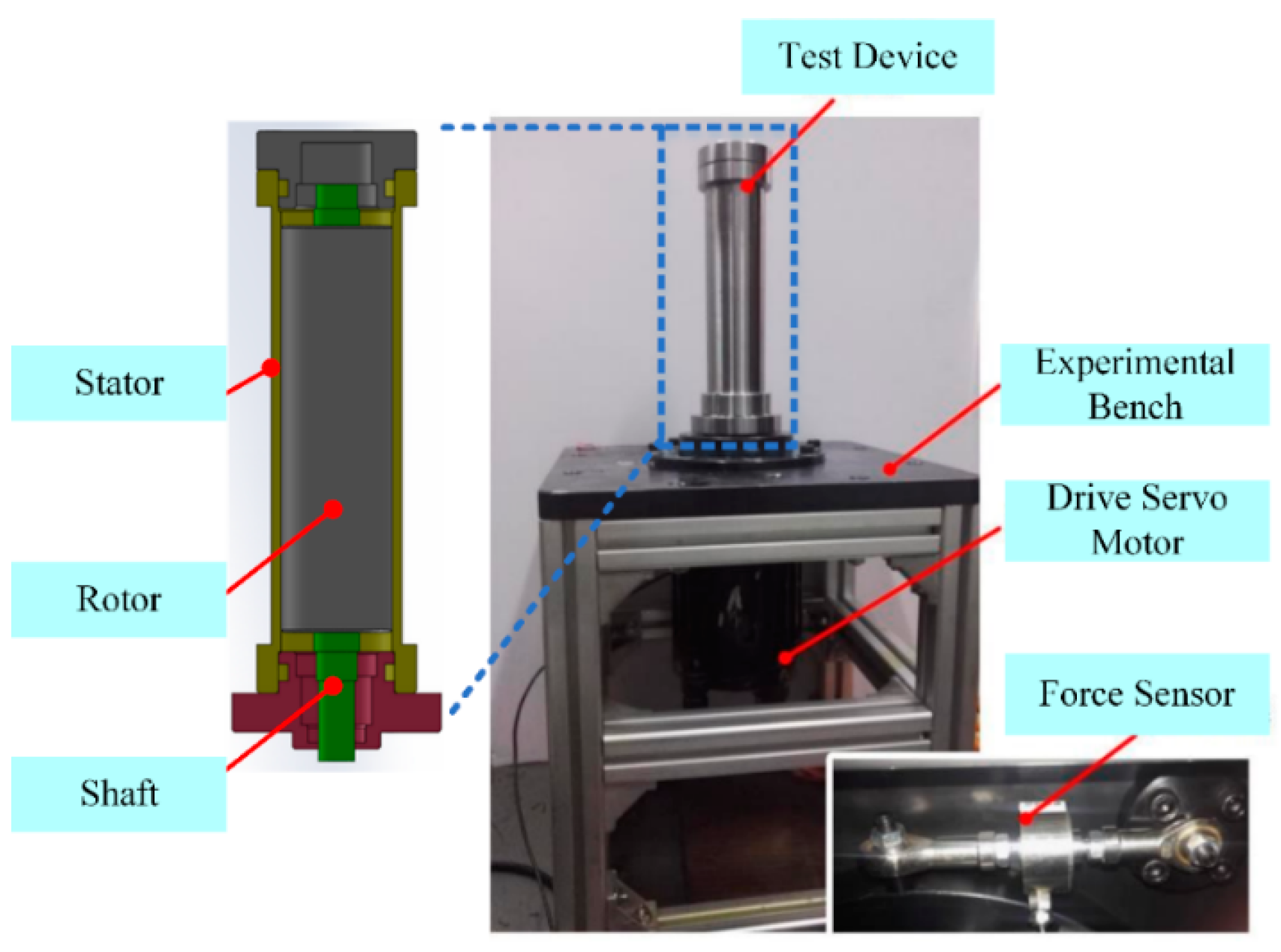
A test rig was designed to verify the proposed criteria for judging the state of the fluid in the air gap and the viscous loss model, as shown in Figure 8. The test rig comprised an experimental bench, a drive servo motor, a force sensor, and a geometrically representative motor model, including a rotor and a stator that could be filled with oil. The novelty of the experimental device was that the force balance method was used to indirectly measure the torque of the motor shaft through the force sensor instead of the torque sensor, which could increase the length of the connecting shaft system.
Therefore, the viscous loss could be obtained by subtracting the motor shaft torque loss without oil from the torque loss filled with oil at the same test stand. The experimental viscous loss power could be expressed as [33]
P = M t e s t ω = ( M w e t M d r y ) ω
where M t e s t is the experimental viscous loss torque, M w e t is the experimental torque loss filled with oil, M d r y is the experimental torque loss without oil.
The comparisons of the viscous loss power between the measured results and the theoretical results at variable rotation speeds were illustrated in Figure 9. It was shown that the experimental results were in the same trend as the theoretical calculation results, which verified the effectiveness of the method of calculating the critical rotation speed in this article. However, there was about a 10% difference due to the viscous loss caused by the end face of the rotor being ignored in the theoretical calculation. In addition, it was feasible to consider the viscous loss in the air gap as the overall viscous loss of the motor due to the difference of the viscous loss was small.

5. Discussion

This paper presents a simulation-based calculation method of EHA motor viscous loss, and a lumped parameter model was proposed under different flow states. Since Taylor’s criterion is not applicable to the judgment of the fluid flow state inside a concentric cylinder with a small air gap, the energy gradient theory was adopted in this paper. In this theory, a parameter K related to the motor structure parameters and rotation speed was proposed, and the flow state of the oil in the air gap changed when the value of K exceeded the critical value Kc obtained by the experimental data. Using this method, the critical speed of the wet EHA motor’s internal gap fluid flow state was 3500 rpm, while the criterion rotation speed was 4570 rpm obtained by using the Taylor criterion. Then the lumped parameter models of the viscous loss under laminar and turbulent state were analyzed by using Newton’s internal friction theorem and the conservation of momentum theory, respectively. To verify the accuracy of the fluid flow state judgment criteria and the proposed lumped parameter model, a motor viscosity loss experiment was designed. There was a 10% error between experimental results and theoretical results, which verified the correctness of the method.

Author Contributions

Investigation, Y.L.; Simulation and Analysis, Y.L. and T.Y.; Methodology, Y.L.; Writing and Editing, Y.L.; Validation, Y.S.; Project Administration, Z.J. All authors have read and agreed to the published version of the manuscript.

Funding

This research was supported by the National Nature Science Foundation of China (No.51890882).

Conflicts of Interest

The authors declare that there is no conflict of interest regarding the publication of this paper.

Appendix A

Taking a microelement in the motor air gap fluid, as shown in Figure A1. The work of viscous shear force acting on the microelement away from the rotor surface can be defined as the following:
W out = ( τ + Δ τ ) [ ( r + Δ r ) Δ θ ] Δ z ( u + Δ u ) d t
where Δ θ is the angular range of the microelement in the cylindrical coordinate system(rad), Δ z is the depth of the microelement in the axial direction(m), τ is the shear stress(N/m2) and it can be written as
τ = μ ( u r u r ) = μ 2 B r 2
where the negative sign indicates the direction of the force is opposite to the movement.
Figure A1. Schematic diagram of the velocity and force of fluid micro-element in the air gap.
Processes 08 00975 g0a1
Similarly, the equation of the work on the surface of the element near the rotor surface can be expressed as
W in = τ ( r Δ θ ) Δ z u d t
The volume of fluid passing through the width of Δ r in dt time is
Δ Q = Δ r Δ z u d t
According to Equations (A1)–(A4), the work of the viscous force acting on the unit volumetric fluid can be written as
Δ H = Δ W Δ Q = W out W in Δ Q = ( τ u Δ u Δ r + τ r + Δ τ Δ r ) r Δ θ
The length of the microelement in streamline direction is
Δ s = r Δ θ
According to Equations (A5) and (A6), the gradient of the total energy in streamline direction can be expressed as
Δ H Δ s = τ u Δ u Δ r + τ r + Δ τ Δ r
Thus, when the value of Δ r tends to infinitesimal and introducing Equations (A6) and (A2) into (A7), the energy loss gradient is
H s = τ u d u d r + τ r + d τ d r = μ 4 B 2 r 4 ( A r + B r ) 1

References

  1. Song, B.; Lee, D.; Park, S.Y.; Baek, Y.S. Design and Performance of Nonlinear Control for an Electro-Hydraulic Actuator Considering a Wearable Robot. Processes 2019, 7, 389. [Google Scholar] [CrossRef] [Green Version]
  2. Xue, L.; Wu, S.; Xu, Y.; Ma, D. A Simulation-Based Multi-Objective Optimization Design Method for Pump-Driven Electro-Hydrostatic Actuators. Processes 2019, 7, 274. [Google Scholar] [CrossRef] [Green Version]
  3. Kargov, A.; Werner, T.; Pylatiuk, C.; Schulz, S. Development of a miniaturized hydraulic actuation system for artificial hands. Sens. Actuators A Phys. 2008, 141, 548–557. [Google Scholar] [CrossRef]
  4. Samer, A.; Fethi, B.O.; Faycal, N.; Gordon, G. High performance Integrated Electro-Hydraulic Actuator for robotics. Part II: Theoretical modelling, simulation, control & comparisons with real measurement. Sens. Actuators A Phys. 2001, 169, 124–132. [Google Scholar]
  5. Jose, V.C.; Adrian, B. Integrative thermodynamic optimization of the environmental control system of an aircraft. Int. J. Heat Mass Transf. 2001, 44, 3907–3917. [Google Scholar]
  6. Ponomarev, P.; Polikarpova, M.; Pyrhönen, J. Thermal modeling of directly-oil-cooled permanent magnet synchronous machine. In Proceedings of the 2012 XXth International Conference on Electrical Machines, Marseille, France, 2–5 September 2012; pp. 1882–1887. [Google Scholar]
  7. Maré, J.C. Aerospace Actuators 2, Single-by-Wire and Power-by-Wire; Great Britain and the United States by ISTE Ltd.: London, UK; John Wiley & Sons, Inc.: Hoboken, NJ, USA, 2017; pp. 134–169. [Google Scholar]
  8. Shang, Y.; Li, X.; Qian, H.; Wu, S.; Pan, Q.; Huang, L. A Novel Electro Hydrostatic Actuator System with Energy Recovery Module for More Electric Aircraft. IEEE Trans. Ind. Electron. 2020, 67, 2991–2999. [Google Scholar] [CrossRef]
  9. Zhang, J.; Li, Y.; Xu, B.; Chen, X.; Pan, M. Churning losses analysis on the thermal-hydraulic model of a high-speed electro-hydrostatic actuator pump. Int. J. Heat Mass Transf. 2018, 127, 1023–1030. [Google Scholar] [CrossRef]
  10. Chandrasekhar, S. Hydrodynamics and Hydromagnetic Stability; Courier Corporation: Dover, UK, 1961; pp. 272–381. [Google Scholar]
  11. Drazin, P.G.; Reid, W.H. Hydrodynamic Stability, 2nd ed.; Cambridge University Press: Cambridge, UK, 2004; pp. 69–123. [Google Scholar]
  12. Chossat, P.; Iooss, G. The Couette–Taylor Problem; Springer: Berlin, Germany, 1994. [Google Scholar]
  13. Schlichting, H. Boundary Layer Theory, 7th ed.; Springer: Berlin/Heidelberg, Germany, 1979; pp. 83–111, 449–554. [Google Scholar]
  14. Andereck, C.D.; Liu, S.S.; Swinney, H.L. Flow regimes in a circular Couette system with independently rotating cylinders. J. Fluid Mech. 1986, 164, 155–183. [Google Scholar] [CrossRef] [Green Version]
  15. Marcus, P.S. Simulation of Taylor-Couette flow. Part 2. Numerical results for wave-vortex flow with one travelling wave. J. Fluid Mech. 1984, 146, 65–113. [Google Scholar] [CrossRef] [Green Version]
  16. Taylor, G.I. Stability of a viscous liquid contained between two rotating cylinders. Philos. Trans. R. Soc. Lond. Ser. A 1923, 223, 289–343. [Google Scholar]
  17. Dou, H.S.; Khoo, B.C.; Yeo, K.S. Instability of Taylor–Couette flow between concentric rotating cylinders. Int. J. Therm. Sci. 2008, 47, 1422–1435. [Google Scholar] [CrossRef] [Green Version]
  18. Sangha, P.S.; Sawata, T.; Yon, J.; Mellor, P.H. Assessment of fluid drag loss in a flooded rotor electro-hydrostatic actuator motor. In Proceedings of the 2015 IEEE International Electric Machines & Drives Conference (IEMDC), Coeur d’Alene, ID, USA, 10–13 May 2015; pp. 139–142. [Google Scholar]
  19. Qi, W.; Zou, J.; Li, J. Numerical calculation of viscous drag loss of oil-filled BLDC motor for underwater applications. In Proceedings of the 2010 International Conference on Electrical Machines and Systems, Incheon, Korea, 10–13 October 2010; pp. 1739–1742. [Google Scholar]
  20. Nerg, J.; Rilla, M.; Pyrhonen, J. Thermal Analysis of Radial-Flux Electrical Machines with a High Power Density. IEEE Trans. Ind. Electron. 2008, 55, 3543–3554. [Google Scholar] [CrossRef]
  21. Wendt, F. Turbulent Stromungen zwischen zwei rotierenden konaxialen Zylindern. Ing. Arch. 1933, 9, 577–595. [Google Scholar] [CrossRef]
  22. Yamada, Y. Torque resistance of a flow between rotating co-axial cylinders having axial flow. Bullentin JSME 1962, 5, 634–642. [Google Scholar] [CrossRef] [Green Version]
  23. Dou, H.S. Mechanism of flow instability and transition to turbulence. Int. J. Non Linear Mech. 2006, 41, 512–517. [Google Scholar] [CrossRef]
  24. Dou, H.S. Physics of Flow Instability and Turbulent Transition in Shear Flows; National University of Singapore: Singapore, 2006. [Google Scholar]
  25. Dou, H.S.; Khoo, B.C.; Yeo, K.S. Turbulent transition in plane Couette flows. In New Trends in Fluid Mechanics Research; Zhuang, F.G., Li, J.C., Eds.; Springer: Berlin/Heidelberg, Germany, 2007. [Google Scholar] [CrossRef] [Green Version]
  26. Dou, H.S. Three important theorems for flow stability. In New Trends in Fluid Mechanics Research; Zhuang, F.G., Li, J.C., Eds.; Springer: Berlin/Heidelberg, Germany, 2007. [Google Scholar] [CrossRef]
  27. Dou, H.S. Energy Gradient Theory of Hydrodynamic Instability. In Proceedings of the Third International Conference on Nonlinear Science, Singapore, 30 June–2 July 2004; Available online: http://arxiv.org/abs/nlin.CD/0501049 (accessed on 11 August 2020).
  28. Dou, H.S.; Khoo, B.C.; Yeo, K.S. Energy loss distribution in the plane Couette flow and the Taylor–Couette flow between concentric rotating cylinders. Int. J. Therm. Sci. 2007, 46, 262–275. [Google Scholar] [CrossRef] [Green Version]
  29. Coles, D. Transition in circular Couette flow. J. Fluid Mech. 1965, 21, 385–425. [Google Scholar] [CrossRef] [Green Version]
  30. Snyder, H.A. Stability of rotating Couette flow. II. Comparisons with numerical results. Phys. Fluids 1968, 11, 1599–1605. [Google Scholar] [CrossRef]
  31. Gollub, J.P.; Swinney, H.L. Onset of turbulence in a rotating fluid. Phys. Rev. Lett. 1975, 35, 927–930. [Google Scholar] [CrossRef]
  32. Hinko, K.A. Transitions in the Small Gap Limit of Taylor-Couette Flow; The Ohio State University Physics Summer Institute, REU Summer: Columbus, OH, USA, 2003. [Google Scholar]
  33. Zhang, J.; Li, Y.; Xu, B.; Pan, M.; Lv, F. Experimental Study on the Influence of the Rotating Cylinder Block and Pistons on Churning Losses in Axial Piston Pumps. Energies 2017, 10, 662. [Google Scholar] [CrossRef] [Green Version]
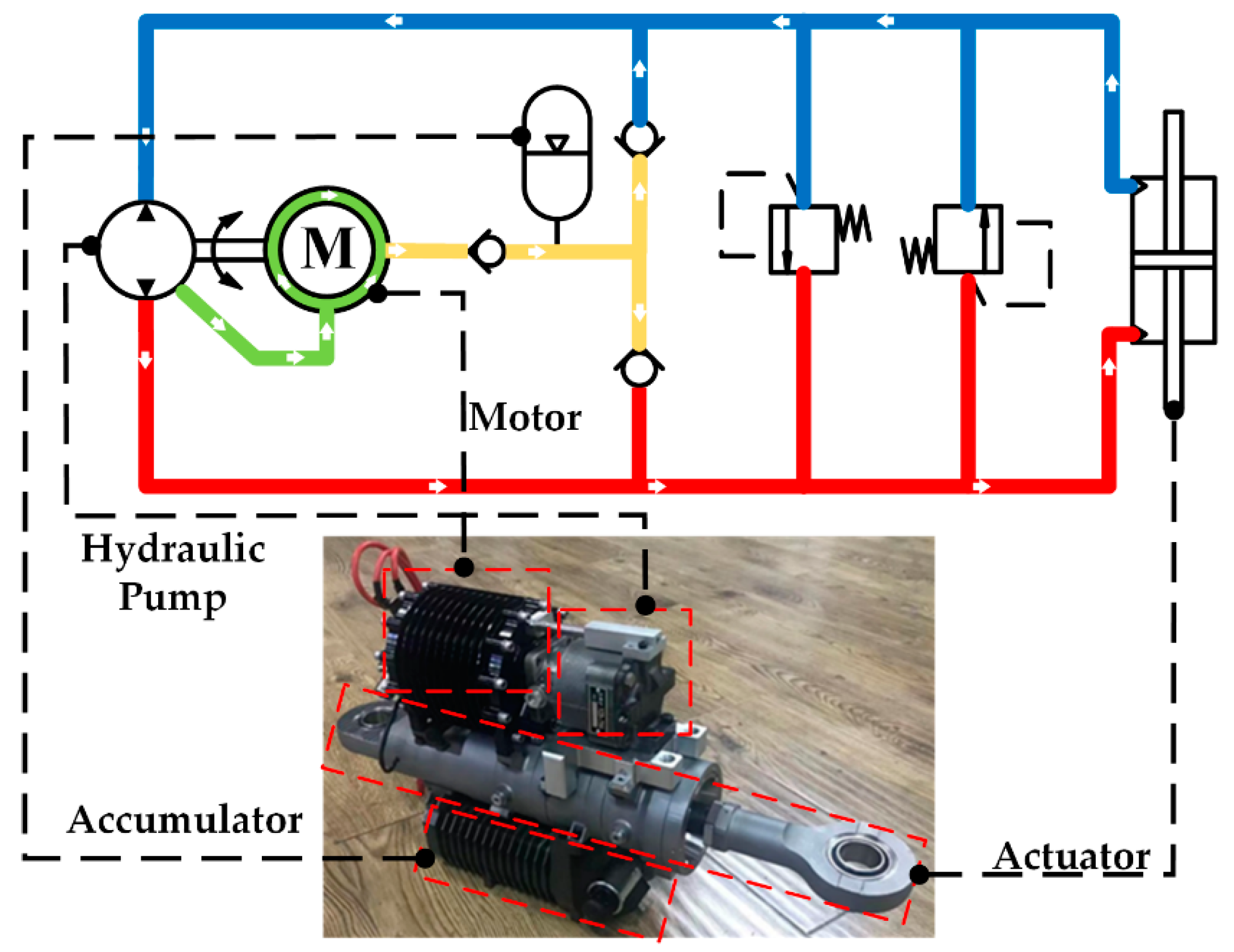
Figure 1. Highly integrated electro-hydrostatic actuator (EHA) system.
Processes 08 00975 g001
Figure 2. K / M value change trend graph about y / h .
Processes 08 00975 g002
Figure 3. The critical coefficient K c value change trend graph about h / R s .
Processes 08 00975 g003
Figure 4. Velocity change diagram of fluid micro-cells under turbulent flow.
Processes 08 00975 g004
Figure 5. CFD simulation model. (a) Geometry of the air gap. (b) Radial grid of air gap. (c) Axial grid of air gap.
Processes 08 00975 g005
Figure 6. Comparison chart of theoretical results based on laminar flow theory and CFD simulation results under laminar state and turbulent state.
Processes 08 00975 g006
Figure 7. Comparison chart of theoretical results and CFD simulation results under laminar state and turbulent state.
Processes 08 00975 g007
Figure 8. Test rig that was used to conduct the experiments of this research.
Processes 08 00975 g008
Figure 9. Comparison of theoretical calculation and experimental test of motor loss. (a) Motor rotor torque loss diagram. (b) Motor power loss diagram.
Processes 08 00975 g009
Table 1. The parameters of the electro-hydrostatic actuator (EHA) motor and oil.
ParametersValueUnit
Radius of the rotor R r 2.35 × 10 2 m
Radius of the stator R s 2.3 × 10 2 m
Length of the air gap L 1.67 × 10 1 m
Density of the oil ρ 839.3 kg/m3
Dynamic viscosity of the oil μ 1.16 × 10 2 N s/m2
Kinematic viscosity of the oil ν 1.38 × 10 5 m2/s
Table 2. CFD simulation parameter setting.
Simulation SettingsSetup
GeneralSolver TypePressure-Based
Velocity FormulationAbsolute
TimeSteady
ModelsViscousLaminar/Standard k-epsilon and Standard Wall Functions
BoundaryEnd Face 1Symmetry
End Face 2Symmetry
RotorMoving Wall (Rotation Speed can be set)
StatorWall (No Slip)
MethodSchemaSIMPLEC