Article

Study on Clearance-Rubbing Dynamic Behavior of 2-DOF Supporting System of Magnetic-Liquid Double Suspension Bearing

1
Fluid Power Transmission and Control Laboratory, Yanshan University, Qinhuangdao 066004, China
2
College of Civil Engineering and Mechanics, Yanshan University, Qinhuangdao 066004, China
3
Jiangsu Provincial Key Laboratory of Advanced Manufacture and Process for Marine Mechanical Equipment, Zhenjiang 212003, China
*
Authors to whom correspondence should be addressed.
Processes 2020, 8(8), 973; https://doi.org/10.3390/pr8080973
Submission received: 13 July 2020 / Revised: 7 August 2020 / Accepted: 8 August 2020 / Published: 12 August 2020
(This article belongs to the Section AI-Enabled Process Engineering)

Abstract

:
As a new type of suspension bearing, Magnetic-Liquid Double Suspension Bearing (MLDSB) is mainly supported by electromagnetic suspension and supplemented by hydrostatic supporting. Its bearing capacity and stiffness can be greatly improved. Because of the small liquid film thickness (it is smaller 10 times than air gap), the eccentricity, crack, bending of the rotor, and the assembly error, it is easy to cause a clearance-rubbing fault between the rotor and stator. The coating can be worn and peeled, the operating stability can be reduced, and then it is one of the key problems of restricting the development and application of MLDSB. Therefore, the clearance-rubbing dynamic equation of 2-DOF system of MLDSB is established and converted into Taylor Series form and the nonlinear components are retained. Dimensionless treatment is carried out by dimensional normalization method. Finally, the rotor displacement response under different rotor eccentricity ratio and rotating speeds is numerically simulated. The studies show that the trajectory of the rotor is periodic elliptic without clearance-rubbing phenomenon when the eccentricity ratio is less than 0.2, while the rotor is greatly affected by the rotation speed and a variety of motions, such as single-period, quasi-period, double-period and chaos, are presented when greater than 0.3. Within the largest range of rotating speed and eccentricity ratio, the rotor presents the single-period trajectory, and then the number of Poincare mapping point is 1, without a clearance-rubbing fault. When the rotational speed is in the scope of (9, 13) krpm and the eccentricity ratio is in the scope of (0.27, 0.4), the number of Poincare mapping point is more than one, the maximum dimensionless rubbing force is −5.7, and then clearance-rubbing fault occurs. The research can provide a theoretical basis for the safe and stable operation of MLDSB.

1. Introduction

The active electromagnetic bearing (AMB) has many defects, such as the insufficient electromagnetic attraction caused by the magnetic pole magnetic saturation, the higher temperature rise in the magnetic pole/coil caused by the copper loss and the eddy current loss [1,2] (the faults of AMB are shown as Figure 1), the bearing characteristics of operation stability of AMB can be limited, and then it becomes “technical bottleneck”, which restricts the further development and application promotion of AMB [3,4].
The hydrostatic bearing concept is introduced into AMB to form the novel suspension bearing-Magnetic-Liquid Double Suspension Bearing (MLDSB) [5]. It is supported by the electromagnetic suspension and supplemented by the hydrostatic supporting, and it has the advantages of an electromagnetic system and hydrostatic system [6]. The bearing capacity and stiffness can be improved drastically [7].
MLDSB is composed of a bracket, motor, coupling, multi-diameter shaft, journal bearing unit, axial bearing unit, journal loading motor, axial loading motor, etc., as in Figure 2 [8].
The journal bearing unit is composed of a rotor, magnetic sleeve, bearing pocket, magnetic pole, inlet hole, shell, coil, etc., as in Figure 3 and Figure 4 [9]. The materials of magnetic pole and magnetic sleeve are cold-rolled non-oriented silicon-steel, and chromium layer is coated in order to solve the problem of matrix corrosion in the lubricants for a long time [10].
The adapting principle of MLDSB is shown as Figure 5. The magnetic suspension system adopts a PD control mode, and the hydrostatic system adopts a constant-pressure supply system [11].
With the development of a bearing-rotor system towards being large-scale and high-power, the design gap between the rotor and stator becomes smaller and smaller, which makes the liquid film thickness of MLDSB reduce by 10 times compared with the traditional electromagnetic air gap [12]. (Air gap = Liquid film + Chromium coating, Liquid film is (30, 50) μm, Air gap is (100, 300) μm).
Moreover, the clearance-rubbing fault between magnetic pole and magnetic sleeve can be caused easily by the eccentricity, crack, bending, improper assembly of rotor; the coating cracks and falls off, and then the operation stability and reliability of MLDSB can be reduced significantly [13].
At present, many scholars have researched the clearance-rubbing fault of a Bearing-Rotor system in detail, and achieved fruitful results. Braut et al. [14] proposed the method and experiment of using Variational Mode Decomposition (VMD) to diagnose partial rotor-stator rubbing. The results showed that the VMD method can effectively analyze the partial rubbing phenomenon in a constant and slightly variable speed operation. Bularevich et al. [15] analyzed regularities of the possible separation of additives and products of tribochemical reactions under sliding friction. The results showed that nonregular oscillations of the force of friction in the tribosystems under study are interpreted as the result of the rupture-healing of adsorbed antifriction layers. Kostyuk et al. [16] studied the rubbing between the absolute rigid rotor and the absolute rigid stator. The results showed that the system model has a simple analytic solution, which deepened the understanding of rubbing phenomenon of readers. Zhang et al. [17] researched nonlinear dynamics of a 5-DOF active magnetic bearings-rotor system and analyzed the rotor motion stability under different conditions. The results showed that there is the phenomenon of stable periodic motion, critical quasi-periodic motion and instable chaotic motion when the system is under different parameter conditions. Zhu et al. [18] analyzed the support damping and radial clearance of the flexible backup bearing on the transient behavior of the rotor. The results showed that the rolling element backup bearing with flexiblity and more damping can greatly improve the dynamic behavior of a rotor drop on rolling element backup bearing.
In sum, the traditional rubbing dynamics research method takes Bearing Body as the rigid supporting unit to analyze dynamic characteristics of a Bearing-Rotor system. MLDSB bears the severe Clearance-Rubbing compound impact load and becomes the weakest link for Bearing-Rotor system [19].
The Clearance-Rubbing fault is the external representation, and dynamic behavior and law is the internal mechanism of MLDSB. Therefore, the 2-DOF clearance-rubbing dynamics equation was established and transformed into Taylor series form with the nonlinear component. Dimensionless processing was adopted through the use of a Dimensional Unitary Method [20]. The displacement response of a rotor is numerical, simulated under different eccentricity ratios and speeds [21].

2. Rubbing Dynamic Model of 2-DOF Supporting System

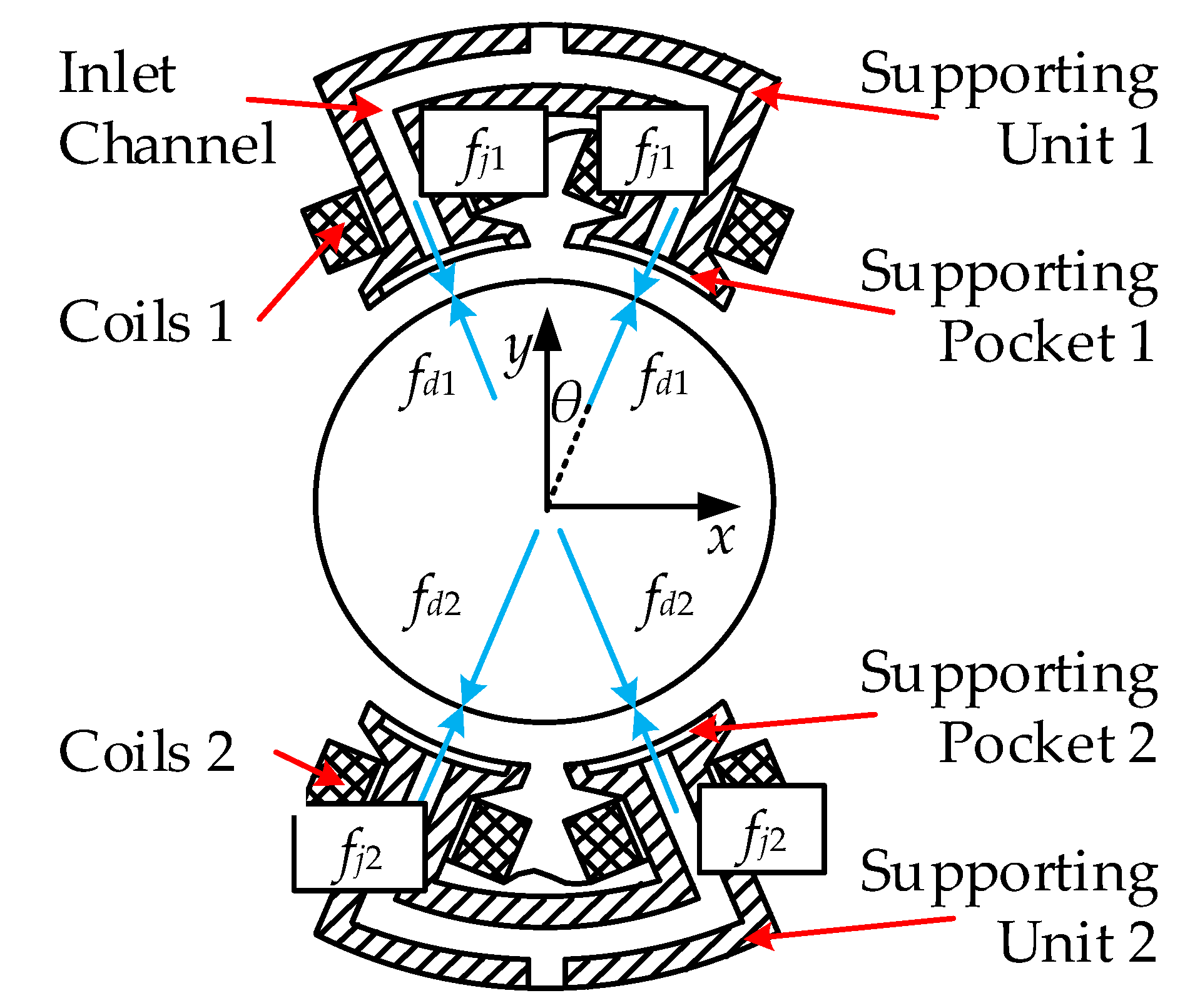
2.1. Rubbing Force Model

Due to the small Clearance-Rubbing time, the assumptions can be shown as follows [22]:
(1)
There is local Elastic Collision and Coulomb Friction between magnetic pole and magnetic sleeve;
(2)
The small gap between two magnetic poles can be ignored;
(3)
The frictional thermal effect between magnetic pole and magnetic sleeve can be ignored;
(4)
The winding leakage, marginal magnetic flux, vortex loss, magnetic material saturation, coupling effect between magnetic poles can be ignored;
(5)
The inertial force and viscous pressure characteristics of the liquid are ignored.
Clearance-Rubbing phenomenon of MLDSB can be shown as Figure 6. o, o1, PT, PN, α, ws, e are, respectively, center of stator, center of rotor, tangential rubbing force, radial rubbing force, angle between rubbing point and x axis, rotation angle, radial displacement [23].
The mathematical expression of rubbing force PN and PT can be shown as follows [24]
{ P N = ( e h 0 ) k c P T = f P N e = x 2 + y 2 h 0
where h0 is liquid film thickness, kc is radial stiffness of stator, f is friction coefficient.
Decompose it in the x and y axis to
{ f x f y } = ( e h 0 ) k c e [ 1 f f 1 ] { x y }
where fx is rubbing force of x axis, fy is rubbing force of y axis.
Equation (2) can be transformed into dimensionless form as follows [25]
{ f X f Y } = ( 1 h 0 e ) h 0 k c [ 1 f f 1 ] { X Y }
where fX is dimensionless rubbing force of x axis, fY is dimensionless rubbing force of y axis, X is dimensionless displacement of x axis, Y is dimensionless displacement of y axis.

2.2. Dynamic Equation of 2-DOF Supporting System

Due to the same supporting structure of x axis and y axis, the force diagram of a y-direction single DOF supporting system can be shown as Figure 7 [26].
The dynamic model of supporting system can be shown as follows [27]
{ m x ¨ + Δ F x + Δ P x = f x + u x m y ¨ + Δ F y + Δ P y = f y + u y
where m is mass of rotor, ΔFx and ΔFy are magnetic force of x and y axis, ΔPx and ΔPy are hydrostatic force of x and y axis, ux and uy are the disturbing force of x and y axis.
(1) ΔFx, ΔFy can be transformed into an increment form as follows [28]
{ Δ F x = μ 0 S N 2 i 0 2 cos θ 2 δ 0 2 [ ( 1 + F x 0 δ 0 2 8 k i 0 2 + P x i 0 x + D x i 0 x ˙ 1 + x δ 0 cos θ ) 2 ( 1 F x 0 δ 0 2 8 k i 0 2 P x i 0 x D x i 0 x ˙ 1 x δ 0 cos θ ) 2 ] Δ F y = μ 0 S N 2 i 0 2 cos θ 2 δ 0 2 [ ( 1 + F y 0 δ 0 2 8 k i 0 2 + P y i 0 y + D y i 0 y ˙ 1 + y δ 0 cos θ ) 2 ( 1 F y 0 δ 0 2 8 k i 0 2 P y i 0 y D y i 0 y ˙ 1 y δ 0 cos θ ) 2 ]
where i0 is bias current, k is electromagnetic coefficient, k = μ0SN2/4, θ is angle between electromagnetic force and y axis, δ0 is air gap, μ0 is air permeability, S is area of magnetic pole, N is number of coil, Fx0, Fy0 are external load of x, y axis, Px, Dx are proportionality and differential coefficient of x axis, Py, Dy are proportionality and differential coefficients of y axis;
(2) ΔPx, ΔPy can be transformed into increment form as follows [29],
{ Δ P x = A ( 1 1 + ( β 1 ) ( 1 x ˜ ) 3 1 1 + ( β 1 ) ( 1 + x ˜ ) 3 ) + 2 A b R h 0 A e cos 2 θ ( 1 ( 1 + x ˜ ) 3 + 1 ( 1 x ˜ ) 3 ) x ˙ Δ P y = A ( 1 1 + ( β 1 ) ( 1 y ˜ ) 3 1 1 + ( β 1 ) ( 1 + y ˜ ) 3 ) + 2 A b R h 0 A e cos 2 θ ( 1 ( 1 + y ˜ ) 3 + 1 ( 1 y ˜ ) 3 ) y ˙
where A is hydrostatic supporting coefficient, A = 2psAecosθ, ps is system pressure, Ae, Ab are supporting area and extrusion area, Rh0 is initial hydraulic resistor, β is throttle ratio, x ˜ = x cos θ / h 0 , y ˜ = y cos θ / h 0 ;
(3) Disturbing force can be shown as follows [30]
{ u x = m e x w s 2 cos ( w s t ) + m e y w s 2 sin ( w s t ) u y = m e x w s 2 sin ( w s t ) + m e y w s 2 cos ( w s t )
where, ex, ey are eccentricity of x and y axis, ws is rotation speed of rotor.
ΔFx, ΔFy, ΔPx, ΔPy can be transformed to Taylor Series with nonlinear part and substituted into Equation (4), and the dimensionless equation can be shown as follows [31,32]
{ X ¨ = 2 ζ x X ˙ β x X φ x 2 X 2 φ x x ˙ X X ˙ + f X + ρ x cos ( w τ ) + ρ y sin ( w τ ) Y ¨ = 2 ζ y Y ˙ β y Y φ y 2 Y 2 φ y y ˙ Y Y ˙ + f Y ρ x sin ( w τ ) + ρ y cos ( w τ )
{ ς x = 1 m w n ( 4 D x i 0 k δ 0 2 + 2 A b A e R h 0 cos 2 θ ) , ζ y = 1 m w n ( 4 D y i 0 k δ 0 2 + 2 A b A e R h 0 cos 2 θ ) β x = 8 k cos θ m w n 2 δ 0 2 ( P x i 0 ( i 0 2 + i x 0 2 ) cos θ δ 0 ) + 12 p s A e ( β 1 ) cos θ m w n 2 β 2 h 0 β y = 8 k cos θ m w n 2 δ 0 2 ( P y i 0 ( i 0 2 + i y 0 2 ) cos θ δ 0 ) + 12 p s A e ( β 1 ) cos θ m w n 2 β 2 h 0 φ x 2 = φ x x ˙ = 0 , φ y 2 = F y 0 h 0 cos θ ( 2 P y + 3 i 0 cos θ L ) i 0 L m w n 2 , φ y y ˙ = 2 D y F y 0 h 0 cos θ i 0 L m w n U x = e x h 0 , U y = e y h 0 , w = w s w n , ρ x = U x w 2 , ρ y = U y w 2
where wn is nature frequency, Ux, Uy are eccentricity ratio of x and y axis.

3. Simulation of Clearance-Rubbing of 2-DOF Supporting System

The initial design parameters of MLDSB can be shown as Table 1.
Uy = 0.1, the influence of design parameters (eccentricity ratio Ux and rotation speed n) on rotor displacement and rubbing force can be shown as follows. In Section 3, all the parameters in the figure are dimensionless except for the rotation speed.

3.1. Influence of Ux on Rotor Displacement

Rotor displacement under different eccentricity ratios, Ux, can be simulated with the fourth-order Runge–Kutta method, as in Figure 8 [33].
According to Figure 8a,b, the rotor keeps stable and its displacement is single trajectory when Ux < 0.2. The displacement has a positive value under the slow rotation speed. As rotation speed increases, the displacement of rotor is translated from a positive value into a negative value, and it reaches the maximum value when n = 9.5 krpm. The rotor displacement reduces to equilibrium state when rotation speed increases again.
According to Figure 8c,d, the rotor changes in the order of single-period, quasi-period, double-period, chaos and single-period when Ux ≥ 0.3 and n ∈ (4.5, 18). As Ux increases, the unstable bifurcation interval and double-period interval increase, as in Table 2.
Ux ∈ (0.2, 0.3) is the transitional interval from a stable single-period motion to an unstable motion, and then it can be analyzed in detail in Section 3.3 in order to determine the critical Ux.

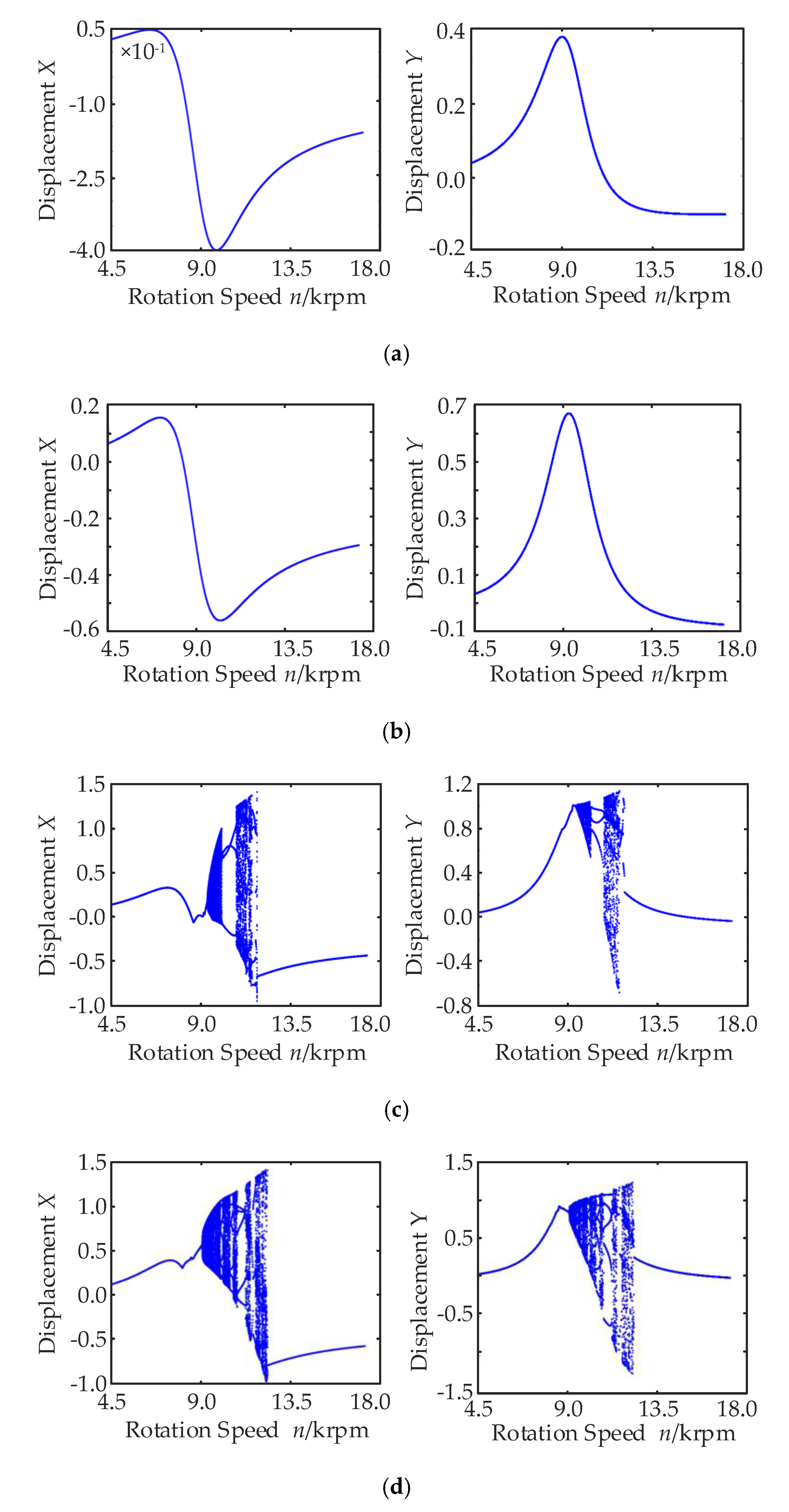
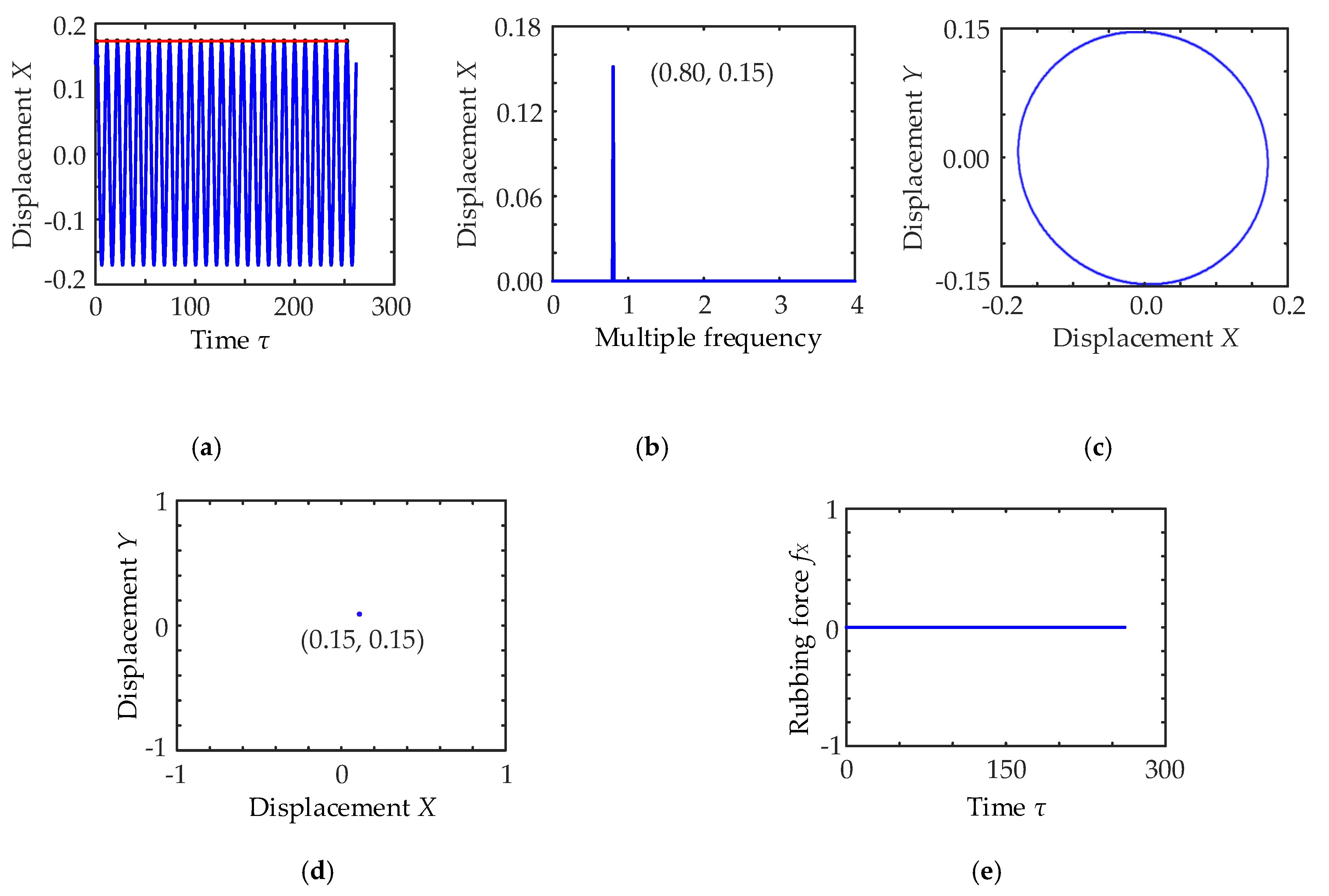
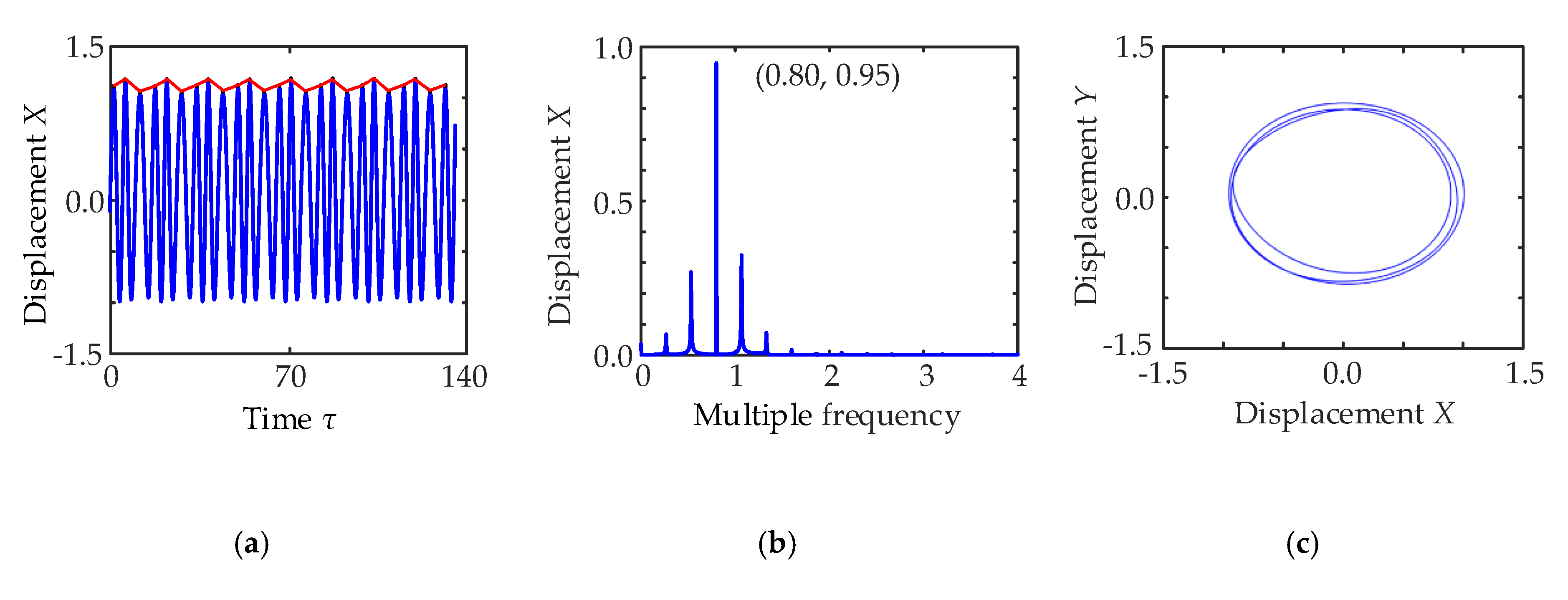
3.2. Influence of Rotation Speed on Rotor Displacement

Take Ux = 0.3, for example, where the bifurcation rule of rotor can be analyzed as in Figure 8c.
The displacement of rotor is the stable single curve when n ∈ (4.5, 9.5). Rotor changes are in the order of quasi-period, double-period, chaos when n ∈ (9.5, 12.5). The displacement of rotor becomes the stable single curve again when n ∈ (12.5, 18), as in Table 3.
According to Table 3, the displacement of the rotor shows the rich dynamic characteristics. Therefore, the rule of the rotor can be analyzed at the different rotational speeds, as shown in the Figures below.
According to Figure 9, when n = 5.5 krpm, the displacement of rotor is the regular sinusoidal motion, as shown in Figure 9a, the single discrete peak occurs in the range of one frequency, as shown in Figure 9b, the mass center of rotor is single closed elliptical trajectory, as shown in Figure 9c, the mapping of Poincare is single point, as shown in Figure 9d, and the dimensionless rubbing force is zero without clearance-rubbing phenomenon, as shown in Figure 9e.
According to Figure 10, when n = 10 krpm, the displacement of rotor is the quasi-period motion (the irregular small-amplitude sinusoidal motion), as shown in Figure 10a, the no common-divisor spectrum occurs in the range of double frequency, as shown in Figure 10b, the mass center of rotor is multi-closed elliptical trajectory, as shown in Figure 10c, the mapping of Poincare is closed loop, as shown in Figure 10d, and the dimensionless rubbing force is 0.8 with clearance-rubbing phenomenon, as shown in Figure 10e.
According to Figure 11, when n = 10.7 krpm, the displacement of rotor is the double-period motion (the irregular sinusoidal motion and the transitional state from quasi-period to chaos state), as shown in Figure 11a, the finite discrete spectrum occurs in the range of double frequency, as shown in Figure 11b, the mass center of rotor is 3-closed elliptical trajectory, as shown in Figure 11c, the mapping of Poincare is 3 points, as shown in Figure 11d, the dimensionless rubbing force is 1.5 with clearance-rubbing phenomenon, and the peak number of rubbing-force decreases, as shown in Figure 11e.
According to Figure 12, when n = 11.5 krpm, the displacement of rotor is the chaos motion, as shown in Figure 12a, the continuous spectrum occurs in the range of double frequency, as shown in Figure 12b, the mass center of rotor is multi irregular overlapped elliptical trajectory, as shown in Figure 12c, the mapping of Poincare is cloud-shaped closed graph, as shown in Figure 12d, the dimensionless rubbing force is 3.0 with clearance-rubbing phenomenon, and the peak number of rubbing-force decreases to the lowest level, as shown in Figure 12e.
According to Figure 13, when n = 13.5 krpm, the displacement of rotor is the single-period sinusoidal motion, as shown in Figure 13a, the single discrete spectrum occurs in the range of one frequency, as shown in Figure 13b, the mass center of rotor is the regular elliptical trajectory, as shown in Figure 13c, the mapping of Poincare is one point, as shown in Figure 13d, and the dimensionless rubbing force is zero without clearance-rubbing phenomenon, as shown in Figure 13e.

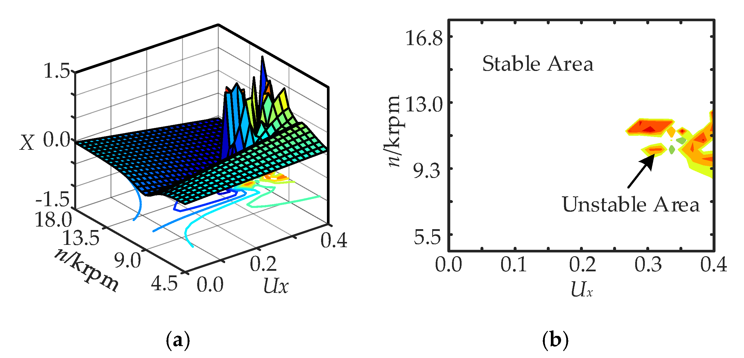
3.3. Influence of Rotor Displacement on Eccentricity Ratio and Rotation Speed

Maximum displacement, number of point and maximum rubbing-force are selected as the indexes of the xt curve, Poincare mapping and clearance-rubbing phenomenon, and then the motion rule of rotor can be analyzed in the range of Ux ∈ (0.2, 0.3), as shown in the Figures below.
According to Figure 14, rotor presentsa single-period trajectory and its amplitude is in the range of (−0.6, 0.3) without clearance-rubbing fault within the largest range, as in the white zone. A series of complicated motions of rotor, such as single-period, double-period and chaos, occurs in turn, and its displacement scope is (−1, 1.5) when n ∈ (9, 13) krpm and Ux ∈ (0.27, 0.4), as in the color zone. The color depth presents the severity of bifurcating phenomenon as color zone of Figure 14b.
According to Figure 15, rotor presents a single-period state without bifurcating phenomenon, and the point number of Poincare mapping is one within the largest range, as in the white zone. A series of points of Poincare mapping occurs and its maximum is up to 15 when n ∈ (9, 13) krpm and Ux ∈ (0.27, 0.4), as in the color zone. The color depth presents the point number of Poincare mapping as the color zone of Figure 15b.
According to Figure 16, there isn’t clearance-rubbing phenomenon and its rubbing force is zero within the most range as white zone. The clearance-rubbing phenomenon occurs and its rubbing-force is −5.7 when n ∈ (9, 13) krpm and Ux ∈ (0.27, 0.4) as color zone. The color depth presents the magnitude of rubbing force as color zone of Figure 16b.
In sum, in order to ensure the stable operation of MLDSB, the rotor should be avoided in the range of n ∈ (9, 13) krpm and Ux ∈ (0.27, 0.4) for a long time.

4. Conclusions

The traditional AMB air gap is 0.1 mm. The bearing will fail when clearance-rubbing fault occurs. Therefore, protective bearings are often added. The hydrostatic bearing concept is introduced into AMB to form the novel suspension bearing MLDSB without protective bearings. In this paper, its operation characteristics and clearance-rubbing fault rules are studied.
When the system rotation speed is close to its natural frequency, it will cause strong resonance, and the eccentricity, crack, bending of the rotor and assembly error will lead to machine faults. Firstly, the clearance-rubbing dimensionless dynamic equation of 2-DOF system of MLDSB is established. Then, rotor displacement under different eccentricity ratios Ux and rotating speeds can be simulated with the fourth-order Runge–Kutta method. Finally, the results show that when the eccentricity ratio is greater than 0.27, the rotor displacement exceeds its liquid film limit during the whole acceleration process and clearance-rubbing fault occurs, so the rotation speed range of resonance is (9, 13) krpm. Simultaneously, the value of rotor eccentricity ratio is not required with a working speed lower than the natural frequency. In the process of rotor acceleration, when the working speed is greater than the natural frequency, its eccentricity should be strictly controlled below 0.27.

Author Contributions

Conceptualization, J.Z.; Data curation, J.Z.; Methodology, J.Z.; Project administration, J.Z.; Resources, J.Z. and Z.W.; Software, W.Y.; Supervision, D.G. and G.D.; Writing—original draft, W.Y.; Writing—review and editing, W.Y. All authors have read and agreed to the published version of the manuscript.

Funding

This work was supported by the National Nature Science Foundation of China (No. 51705445); General project of Natural Science Foundation of Hebei Province (E2020203052); Youth Fund Project of scientific research project of Hebei University (QN202013); Open Project Funding of Jiangsu Provincial Key Laboratory of Advanced Manufacture and Process for Marine Mechanical Equipment and Open Project Funding of Fluid Power Transmission Control Laboratory of Yanshan University.

Conflicts of Interest

The authors declare no conflict of interest.

References

  1. Wu, O.Y.; Qian, J.; Fan, Z.; Yuan, X.Y.; Meng, Q.F. Lubrication model and dynamic characteristics of distributed liquid film for hydrodynamic bearing. Adv. Mat. Res. 2013, 744, 194–198. [Google Scholar] [CrossRef]
  2. Burak, G.; Liang, L.D.; Arash, A.; Huatian, H.; Petre, N.; Naomi, J.H. Monolithic metal dimer-on-film structure: New plasmonic properties introduced by the underlying metal. Nano Lett. 2020, 20, 2087–2093. [Google Scholar]
  3. Mo, N.; Liu, X.N.; Zhou, Y.; Yang, G.J.; Shi, Z.G. Vibration transmission characteristics of active magnetic bearings. J. Vib. Shock 2015, 34, 79–83. [Google Scholar]
  4. Burak, G.; Arash, A.; Mustafa, K.; Raju, S.; Nezih, P. VO2-based reconfigurable antenna platform with addressable microheater matrix. Adv. Electron. Mater. 2017, 3, 1700170. [Google Scholar]
  5. Zhang, W.Y.; Cheng, L.; Zhu, H.Q. Suspension force error source analysis and multidimensional dynamic model for a centripetal force type-magnetic bearing. IEEE Trans. Ind. Electron. 2020, 67, 7617–7628. [Google Scholar] [CrossRef]
  6. Wang, N.; Jiang, D.; Behdinan, K. Vibration response analysis of rubbing faults on a dual-rotor bearing system. Arch. Appl. Mech. 2017, 87, 1891–1907. [Google Scholar] [CrossRef]
  7. Zhang, W.Y.; Yang, H.K.; Cheng, L.; Zhu, H.Q. Modeling based on exact segmentation of magnetic field for a centripetal force type-magnetic bearing. IEEE Trans. Ind. Electron. 2020, 67, 7691–7701. [Google Scholar] [CrossRef]
  8. Ishida, Y.; Inagaki, M.; Ejima, R.; Hayashi, A. Nonlinear resonances and self-excited oscillations of a rotor caused by radial clearance and collision. Nonlinear Dyn. 2009, 57, 593–605. [Google Scholar] [CrossRef]
  9. Xiong, W.L.; Hu, C.; Lv, L.; Zheng, L.G. Research on the influence of controllable restrictor parameters on the characteristics of hydrostatic journal bearing. Chin. J. Mech. Eng. 2018, 54, 63–71. [Google Scholar] [CrossRef]
  10. Hoshi, H.; Tadahiko, S.; Setsuo, T. Third generation blood pumps with mechanical non-contact magnetic bearing. Artif. Organs 2006, 30, 324–338. [Google Scholar] [CrossRef]
  11. Zhang, W.; Zu, J.W.; Wang, F.X. Global bifurcations and chaos for a rotor-active magnetic bearing system with time-varying stiffness. Chaos Soliton Fract. 2008, 35, 586–608. [Google Scholar] [CrossRef]
  12. Wang, H.; Liu, J. Stability and bifurcation analysis in a magnetic bearing system with time delays. Chaos Soliton Fract. 2005, 26, 813–825. [Google Scholar] [CrossRef]
  13. Zhao, Y.; Liu, Q.; Ma, L.; Wang, K. Novel lorentz force-type magnetic bearing with flux congregating rings for magnetically suspended gyrowheel. IEEE Trans. Magn. 2019, 55, 1–8. [Google Scholar] [CrossRef]
  14. Braut, S.; Zigulic, R.; Skoblar, A.; Stimac-Roncevic, G. Partial rub detection based on instantaneous angular speed measurement and variational mode decomposition. J. Vib. Eng. Technol. 2020, 8, 351–364. [Google Scholar] [CrossRef]
  15. Bulgarevich, S.B.; Boiko, M.V.; Lebedinskii, K.S. Adsorption separation of components of liquid lubricant on rubbing surfaces under sliding friction. J. Frict. Wear. 2015, 36, 534–541. [Google Scholar] [CrossRef]
  16. Kostyuk, A.G.; Shatokhin, V.F.; Volokhovskaya, O.A. Specific features relating to the motion of a rotor with rubbing against the stator. Therm. Eng. 2013, 60, 628–634. [Google Scholar] [CrossRef]
  17. Zhang, G.; Yin, Q.Z.; Jiang, D.D.; Liang, S.P. Research on nonlinear dynamics of five-DOF active magnetic bearings-rotor system. Chin. J. Mech. Eng. 2010, 46, 15–21. [Google Scholar] [CrossRef]
  18. Zhu, C.S. Nonlinear dynamics of rotor drop on rolling element backup bearings after active magnetic bearings failure. Chin. J. Mech. Eng. 2006, 42, 200–206. [Google Scholar] [CrossRef]
  19. Cansiz, A.; Yildizer, İ.; McGuiness, D.T. Rotor optimization in a superconducting magnetic bearing by using frozen image model and Amperian current approximation. Cryogenics 2019, 98, 60–66. [Google Scholar] [CrossRef]
  20. Guo, C.; Li, C.G.; Wang, D.Y. Nonlinear dynamic analysis and experiment verification of rubbing faults of rotor-ball bearing-support-stator coupling system for aero-engine. J. Aerosp. Power. 2008, 23, 1304–1311. [Google Scholar]
  21. Dai, X.; Zhang, X.; Jin, X. The partial and full rubbing of a flywheel rotor–bearing–stop system. Int. J. Mech. Sci. 2001, 43, 505–519. [Google Scholar] [CrossRef]
  22. Peng, G.; Li, C.; Cao, C.; Hong, J. Dynamic response and safety design of rotor system with impact excitation. J. Propul. Technol. 2018, 39, 1111–1121. [Google Scholar]
  23. Kankar, P.K.; Sharma, S.C.; Harsha, S.P. Fault diagnosis of ball bearings using machine learning methods. Expert Syst. Appl. 2011, 38, 1876–1886. [Google Scholar] [CrossRef]
  24. Zhang, G.Y.; Huang, H.Z.; Zhou, M.; Chen, Y.; Wei, J.C. A nonlinear dynamic model and its stability for the generator rotor with coupling the unbalanced electromagnetic force and the oil film force. Proc. Chin. Soc. Electr. Eng. 2014, 34, 2406–2413. [Google Scholar]
  25. Yu, H.; Chen, Y.S.; Cao, Q.J. Nonlinear dynamic behavior analysis for a cracked multi-DOF rotor system. J. Vib. Shock 2014, 33, 92–98. [Google Scholar]
  26. Shatokhin, V.F. Patterns of the rotor-over-stator rolling under change in the damping components. Therm. Eng. 2018, 65, 143–150. [Google Scholar] [CrossRef]
  27. Jin, X.; Zhao, M.; Chow, T.W.; Pecht, M. Motor bearing fault diagnosis using trace ratio linear discriminant analysis. IEEE Trans. Ind. Electron. 2013, 61, 2441–2451. [Google Scholar] [CrossRef]
  28. Hua, C.; Ta, N.; Rao, Z. Dynamic characteristics analysis of a rub-impact rubber bearing-shaft system. J. Vib. Control 2015, 21, 388–401. [Google Scholar] [CrossRef]
  29. Ji, X.; Chen, Y. Tribological behavior of babbitt alloy rubbing against Si3N4 and steel under dry friction condition. J. Mater. Eng. Perform. 2016, 25, 750–755. [Google Scholar] [CrossRef]
  30. Xie, Z.Y.; Mou, W.X.; Zhou, H.K.; Wang, X. Variable parameter control of active magnetic bearing rotor system based on rotation speed. J. Vib. Eng. 2012, 25, 739–744. [Google Scholar]
  31. Liu, Y.; Li, Y.; Shi, T.; Ma, H.; Wen, B.C. Study on misalignment-rubbing coupling fault of rotor system supported by oil film force. J. Mech. Eng. 2016, 52, 79–86. [Google Scholar] [CrossRef]
  32. Shang, Y.J.; Lin, J.Z.; Liu, X.j.; Xin, X.W. Impact of hydrostatic bearings on the dynamic performance of electric spindle rotor device. Mech. Sci. Technol. Aeronaut. Eng. 2015, 34, 688–693. [Google Scholar]
  33. Gunerkar, R.S.; Jalan, A.K.; Belgamwar, S.U. Fault diagnosis of rolling element bearing based on artificial neural network. J. Mech. Sci. Technol. 2019, 33, 505–511. [Google Scholar] [CrossRef]
Figure 1. Faults of active electromagnetic bearing (AMB).
Processes 08 00973 g001
Figure 2. Experimental Table of Magnetic-Liquid Double Suspension Bearing (MLDSB).
Processes 08 00973 g002
Figure 3. Radial Journal Unit of MLDSB.
Processes 08 00973 g003
Figure 4. Photo of Radial Journal Unit of MLDSB.
Processes 08 00973 g004
Figure 5. Single Supporting System of MLDSB.
Processes 08 00973 g005
Figure 6. Clearance-Rubbing Model of MLDSB.
Processes 08 00973 g006
Figure 7. Force diagram of y-direction supporting system.
Processes 08 00973 g007
Figure 8. Rotor displacement with different eccentricity ratio. (a) Ux = 0.1, Uy = 0.1; (b) Ux = 0.2, Uy = 0.1; (c) Ux = 0.3, Uy = 0.1; (d) Ux = 0.4, Uy = 0.1.
Processes 08 00973 g008
Figure 9. Rotor displacement when n = 5.5 krpm. (a) x-t; (b) Amplitude spectrum; (c) Rotor trajectory; (d) Poincare mapping; (e) Rubbing force.
Processes 08 00973 g009
Figure 10. Rotor displacement when n = 10 krpm. (a) x-t; (b) Amplitude spectrum; (c) Rotor trajectory; (d) Poincare mapping; (e) Rubbing force.
Processes 08 00973 g010
Figure 11. Rotor displacement when n = 10.7 krpm. (a) x-t; (b) Amplitude spectrum; (c) Rotor trajectory; (d) Poincare mapping; (e) Rubbing force.
Processes 08 00973 g011aProcesses 08 00973 g011b
Figure 12. Rotor displacement when n = 11.5 krpm. (a) x-t; (b) Amplitude spectrum; (c) Rotor trajectory; (d) Poincare mapping; (e) Rubbing force.
Processes 08 00973 g012
Figure 13. Rotor displacement when n = 13.5 krpm. (a) x-t; (b) Amplitude spectrum; (c) Rotor trajectory; (d) Poincare mapping; (e) Rubbing force.
Processes 08 00973 g013
Figure 14. Rotor displacement with different eccentricity ratio and rotation speed. (a) Ux-n-X diagram; (b) Ux-n diagram.
Processes 08 00973 g014
Figure 15. Poincare mapping with different eccentricity ratio and rotation speed. (a) Ux-n-point diagram; (b) Ux-n diagram.
Processes 08 00973 g015
Figure 16. Rubbing force with different eccentricity ratio and rotation speed. (a) Ux-n-fX diagram; (b) Ux-n diagram.
Processes 08 00973 g016
Table 1. Design parameters of MLDSB.
ParametersValueParametersValue
Bias current i01 AFilm thickness h050 μm
System pressure ps 0.1 MpaAngle θ22.5°
Throttle ratio β2 DimensionlessFlow coefficient B ¯ 0.7 Dimensionless
Lubricants viscosity μ1.3 × 10⁻³ pa·sArea of magnetic pole S1080 mm2
Mass of rotor m4 kgNumber of coil N50 Dimensionless
Air permeability μ04π × 10−7 H/mHydraulic resistor Rh01.5 × 10−10 N·s/m
Supporting area Ae416 mm2Friction coefficient f0.2 Dimensionless
Extrusion area Ab56 mm2Stiffness of rotor kc6 × 107 N/m
Bearing bore diameter61 mmBearing length71 mm
Table 2. Unstable Rotation Speed with Different Eccentricity Ratio.
Eccentricity Ratio UxStable Scope 1 Unstable Scope 2 Stable Scope 3
0.30(4.5, 9.5) krpm(4.5, 9) krpm(12.5, 18) krpm
0.40(4.5, 9) krpm(9, 13) krpm(13, 18) krpm
Table 3. Rotor Motion with different Rotation Speed.
Rotation Speed nMotion RuleRotation Speed Test n
(4.5, 9.5) krpmSingle Period5.5 krpm
(9.5, 10.5) krpmQuasi Period10 krpm
(10.5, 11) krpmDouble Period10.7 krpm
(11, 12.5) krpmChaos11.5 krpm
(12.5, 18) krpmSingle Period13.5 krpm

