1. Introduction
The mixing of liquid media is one of the most common operations in the chemical, biochemical, food and consumer industries. The purpose of mixing is to intensify heat and mass transfer and to prepare mixtures of desired properties, e.g., suspensions and emulsions. Three basic forms of mixing are used in mixing equipment—hydraulic, pneumatic and mechanical. For the common flow of substances through a pipeline, shaped inserts in the pipeline are used, ensuring the radial mixing of liquids—so-called static mixers. Mixing equipment with a mechanical rotary agitator, which creates a forced flow in the vessel, is the most often used in industry.
For the purpose of mixing, the most common requirements are the homogenization of the mixed batch and ensuring the suspension of particles in the liquid, which corresponds to data from manufacturers, e.g., published in [
1]. In this publication it is shown that as many as 80% of application processes comprise homogenization, and 50% of processes deal with solid–liquid suspensions. These operations are influenced by the flow of the agitated batch, where the primary flow of the liquid, which mainly affects the suspension of the solid phase, is caused by the pumping effects of the mechanical agitator [
2]. Due to the transfer of momentum between the liquid flowing out of the rotor region of the agitator and the surrounding area, an induced flow is created in the remaining volume, which affects the homogeneity of the agitated batch. The flow and circulation of the agitated batch is influenced by the geometric parameters of the mixing system and, in particular, by the shape of the agitator blades.
For the design, construction and operation of the mixing equipment, it is necessary to determine the required rotation frequency of the agitator so as to ensure the required process takes place in the agitated batch and the correct power input of the agitator shaft is used for dimensioning the driving system. These design parameters, depending not only on the geometric configuration of the mixing equipment (shape of vessel, inserts inside the vessel, the types of agitators and their mutual geometric arrangements) but also on the physical–chemical properties of the agitated batch, are determined experimentally on a geometrically similar model of mixing equipment. The evaluation of experiments in the form of suitable dimensionless process characteristics will then allow for the use of these results in the design of the operating equipment and the choice of the optimal geometric configurations of the equipment, not only in terms of ensuring the required process takes place, but also in terms of the minimization of operating energy costs.
2. Flow in Agitated Batch
2.1. The Characterization of Flow in Agitated Batch
The primary effect of a mechanical agitator is the flow and circulation of the agitated liquid in the vessel. Mechanical rotary agitators, depending on their geometry, cause the axial, radial or tangential flow of the agitated batch in the vessel.
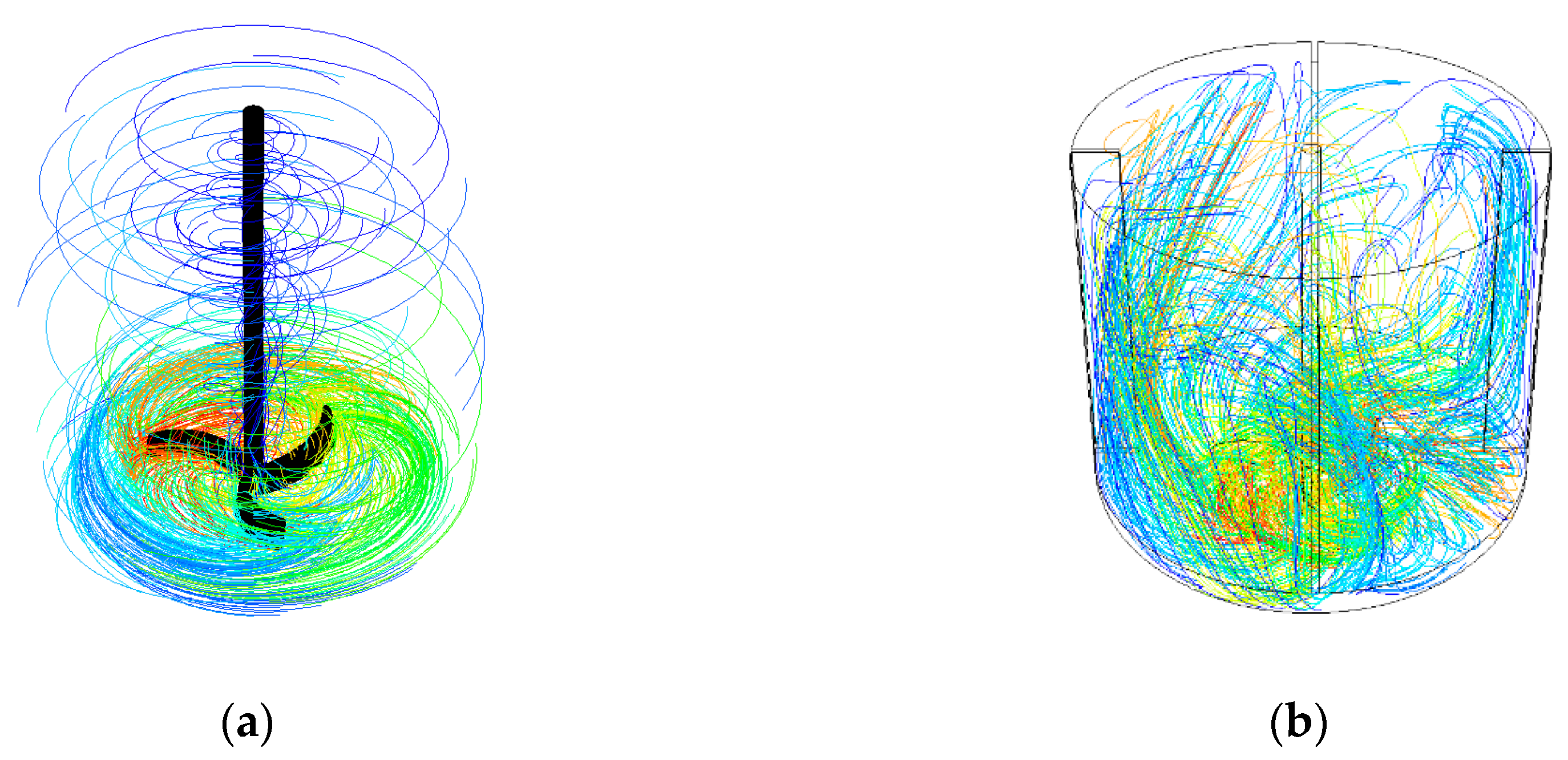
Mixing equipment with a cylindrical vessel and with an axially-arranged mechanical rotary agitator, which creates a forced flow in the vessel, is the most common in the industry. If it is necessary to suppress the tangential flow in the agitated batch and prevent the formation of a central vortex, the cylindrical vessels are equipped with inserts in the form of variously shaped baffles (radial, tubular, finger). These enhance the axial flow and the intensity of circulation in the agitated batch, which results in an extension of the flow to the whole batch and, therefore, has a positive effect on the process of the homogenization of miscible liquids and heterogeneous mixtures in the agitated batch. The effect of the baffle installation on the flow patterns of both an agitated batch in a cylindrical vessel without baffles, and a vessel with four radial baffles and a radial agitator with curved blades, is shown in
Figure 1. The flow pattern is illustrated by the path lines in a turbulent regime, solved by CFD simulation in fluent. In many applications, this is not possible, due, for example, to the sanitation or surface treatment needed to equip the mixing vessel with baffles. In the case of a viscous flow of highly viscous substances, it is possible to enhance the axial flow by suitably configuring the agitator. In the case of a turbulent flow in the mixing vessel without baffles, it is possible to partially suppress the tangential flow by means of an eccentric or obliquely-inclined positioning of the agitator in the mixing vessel.
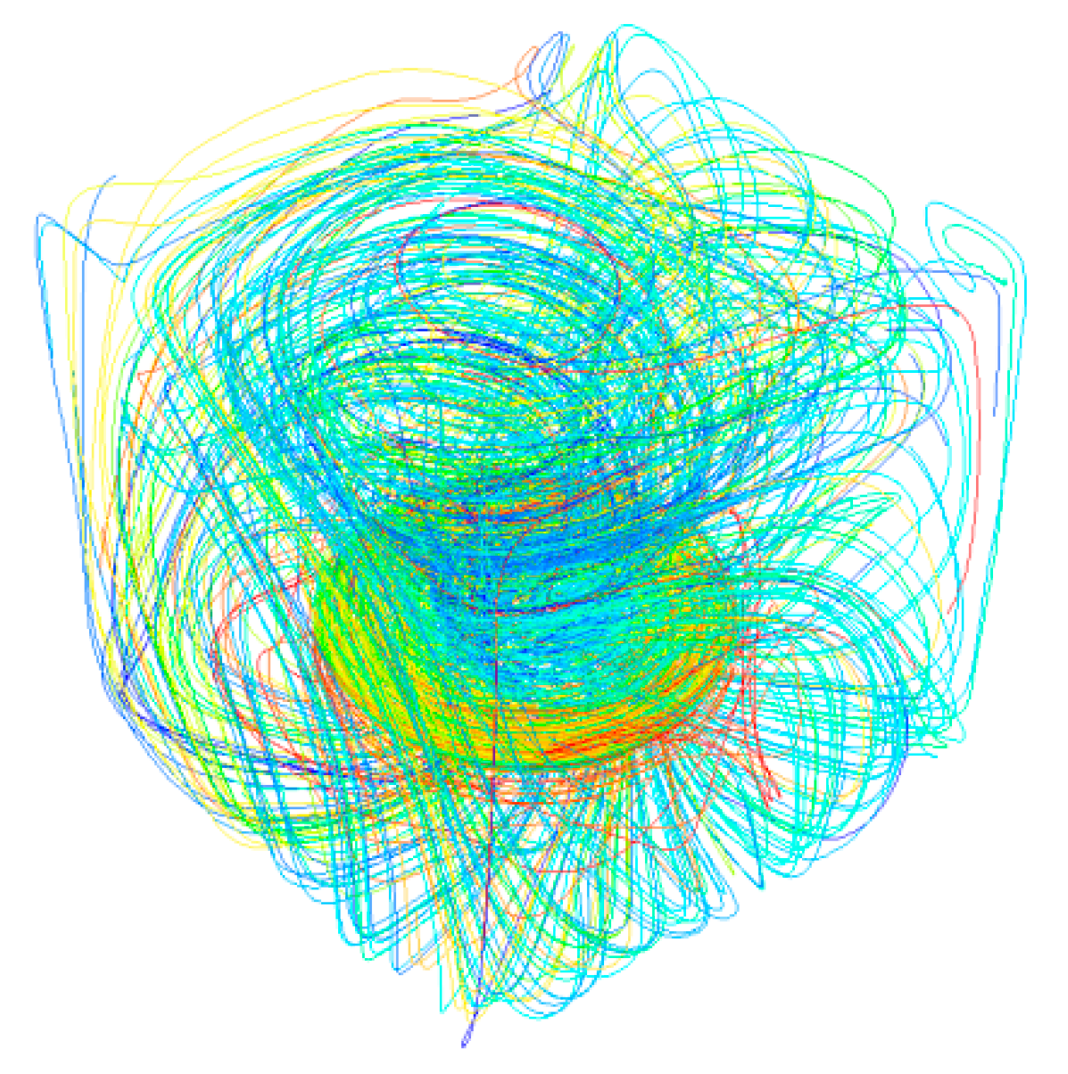
Occasionally, because of the installation plan and space saving, it is necessary to enact the mixing process in a vessel of square or rectangular cross-section. It is evident from
Figure 2 that the sharp corners of the vessel disturb the tangential flow and practically perform the function of radial baffles. For example, the flow field in a rectangular vessel equipped with a side-entering agitator in the laminar region is described in [
3].
2.2. Flow Field in the Agitated Batch
Data about the distribution of velocity and pressure in the agitated fluid can be obtained by solving a system of partial differential equations, i.e., the continuity equation and the Navier–Stokes equation. An analytical solution of this system of equations is not possible due to the complexity of the monitored system of the vessel equipped with the agitator. Therefore, it is necessary to limit oneself only to the inspection analysis of these equations, e.g., [
4], which shows that the dimensionless velocity
and pressure
in geometrically similar systems are a function of dimensionless position
, dimensionless time
and modified Reynolds number
:
The time dependence has a periodic character at a steady flow, which is caused by the geometric shape of the agitator and the vessel. The time dependence of speed and pressure is usually neglected, and the instantaneous quantities are replaced by time-averaged values
:
For large values of the modified Reynolds number, i.e., for the developed turbulent flow, the effect of viscous forces can be neglected. Based on the inspection analysis, Equations (3) and (4) take the form:
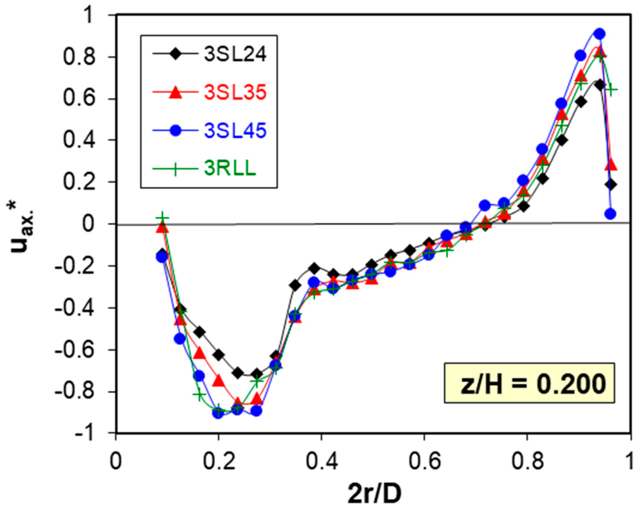
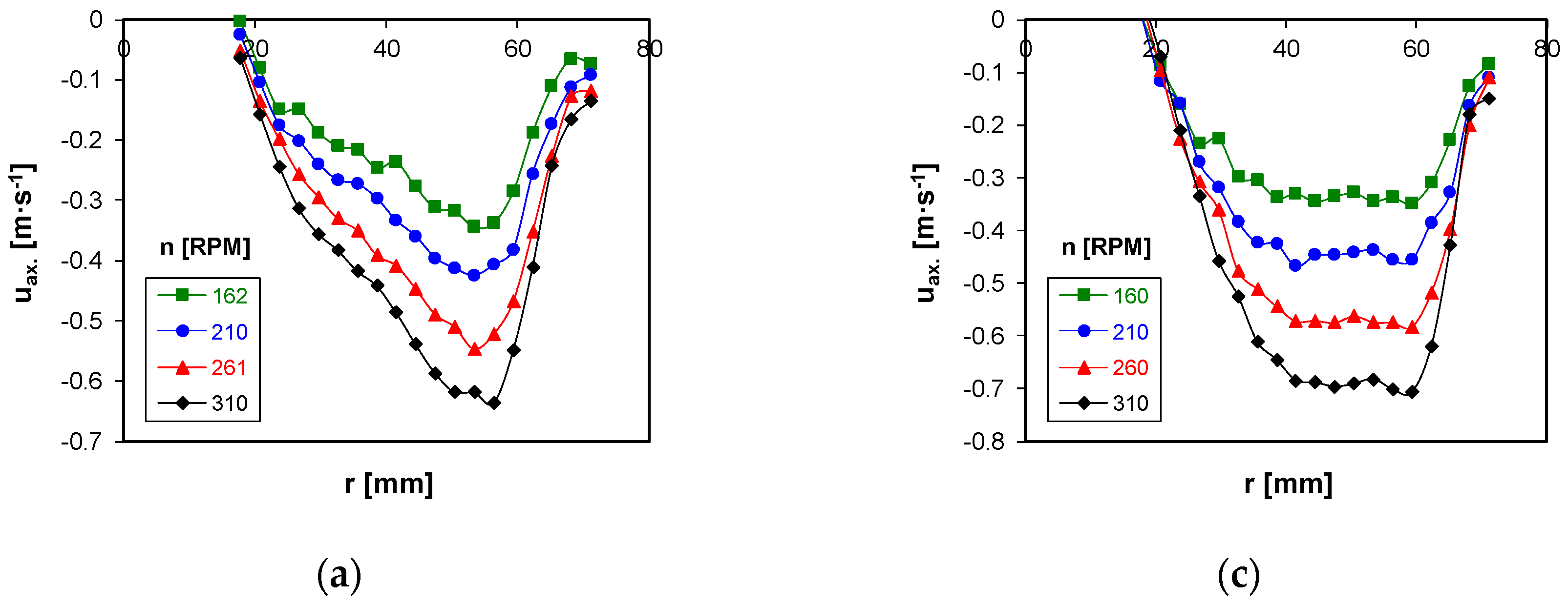
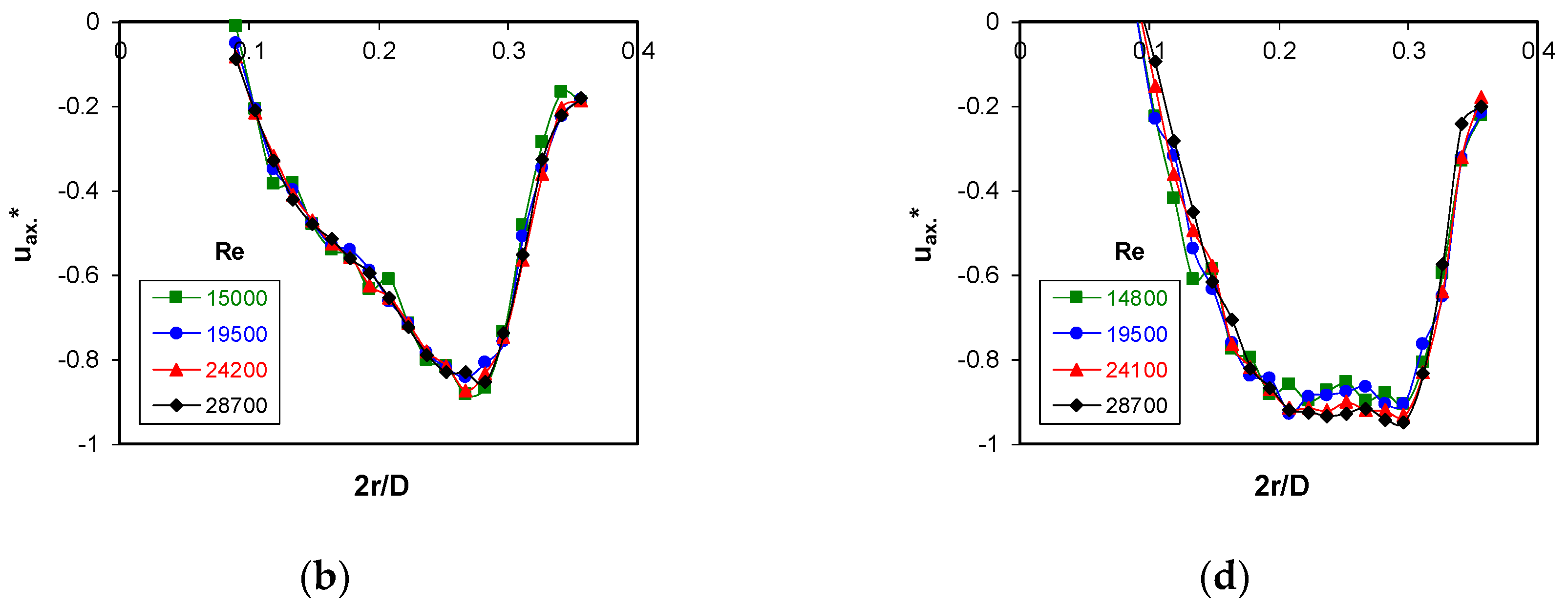
Examples of axial velocity profiles in the agitated batch and in the discharge stream in the rotor region of the agitator are shown in
Figure 3 and
Figure 4 for the turbulent flow caused by the axial flow impeller.
In the region of small values of the Reynolds number (area of the creeping flow), the inertia forces are negligible. Therefore, when converting the Navier–Stokes equation to a dimensionless form, it is necessary to divide this equation by the expression of the term that expresses the effect of viscous forces. Then the definition of dimensionless pressure changes into the form
. From the inspection analysis of the equations adjusted in this way, it follows that:
2.3. Pumping Efficiency of Rotary Agitators
The pumping capacity of an agitator is defined as the volume of liquid leaving the agitator per unit of time. If the velocity field at the discharge of the agitator is known, the pumping capacity can be determined from the equation:
where
S is the surface of a cylinder with a diameter equal to the diameter of the agitator, and a height equal to the axial height of the blades.
After adjusting Equation (9) to a dimensionless form, it follows from the inspection analysis of this equation, e.g., [
4], that for geometrically similar system configurations the dimensionless pumping capacity, the so-called flow number
NQP, is a function of the modified Reynolds number
Re:
For large values of the modified Reynolds number, i.e., for the developed turbulent flow, when considering the dimensionless velocity according to Equation (5), it follows from the inspection analysis that:
This conclusion is valid analogously to the creeping flow when considering the dimensionless velocity according to Equation (7).
The pumping efficiency of agitators is determined either by measuring the mean circulation time of two successive passages of the indicator particle through the control surface, i.e., in this case by an agitator (so-called flow-follower)—e.g., [
7]—or by integrating the measured velocity profiles of the discharge from the agitator according to Equation (9)—e.g., [
8].
The primary flow of a liquid in the agitated batch is caused by the pumping efficiency of the mechanical agitator. Due to the transfer of momentum between the liquid flowing out of the rotor region of the agitator and the surrounding environment, an induced flow is created in the remaining volume. The total volume flow of the agitated batch
QT can then be obtained as the sum of the flow rate power
QP and the induced flow
Qi:
Dividing Equation (12) by
nd3 in dimensionless form yields:
For comparison of hydraulic pumping or the total circulating efficiency of the agitators, a dimensionless energy criterion was proposed [
9] in the form:
or
where
Po is the power number expressing the dimensionless power of the agitator shaft. These criteria express the energy necessary to pump liquid or to develop the required total volumetric flow rate for similar agitated systems. From the inspection analysis of equations expressing the force effects of the liquid acting on the agitator, e.g., [
4], it follows that for geometrically similar arrangements of the mixing equipment, the power number
Po is a function of the modified Reynolds number
Re:
For large values of the modified Reynolds number, i.e., in the turbulent flow region, the power number
Po does not depend on the modified Reynolds number
Re, i.e.,
2.4. Hydrofoil Impellers
It is evident from
Figure 3 and
Figure 4 that the geometric configuration of the agitator and the shape of the agitator blades have a fundamental effect on the velocity distribution in the agitated batch, and they thereby influence the ongoing agitation processes. Currently, there is a trend of designing hydrodynamically optimized agitators with shaped blades called hydrofoil impellers. Most companies producing mixing equipment (e.g., Chemineer, Lightnin, Ekato, and the Czech company Techmix) use their own developed types of hydrofoil impellers. The aim is to design an agitator with shaped blades that direct the flow of the agitated batch as much as possible, while achieving the highest possible hydraulic efficiency, i.e., the highest use of energy supplied to the agitator in the form of its power to induce its pumping power and turbulence dissipated outside the rotor area of the agitator. A comparison of the flow in a vessel with an axial hydrofoil impeller and a standard axial inclined blade turbine is illustrated in
Figure 5 in the form of a flow pattern sketch and a velocity map in the agitated batch. From this comparison, it is evident that the hydrofoil impeller produces directed axial flow in an agitated batch.
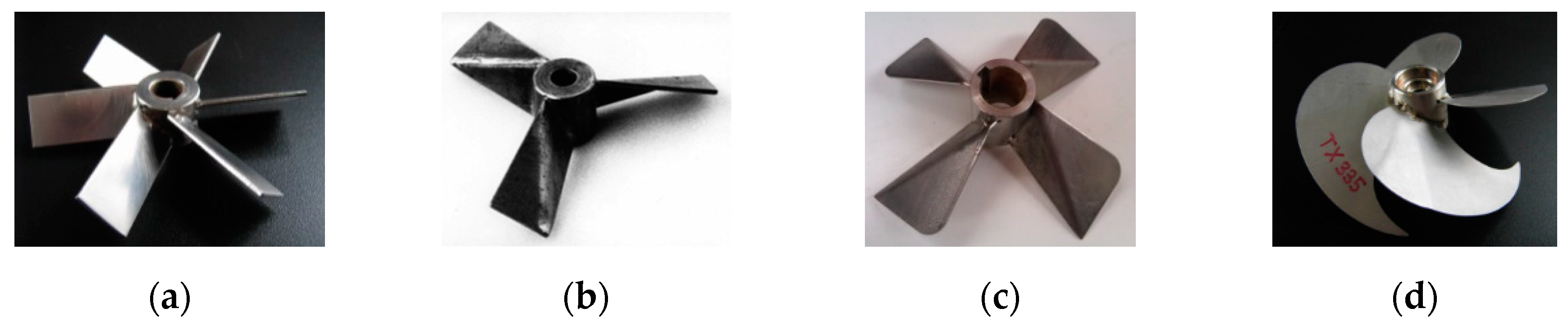
Design modifications of the blade shape consist of adjusting the surface of the blades and their folding or inclining. The angles of inclining or folding affect the pumping capacity of the impeller and the flow velocity field’s discharge from the rotor area of the impeller. Examples of developmental types of axial hydrofoil impellers are shown in
Figure 6.
Figure 6a shows a basic non-optimized type of stirrer with inclined rectangular blades (standard pitched six-blade turbine with pitch angle 45°). The simplest way to shape the blades is to diagonally fold them (see
Figure 6b). It can be seen from
Figure 6b that only folding the blades results in a uniform axial outflow of liquid from the agitator with a piston speed profile. The next step is to increase the area of the blade and adjust its shape, which will not only direct the flow, but also improve other process characteristics, e.g.,
Figure 6c shows a turbine designed by the author [
11], and
Figure 6d shows a turbine designed by Techmix s.r.o. The shaping of the blades is carried out either on the basis of operational experience or on the basis of experimental monitoring of the processes taking place in the agitated batch (e.g., homogenization, particle suspension, dispergation) and the velocity field in the agitated batch (e.g., by LDA or PIV), or using CFD simulations. Flow in the agitated batch with hydrofoil impellers is described in more detail in [
6,
12,
13].
The processes taking place in the agitated batch are affected not only by the flow and circulation, but also by the pumping and the circulation efficiency of the agitator. For this reason, based on the measurement of the velocity field in the agitated batch by LDA, the hydraulic efficiencies of a number of standardized and hydrofoil impellers used for homogenization and particle suspension, especially in the turbulent flow region, were evaluated. The pumping and the circulation efficiency of these agitators were compared on the basis of their hydraulic efficiency, defined according to Equations (14) and (15). From the summary of the results given in
Table 1 and
Table 2, it is evident that all the hydrofoil impellers show higher pumping efficiency than agitators with inclined unshaped blades.
The shape of the velocity profile at the discharge of the hydrofoil impellers, the directed flow of liquid in the agitated batch and their high pumping efficiency predetermine these impellers to increase the efficiency of the homogenization and particle suspension processes, especially with regard to minimizing energy requirements.
2.5. Multistage Axial Flow Agitator
To ensure, in particular, the homogeneity of the agitated batch, in the case of mixing in lean vessels (
H/
D > 1) or when mixing non-Newtonian fluids, it is expedient to install more agitators on a common shaft; these are called multistage impellers. Each agitator ensures pumping and circulation of the batch in its immediate vicinity, and due to the transfer of momentum between these partial circulation loops, the entire agitated batch is flowing and circulating, which is necessary for homogenization. An overview of the use of multistage impellers and the optimization of their configuration is given in [
14].
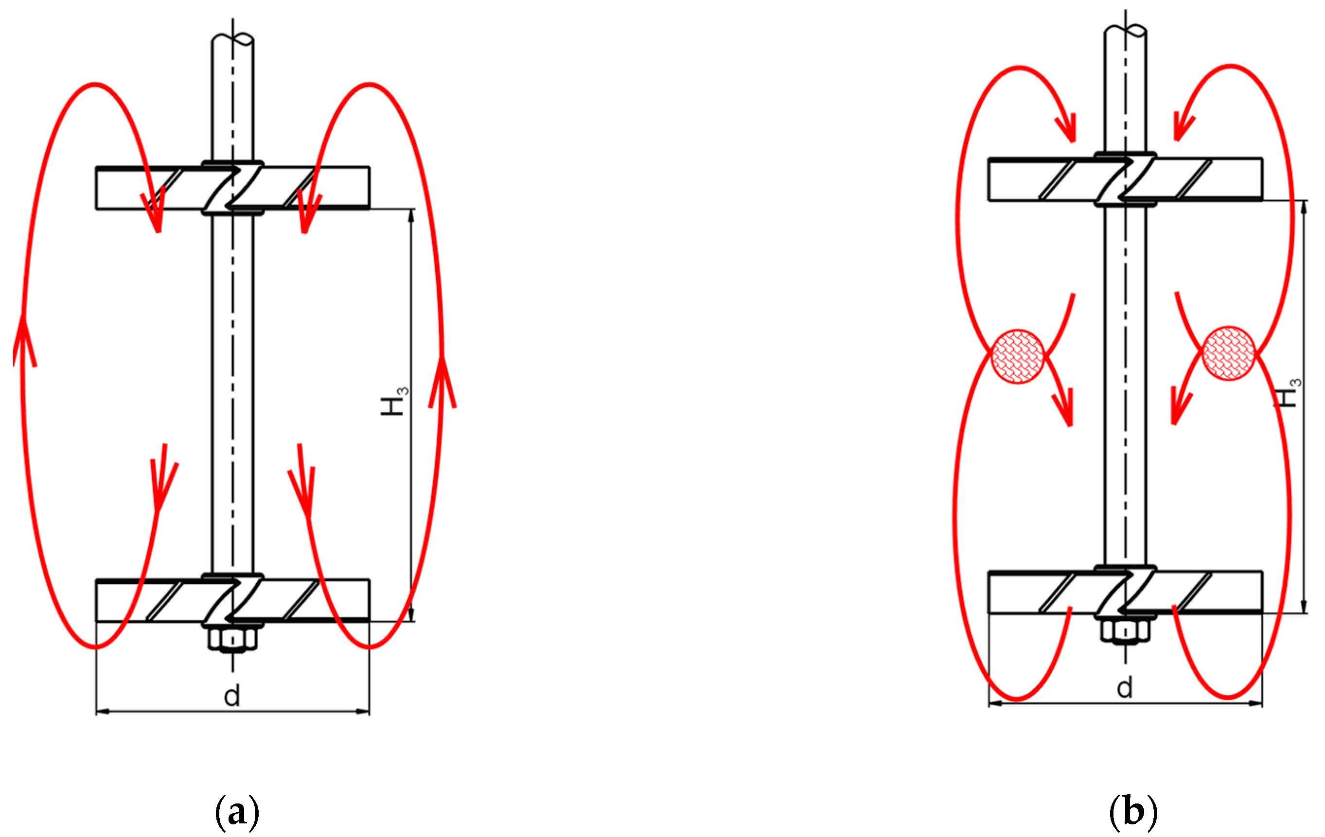
In lean vessels, the recommended distance between individual agitators is in the range of one to two times the agitator diameter (
H3/
d = 1–2). When at a distance equal to approximately twice the agitator diameter, the circulation zones of individual agitators are not affected, but there is sufficient momentum transfer between them. Further increase of the mutual distance of the agitators (
H3/
d > 2) leads to the separation of individual circulation loops and the formation of unmixed “dead” zones between them. Conversely, with an agitator distance less than
H3/
d < 0.75, only one circulation loop is formed in the agitated batch with axial flow impellers (see
Figure 7a). In this case, all of the liquid in the discharge from the upper agitator is sucked by the lower agitator, and the system acts as pumps connected in a series. When the distance of the agitators is increased in the range
H3/
d = 0.75–1.25, the circulation loops gradually separate, with an increased energy dissipation at the point of their collision (
Figure 7b), which results in the throttling of the agitators and the reduction of their hydraulic efficiency. These conclusions follow from the dimensionless pumping capacities of the agitators forming two arrangements of multistage impellers, mentioned in
Table 3 [
15].
3. Homogenization Effects of Agitators
3.1. Homogenization in the Agitated Batch
A theoretical description of the homogenization process would require a simultaneous solution of the Navier–Stokes equation and basic equation for mass transfer. When mixing mutually miscible liquids, the blending is usually controlled by convective and turbulent diffusion. Molecular diffusion in liquids is relatively slow, and in mixed systems with good circulation its effect can usually be neglected. Based on the inspection analysis [
4] of the equations described above, in geometrically similar mixing equipment, with a constant degree of homogeneity in the agitated batch the dimensionless homogenization time depends on the modified Reynolds number
Re used in mixing theory:
In the area of creeping flow, in addition to that for fully developed turbulent flow, Equation (18) takes the form:
The homogenization of the agitated batch occurs due to the circulating flow. The required number of circulations also depends on the required degree of homogeneity. The blending (homogenization) time can therefore be expressed as the product of the required number of circulations and the circulation time:
and in dimensionless form:
The number of agitated batch circulations required to achieve the desired degree of homogeneity can be expressed in the turbulent flow region with knowledge of the total dimensionless flow in the mixed batch
NQT and the dimensionless homogenization time
nt, in the form [
16]:
It is necessary to take into account not only the power input, but also the homogenization time when choosing a suitable type of agitator. A low-power agitator that exhibits a long homogenization time may be as unsuitable as an agitator that homogenizes the agitated batch in a very short time, but at a disproportionately high power input. It follows that the energy needed for achieving the required degree of homogeneity must be taken into account when comparing different types of agitators. In the turbulent flow region, it is possible to express this energy according to [
4] with knowledge of the power number of the agitator
Po in a dimensionless form:
A number of methods for determining the degree of homogeneity (decolorization, conductivity) are used in the experimental determination of the mixing time required for the homogenization of the agitated batch. A detailed overview of the principles of these methods is summarized in [
10]. The homogenization times thus obtained are evaluated in the form of a dimensionless homogenization characteristic, according to Equation (18) or (19), in accordance with [
17,
18,
19].
3.2. Geometric Configuration of the Mixing Equipment
3.2.1. Use of Baffles in a Cylindrical Vessel
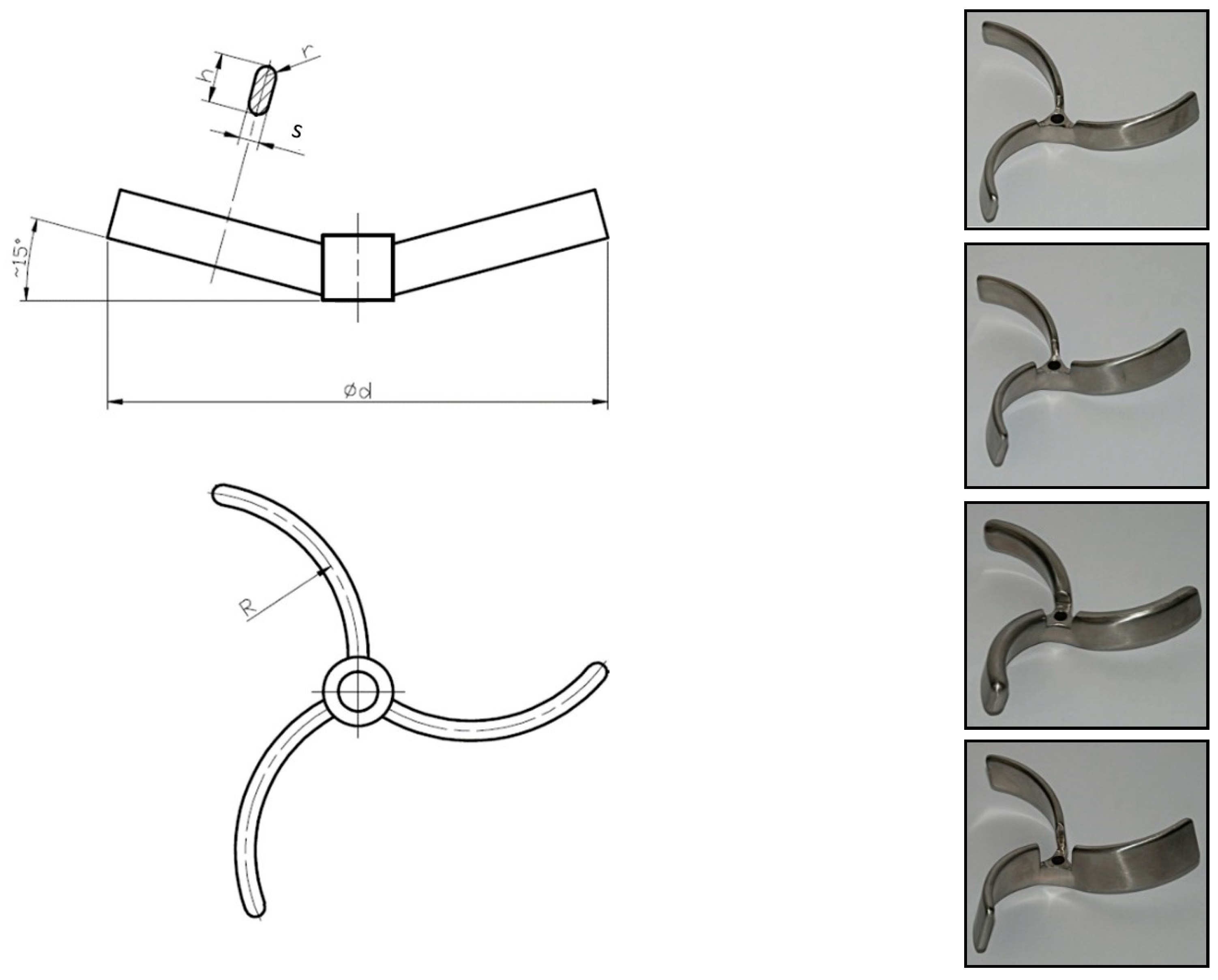
As already mentioned, the installation of the inserts in a cylindrical vessel in the form of baffles has a significant effect on the character of the flow in the agitated batch. Enhancing the axial flow in the agitated batch results in a significant reduction in homogenization time. From the comparison of the homogenization time and, in particular, the energy needed for achieving the required degree of homogeneity in the agitated batch, given in
Table 4 for agitators with curved blades (
Figure 8 and
Figure 9), it is evident that the use of baffles (radial and special finger—
Figure 8) will reduce the energy intensity of the process by several orders of magnitude. In the case of a vessel without baffles, it is energetically more advantageous to use agitators of larger diameters.
3.2.2. Shape of the Blades and Geometry Configuration of Agitators
The homogenization of the agitated batch occurs because of the circulation flow caused by the pumping effects of the agitators, which depends on the shape of the blades and the geometric configuration of the agitator. The hydraulic characteristics of the agitators (
Table 1 and
Table 2) were supplemented by the experimentally determined homogenization characteristics of various types and configurations of the agitators, mentioned in
Table 5. To achieve the required degree of homogeneity, radial impellers (
Table 4,
Table 5 and
Figure 10) have a higher energy consumption compared to axial flow impellers. From a comparison of the energy requirements of the homogenization of the agitated batch, it can be seen that the hydrofoil impellers, while maintaining the same geometric parameters, show lower energy requirements compared to impellers with inclined blades. The relative diameter of the impeller
D/
d and its relative height above the bottom
H2/
d have a significant effect on the energy intensity. These parameters affect the pumping and the circulation effects of the impellers.
The evaluation of homogenization measurements, taking into account the pumping and the circulation effects of impellers [
16,
21], shows that the number of agitated batch circulations required to achieve 98% homogeneity is
i = 3–4 for all measured axial flow impellers in a cylindrical vessel with radial baffles. In addition, this extensive set of homogenization characteristics of agitators in the turbulent flow region was evaluated together with the power characteristics, in the form:
For all measured configurations, the value of the constant mentioned in Equation (24) oscillated around 5.2 with a standard deviation of ±10%, which confirmed the approach published in [
23]. It follows from this approach that it is possible to determine the dimensionless homogenization time in the turbulent flow region in a cylindrical vessel with radial baffles approximately with knowledge of the power number
Po of the used agitator, according to Equation (24).
4. Suspension Efficiency of Impellers
4.1. Description of the Particle Suspension Development
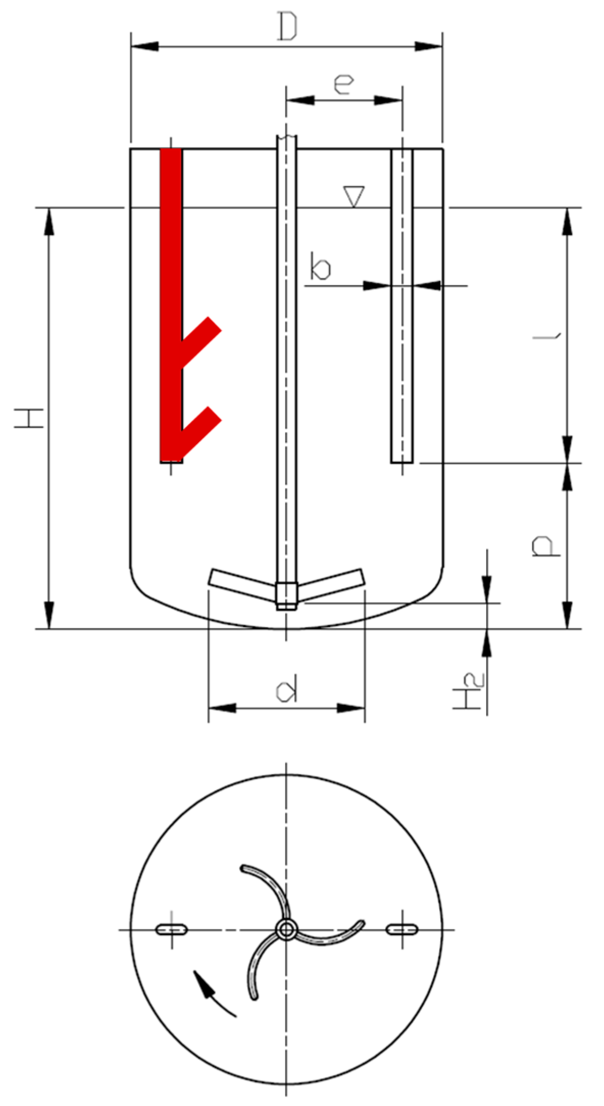
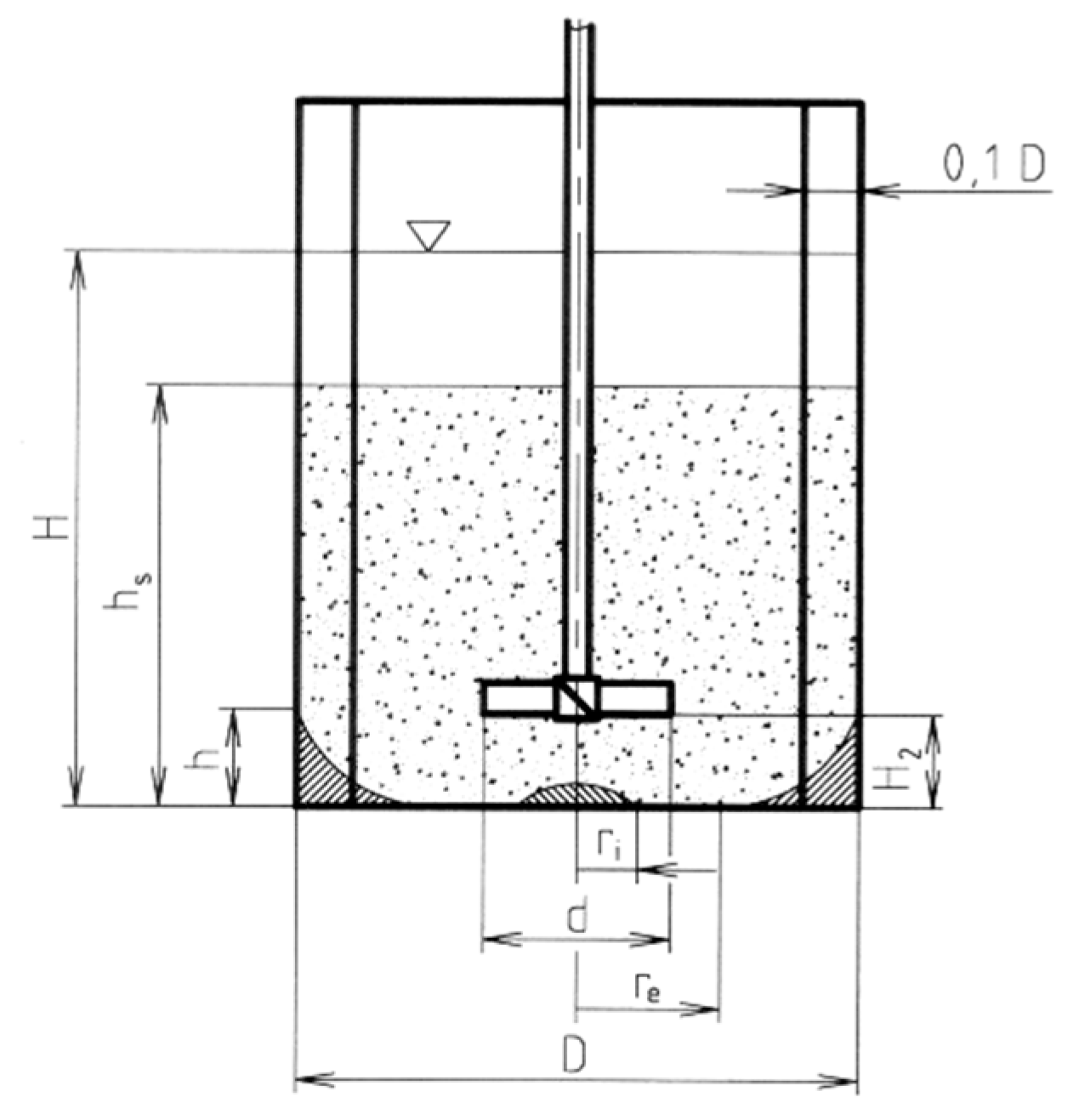
The description of the suspension of sedimented particles means monitoring the arrangement of the layer of unsuspended particles at the bottom of the vessel, in addition to the interface of the cloud of suspended particles and pure liquid in the agitated batch characterized by its height hs, depending on the impeller speed. As the agitator speed increases, the particles gradually take a just-suspended state. A ring without settled particles is formed at the bottom of the vessel. This ring separates the layer of particles settled under the impeller, characterized by its radius ri, and the layer of particles settled at the wall of radius re and height at the wall h. With a further increase in the impeller speed, the ring of the cleaned bottom grows until the just-suspended state is reached for all particles; when the radius of the layer of particles settled on the bottom below the impeller is zero ri = 0, the radius of the layer of particles settled on the bottom at the wall is half the diameter of the vessel re = D/2, and the height of this layer at the vessel wall is also zero h = 0.
While in the just-suspended state, all of the solid phase is dispersed in the liquid, but with an unequal local concentration that decreases towards the surface. As the impeller’s speed is further increased, the homogeneity of the suspension gradually increases. The maximum impeller speed is then usually limited by the entrainment of air from the space above the surface into the agitated batch. These monitored parameters are shown in
Figure 11.
Particles located before the just-suspended state, from the layer of settled particles at the bottom, i.e., z = 0 (r = ri, r = re) and z = h (r = D/2), and the particles located at the dead level at the cloud interface of the formed suspension and the pure liquid, i.e., z = hs, have zero velocity. The vertical component of the force of the flow liquid acting on the particles is in balance with the gravity force reduced by the buoyancy force.
For geometrically similar mixing equipment, based on the inspection analysis [
24] of basic hydrodynamic equations in dimensionless form, together with the force equilibrium with respect to the number of particles, and also considering the conditions for the dimensionless coordinates of the boundary layer of settled particles and for the created suspension, the following conclusions can be made:
and
In the region of large values of the modified Reynolds number, the influence of viscous forces can be neglected, and the arrangement of the layer of particles and suspension according to Equations (25)–(28) will not be a function of the modified Reynolds number Re.
4.2. Just-Suspended State of Solid Phase
The just-suspended state of the solid phase is defined as the state in which all of the solid particles are dispersed in the agitated liquid, i.e., no particles remain in contact with the bottom of the vessel (no particles lie without motion at the bottom) and all are completely surrounded by liquid [
25]. This achieves the maximum interfacial area, which is required, for example, in mass transfer. The impeller speed required to achieve the just-suspended state is called the just-suspended speed.
To keep the solid phase particles in the just-suspended state, it is necessary that the vertical component of the force by which liquid acts on these particles is greater than the gravitational force as reduced by the buoyancy force. For geometrically similar mixing equipment, based on inspection analysis according to [
26], basic hydrodynamic equations in dimensionless form and this force balance, with regard to the number of particles in the just-suspended state, the following conclusions can be drawn:
In the region of large values of the modified Reynolds number, the influence of viscous forces can be neglected, and therefore it can be assumed that the liquid acts on the particles only by the force of dynamic pressure. In the turbulent flow region, Equation (29) takes the form:
The dependence of the modified Froud number
Fr′ on the dimensionless particle size
dp/D and the mean volumetric concentration of the solid phase
cv according to Equation (30) is called the suspension characteristic, and in this form it is possible to evaluate the experimental determination of the impeller speed needed to achieve or maintain the just-suspended state of the solid phase in the turbulent flow region. The mechanism of the suspension of relatively small particles is different from that of relatively large particles. For this reason, it is necessary to distinguish the evaluation of experimental data for these two areas. In the work [
26], it was shown that the suspension characteristics for individual volumetric concentrations of the solid phase can be expressed by the power law:
with coefficients
C1 and exponent
γ1 for relatively small particles, or
C2 and exponent
γ2 for relatively larger particles (usually
γ2 = 0).
The coefficients
Ci and
γi of the Correlation (31) expressing the suspension characteristic of the impeller depend on the mean volumetric concentration of the solid phase
cv. A mathematical description of this dependence was proposed and verified via experimental data by [
26] in the form:
and
The impeller’s speed required to achieve the just-suspended state of solid phase, i.e., the minimum impeller speed in the operating equipment for suspension mixing, can be determined by calculation with Equation (31), which is confirmed by the scale-up results according to [
27]. The values of the coefficients in Equations (31)–(33), determined experimentally for geometrically similar models of mixing equipment with different geometric configurations of impellers, are given, e.g., in [
28].
The suspension efficiency of the impellers is assessed on the basis of the power input of the impeller required to achieve the just-suspended state of the particles. For this purpose, a dimensionless criterion is proposed [
29], which emerges by excluding the impeller’s speed at the just-suspended state and the impeller’s diameter from the dimensionless criteria already defined by the modified Froud number
Fr′ and the power number
Po in the form:
4.3. Geometric Configuration of the Equipment for Mixing Suspensions of Sedimented Particles
A detailed analysis of the optimization of the geometric configuration of equipment for mixing sedimented particles is given in a summary work [
30], which expands the work [
31], and therefore only summary conclusions supplemented by the latest results will be given below.
4.3.1. Vessel of the Mixing Equipment
Mixing equipment with a cylindrical vessel and a centrically positioned mechanical rotary agitator are most often found in industry. In the case of apparatuses loaded only with the hydrostatic pressure of the agitated batch, large cylindrical vessels with a flat bottom, or smaller vessels with a conical bottom provided with a discharge, are used. Pressure apparatuses are always, from a strength point of view, equipped with a cylindrical vessel with a dished bottom.
The experimental monitoring of the suspension in a vessel with a flat bottom shows that its biggest disadvantage lies in the sharp transition between the flat bottom and the wall of the vessel, in which the mixing intensity decreases and settled particles remain, resulting in a significant increase in just-suspended impeller speed and thus power required to achieve the just-suspended state. This disadvantage can be eliminated by modifying the construction of the vessel bottom, consisting in removing the sharp transition between the bottom and the wall of the vessel or in modifying the space of the bottom under the agitator. Although the conical transition will significantly reduce the impeller speed and the power of the impeller required for the just-suspension state of the particles compared to a flat-bottomed vessel, a vessel with a dished bottom is the most energy-efficient for a wide range of particle sizes and concentrations in suspension [
32,
33].
4.3.2. Use of Baffles in a Cylindrical Vessel
When mixing in cylindrical vessels with a flat or dished bottom, the character of the flow of the agitated batch, and thus also the suspension of particles, is influenced by the use of inserts in the vessel in the form of variously shaped and placed baffles. In the case of mixing in a vessel without baffles in the region of turbulent flow, the agitated batch in the vessel flows predominantly in a tangential direction, and the layer of particle sediment at the bottom of the apparatus only rotates and does not homogenize in its entire volume. For these reasons, it is necessary to install the baffles in the vessel and thus strengthen the axial flow of the suspension, thereby achieving better homogeneity. Currently, different types, shapes and locations of baffles in the vessel are used depending on the design of the apparatus (e.g., flat radial, arrow, tubular, finger). Adjusting the shape and position of the baffles installed in the mixing vessel does not lead to significant energy savings, but due to the elimination of dead flow zones, all these adjustments of standard baffles are advantageous, particularly for operational and technological reasons (e.g., uniform product quality, and the good cleanability and sanitation of the apparatus).
4.3.3. Shape of Blades and Geometric Configuration of the Impeller
The choice of the type and geometrical arrangement of the rotary agitator affects not only the course of the particle suspension, but also the energy required for the suspension of the solid phase. High-speed impellers of various constructions are most often used for mixing suspensions, predominantly causing an axial flow in the agitated batch in the vessel. Based on many experiments [
30], it can be concluded that in terms of the power of the impeller required to achieve the just-suspended state, it is appropriate to use an axial flow impeller to pump liquid towards the bottom of the vessel. The optimum height of the lower edge of the blades of the axial flow impellers above the bottom of the vessel ranges from one-third to three-quarters of the diameter of the impeller
H2/
d = 1/3–3/4, and the optimal ratio of the diameter of the vessel to the diameter of the impeller is around the value
D/
d = 3. In some special constructions of mixing equipment (e.g., enameled apparatuses), the radial impellers are also used for suspension. Three-bladed agitators, with curved blades in the configuration according to
Figure 8, are energetically and structurally advantageous for these apparatuses, but in these cases it is necessary to pay increased attention to the appropriate use of baffles, which at least partially direct the flow in the axial direction.
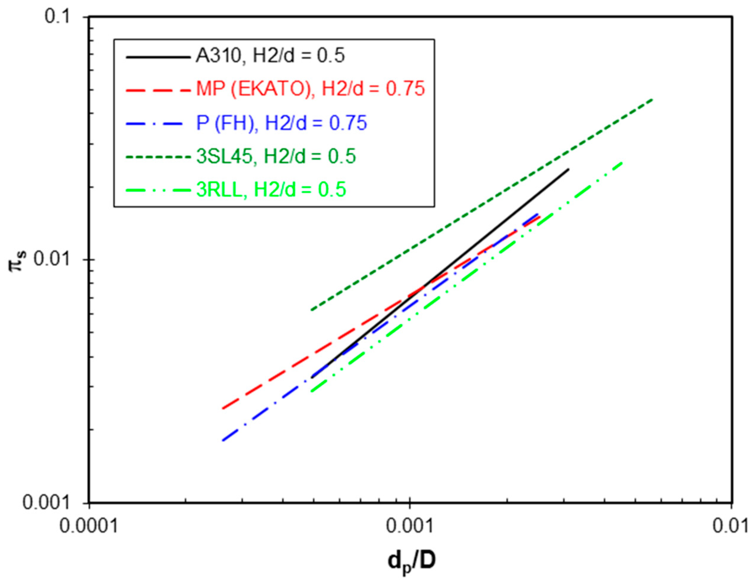
A comparison of the suspension efficiency of a large number of axial flow impellers shown in
Figure 12,
Figure 13 and
Figure 14 shows that all impellers with shaped blades (axial hydrofoil) have significantly lower energy requirements for suspension than standard impellers with inclined blades. All hydrofoil impellers (with folded and large-shaped blades) show practically the same suspending efficiency when compared based on their energetically optimal height above the bottom. In addition, an impeller with diagonally folded blades, which has a significantly simpler geometric blade shape, has practically the same, or even slightly lower, energy requirements for suspension compared to hydrofoil impellers with complicated blade shapes. Moreover, its efficiency is practically the same regardless of the number of blades.
A frequent application of mixing operations in industry is the mixing of suspensions with a high content of solid phase in a liquid. In equipment for the mixing of concentrated suspensions, it is often necessary to ensure, in addition to achieving the just-suspended state of the suspension particles, the sufficient homogeneity of the suspension in the agitated batch, which can be achieved using multistage axial flow impellers. From the point of view of the power of the multistage impellers required to achieve the just-suspended state of the particles, or required to keep the particles in this state, the most advantageous appear to be multistage impellers with the largest distance between the impellers, i.e.,
H3/
d = 1.25, which corresponds to the conclusions given in
Section 2.5. At the same time, the power of these multistage impellers does not depend on the number of their blades [
35].
4.4. Geometric Configuration of the Equipment for Mixing Suspensions of Floating Particles
In industry, there are suspensions of particles lighter than liquid, i.e., particles floating at the liquid level (floating particles) (e.g., sludge treatment, fermentation processes, polymerization reactions and production of colors, paper, cellulose, powders and food). Various configurations of mixing equipment with axial flow impellers are used in industry to mix these suspensions.
Three commonly recommended configurations of this equipment were tested in the work [
36]—a vessel with four radial baffles, a vessel with one baffle placed against an eccentrically placed impeller, and a vessel without baffles with an eccentrically placed impeller. The devices were equipped with standard impellers with inclined blades, in addition to axial hydrofoil impellers pumping to the bottom of the vessel or to the batch surface. From a comparison of the configurations shown in
Figure 15, it is clear that the lowest power required for suspension formation of the floating particles (i.e., to remove the particles from the surface and homogenize them) is achieved in a vessel with four radial baffles and a centrally located axial flow impeller pumping towards the surface and placed one-third of the impeller diameter below the surface, i.e.,
H2/
d = 2/3. These conclusions correspond to the results reported in [
37]. Analogous to mixing sedimented particles, the most energetically preferred are impellers with shaped blades (hydrofoil) operating in the above-mentioned configuration.
4.5. Geometric Configuration of the Equipment for Mixing Heterogenous Suspensions
When mixing dispersions, heterogeneous suspensions are encountered in industry consisting of particles of various sizes and compositions, which must be considered when choosing a suitable system geometry and determining the speed and power of the impeller. Sludges and substrates in biotechnological processes have strongly heterogeneous composition, i.e., they contain sedimented and floating particles. An example of a substrate in an agitated fermenter in biogas production is shown in
Figure 16.
In the case of heterogeneous suspensions comprising particles of the same or similar density but different particle sizes, experiments have shown that it is possible to disregard the particle size and the concentration of the particles in the largest fraction of the solid phase when determining the impeller speed required to achieve the just-suspended state of the particles. The energetically optimal configuration of mixing equipment for these suspensions can then be selected according to the recommendations in
Section 4.3.
A more complicated situation occurs when mixing heterogeneous suspensions formed by particles of different size and composition, particularly suspensions containing both floating and sedimented particles. In such a case, it is necessary to ensure that sedimented particles are in the just-suspended state, floating particles are entrained from the surface, and, at the same time, the suspension is homogenized evenly throughout the volume. A number of configurations of mixing equipment, differing in the location, type and shape of the impeller blades, the direction of liquid pumping and the use of multistage impellers, were tested experimentally. When using a separately working impeller that pumps the liquid towards the bottom according to the configuration recommended in
Section 4.3, the particles were removed from the surface with great difficulty, and only after achieving high impeller speeds, although the just-suspended state of sedimented particles was ensured. In the case of using impellers which pump the liquid towards the liquid level according to the configuration recommended in
Section 4.4, the opposite situation occurred. In both cases, the homogeneity of the suspension was not ensured, as the sedimented particles remained at the bottom of the agitated batch and the floating particles remained close to the liquid level. For this reason, the use of a multistage impeller has been proposed [
38], wherein the lower impeller pumps to the bottom and ensures the just-suspended state of sedimented particles, and the upper impeller pumps towards the liquid level, thereby entraining the floating particles. Due to the transfer of momentum between the lower and upper circulation loop, sedimented and floating particles are homogenized throughout the volume. In addition, this configuration exhibits minimal energy requirements for the suspension and homogenization of the agitated batch; the specific power needed for the formation of a homogenous suspension is from 5× to 10× lower than that of the standard configurations mentioned above, i.e., single up or down pumping impeller [
11]. A scheme of the designed configuration of the equipment is shown in
Figure 17.
4.6. Geometric Configuration of the Equipment for Mixing Highly Concentrated Fine-Grained Suspensions
In cases where the highly concentrated suspension consists of fine particles with dimensions from μm to tens of μm, there is a change in the flow properties of the suspension, which begins to exhibit non-Newtonian visco-plastic behavior. When mixing non-Newtonian suspensions with high-speed impellers, there is a danger that in areas remote from the impeller there is a low shear stress and thus a high apparent viscosity, and as a result, the liquid does not flow there. The flow occurs only at the impeller, where a well-mixed cavern is formed. The procedure for determining the size of the agitated cavern is given attention, for example, in [
39]. The design parameters of equipment for mixing these suspensions are thus determined to achieve circulation of the suspension throughout the batch, which can be achieved by a suitable geometric configuration of the mixing equipment.
Experiments testing a number of slow-speed and high-speed impellers (screw agitator with a draft tube, axial flow impellers, and various variants and arrangements of multistage impellers) and their configurations given in [
40] showed that to ensure the circulation of the agitated batch during the mixing of highly concentrated non-Newtonian visco-plastic suspensions, the most preferred are multistage impellers of larger diameters (
Figure 7). In this configuration, the power required to get the entire slurry to move sufficiently can be up to half that of a standard six-blade impeller when these impellers are correctly placed in the slurry.
5. Special Aspects of Mixing Equipment Design
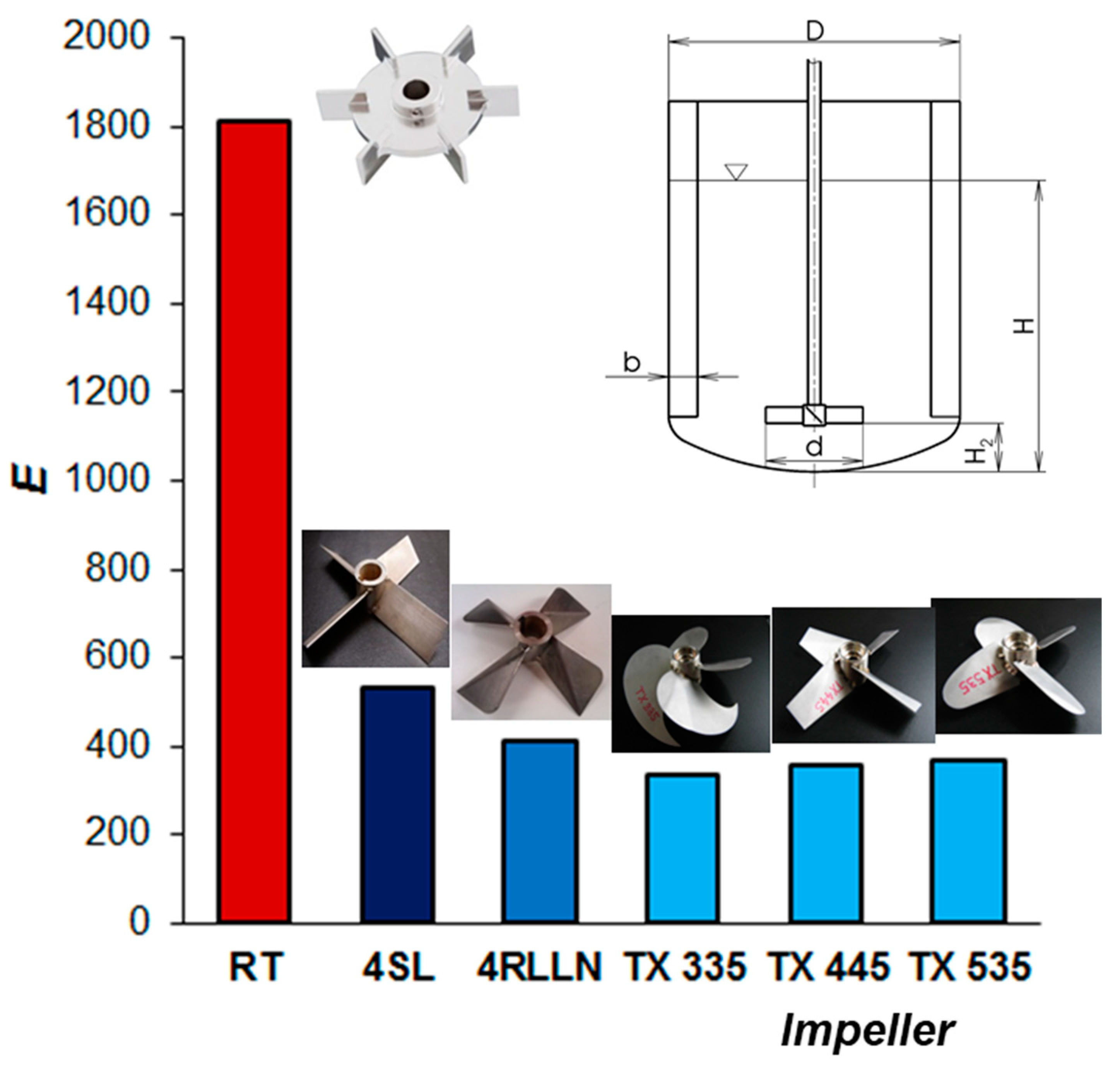
When designing mixing equipment, the configuration of the equipment must be chosen not only with regard to minimizing operating costs, but also based on the shape and material of functional parts of the equipment (agitator, shaft and vessel), and in terms of their strength characteristics, corrosion resistance and mechanical wear. In the chemical, food and pharmaceutical industries, equipment is often exposed to aggressive environments, where a suitable surface treatment, e.g., enameling, must be chosen to protect against corrosion and wear. From the point of view of the engineering production of such equipment, it is then necessary to take into account the adjustment of the geometry of the functional parts of the equipment (e.g., the necessity of removing all sharp transitions and edges by gradual rounding in the case of enameling). These modifications in the construction of the equipment significantly affect the character and intensity of the flow in the agitated batch, and thus the processes taking place in it. When comparing the energy requirements for homogenization and suspension, rounded-blade impellers showed energy requirements that were from 2× to 3× higher than those of standard (sharp) impellers (
Figure 18). This fact must be taken into account when designing, for example, enameled apparatuses, and it is not possible to use the process characteristics of agitators without rounding the edges to calculate the speed and the power of enameled rounded agitators.
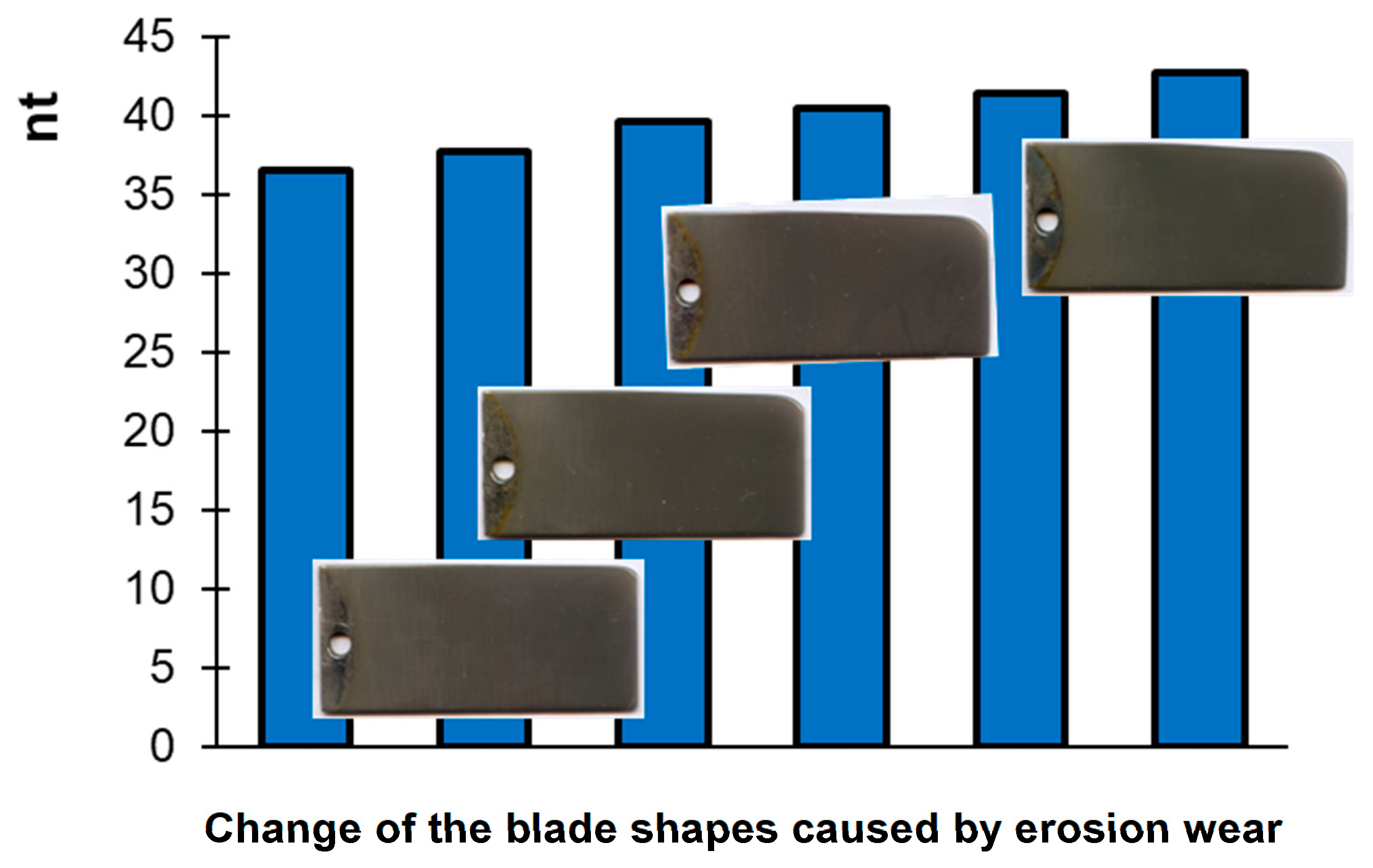
In the case where no modification of the equipment is made due to corrosion and mechanical wear, it must be taken into account that due to the effect of the environment on the agitator blades, shape or surface wear will occur. Shape wear of the agitator blades results in a change in the geometric shape of the agitator. As a result, its pumping efficiency decreases, and thus other process characteristics change [
41], which can lead to deterioration of product quality. An illustration of the changes in process parameters, in particular homogenization effects, caused by the shape erosive wear of the agitator blades is shown in
Figure 19. The photographs show the blade shape change of the impeller caused by the erosive impact of particles on the leading edge of the impeller blade during the mixing of industrial suspensions with hard particles. From
Figure 19, it is evident that growing blade wear significantly increases the dimensionless blending time. Surface wear of the impeller blades results in a reduction in their thickness, and thus in their strength. In extreme cases, they can also be destroyed, which results in putting the mixing equipment out of operation, with the consequent costs of maintenance and replacement of the impeller.
The degree of wear depends on the material of the blades and their surface treatment, and on their geometric shape and interaction with the particles. A detailed description of the influence of the material on the degree of blade wear is given in [
42].
6. Conclusions
In mixing purpose terms, the most common requirements are to homogenize the agitated batch and ensure suspension of the particles. These operations are sensitive to the hydrodynamic conditions in the agitated batch, which is an issue that has not yet been comprehensively solved from the point of view of plant construction. Based on an extensive set of experiments, it was shown how the flow in the agitated batch caused by the pumping and circulating effects of the agitators affects the parameters and energy efficiency of these processes in a manner depending on the geometric configuration of the mixing equipment. Such a comprehensive review allows the optimization of the design and arrangement of mixing equipment.
The shape of the velocity profile at the discharge of hydrodynamically optimized (hydrofoil) impellers, the directed flow of the agitated batch in a cylindrical vessel equipped with radial baffles and their high hydraulic efficiency predetermine these impellers to increase the efficiency of homogenization and suspension processes.
Subsequent experiments confirmed the use of hydrofoil impellers for the homogenization of the agitated batch, and their mixing of suspensions is more effective compared to standard impellers with inclined blades.
For mixing suspensions of sedimented particles, it is advantageous for these impellers to be placed in a vessel with radial baffles above the bottom, and for them to pump towards the bottom. Conversely, to draw down particles and ensure the suspension homogenization of floating particles, the impellers need to be placed below the liquid level and pump towards the liquid level.
When mixing highly concentrated, fine-grained or heterogeneous suspensions, from the point of view of ensuring the required homogeneity of the suspension and the energy intensity of the process, it is suitable to install a multistage impeller in a cylindrical vessel with baffles so as to ensure the necessary flow and circulation in the entire volume of the agitated batch.
In cases where it is necessary to adjust the shape of the blades, e.g., by rounding for enameled impellers, or in cases where the shape of the blades changes due to wear, it should be taken into account that this change in blade shape significantly affects the hydrodynamic parameters of the impellers, and thus the processes taking place in the agitated batch.
Author Contributions
Conceptualization, methodology, validation, formal analysis, investigation, resources, writing—original draft preparation, T.J.; writing and editing, D.J. All authors have read and agreed to the published version of the manuscript.
Funding
This work was supported by Ministry of Education, Youth and Sport of the Czech Republic under OP RDE grant number CZ.02.1.01/0.0/0.0/16_019/0000753 “Research centre for low-carbon energy technologies”.
Conflicts of Interest
The authors declare no conflict of interest.
| Nomenclature |
| Ai, Bi | coefficients of Equation (32) | [1] |
| b | baffle width | [m] |
| Ci | coefficients of Equation (31) | [1] |
| cv | mean volumetric concentration of solid phase | [1] |
| D | vessel diameter | [m] |
| d | agitator diameter | [m] |
| dp | mean volumetric particle diameter | [m] |
| d1 | diameter of upper impeller | [m] |
| d2 | diameter of lower impeller | [m] |
| E | dimensionless energy necessary to achieve the required degree of homogeneity | [1] |
| EP | impeller energetic efficiency | [1] |
| ET | impeller total energetic efficiency | |
| Fr′ | modified Froude number | [1] |
| g | acceleration due to gravity | [m·s−2] |
| H | height of the liquid level | [m] |
| H2 | impeller off-bottom clearance (measured from the lowest point on the blades) | [m] |
| H3 | distance between impellers for multistage configuration | [m] |
| h | height of the particle sediment layer at the wall | [m] |
| h | blade width | [m] |
| hs | height of the cloud of suspended particles | [m] |
| i | number of circulations of agitated batch | [1] |
| NQi | inducted flow rate criterion | [1] |
| NQP | flow rate criterion (flow number) | [1] |
| NQT | total flow rate criterion | [1] |
| n | impeller speed | [s−1] |
| n | normal vector | [1] |
| nt | dimensionless blending time | [1] |
| ncr | just-suspended impeller speed | [s−1] |
| P | power input of agitator | [W] |
| Po | power number | [1] |
| p | pressure | [Pa] |
| V | volume of agitated batch | [m3] |
| Qi | inducted volumetric flow rate in agitated batch | [m3·s−1] |
| QP | pumping capacity of impeller | [m3·s−1] |
| QT | total flow rate in agitated batch | [m3·s−1] |
| R | bending radius | [m] |
| Re | Reynolds number in mixing theory | [1] |
| r | radial coordinate | [m] |
| ri | outer radius of the particle sediment layer at the center of the vessel bottom | [m] |
| re | inner radius of the particle sediment layer at the vessel bottom | [m] |
| S | surface | [m2] |
| s | blade thickness | [m] |
| t | mixing time | [s] |
| tc | circulation time | [s] |
| u | velocity | [m·s−1] |
| velocity vector | [m·s−1] |
| x | coordinate | [m] |
| position vector | [m] |
| z | axial coordinate (measured along agitator shaft) | [m] |
| αi, βi | coefficients of Equation (33) | [1] |
| γi | coefficients of Equation (31) | [1] |
| ε | specific power | [W·m−3] |
| μ | dynamic viscosity | [Pays] |
| πs | dimensionless power consumption
necessary for particle suspension | [1] |
| ρ | liquid density | [kg·m−3] |
| ρsu | suspension density | [kg·m−3] |
| Δρ | solid–liquid density difference | [kg·m−3] |
| Lower index |
| ax. | axial component | |
| Upper index |
| *, + | dimensionless variables | |
| ~ | time—average value | |
| Abbreviations |
| 3SL24, 3SL35, 3SL45 | Pitched three-blade turbine with pitch angle α = 24°, 35° or 45° |
| 4SL, 6SL | Pitched four- or six-blade turbine with pitch angle α = 45° |
| 3RLL, 4RLL, 6RLL | Pitched three-, four- or six-blade turbine with diagonally folded blades |
| 3TL | Pitched cylindrical three-blade turbine |
| A310 | Hydrofoil impeller LIGHTNIN type A310 |
| MP(EKATO) | Marine propeller EKATO |
| P(FH) | Propeller designed by Anhalt University of Applied Sciences/Hochschule Anhalt (FH) |
| TX335, TX445, TX535 | Axial-flow hydrofoil impeller TECHMIX |
| 4RLLN | Axial-flow impeller with large-area diagonally folded blades [11] |
| RT | Six-blade Rushton Turbine |
References
- Seichter, P.; Pešl, L. Rotary Agitator Design—Science or routine? CHEMagazín 2005, 15, 8–11. (In Czech) [Google Scholar]
- Fořt, I. Chapter 14: Flow and turbulence in vessels with axial impellers. In Mixing, Theory and Practice, Vol. III; Uhl, V.W., Gerry, J.B., Eds.; Academic Press: New York, NY, USA, 1986. [Google Scholar]
- Goómez, C.; Bennington, C.P.J.; Taghipour, F. Investigation of the Flow Field in a Rectangular Vessel Equipped with a Side-Entering Agitator. J. Fluids Eng. 2010, 132, 051106. [Google Scholar] [CrossRef]
- Rieger, F.; Novák, V.; Jirout, T. Hydromechanical Processes II, 1st ed.; CTU Publishing House: Prague, Czech Republic, 2005; p. 167. (In Czech) [Google Scholar]
- Jirout, T. Mixing of Suspension. Ph.D. Thesis, Czech Technical University in Prague, Prague, Czech Republic, 2005; p. 113. (In Czech). [Google Scholar]
- Jirout, T.; Rieger, F.; Jembere, S. Pumping capacity of axial-flow impeller. In Proceedings of the 6th International Scientific Conference Mechanical Engineering, Bratislava, Slovakia, 23–24 October 2002; Vydavate’stvo STU: Bratislava, Slovak Republic, 2002; pp. 1–9. (In Czech). [Google Scholar]
- Medek, J.; Fort, I. Pumping effect of impellers with flat inclined blades. Collect. Czechoslov. Chem. Commun. 1979, 44, 3077–3089. [Google Scholar] [CrossRef]
- Wu, J.; Zhu, Y.; Pullum, L. The effect of impeller pumping and fluid rheology on solids suspension in a stirred vessel. Can. J. Chem. Eng. 2001, 79, 177–186. [Google Scholar] [CrossRef]
- Medek, J.; Fořt, I. Mixing efficiency in monitoring the volumetric flow of the liquid by agitator. Chem. Prům 1979, 29, 116–119. (In Czech) [Google Scholar]
- Paul, E.L.; Atiemo-Obeng, V.A.; Kresta, S.M. Handbook of Industrial Mixing: Science and Practice; John Wiley & Sons, Inc.: Hoboken, NJ, USA, 2003; p. 1377. [Google Scholar]
- Jirout, T.; Rieger, F. Axial agitator with large-areas broken blades. In Utility Model 23644; Industrial Property Office: Prague, Czech Republic, 2012. (In Czech) [Google Scholar]
- Kumaresan, T.; Joshi, J.B. Effect of impeller design on the flow pattern and mixing in stirred tanks. Chem. Eng. J. 2006, 115, 173–193. [Google Scholar] [CrossRef]
- Fořt, I.; Kysela, B.; Jirout, T. Flow characteristics of axial high speed impellers. Chem. Process. Eng. 2010, 31, 661–679. [Google Scholar]
- Gorate, P.R.; Beenackers, A.A.C.M.; Pandit, A.B. Multiple-impeller systems with a special emphasis on bioreactors: A critical review. Biochem. Eng. J. 2000, 6, 109–144. [Google Scholar]
- Jirout, T. Pumping Capacity of Pitched Blade Multi-Stage Impellers. Chem. Process. Eng. 2014, 35, 47–53. [Google Scholar] [CrossRef]
- Fořt, I.; Jirout, T.; Rieger, F.; Allner, R.; Sperling, R. Study of the Blending Efficiency of Pitched Blade Impellers. Acta Polytech. 2001, 41, 7–13. [Google Scholar]
- Kramers, H.; Baars, G.M.; Knoll, W.H. A comparative study on the rate of mixing in stirred tanks. Chem. Eng. Sci. 1953, 2, 35–42. [Google Scholar] [CrossRef]
- Procházka, J.; Landau, J. Homogenization of miscible liquids by rotary impellers. Collect. Czech. Chem. Commun. 1961, 26, 2961–2974. [Google Scholar] [CrossRef]
- Khang, S.J.; Levenspiel, O. New scale-up and design criteria for stirrer agitated batch mixing vessels. Chem. Eng. Sci. 1976, 31, 569–677. [Google Scholar] [CrossRef]
- Jirout, T.; Krejčová, P.; Moravec, J. Process Characteristics of Agitator for Enameled Apparatuses; Research Report; CTU in Prague: Prague, Czech Republic, 2013; p. 27. [Google Scholar]
- Fořt, I.; Jirout, T. A study on blending characteristics of axial flow impellers. Chem. Process. Eng. 2011, 32, 311–319. [Google Scholar] [CrossRef] [Green Version]
- Rieger, F.; Jirout, T.; Kuncewicz, C.; Ceres, D. Homogenization and suspension production with a four-blade impeller of a new construction. Przem. Chem. 2013, 92, 508–511. [Google Scholar]
- Grenville, R.K.; Nienow, A.W. Blending in miscible liquid. In Industrial Mixing. Science and Practice; Paul, E.L., Otiemo-Obeng, V.A., Kresta, S.M., Eds.; Wiley Interscience: New York, NY, USA, 2003; pp. 507–542. [Google Scholar]
- Jirout, T.; Rieger, F. Course of particle suspension with axial-flow impeller. In Proceedings of the 29th International Conference of Slovak Society of Chemical Engineering, Tatranske Matliare, Slovakia, 27–31 May 2002; Slovenská Společnost Chemického Inženýrství: Bratislava, Slovak Republic, 2002; pp. 1–8. [Google Scholar]
- Zwietering, T.N. Suspending of solid particles in liquid by agitators. Chem. Eng. Sci. 1958, 8, 244–253. [Google Scholar] [CrossRef]
- Rieger, F. Effect of particle content on agitator speed for off-bottom suspension. Chem. Eng. J. 2000, 79, 171–175. [Google Scholar] [CrossRef]
- Jirout, T.; Rieger, F. Scale-up of Mixing Equipment for Suspensions. Chem. Process. Eng. 2009, 30, 359–367. [Google Scholar]
- Jirout, T.; Rieger, F. Impeller design for mixing of suspensions. Chem. Eng. Res. Des. 2011, 89, 1144–1151. [Google Scholar] [CrossRef]
- Rieger, F. Efficiency of agitators while mixing of suspensions. In Proceedings of the 6th Polish Seminar on Mixing, Zakopane, Poland, 14–15 September 1993; Politechnika Kraków: Kraków, Poland, 1993; pp. 79–85. [Google Scholar]
- Jirout, T. Particle Suspension in Mixing Equipment—Optimization of Equipment Design. Habilitation Lecture; Czech Technical University in Prague: Prague, Czech Republic, 2007; p. 27. (In Czech) [Google Scholar]
- Kasat, G.R.; Pandit, A.B. Review on Mixing Characteristics in Solid-Liquid and Solid-Liquid-Gas Reactor Vessels. Can. J. Chem. Eng. 2005, 83, 618–643. [Google Scholar] [CrossRef]
- Jirout, T.; Rieger, F. Effect of bottom treatments on the suspending effects of a pitched six-blade turbine agitator. In Proceedings of the 46th Konference Chemického a Procesního Inženýrství CHISA ’99, Srní, Vzech Republic, 18–21 October 1999; Procesní Inženýrství Ing. J. Novosad: Praha, Czech Republic, 1999; pp. 1–9. (In Czech). [Google Scholar]
- Moravec, J.; Jirout, T.; Rieger, F. Effect of Vessel Bottom Shape on Particle Suspension with High Concentrated Suspensions. In Proceedings of the 12th European Conference on Mixing, Bologna, Italy, 27–30 June 2006; AIDIC Servizi, S.r.l.: Milano, Italy, 2006; pp. 265–272. [Google Scholar]
- Rieger, F.; Jirout, T.; Ceres, D.; Seichter, P. Effect of Impeller Shape on Solid Particle Suspension. Chem. Process. Eng. 2013, 34, 139–152. [Google Scholar] [CrossRef] [Green Version]
- Jirout, T.; Rieger, F.; Procházka, J. Mixing of High Concentrated Suspensions—Applications of Multistage Impellers. In Proceedings of the XIV Celostátní Konference Míchání a Míchací Zařízení, Čerpadla, Ucpávky a Těsnění “Míchání 2006”, Brno, Czech Republic, 21–26 September 2006; Česká Společnost Chemického Inženýrství: Brno, Czech Republic, 2006; pp. 1–8. (In Czech). [Google Scholar]
- Svačina, O.; Jirout, T. The Effect of the Stirred Vessel Geometry Arrangement on the Drawdown of Floating Particles. In Procesní a Zpracovatelská Technika 2012 [CD-ROM]; CTU in Prague: Praha, Czech Republic, 2012; pp. 1–16. (In Czech) [Google Scholar]
- Karcz, J.; Mackiewicz, B. Suspending of floating solids in an agitated vessel. Chem. Process. Eng. 2006, 27, 1517–1533. [Google Scholar]
- Jirout, T.; Rieger, F. Mixing device for homogenization of heterogenic suspensions. In Utility Model 26644; Industrial Property Office: Prague, Czech Republic, 2014. (In Czech) [Google Scholar]
- Wichterle, K.; Wein, O. Treshold of mixing on non-Newtonian liquids. Int. Chem. Eng. 1981, 21, 116–120. [Google Scholar]
- Moravec, J.; Jirout, T.; Rieger, F.; Krátký, L. Mixing system for highly concentrated fine-grained suspensions. Pol. J. Chem. Technol. 2009, 11, 52–56. [Google Scholar] [CrossRef] [Green Version]
- Fořt, I.; Jirout, T. The relation between the rate of erosion wear of pitched blade impeller and its process characteristics. Chem. Eng. Res. Des. 2011, 89, 1929–1937. [Google Scholar] [CrossRef]
- Fořt, I.; Jirout, T.; Cejp, J.; Čuprová, D.; Rieger, F. Study of erosion wear of pitched blade impellers in a solid-liquid suspension. Chem. Process. Eng. 2005, 26, 437–450. [Google Scholar]
© 2020 by the authors. Licensee MDPI, Basel, Switzerland. This article is an open access article distributed under the terms and conditions of the Creative Commons Attribution (CC BY) license (http://creativecommons.org/licenses/by/4.0/).


