Article

3D Integrated Modeling of Supersonic Coherent Jet Penetration and Decarburization in EAF Refining Process

Center for Innovation through Visualization and Simulation (CIVS), Purdue University Northwest, 2200 169th Street, Hammond, IN 46323, USA
*
Author to whom correspondence should be addressed.
Processes 2020, 8(6), 700; https://doi.org/10.3390/pr8060700
Submission received: 25 May 2020 / Revised: 11 June 2020 / Accepted: 13 June 2020 / Published: 17 June 2020
(This article belongs to the Special Issue Process Modeling in Pyrometallurgical Engineering)

Abstract

:
The present study proposes a complete 3D integrated model to simulate the top-blown supersonic coherent jet decarburization in the electric arc furnace (EAF) refining process. The 3D integrated model avoids the direct simulation of the supersonic coherent jet interacting with the liquid steel bath and provides a feasible way to simulate the decarburization in the liquid steel-oxygen two-phase reacting flow system with acceptable computational time. The model can be used to dynamically predict the details of the molten bath, including 3D distribution of in-bath substances, flow characteristics and bath temperature and provide a basis for optimizing the decarburization rate or other required parameters during the refining process.

1. Introduction

Electric arc furnace (EAF) steelmaking featuring high efficiency and energy saving has become one of the major steelmaking methods in the world. The steel refining stage is seen as a final period to improve the thermal homogenization of the bath and adjust the metallurgical parameters of the steel grade. During this period, oxygen injection is desired to help to stir the molten bath, remove impurities and further improve the quality of the liquid steel. In the 1990s, Praxair, Inc. introduced the supersonic coherent jet technology (Cojet®) for oxygen injection in EAF [1], which significantly improves the jet performance and makes the jet to have deeper penetration depth, less splashing and, most importantly, more oxygen delivered to the molten bath. Therefore, this technology has been widely-used in EAF operation. Generally, the oxygen carried by jet will dissolve and generate numerous in-bath bubbles and the turbulence created by those bubbles will result in the intensive stirring effect. Meanwhile, the bubbles containing the oxygen will effectively react with the carbon in the bath to form the CO bubbles, which achieves the purpose of the decarburization and the further bath stirring. Except for the carbon, other impurities including phosphorus, sulfur, aluminum, silicon and manganese may also be dissolved in the molten bath. Therefore, oxygen is also responsible for removing those impurities during the refining stage. The carbon and impurity removal process involves different exothermic oxidation reactions leading to the consistent rising of the in-bath temperature. Once the carbon content is reduced to a critical value and the bath temperature reaches the desired temperature, the liquid steel is ready for tapping.
Among the research of the EAF refining process, most researchers choose to conduct the study separately for either the gas phase or the liquid phase, namely the supersonic coherent jet part or the molten bath part. For the supersonic coherent jet part, Anderson et al. [2] designed an experiment aimed to generate the supersonic coherent jet and measured the corresponding characteristics of the jet. Alam et al. [3] developed a numerical model with a revised k ε turbulence model to simulate the supersonic coherent jet and validated the model by comparing the measurement from Anderson’s experiment. Liu et al. [4] experimentally and numerically studied the effect of different ambient temperatures and different oxygen preheating temperatures on jet performance. Li et al. [5] investigated the jet performance using different shrouding flame created by different types of fuel. As for the molten bath part, previous works can be further subdivided into the study of molten bath dynamics and the study of in-bath chemical reactions. Cafeery et al. [6] and Li [7] simulated the stirring process for both top-blown and bottom-blown EAF to investigate the mixing efficiency and the bath homogeneity. Ramirez et al. [8] compared different operation conditions of the furnace in the refining process in order to eliminate the flow dead zones in the bath and improve the heat dissipation of the arc. On the other hand, Szekely et al. [9] developed a mathematical model to predict the stainless steel decarburization process. Zhu [10] further analyzed the bath reaction mechanism to study the effect of different carbon contents on deoxidizer consumption.
The research mentioned above separately provide useful information for modeling the EAF refining from two perspectives but still lack a complete mathematical description of this process. Theoretically, the numerical simulation based on the finite element or finite difference method could be a feasible way to achieve the goals but considering that the simulation of such a complex process (high-speed jet interacting with the liquid phase, post-combustion, in-bath multiphase chemical reactions, etc.) may lead to either unaffordable computational time or numerical convergence issues, no related research using this method have been reported so far. In fact, some researchers, like Memoli et al. [11], attempted to adopt a jet cavity to connect both the top-blown jet part and the molten bath part for modeling the EAF refining process, which makes it possible to establish a mathematical model that contains the complete phenomena in the process. However, their models only considered the refining using the top-blown supersonic conventional jet (without the shrouding flame), which obviously makes a difference in the case using the top-blown supersonic coherent jet. In addition, the calculated 3D jet cavity was only used to provide the effective contact area with the molten bath for decarburization simulation. Therefore, the proposed decarburization simulation is still based on a zero-dimensional mathematical model in essence, which cannot provide a detailed 3D information of the molten bath.
Based on the previous statement, the study of the EAF refining process presented in this paper focuses on using the computational fluid dynamics (CFD) technique to simulate the top-blown supersonic coherent jet decarburization process. A complete 3D integrated model with good accuracy has been proposed, which can be used to predict the complete phenomena in the refining process and provide detailed 3D distribution of in-bath substances as well as the flow characteristics for further investigation. More information of the methodology for this 3D integrated model will be illustrated below.

2. Methodology

The EAF refining process is a complex, high-temperature physicochemical process. Theoretically it may be feasible to directly conduct the CFD simulation of the entire EAF refining process, however, obvious limitations can be found including the numerical instability of simulation and the extremely high computational costs. Therefore, the attempt of using a fully-coupled CFD model to concurrently capture the multi-physical phenomena, such as the combustion flame, the supersonic compressible flow, the jet penetration and the multiphase reacting flow, is difficult as expected.
To avoid the aforementioned difficulties, the complex phenomena during the refining stage can be classified into three major categories based on their major physical principles, including (1) the supersonic coherent jet above the liquid steel bath; (2) the interaction between the coherent jet and the liquid steel; (3) the stirring and the chemical reactions inside the liquid steel bath. The present study modeled each part separately and then made the overall integration to predict the entire refining process. This methodology can greatly ensure the simulation accuracy of each part with acceptable computational time, meanwhile facilitate the targeted control and analysis of various key parameters at the same time. The methodology of developing the proposed 3D integrated model is given in Figure 1 and the details are described below:
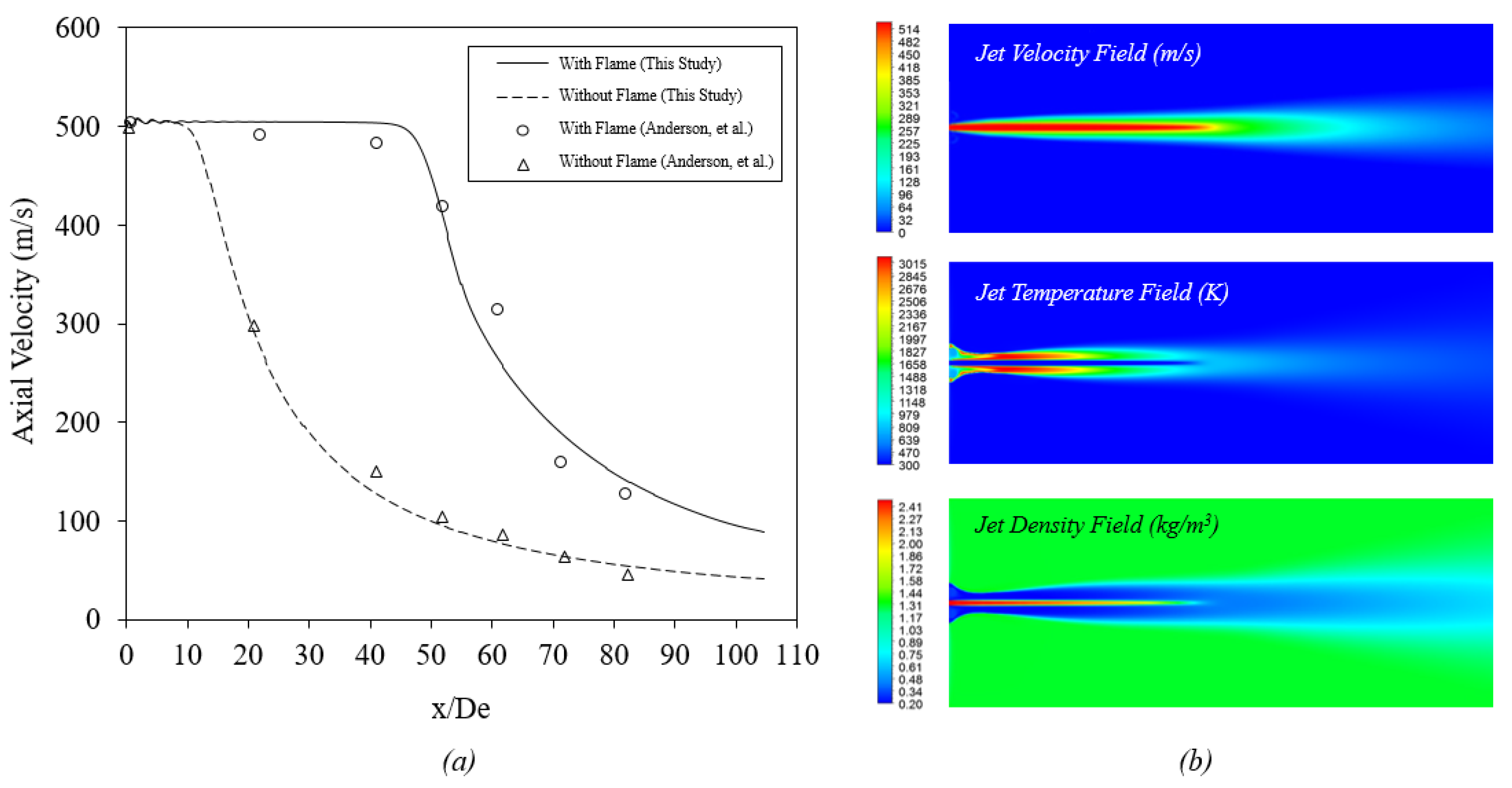
  • The supersonic coherent jet with the revised k ε turbulence model will be firstly simulated in an open space under the actual high ambient temperature conditions inside the furnace to obtain the jet characteristics, which will be used for the subsequent estimation and simulation.
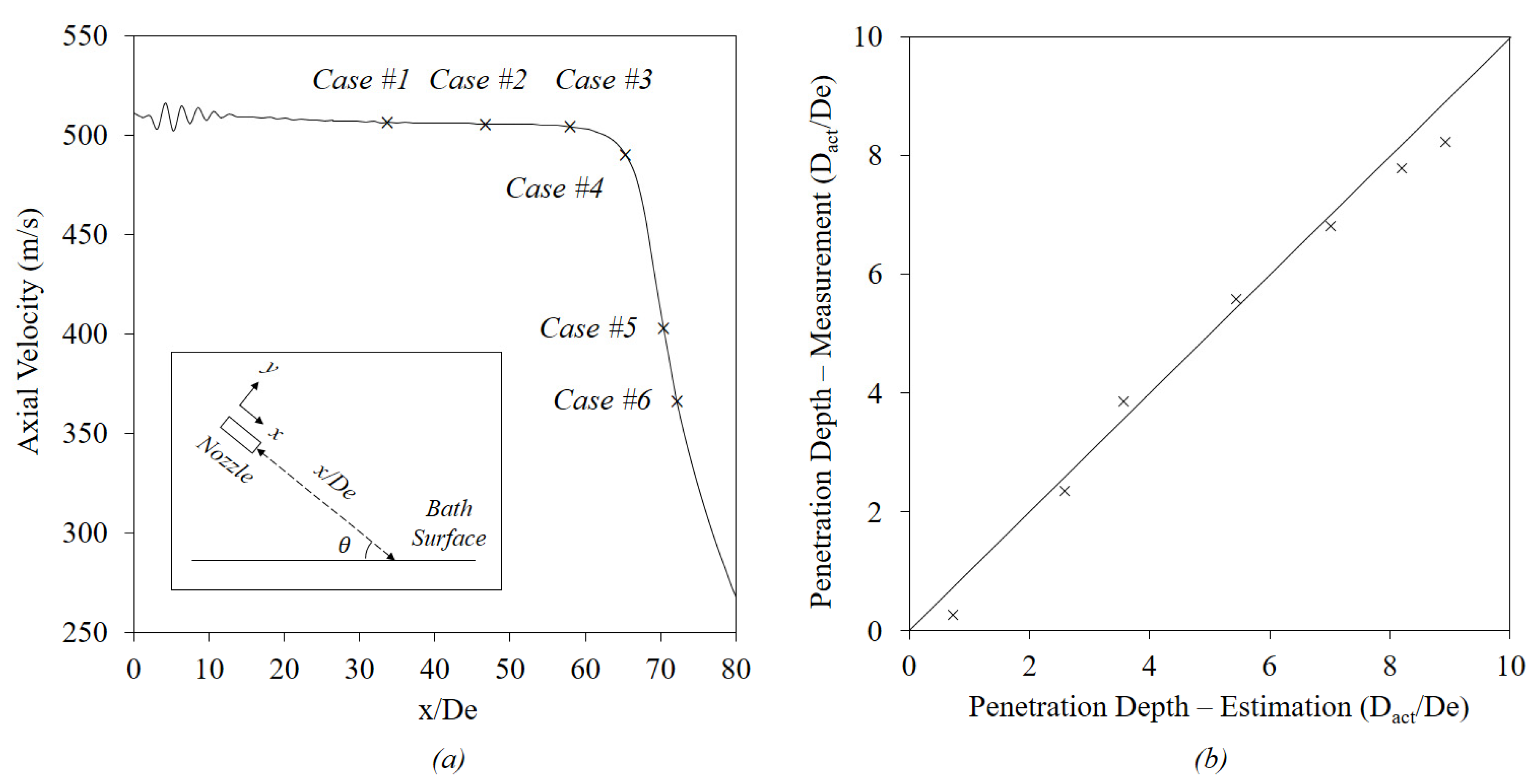
  • A theoretical interface will then be calculated to represent the jet penetration cavity inside the liquid steel bath based on the supersonic coherent jet characteristics at the bath surface. This method is based on the energy balance between the injected jet and penetrated bath and enables us to avoid the direct simulation of the supersonic coherent jet interacting with the liquid steel bath.
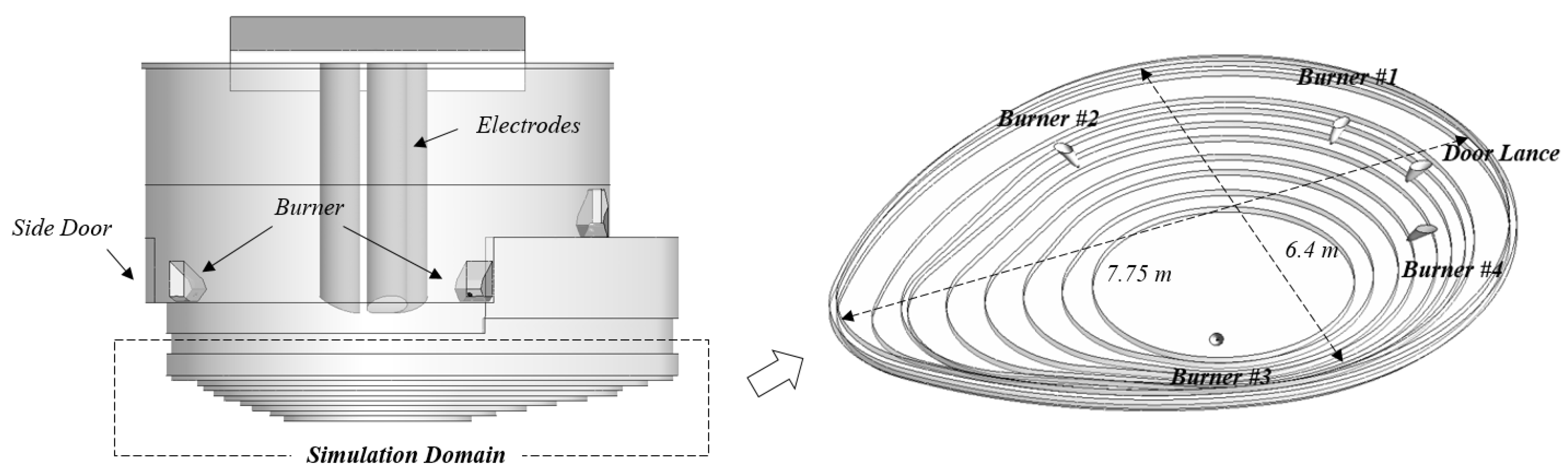
  • The geometry of the bottom section of the EAF with the above-estimated jet cavity can be established and reasonable boundary conditions need to be defined on the cavity surface according to the results from part 1, so that the thermodynamic and kinetic coupled multiphase reacting flow simulation can be performed to predict in-bath stirring and decarburization process for the refining stage.
The CFD simulation of part 1 and part 3 mentioned above is based on solving the appropriate Navier-Stokes equations with the required source terms of the specific phenomenon and incorporating them into the finite volume method (FVM) of Patankar [12]. A commercial software ANSYS® FLUENT 19.1 (ANSYS Inc., Washington County, PA, USA, 2019) [13] was adopted for the simulation.
This 3D integrated model can eliminate the compatibility issue of different CFD models during multi-physics simulations, especially for the consideration of the interaction between multi phases. Besides, the adoption of the current model makes the three-dimensional modeling of the decarburization process possible, which provides the way for a more comprehensive analysis of the chemical reaction rate and the species distribution inside the liquid steel bath. The complete model will be detailed in the next section.

3. Numerical Model

3.1. Supersonic Coherent Jet Modeling

The supersonic coherent jet is modeled with the assumption that the jet flow is conducted in a steady, compressible, non-isothermal process. The corresponding Navier-Stokes equations were solved with the modification of the k ε turbulence model, which aims to improve the prediction accuracy of the jet potential core length and oxygen delivery rate and provide correct numerical conditions to estimate the subsequent jet penetration cavity shape and simulate the decarburization process. The governing equations solved are listed below.
The continuity conservation equation can be expressed by:
· ( ρ v ) = 0 ,
The momentum conservation equation is represented as:
· ( ρ v v ) = p + · ( τ = ) + ρ g + F ,
where ρ is the fluid density; v is the velocity vector; p is the static pressure; τ = is the stress tensor; g is the acceleration of gravity and F is the external body force.
The energy conservation equation can be written as:
· [ v ( ρ E + p ) ] = · [ ( k + c p μ t P r t ) T j h j J j + ( τ = e f f · v ) ] + S h ,
where E is the total energy related to the sensible enthalpy h ; k is the thermal conductivity; c p is the specific heat; μ t is the turbulent viscosity; P r t is the turbulent Prandtl number whose default value is 0.85 for the k ε turbulence model. For the free shear flow with high heat transfer simulation, the appropriate turbulent Prandtl number should be set as 0.5 according to the suggestions by Wilcox [14] and Alam [3]. However, the shrouding combustion flame around the primary supersonic oxygen jet prevents the entrainment of ambient gas into the center jet, which further impacts the generation of the free shear layer. Thus, 0.85 was still adopted for the turbulent Prandtl number to estimate the turbulent thermal conductivity in the current model. J j is the diffusion flux of substance j and S h is the volumetric heat sources including the heat of chemical reaction during the simulation.
Considering the supersonic state of the primary oxygen jet, the flow turbulence can be resolved through a time-averaged velocity scalar. In the present study, the averaged Reynolds stresses term was determined using the modified k ε turbulence model originally proposed by Launder and Spalding [15]. The governing equations of the turbulent kinetic energy k and turbulence dissipation rate ε can be expressed by:
x i ( ρ u i k ) = ρ u i u j ¯ u j x i + x i ( μ + μ t σ k k x i ) ρ ε ρ ε M τ 2 ,
x i ( ρ u i ε ) = C ε 1 ρ u i u j ¯ ε k u j x i + x j ( μ + μ t σ ε k x j ) C ε 2 ρ k 2 ε ,
where μ is the molecular viscosity; σ k and σ ε are the turbulent Prandtl number for k and ε , whose values are 1.0 and 1.3, respectively; M τ is the turbulent Mach number that can be defined as:
M τ = 2 k a ,
where a is the acoustic velocity; C ε 1 and C ε 2 are constants whose values are 1.44 and 1.92, respectively.
The turbulent viscosity μ t used in Equations (4) and (5) is defined by:
μ t = C μ ρ k 2 ε ,
where C μ is a constant value originally equal to 0.09 for the standard k ε turbulence model. In order to consider the influence of the entrained ambient gas that is reduced by the shrouding combustion flame, C μ was modified according to the formula proposed by Alam et al. [3]. The original value of C μ was divided by a variable C T to include the effects of the local total temperature gradient in estimating the turbulent viscosity, thereby further reducing the mixed growth rate of the shear layer to accurately simulate the jet potential core length [16]. The modified C T can be expressed as:
C μ = 0.09 C T
and
C T = 1 + C 1 T g m 1 + C 2 f ( M τ ) ,
where C 1 , C 2 and m is constantly equal to 1.2, 1.0 and 0.6, respectively; T g is the normalized local total temperature gradient, which can be calculated by:
T g = k 3 2   | T t | ε   T t ,
where T t is the local total temperature of the flow field; f ( M τ ) is a function that further considers the influence of turbulent Mach number, which can be estimated by:
f ( M τ ) = ( M τ 2 M τ 0 2 )   H ( M τ M τ 0 ) ,
where H ( x ) is the Heaviside function; M τ 0 is a constant equal to 0.1 [17]. All aforementioned modifications of the standard k ε turbulence model are incorporated into the CFD-solver Fluent through the user-defined function (UDF) code based on C language and compiled in the CFD solver for the simulation.
In order to capture the shrouding combustion flame, the species transport model with the eddy dissipation concept (EDC) [18] was employed to simulate the 28-step natural gas-oxygen combustion reactions. The Discrete Ordinates (DO) radiation model with Weighted-Sum-of-Gray-Gases Model (WSGGM) [19] was adopted to model the radiation heat transfer phenomenon for the combustion.
The numerical simulation domain of the supersonic coherent jet is shown in Figure 2, which contains 3 million computational cells totally. Total computational time is around 15 h if using 80 cores in the High Performance Computing (HPC) cluster to obtain the converged results. The simulation domain is a cylindrical-shaped vessel originating from the exit of the converging-diverging nozzle where the nozzle structure is ignored. The dimension of the vessel is much larger than the burner, which can be used to simulate the supersonic coherent jet behavior in the open space. Therefore, except for the wall where the nozzle exit is located, the other walls of the vessel are set as outlets. More detail on burner operating conditions and other information are mentioned in another published paper [20].

3.2. Jet Penetration Cavity Estimation

The present study utilized a novel method to consider the jet penetration in the liquid steel bath so that the direct simulations of interaction between multi phases can be avoided. The basic idea is to calculate a theoretical interface to represent the jet penetration cavity inside the liquid steel bath and this cavity will be estimated based on the characteristics of the coherent jet reaching the bath surface and used as the physical boundary of the computational domain for subsequent decarburization simulations. The shape of the cavity interface is assumed to be a revolution paraboloid according to Memoli et al. [11], which is more precise for the coherent jet with high momentum, as its penetration depth is greater than the radius of its cross-section. The three-dimensional mathematical expression of a revolution paraboloid in Cartesian coordinate can be written as:
z = x 2 + y 2 c ,
where c is the constant need to be defined by a given volume of the jet penetration cavity and the penetration depth.
The volume of the jet penetration cavity V can be determined by calculating liquid steel replaced by the gas flow based on the impulsive balance at the cavity interface if ignoring the impact of the liquid steel surface tension [21]. The expression of the jet cavity volume can be written as:
V = π ρ j v j 2 d j 2 4 g ρ s ,
where ρ j and ρ s are the density of primary oxygen jet and liquid steel, respectively; v j and d j are the primary oxygen jet velocity and diameter when at bath surface, which can be determined through the supersonic coherent jet modeling of a given distance from the nozzle exit to the bath.
Jet penetration depth D refers to an empirical formula derived by Ishikawa et al. [22], which describes the penetration depth created by the turbulent jet. For the supersonic coherent jet, the constants in the formula need to be modified accordingly. The empirical formula shows the relationship between the jet penetration depth of a single-hole or multi-holes nozzle and the burner operating conditions, which can be expressed as:
D = γ h 0 e σ 1 L γ h 0 c o s   θ
γ h 0 = σ 2 ( V ˙ 3 n d ) ,
where L is the axial distance between the nozzle exit to the bath surface; θ is the angle of the jet inclination; V ˙ is the volume flow rate of primary oxygen jet; n is the number of the nozzle and equal to 1 for the current study; d is the nozzle exit diameter for primary oxygen jet; σ 1 and σ 2 are two constants originally equal to 1.77 and 1.67, respectively and those two parameters are determined through experiments for a specific type of coherent jet used in the present study.
The actual refining process has the slag layer covering the liquid steel bath to protect the arc and reduce heat radiation loss. The coherent jet needs to pass through the slag layer before reaching the liquid steel bath. During this period, the jet will lose some of its momentum. Therefore, the jet penetration depth should be shorter than the one without the slag layer. In the current model, the slag layer is assumed to be converted equivalently to a corresponding liquid steel layer to include its effect on the jet penetration depth. The equivalent slag layer height h s can be estimated by:
h s = ρ s l ρ s h s l ,
where ρ s l and h s l are the values for slag layer density and slag layer height, respectively. The actual jet penetration depth D a c t reads as:
D a c t = D h s .
Once the constant c is determined by solving Equations (13) to (17), the theoretical parabolic jet cavity interface can be defined and included as the physical boundary for the computational domain of the bottom section of the EAF for the decarburization simulation. This eliminates the need to include the consideration of supersonic jets and its interaction with the liquid surface in the decarburization simulation. The estimation of the three-dimensional jet penetration cavity based on actual burner operating conditions is illustrated in Figure 3 and the computational domain with five jet penetration cavities established according to the actual burner arrangement provided by industry is given in Figure 4. This computational domain is going to be used in subsequent decarburization simulations.
Notice that when the supersonic coherent jet impinges on the liquid steel bath forming the jet penetration cavity, the exchange of energy and substance occurs intensively between the gas phase and liquid phase. Therefore, the jet penetration cavity surface, as the physical boundary of the computational domain, needs to establish appropriate boundary conditions to consider the energy and substance transfer during the jet impingement. In the present study, both jet momentum transfer and delivery of the oxygen were considered. Based on the energy balance on the cavity surface, the jet momentum transferred to the liquid steel bath P s , a v g can be expressed as:
P s , a v g = α ρ O 2 v O 2 2 A = α ρ O 2 2 A ρ s [ 1 Δ z z 2 z 1 v O 2 ( z ) d z ] 2 ,
where α is the transferable percentage of the jet total momentum at liquid steel bath, which is 0.06 according to the reference [23]; v O 2 is average jet velocity along cavity centerline; A is the cavity surface area; Δ z is the length of the cavity centerline, which is equal to z 1 z 2 .
The amount of oxygen delivered to the liquid steel m O 2 ,   a v g through the jet cavity can be estimated by calculating the average oxygen distribution along the cavity centerline:
m O 2 ,   a v g = 1 Δ z z 2 z 1 m O 2 ( z ) d z .

3.3. Decarburization Modeling

The current decarburization modeling focuses on the refining process after the solid scrap is completely melted down into a flat bath. Therefore, the scrap melting phenomenon is not included in the present study for the sake of simplicity. The model proposed here considers a liquid steel-oxygen two-phase reacting flow system inside the flat bath and the simulation domain, as mentioned above, only includes the bottom section of EAF with estimated jet penetration cavities, through which the oxygen enters the domain to react with carbon and other impurities. The injected oxygen also results in two main effects on the system including the stirring of the liquid steel bath and the bath temperature rise due to the heat released by the oxidation reactions. In the present study, the oxidations of the carbon, iron and manganese as a mixture of liquid steel by the injected oxygen are listed in Table 1:
Oxidation reactions take place in cells of the simulation domain that contain the oxygen. The oxidation rates of carbon, iron and manganese at high carbon content are mainly limited by the amount of oxygen contained in the same cell. If the oxygen is sufficient, the rate equations can be written as suggested by Wei and Zhu [24]:
W s 100   M C d [ % C ] d t = 2 η C Q O 2 22 , 400 x C
W s 100   M M n d [ % M n ] d t = 2 η M n Q O 2 22 , 400 x M n ,
where W s and Q O 2 is the mass of liquid steel and the volume of oxygen in the corresponding cell, respectively; M i is the mole mass of each substance; η i is the efficiency factor of each substance, which is a function of total mixing of the system and can be estimated based on the work done by Shukla et al. [25]; x i is the oxygen distribution ratios of each substance and is assumed to be proportional to the Gibbs free energies of corresponding oxidation reactions:
x C = Δ G C Δ G C + Δ G F e + Δ G M n
x M n = Δ G M n Δ G C + Δ G F e + Δ G M n ,
where the Gibbs free energies Δ G i of respective substance can be defined as:
Δ G C = Δ G C 0 + R T l n [ P C O a C · a O 2 0.5 ]
Δ G F e = Δ G F e 0 + R T l n [ a F e O a F e · a O 2 0.5 ]
Δ G M n = Δ G M n 0 + R T l n [ a M n O a M n · a O 2 0.5 ] ,
where Δ G i 0 and a i is the standard Gibbs free energy and the activity of each substance in the bath respectively; R is gas constant; P C O is the partial pressure of carbon monoxide.
At low carbon content, the oxidation rate of carbon is no longer controlled by the oxygen contained in the cell. Instead, the mass carbon transfer rate to liquid steel will directly impact the decarburization rate, which can be expressed as:
W s d [ % C ] d t = ρ s k C A i n t e r   ( [ % C ] [ % C ] e ) ,
where A i n t e r is the bubble inter-surface area; [ % C ] e is carbon equilibrium concentration in the molten bath; k C is the carbon mass transfer coefficient through the oxygen bubble surface which can be calculated by [26]:
k c = 0.59 · [ D C · ( u r e l / d B ) ] 0.5 ,
where D C is the diffusion coefficient of carbon; u r e l is relative velocity of liquid steel; d B is the bubble diameter.
The oxides formed through Reaction (A) to Reaction (C) may gradually float upwards to the top surface, which is the lower surface of the slag layer that is not included in the simulation domain. Practically, the oxides will accumulate at the slag layer and have further reactions there. The absorption of the oxides by slag layer can be achieved computationally by removing the corresponding oxides that are in contact with the domain top surface. The process described above is illustrated in Figure 5.
During the refining stage, the temperature of the liquid steel bath increases due to the energy released by the oxidation reactions. The amount of energy released to the bath can be estimated by the oxidation rates and the oxidation enthalpies Δ H i of each reaction, where Δ H i is a function of bath temperature and taken from reference [27]. Thus the rate of energy-generating in a cell due to the oxidations can be expressed as:
d E r e a c d t = Δ H i W s d [ % i ] d t ,
where i represents the carbon, iron and manganese considered in the liquid steel bath.
The current liquid steel-oxygen two-phase reacting flow system was solved in the numerical simulation domain given in Figure 4, which has 2.5 million computational cells totally. By adopting the Eulerian model with the appropriate source terms compiled through user-defined function (UDF) code, the model is able to achieve the above-described simulation of in-bath oxidation reactions and heat release. The total computational time needed to simulate 1000 s decarburization process is around 50 h if using 0.05 s time step size and 80 cores in the HPC cluster.

4. Simulation Results and Discussions

4.1. Model Validaiton

The validation of the coherent jet modeling in ambient air with and without shrouding flame was conducted based on the research works done by Anderson et al. [2]. The simulation was set up according to the reported experiment. The comparison of the jet axial velocity distribution between the present study and the measurement data is given in Figure 6a. The jet with the shrouding flame can maintain its initial velocity for a longer distance compared with the jet without the shrouding flame. The coherent jet with Mach 2.1 at nozzle exit has the potential core length around 48 De (where De is the diameter of the converging-diverging nozzle exit), which is 2.5 times longer compared with the conventional jet in this validation. On the contours given in Figure 6b, the entrainment of the ambient air is blocked by the shrouding combustion flame, which significantly reduces the turbulence effect around the primary oxygen jet leading to the great increase of the potential core length. The average difference in this validation is 5.9% compared with experimental data, which shows good accuracy of current supersonic coherent jet modeling.
The validation of the jet penetration cavity estimation was done by comparing the predicted jet penetration depth with the measurement data provided by Praxair under the same burner operating conditions. It should be noted that the burner configuration of the coherent jet used for current validation differs from the above-mentioned coherent jet validation. The key parameters of bath for jet penetration cavity estimation are given in Table 2. The jet penetration depth is measured under the fixed burner operating conditions. The distance between the jet nozzle exit and the liquid steel bath surface is successively increased to reach different penetration depths, thereby obtaining six sets of available data for the validation as shown in Figure 7a. The parity plot of the jet penetration depth inside the liquid steel bath is given in Figure 7b showing the comparison of the estimation in the present study and the experimental data by Anderson, et al. The jet penetration reduces exponentially as the nozzle moves away from the liquid surface. This is because when the nozzle-liquid surface distance is greater than the jet potential core length, no doubt increasing the distance (cases #4 to #6 in Figure 7a) will decrease the jet penetration depth since smaller momentum the jet will have when reaching the liquid bath surface. On the other hand, if the nozzle-liquid surface distance is less than the jet potential core length, the jet maintains the same axial velocity but the area of the jet mixing zone in the radial direction increases with the increase of the nozzle-liquid surface distance (cases #1 to #3 in Figure 7a). This results in a reduction of the jet maximum pressure gradient in the mixing zone, thereby reducing the jet penetration ability inside the liquid steel bath. The tendency of the estimation in the present study meets the above description and the error compared with measurement data is less than 5% showing a good accuracy of the estimation.
The current 3D integrated model was adjusted accordingly to predict the decarburization process of the industrial electric arc furnace for model validation. Under the same furnace operating conditions, the percentage error of the decarburization rate prediction given by the model is less than 7% compared with industrial data.

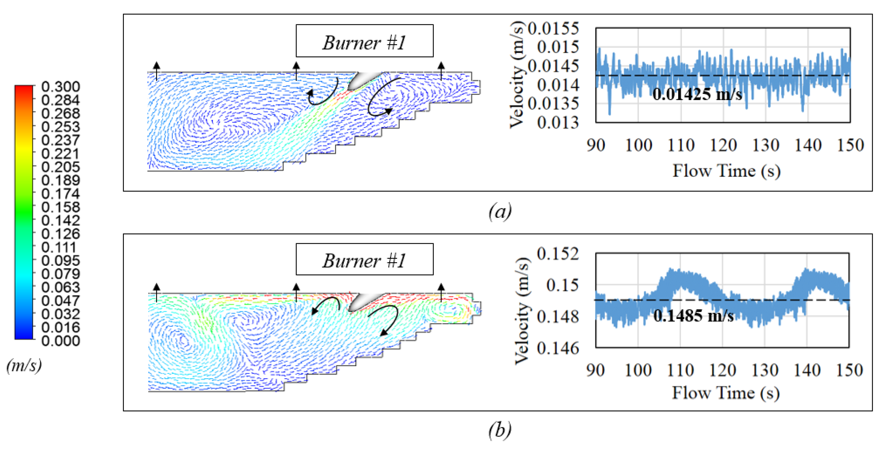
4.2. Stirring Mechanism

Generally, there are different stirring mechanisms that affect the flow characteristics of the molten bath, including the momentum stirring, the bubble stirring and the electromagnetic stirring. In addition, the buoyancy force arising from the bath temperature gradient and the bath concentration gradient will also make contributions to stir the bath. In the present study, the electromagnetic stirring is assumed to be neglected in this alternating current (AC) EAF since the electromagnetic field induced is limited to the small region around the arcs and has a minor effect on the molten bath flow [28,29,30]. The stirring caused by the buoyancy-driven flow is always included in the model by applying the Boussinesq hypothesis for the liquid steel phase since it is a natural phenomenon built in any thermal system. As for the rest two stirring mechanisms, that is, the momentum stirring and the bubble stirring, they are the main stirring power provided by the supersonic coherent jet to the refining process, which are valuable and feasible to be investigated using the 3D integrated model proposed above.
In the actual steel refining process, the distance between the burner nozzle exit and the liquid steel bath surface is usually controlled to be within the jet potential core length to guarantee the coherent jet can maintain a relatively high kinetic energy when reaching the liquid steel bath. In this case, the coherent jet is able to push the liquid steel aside to form a cavity and transfer the momentum to the bath simultaneously. Generally, only a portion of the jet momentum can be transferred to a liquid steel bath and further used to generate the stirring. Sano et al. [23] reported that only 6% of the total jet momentum is transferable to the liquid steel and this value has also been proved to be suitable for the current simulation under the given burner operating condition. The stirring generated by this direct momentum transfer is called the momentum stirring. Another critical stirring mechanism during the refining process is the bubble stirring. The decarburization reaction will generate the CO bubbles that float upward together with oxygen bubbles quickly, creating a strong stirring power inside the liquid steel bath due to the bubble-liquid drag force. The CO bubbles will eventually be absorbed by the slag layer and subsequent chemical reactions will occur there. It has been reported that bubble stirring plays a key role in the homogenization of the flow field, therefore the corresponding investigation conducted below is aimed to reveal the impact of those two stirring mechanisms on the development of the flow field.
The comparison of the flow filed with and without the bubble stirring is given in Figure 8. Figure 8a shows the case only considering the momentum stirring. It can be seen that the high momentum transferred from the surface of the jet penetration cavity pushes the liquid steel downward, resulting in a high-speed liquid steel flow in the axial direction of the cavity together with vortexes generated on both sides. The volume-averaged liquid steel velocity in the bath fluctuates most frequently around a value of 0.01425 m/s. Figure 8b shows the case considering both the momentum stirring and the bubble stirring. Because of the bubble stirring, the high-velocity region occurs surrounding the jet penetration cavity instead and the direction of the vortex changes significantly. This is mainly due to the intensive oxidation reactions in that region generating a large number of oxides and the stirring intensity of the momentum transfer became much weaker compared to that of the floating CO and oxygen bubbles. In addition, significant turbulence is generated through bubble stirring in the liquid steel bath as well, which can lead to a better mixing. The volume-averaged velocity of the liquid steel bath is approximately 0.1485 m/s, which is about 10 times as much as the case only considering the momentum stirring. From this comparison, it can be seen that bubble stirring greatly promotes the homogenization of the liquid steel bath and is one of the most important stirring mechanism in the EAF refining stage.
The bath mixing efficiency evaluation for both cases was conducted as well and the results are given in Figure 9. A tracer is introduced in the center of the liquid steel bath and the simulations stop once the tracer is fully diffused inside the bath. During the simulation, the area-averaged concentration of the tracer is monitored at three different horizontal planes in the bath to evaluate the mixing time. The vertical distance between those three horizontal planes and the bottom of the furnace is 0.07 m (plane monitor 1), 0.47 m (plane monitor 2) and 0.57 m (plane monitor 3), respectively. Noticed that, plane monitor 1 is close to the furnace bottom surface, which is aimed to avoid the dead zone and guarantee the full diffusion of the tracer in the domain. Figure 9a shows the contours of the in-bath tracer mass fraction variation over time. Figure 9b,c show the molar concentration variation of the tracer over time. When the variation in the molar concentration of the tracer is negligible, the mixing time required for the liquid steel bath to reach full diffusion can be obtained. It can be seen that without the bubble stirring, the mixing time is estimated to be 1665.3 s, which is almost 9.5 times longer than the time needed for the case with the bubble stirring. Therefore, the bubble stirring needs to be considered in the stirring mechanism for the future simulation of the liquid steel flow field.

4.3. Decarburization Rate and Bath Temperature Rising Rate

The thermodynamic and kinetic coupled two-phase reacting flow simulation can be performed by the proposed 3D integrated model to reveal the details of species concentrations and temperature distribution inside the liquid steel bath and to predict the overall decarburization rate and bath temperature rising rate in the refining stage.
Generally, the average carbon content and the bath temperature are two important indicators for the operators to decide whether liquid steel meets the requirement of tapping. The volume-averaged carbon mass fraction and bath temperature predicted by this 3D integrated model are plotted in Figure 10 and Figure 11. From the simulation results, after 800 s (around 13 min), the bath temperature will be increased to 1918 K with carbon content reduced to 0.056%. The percentage of carbon reduction and bath temperature increasing is 86.3% and 5.7% respectively. It is reported that the time required to reach the same carbon content and bath temperature during the actual refining process is about 12 to 15 min and current results give a correct prediction by comparing with the data published in the reference [31].
The contours given in Figure 10 and Figure 11 also show the detailed distribution for both in-bath carbon content and temperature field, which are plotted on the cross-section plane through burner #1 at 200 s, 400 s, 600 s and 800 s. The initial temperature and carbon content are assumed to be 1815 K and 0.41% by mass respectively. It can be seen that the carbon content maintains relatively low around the jet penetration cavity region due to a large amount of the oxygen bubbles injected from the cavity surface. The oxygen will first oxidize the reactive substances in this area and the excess oxygen will either travel with the flow to other areas away from the cavity or float upward by the buoyancy and be absorbed at the slag layer bottom surface (domain top surface). Generally, due to the concentration difference and stirring effect, the carbon will continue to move to the vicinity of the jet penetration cavity and react with the remaining or newly injected oxygen to generate the CO bubbles. The CO bubbles can float up with the flow causing the aforementioned in-bath bubble stirring and be absorbed once reaching the domain top surface. Moreover, since the oxygen reactions mainly occur around the cavity, a large amount of chemical energy will be released there to heat up the liquid steel. Therefore, a red region representing high temperature can be seen around the jet penetration cavity in the contours. This thermal effect will spread to the entire liquid steel bath over time, resulting in significant bath temperature rise.

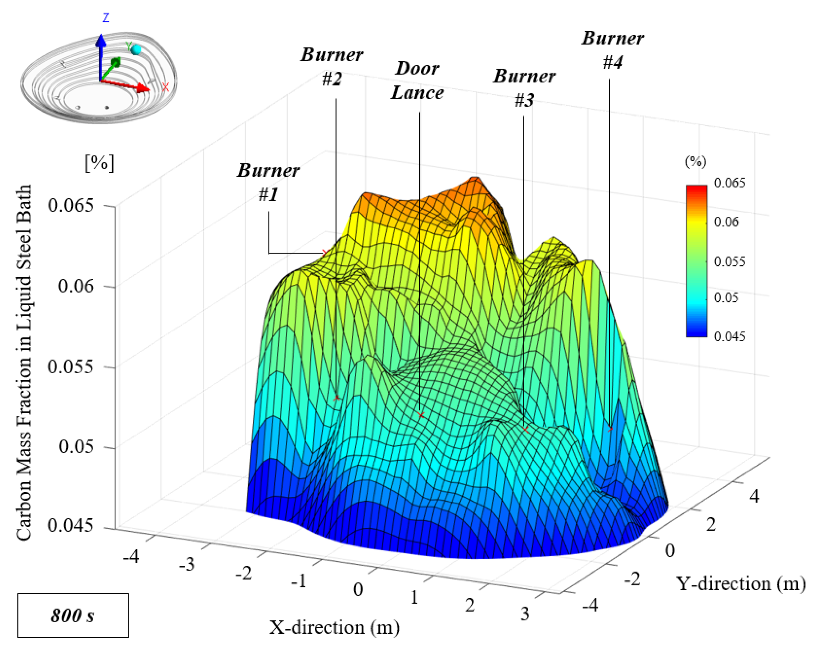
4.4. Carbon Distribution in Liquid Steel Bath

The current burner arrangement of the furnace is based on the arrangement commonly used in the industry, that is, the four burners are pointed 45-degree downward. The current simulation also takes the decarburization effect of door lance into account, which is used to make an immerged oxygen injection. Thus a total of five jet penetration cavities was established in the simulation domain.
Compared with other models, the current proposed 3D integrated model can analyze the detailed variation of the carbon distribution inside the liquid steel bath using the CFD technique. The simulation results are plotted in Figure 12. It can be seen that the current burner arrangement will result in an uneven carbon distribution in the liquid steel bath and the decarburization rate in front part of the furnace is much slower than elsewhere. When the refining progresses reaches around 200 s (about 3 min), the average carbon content in front part of the furnace is about twice higher than that of other places. It is not difficult to tell from the arrangement of the burners that most of the burners are located in the middle or rear of the furnace, which leads to the issues including the weak stirring and less oxygen injection in front of the furnace. The decarburization in this front area mainly depends on the overall flow pattern in the bath, that is, the liquid steel carrying high carbon content flows from the front of the furnace to the middle and rear of the furnace under specific rotating pattern so that the carbon content can be reacted with rich oxygen injected from the burner in that area. Obviously, this way of decarburization highly depends on the overall bath flow pattern and has a relatively low decarburization rate in the front of the furnace, which may result in a potential issue.
Figure 13 plots the detailed carbon mass fraction distribution on a plane (0.5 m from furnace bottom) close to the end of the refining process. The fraction of in-bath carbon content required for the liquid steel tapping is usually to be 0.03% to 0.05% by mass. It can be seen from the figure that the aforementioned uneven distribution of carbon content still exists at the end of the refining. In the actual operation of EAF refining stage, the operator typically inserts the test rod into the liquid steel bath through the side door to measure the carbon content, whose value is used to represent the average carbon content of the entire bath being tested. Once the temperature and carbon content meets the requirement, the liquid steel will be tapped. However, the measurement at this time only reflects the actual carbon content at the rear of the furnace. According to the previous analysis, the front of the furnace was not well stirred in the entire refining process. Thus, the actual carbon content was much higher there compared with the carbon content at the rear of the furnace. If the measured value is used to represent the average in-bath carbon content under this situation, it can potentially under predict the actual carbon content and further affect the quality of tapped liquid steel. By using this 3D integrated model, multiple cases can be simulated with acceptable computational time to optimize the burner arrangement to achieve higher stirring and decarburization rate.

5. Conclusions

A complete 3D integrated model including the coherent jet modeling, the jet penetration cavity estimation and the decarburization modeling was proposed in this study and the validations for three parts were conducted respectively. The 3D integrated model can avoid the direct simulation of the supersonic coherent jet interacting with the liquid steel bath and provide a possible method to simulate the liquid steel-oxygen two-phase reacting flow system for the decarburization prediction with acceptable computational time. The conclusions made by adopting this 3D integrated model in EAF refining simulation are listed below:
  • The stirring mechanism was analyzed using the model and the results indicated that the bubble stirring greatly promotes the homogenization of the liquid steel bath and is one of the most important stirring mechanism need to be considered in the EAF refining simulation.
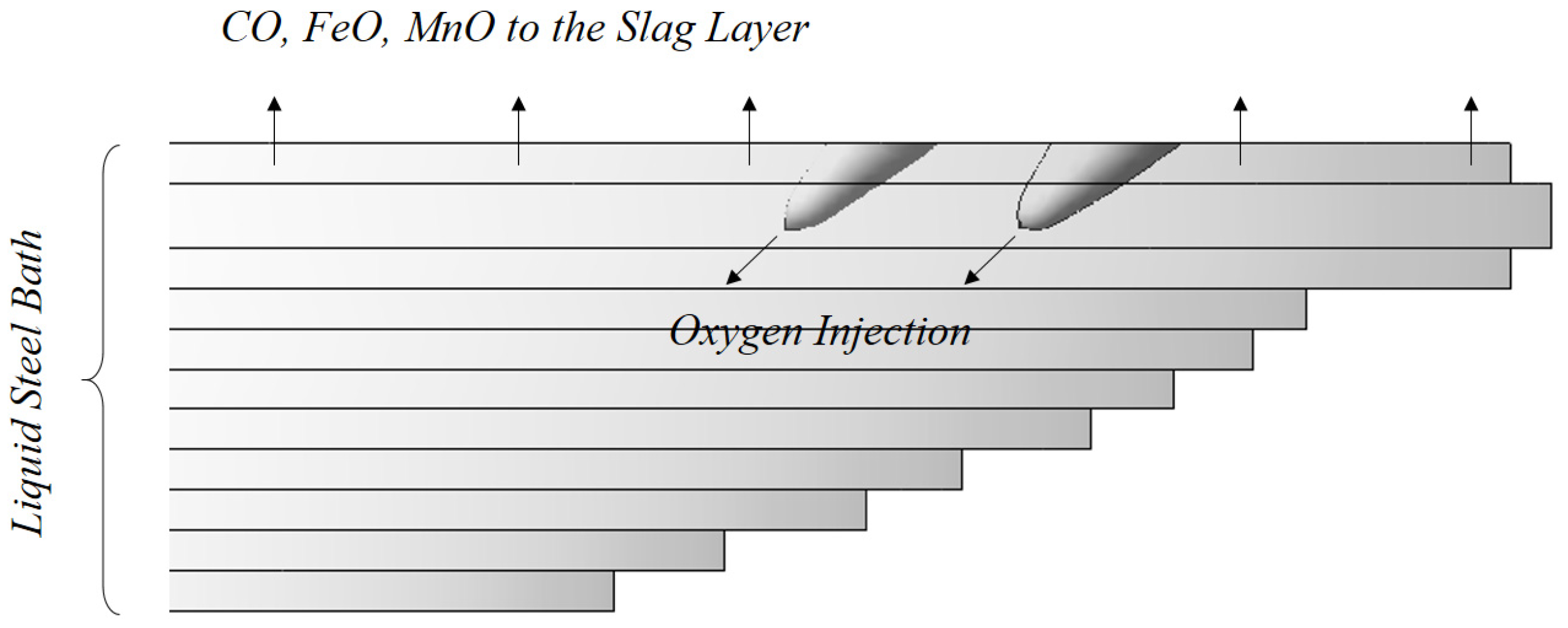
  • The decarburization rate and bath temperature distribution were investigated as well. The 3D integrated model indicated that decarburization mainly occurs around the jet penetrating cavity and due to the oxidation reaction, a large amount of chemical energy will be released there to increase the bath temperature. The overall bath decarburization rate and temperature rising rate predicted by the model has good agreement with reference data.
  • 3D carbon distribution in the liquid steel bath was also investigated by the model. The results illustrated that the burner arrangement considered in present study results in an uneven bath decarburization rate, which is mainly due to the less oxygen-blowing and weak bath-stirring in front of the furnace. The uneven carbon concentration may lead to the under-prediction of the actual carbon content inside the furnace and further affect the quality of tapped liquid steel.

Author Contributions

Conceptualization, Y.C.; methodology, Y.C.; software, Y.C.; validation, Y.C.; formal analysis, Y.C.; investigation, Y.C.; resources, Y.C.; data curation, Y.C.; writing—original draft preparation, Y.C.; writing—review and editing, Y.C. and A.K.S.; supervision, C.Q.Z.; project administration, C.Q.Z.; funding acquisition, C.Q.Z. All authors have read and agreed to the published version of the manuscript.

Funding

This research was funded by Steel Manufacturing Simulation and Visualization Consortium (SMSVC).

Acknowledgments

The authors would like to thank the Steel Manufacturing Simulation and Visualization Consortium (SMSVC) members for funding this project. The Center for Innovation through Visualization and Simulation (CIVS) at Purdue University Northwest is also gratefully acknowledged for providing all the resources required for this work. The authors also appreciate the great help from Yury Krotov (Steel Dynamics, Inc.), Joseph Maiolo (Praxair) and Hamzah Alshawarghi (Praxair).

Conflicts of Interest

The authors declare no conflict of interest. The funders had no role in the design of the study; in the collection, analyses or interpretation of data; in the writing of the manuscript or in the decision to publish the results.

References

  1. Mathur, P.; Messina, C. Praxair CoJet™ Technology–Principles and Actual Results from Recent Installations. AISE Steel Technol. 2001, 78, 21–25. [Google Scholar]
  2. Anderson, J.E.; Farrenkopf, D.R. Coherent gas jet. U.S. Patent 5,823,762, 20 October 1998. [Google Scholar]
  3. Alam, M.; Naser, J.; Brooks, G.; Fontana, A. Computational fluid dynamics modeling of supersonic coherent jets for electric arc furnace steelmaking process. Metall. Mater. Trans. B 2010, 41, 1354–1367. [Google Scholar]
  4. Liu, F.; Zhu, R.; Dong, K.; Hu, S. Flow field characteristics of coherent jet with preheating oxygen under various ambient temperatures. ISIJ Int. 2016, 56, 1519–1528. [Google Scholar] [CrossRef] [Green Version]
  5. Li, Z.L.; Zhang, L.L.; Cang, D.Q. Temperature corrected turbulence model for supersonic oxygen jet at high ambient temperature. ISIJ Int. 2017, 57, 602–608. [Google Scholar] [CrossRef] [Green Version]
  6. Caffery, G.; Warnica, D.; Molloy, N.; Lee, M. Temperature homogenisation in an electric arc furnace steelmaking bath. In Proceedings of the International Conference on CFD in Mineral and Metal Processing and Power Generation; CSIRO: Canberra, Australia, 1997; pp. 87–99. [Google Scholar]
  7. Li, B. Fluid flow and mixing process in a bottom stirring electrical arc furnace with multi-plug. ISIJ Int. 2000, 40, 863–869. [Google Scholar] [CrossRef] [Green Version]
  8. Ramírez, M.; Alexis, J.; Trapaga, G.; Jönsson, P.; Mckelliget, J. Modeling of a DC electric arc furnace—Mixing in the bath. ISIJ Int. 2001, 41, 1146–1155. [Google Scholar] [CrossRef] [Green Version]
  9. Szekely, J.; Asai, S. Decarburization of stainless steel: Part II. A mathematical model and a process optimization for industrial scale systems. Metall. Trans. 1974, 5, 1573–1580. [Google Scholar] [CrossRef]
  10. Zhu, F.Y.; Chi, H.B.; Jiang, X.Y.; Mao, W.D. Process and Practice of EAF with De-P Hot Metal Charging for Melting Stainless Steel. In Materials Science Forum; Trans Tech Publications Ltd.: Zurich, Switzerland, 2007; Volume 561, pp. 1063–1066. [Google Scholar]
  11. Memoli, F.; Mapelli, C.; Ravanelli, P.; Corbella, M. Simulation of oxygen penetration and decarburisation in EAF using supersonic injection system. ISIJ Int. 2004, 44, 1342–1349. [Google Scholar] [CrossRef] [Green Version]
  12. Patankar, S. Numerical Heat Transfer and Fluid Flow; Taylor & Francis: Abingdon, UK, 2018. [Google Scholar]
  13. ANSYS FLUENT Release 19.1; ANSYS Inc., ANSYS Academic Research: Canonsburg, PA, USA, 2013.
  14. Wilcox, D.C. Turbulence Modeling for CFD; DCW Industries: La Canada, CA, USA, 1998; Volume 2.
  15. Wolfshtein, M.; Lin, A.; Naot, D. Mathematical Models of Turbulence; No. BOOK; Academic Press: Cambridge, MA, USA, 1972. [Google Scholar]
  16. Alam, M.; Naser, J.; Brooks, G. Computational fluid dynamics simulation of supersonic oxygen jet behavior at steelmaking temperature. Metall. Mater. Trans. B 2010, 41, 636–645. [Google Scholar] [CrossRef]
  17. Abdol-Hamid, K.S.; Pao, S.P.; Massey, S.J.; Elmiligui, A. Temperature corrected turbulence model for high temperature jet flow. J. Fluids Eng. 2004, 126, 844–850. [Google Scholar] [CrossRef]
  18. Magnussen, B. On the structure of turbulence and a generalized eddy dissipation concept for chemical reaction in turbulent flow. In Proceedings of the 19th Aerospace Sciences Meeting, St. Louis, MO, USA, 12–15 January 1981; p. 42. [Google Scholar]
  19. Yin, C. Prediction of air-fuel and oxy-fuel combustion through a generic gas radiation property model. Appl. Energy 2017, 189, 449–459. [Google Scholar] [CrossRef]
  20. Tang, G.; Chen, Y.; Silaen, A.K.; Krotov, Y.; Riley, M.F.; Zhou, C.Q. Effects of fuel input on coherent jet length at various ambient temperatures. Appl. Therm. Eng. 2019, 153, 513–523. [Google Scholar] [CrossRef]
  21. Banks, R.B.; Chandrasekhara, D.V. Experimental investigation of the penetration of a high-velocity gas jet through a liquid surface. J. Fluid Mech. 1963, 15, 13–34. [Google Scholar] [CrossRef]
  22. Ishikawa, H.; Mizoguchi, S.; Segawa, K. A model study on jet penetration and slopping in the LD converter. Tetsu-to-Hagané 1972, 58, 76–84. [Google Scholar] [CrossRef] [Green Version]
  23. Sano, M.; Mori, K. Fluid flow and mixing characteristics in a gas-stirred molten metal bath. Trans. Iron Steel Inst. Jpn. 1983, 23, 169–175. [Google Scholar] [CrossRef]
  24. Wei, J.H.; Zhu, D.P. Mathematical modeling of the argon-oxygen decarburization refining process of stainless steel: Part I. Mathematical model of the process. Metall. Mater. Trans. B 2002, 33, 111–119. [Google Scholar] [CrossRef]
  25. Shukla, A.K.; Deo, B.; Millman, S.; Snoeijer, B.; Overbosch, A.; Kapilashrami, A. An insight into the mechanism and kinetics of reactions in BOF steelmaking: Theory vs. practice. Steel Res. Int. 2010, 81, 940–948. [Google Scholar] [CrossRef]
  26. Saint-Raymond, H.; Huin, D.; Stouvenot, F. Mechanisms and modeling of liquid steel decarburization below 10 ppm carbon. Mater. Trans. JIM 2000, 41, 17–21. [Google Scholar] [CrossRef] [Green Version]
  27. Chen, J.X. Handbook on Common Using Data, Graphs and Tables in Steelmaking; Metallurgical Industry Press: Beijing, China, 1984. [Google Scholar]
  28. David, F.; Tudorache, T.; Firteanu, V. Numerical evaluation of electromagnetic field effects in electric arc furnaces. In The International Journal for Computation and Mathematics in Electrical and Electronic Engineering; COMPEL: Melbourne, Australia, 2001. [Google Scholar]
  29. OJP, G.; RamíRez-Argáez, M.A.; AN, C. Effect of arc length on fluid flow and mixing phenomena in AC electric arc furnaces. ISIJ Int. 2010, 50, 1–8. [Google Scholar]
  30. Widlund, O.; Sand, U.; Hjortstam, O.; Zhang, X. Modelling of electric arc furnaces (EAF) with electromagnetic stirring. In Proceedings of the 4th International Conference on Modelling and Simulation of Metallurgical Processes in Steelmaking (SteelSim), Metec InSteelCon 2011, Stahlinstitut VDEh, Düsseldorf, Germany, 27 June–1 July 2011. [Google Scholar]
  31. Pretorius, E.; Oltmann, H.; Jones, J. EAF Fundamentals; LWB Refractories: New York, NY, USA, 2010. [Google Scholar]
Figure 1. Methodology of developing the 3D integrated model for electric arc furnace (EAF) steel refining simulation.
Processes 08 00700 g001
Figure 2. 3D computational domain of the supersonic coherent jet modeling.
Processes 08 00700 g002
Figure 3. Sketch of 3D jet penetration cavity estimation.
Processes 08 00700 g003
Figure 4. 3D computational domain with jet penetration cavities for decarburization modeling.
Processes 08 00700 g004
Figure 5. Oxygen injection through jet penetration cavities and absorption of oxides.
Processes 08 00700 g005
Figure 6. (a) Jet axial velocity distribution with & without shrouding flame; (b) Velocity, temperature, density field distribution of the supersonic coherent jet.
Processes 08 00700 g006
Figure 7. (a) Different nozzle-liquid surface distance for specific burner configuration; (b) Parity plot of penetration depth inside liquid steel bath.
Processes 08 00700 g007
Figure 8. (a) Momentum stirring without bubble stirring; (b) Momentum stirring together with bubble stirring.
Processes 08 00700 g008
Figure 9. (a) In-bath tracer mass fraction over time (with momentum transfer and bubble stirring); (b) Mixing time of flow field without bubble stirring; (c) Mixing time of flow field with bubble stirring.
Processes 08 00700 g009
Figure 10. Volume-averaged liquid steel bath temperature variation over time.
Processes 08 00700 g010
Figure 11. Volume-averaged carbon mass fraction variation in liquid steel bath over time.
Processes 08 00700 g011
Figure 12. 3D carbon content distribution in the bath over time.
Processes 08 00700 g012
Figure 13. Carbon mass fraction on plane (0.5 m from furnace bottom) close to the end of refining stage.
Processes 08 00700 g013
Table 1. Oxidation reactions (A) to (C) considered in present study.
Reaction (A) C + 1 2 O 2 ( g ) = C O ( g )
Reaction (B) F e + 1 2 O 2 ( g ) = F e O
Reaction (C) M n + 1 2 O 2 ( g ) = M n O
Table 2. Key parameters of bath for jet penetration cavity estimation.
Key ParametersValues
Liquid steel density7700 kg/m3
Slag layer density4350 kg/m3
Slag layer height0.381 m
Angle of jet inclination40° from horizontal

