1. Introduction
Commonly used industrial devices are usually equipped with vendor-specific software packages providing all required controls functionalities. For small installations, this is a viable solution allowing for easy operation of a device, with support guaranteed by the hardware vendor. However, integration of devices from different manufacturers into one system requires standardization at least at the level of the driver access. This is typically solved by Industrial standards like OPC (Open Platform Communications) that provide a uniform way of interfacing high-level SCADA systems with underlying electronics [
1].
A completely new challenge is faced in large research facilities, where custom devices developed in collaborating institutes are used. Hundreds of modules with unique functionalities need to be integrated into one control system. The electronics modules are usually developed in institutes spread across several countries adopting different standards and controls methodologies. Very often, the accompanying software consists of basic tools allowing for hardware debugging, but not suitable for integration into one large system.
The ALICE experiment (A Large Ion Collider Experiment) at CERN (The European Organization for Nuclear Research), Meyrin, Switzerland, is an example of a large research facility that is significantly affected by the diversity of deployed technologies, developed in participating institutes. The ALICE experiment is a large particle detector complex on the LHC (Large Hadron Collider) that focuses mainly on the study of the quark–gluon plasma [
2]. Each detector focuses on one or several tasks linked to particle identification, track finding, or momentum measurements. For this purpose, custom electronics have been designed, fulfilling specific requirements. Currently, individual detectors of the ALICE experiment are being upgraded, which also includes the development of new detector electronics developed by various institutes from around the world. However, the control of all detectors of the ALICE experiment will be carried out by a unified system (Detector Control System) using a standard SCADA system called WinCC OA, which should be able to control and monitor all detectors and at the same time it must be simple to use, so that it can be operated by a single person. WinCC OA is a standard SCADA/HMI system from Siemens that is used by all detectors at the ALICE experiment [
3]. This paper presents the FRED (Front End Device) framework as a new software layer of the control architecture that provides the interconnection of custom detector electronics with the standard SCADA system, while providing a high level of abstraction, making it unnecessary for the SCADA system to have any knowledge about the type of electronics used. This approach also simplifies the development of SCADA systems since the communication, control and monitoring of electronics are implemented at the level of the FRED framework.
The research activities of the Center of Modern Control Techniques and Industrial Informatics (CMCT&II) at Department of Cybernetics and Artificial Intelligence (DCAI), Faculty of Electrical Engineering and Informatics (FEEI), Technical University of Košice (TUKE, Košice, Slovakia) have been devoted to the development of Distributed Control Systems and Network Control Systems since its establishment. The CMCT&II has custom Distributed Control System dedicated to research and teaching activities [
4], while it shares similar principles with the Detector Control System of ALICE in terms of the individual levels of the distributed architecture. This similarity was of great help while developing the presented framework, since a substantial part of the development was performed in laboratories of the CMCT&II, and afterwards tests were performed in laboratories at CERN. Technical University of Košice (TUKE) became an associate member of the ALICE Collaboration in 2012, and has been a full member since 2015. As part of the
ALICE experiment at the CERN LHC: The study of strongly interacting matter under extreme conditions (ALICE KE FEI TU) research and development project, CMCT&II members have worked on multiple tasks for the ALICE experiment at CERN, such as the AMANDA 3 system, which is used for external access to ALICE controls conditions data [
5]. Deployment of the AMANDA 3 system resulted in new requirements for the system, which are currently being incorporated into a revised version of the system called DARMA (DCS Archive Manager). The CMCT&II also developed a general purpose data acquisition board with a DIM (Distributed Information Management System) interface that served as a substitute for real detector electronics during testing of the ALFRED (ALICE Low Level Front End Device) architecture until real electronics were available [
6]. Currently, the main research and development task of CMCT&II for the ALICE experiment is the development of the FRED framework within the ALFRED architecture, which will be used in the Detector Control System of ALICE after the ongoing upgrade is finished.
The developments described in this paper close the gap between custom electronics and standard SCADA systems. The presented FRED framework offers a flexible method for integration of custom devices with SCADA systems. The developments were carried out within the collaboration with the ALICE experiment at CERN. The flexibility of the presented framework allows for its application in many different fields. Even if this paper deals with the FRED framework in general, in specific applications, the FRED framework can be used as a distributed controller that implements methods and principles known from Control Theory. FRED provides a framework for the implementation of feedback or feedforward control, where FRED acts as a digital controller using principles of digital control of complex systems. The mentioned digital controller can receive reference values of controlled variables from the SCADA system, measure a value of the controlled variable using connected electronics, compute a value for the control action and send the control action to the electronics. In this way, FRED can be used for implementation of Network Control Systems, and, thanks to its versatility, it can be even used for control within Wireless Networked Systems [
7].
The intention of this paper is to show that the FRED framework brings two main novelties into Detector Control Systems at ALICE or even to the field of Distributed Control Systems in general. It provides an abstraction of the electronics to the SCADA systems, so that the SCADA system does not have to deal with communication interfaces or protocols, since FRED encapsulates them. This level of abstraction is also profitable in case of exchanging electronics for a different type, since all concerning changes can be done within FRED, thus leaving the SCADA system intact. The second benefit of using FRED is reducing the load of the SCADA system, since most of the computationally expensive operations—including communication, control, and monitoring—could be done within FRED.
This paper is divided into several sections. Firstly, it describes the ongoing upgrade of the ALICE experiment and describes the new Detector Control System with an emphasis on the ALFRED architecture. Next, it describes in detail the architecture of the FRED framework, its possibilities and ways of being used in Distributed Control Systems, while emphasizing its ease of use. The paper further goes on to describe the results of FRED framework data processing throughput measurements and its scalability within massively distributed systems. Finally, it presents an example of the usage of the FRED framework in the ALICE experiment, specifically for the Inner Tracking System detector software interlock system.
2. ALICE Experiment Upgrade
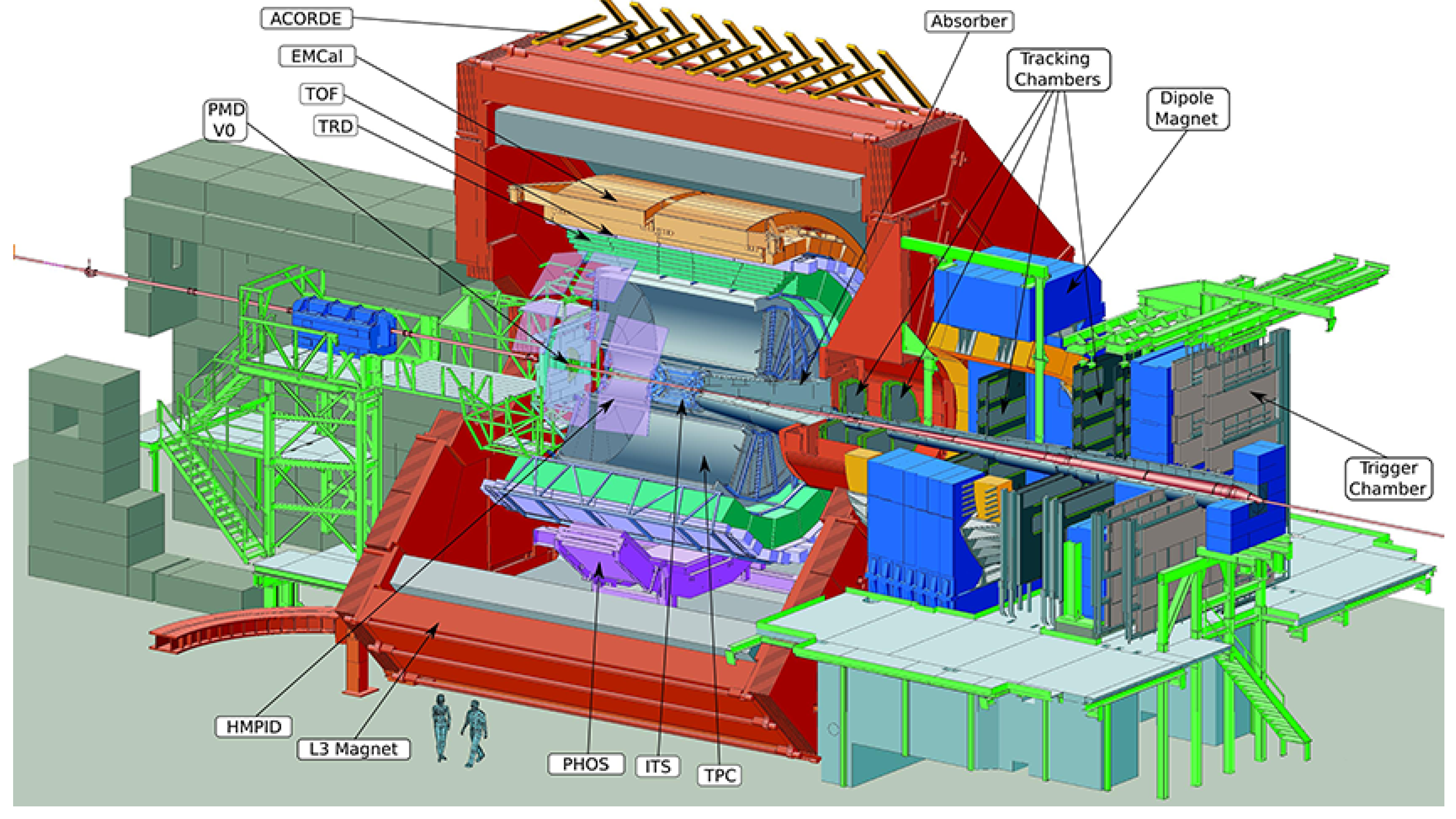
The ALICE experiment at CERN (
Figure 1) studies ultra relativistic collisions of heavy nuclei at the Large Hadron Collider at CERN [
2]. During these collisions, a new phase of matter called quark–gluon plasma is created. Collisions in the LHC generate temperatures over 100,000 times hotter than the centre of the Sun and give birth to thousands of new particles. A large camera with a size of 16 × 16 × 26 m
and mass of more than 10,000 tons surrounds the collision point and measures the parameters of created particles. Different detector technologies including silicon sensors, scintillators and gas detectors are deployed to detect the type, energy and trajectory of the particles.
The experiment is currently undergoing a massive upgrade to cope with an increase of collision rates by two orders of magnitude. New detectors were developed and readout electronics have been upgraded. The new conditions will result in the increase of generated data from an original value of 2.5 GB/s up to 4 TB/s. This data are transported by 9000 optical readout links to an online processing computer farm [
8].
The requirements of LHC experiments for high speed transfer of large data volumes led to the development of a radiation-hardened link. The GigaBit Transceiver (GBT) developed at CERN allows for bidirectional data transfer at 4.8 Gb/s [
9]. In addition, a dedicated ASIC called the Slow Control Adapter (SCA) was developed for the distribution of control and monitoring signals on the front end electronics modules [
10]. The SCA is part of the GBT chip set and allows for transmission of control signals in dedicated bits reserved in the link data frames. The SCA communication occurs in parallel to data-taking. The bandwidth provided to SCA is sufficient for most controls’ applications; however, certain detectors require a higher throughput. This requirement is addressed in the Single Word Transaction (SWT) protocol, which interleaves readout data frames with frames containing only controls data. Large differences in detector architectures in ALICE required the implementation of additional protocols via the GBT.
The presented FRED framework addresses the task of providing infrastructure that integrates all deployed protocols and exposes them via a common interface to the upper layers of the controls hierarchy. The presented architecture provides a clear separation of control tasks into several layers, described in the following chapters.
As already mentioned, after the upgrade, there will be much larger amounts of data to process including many more communication channels with new detector electronics. The WinCC OA system itself does not have enough computational power to process such a large amount of incoming data while controlling all detector electronics. One of the possibilities would be to enlarge the size of the controls cluster. The increase of the system complexity would require a substantial growth of the controls cluster, already consisting of 200 powerful servers. Besides the cost implications, more manpower would be needed for the server maintenance and operation. Adding the FRED framework as an additional software layer to the new architecture addresses the issue, since all computationally expensive operations including monitoring, data retrieval, and control of large amounts of electronics are carried out by FRED. This way, certain resource demanding operations will be delegated from WinCC OA to FRED, resulting in significant savings as fewer machines are required to run the entire system.
3. ALFRED Architecture
One of the novel detectors installed during the ALICE upgrade is the ITS (Inner Tracker System) [
11]. It is made of 25,000 pixel sensors covering 10 m
area with a total number of 12.5 billion active pixels [
12]. The control of the electronics is achieved via the newly developed FRED framework described in this paper. To understand the role and place of FRED in the controls hierarchy, we must first describe the control system architecture of the ITS.
The Detector Control System (DCS) is used to monitor, control, and ensure the safe operation of the detector [
3]. It consists of several subsystems, each providing certain functionality such as low voltage power, high voltage, cooling, gas circulation, or front-end electronics access. The DCS systems are specific to each detector, although the conceptual architecture is still the same. At the upper level, the commercial SCADA system WinCC OA is used [
13]. The WinCC OA systems are configured as distributed systems sharing the control and data flow for each detector. The cluster of central SCADA systems integrates all detector systems into one big distributed system, controlling the whole experiment.
The new ITS detector is equipped with such a system, following the standards deployed in ALICE over past 12 years of its operation.
Figure 2 shows a schematic representation of the ITS detector control system. It consists of four basic subsystems that are connected directly to the central DCS—Frontend System, Power System, Detector Safety System, and Cooling System.
The Power System provides stable power to the detector electronics as well as the detector itself. It is based on commercial power supplies developed by CAEN SpA that are interfaced via OPC servers [
1]. The CAEN supplies are used to directly power the Readout Units and Power Boards—the basic front-end electronics modules of the ITS. Since detector powering requires delicate voltage settings, the detector is not powered directly from CAEN supplies but from the Power Boards. The Power Boards can be controlled by the Readout Units, allowing the Frontend System to make adjustments to the power of the detector. Power Boards are also used to monitor the temperature of individual parts of the detector through a set of connected Pt100 sensors.
The Cooling System provides continuous cooling of the detector, thus protecting the detector from overheating and irreversible destruction of detector pixel sensors.
The Detector Safety System provides a hardware interlock to protect the detector. It consists of several PLCs, which have independent temperature sensors placed on the Staves of the detector. If the PLC detects a significant increase in the temperature of the Stave, it triggers a hardware signal that immediately turns off the CAEN power supplies and thus prevents the detector from being destroyed. This system serves as the last protection of the detector if the software interlock system did not respond. In principle, the safety system is not part of the DCS; it is built as an autonomous system but is interfaced with the DCS for monitoring purposes.
The Frontend System provides control and monitoring of the detector and facilitates communication between FLP (First, Level Processor) computers and the central DCS system. The Frontend System is implemented by several FRED (Front End Device) server applications that communicate with detector electronics via ALF (ALICE Low Level Frontend) server applications running on FLP computers. This part of the DCS system is collectively referred to as the ALFRED system [
14].
The FLP servers host several CRU (Commom Readout Unit) cards, and provide splitting of data transferred over GBT links from the detector electronics into physics and DCS data. The physics data are further sent to the O2 (Combined Online Offline) cluster, which tackles the physics processing [
15]. DCS data, stripped from the GBT stream, is forwarded to the DCS Frontend System.
The CRU cards are dedicated PCI express cards developed by the ALICE collaboration that are connected to the Readout Units via an optical GBT (Gigabit Transceiver) link [
16]. Two basic types of protocols are used for the communication with the ITS Readout Units: SCA (Slow Control Adapter) and SWT (Single Word Transaction). The SCA protocol is standard for all the SCA chips embedded on the detector electronics and is supported by each detector. It profits from dedicated bits in each GBT frame and serializes the communication between the SCA chip and controls software. To cope with the throughput requirements of the ITS, the SWT protocol carries more data by using a full dedicated GBT frame.
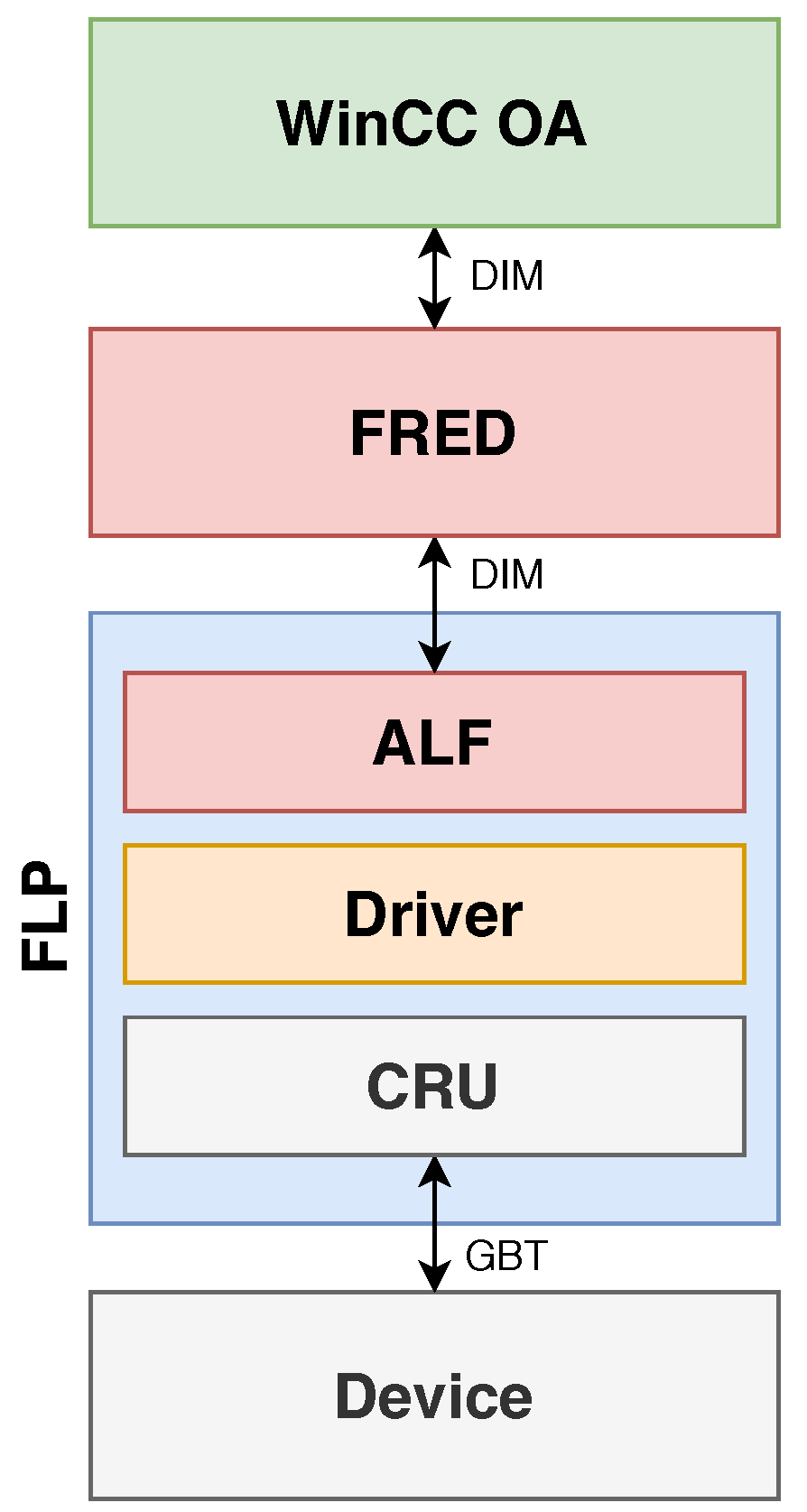
Within the ALFRED architecture, ALF operates as a simple broker that provides access of the CRU driver to remote processes. ALF does not perform any operations with the data, but only serves as an interface between the DIM network protocol and the detector electronics, see
Figure 3. It also ensures atomicity of access to the driver, which ensures transmission of the sequence of commands as a whole and prevents conflicts in case of simultaneous requests from multiple remote processes.
For the ITS detector, a backup communication channel via CANbus has been implemented, which directly connects the Frontend System with Readout Units. This communication channel serves as a bypass in case the FLP computers are unavailable. It is also used for independent monitoring of the detector temperatures that are critical parameters for the detector safety. During the commissioning phase of the detector, the temperature values are fed into a software interlock system. If the CANbus chain is used, FRED communicates with Readout Units using the CANALF (CANbus ALICE Low Level Front End) application instead of the standard ALF application. CANALF provides the same functionality as ALF, but instead of CRUs with GBT links, it uses CAN controllers with CANbus to transfer the data. This example demonstrates the flexibility of the framework. The same FRED can communicate over two fundamentally different buses without the need to change any code of FRED. ALF provides the necessary transparency and hides low level transfer details from the control logic.
4. FRED Architecture and Capabilities
The FRED server application is a key component of the DCS architecture of the ALICE experiment [
14]. It provides translation of raw data obtained from the detector electronics into the format of physical quantities (such as voltages, currents, temperatures, etc.) that are necessary to ensure the continuous operation of the detectors. It also provides the mechanisms necessary to implement detector monitoring, control, and protection systems. At the same time, FRED is designed to make it easier to implement detector operations using configuration files without the need for any programming. The development of the FRED application has continued intensively in recent years, while its functionality has been modified and extended on the basis of new detector requirements, while continuously adapting to the gradually delivered detector electronics.
For communication with other processes, FRED uses the DIM communication system. DIM is a communication system for distributed environments provided by CERN that provides network-transparent inter-process communication [
17]. It uses the TCP/IP protocol and is based on the client/server paradigm. The basic concept of DIM is that there are services provided to clients. DIM uses the DIM Name Server (DIM DNS), so that clients do not need to know the IP address or domain name of the server, but it is enough to have information about the names of DIM services. DIM provides two basic types of communication: the first is the publish/subscribe concept, where the clients subscribe to information published by the server, and the second are the RPC services, where the clients send a request to the server and the server sends back a response [
18].
For the communication with ALF servers, FRED uses DIM RPC services. After sending a request to ALF, FRED waits for the command to be processed and the response received. This mechanism ensures the atomicity of executing commands for the electronics, as during the ongoing DIM RPC transaction all other RPC requests for those electronics are waiting for the current transaction to be completed. To communicate with the superior WinCC OA system, FRED uses DIM publish/subscribe services. FRED subscribes to the DIM services provided by the WinCC OA system while publishing monitored or status information about the detector. This principle ensures asynchronous communication with the WinCC OA system.
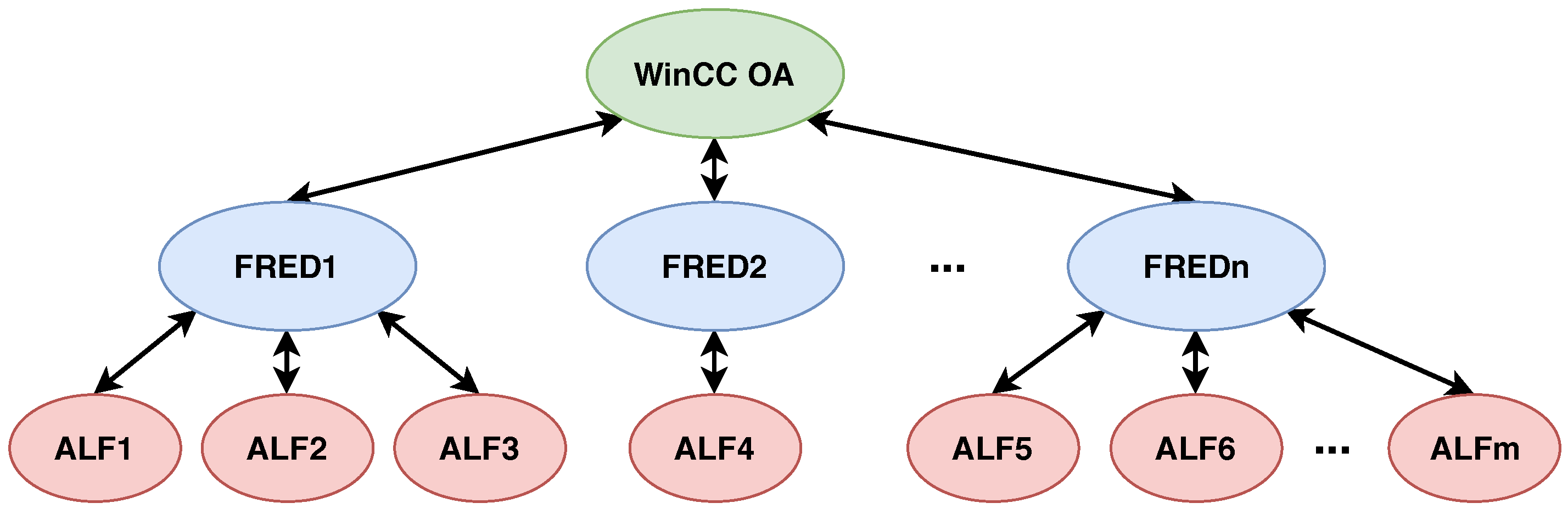
FRED is designed to work with multiple ALF servers, where the number of ALF servers is limited only by computational resources of machine and network bandwidth. This capability ensures that one instance of FRED can control a large amount of electronics of the detector. Furthermore, one WinCC OA system is able to manage multiple instances of FRED, making it possible to build large distributed control systems based on the ALFRED architecture, see
Figure 4.
To ensure the atomic execution of command sequences for electronics, FRED has several queue objects. Queues ensure execution of the entire sequence as a whole, so all other requests are suspended while the current sequence is being executed. This mechanism serves as a protection against the execution of competing sequences where one might affect the outcome of the other. When initializing FRED, one queue is created per one link, i.e., one part of detector electronics. At the same time, queues ensure the temporary storage of incoming requests as, due to the asynchronous principle of communication with WinCC OA, multiple requests may be received at one time, while all requests must be executed sequentially.
All requests are initiated by the supervisory WinCC OA system. FRED subscribes to the services published by the WinCC OA system, and upon receipt of the request it is processed in the callback function of the specific DIM topic. The request may be empty or may contain the data necessary to generate a sequence of commands for the detector electronics. In the case of using FRED in simple mode, the request may contain information in a defined format, which is then parsed to a sequence such as the required voltages or other electronics parameters. If the MAPI (Message Application Interface) is used, the message may contain data in any format, as this request is processed in objects created for the specific detector requirements.
After reception of a request from WinCC OA, FRED generates the resulting command sequence for the detector electronics. FRED supports three basic sequence types: SCA, SWT, and IC. The SCA transactions are used to control the SCA chip on the readout electronics. The SWT transactions are specific for some detectors, like the ITS or MFT (Muon Forward Tracker). The IC transactions are equivalent to the SCA, but use a different communication protocol. The basic principle of sequence generation is to use a predefined sequence template into which the required information is parsed (usually information obtained from a WinCC OA request or information obtained from a configuration database). Parsed information can still be pre-processed using defined functions, the same that are available when translating real physical quantities into raw data. The generated sequence is then sent to the desired ALF corresponding to the specific detector electronics, and FRED then waits for the response to be received.
As already mentioned, the information necessary to generate the resulting sequence can be obtained from the configuration database. FRED has a built-in interface to access the ORACLE configuration database. The versatility of this interface gives individual detectors the ability to work with configuration data that includes the required electronics settings or procedures for specific detector operations. FRED also provides the ability to move its entire configuration to the database, which is a requirement for the run phase. For testing and debugging purposes, FRED still supports the ability to use local configuration files.
FRED also provides the ability to process data received from ALF as a response to the sent sequence of commands. Based on the FRED configuration, the response to each sequence command can be used to calculate a real physical value, which is used in the case of detector status monitoring. FRED also provides a polling mechanism that allows a portion of a defined sequence to be executed until the specified condition is met. This functionality is used, for example, in the case of on demand ADC measurement, when it is necessary to wait for the completion of the measurement. If the MAPI is used, the response can be processed in any format as the result depends on the code defined by the detector. In any case, after the post-processing, the message is published using DIM services and can be obtained by the WinCC OA system.
Even though FRED was designed specifically for the ALICE Detector Control Systems, it can be easily implemented in any Distributed Control System that uses standard SCADA systems and custom electronics. The required modifications of the ALFRED system relate mainly to the ALF module, which has to be modified to be able to communicate with a new type of electronics in terms of the communication interfaces and protocols. Developers then have to create a respective configuration of FRED, based on the required operations with the electronics. After these modifications, FRED is ready to be used with any standard SCADA system that includes the DIM (open source) communication framework.
There is one more modification needed to use FRED with other SCADA systems that do not support the DIM protocol. To use another protocol for communication with the SCADA system, the communication wrapper of FRED has to be changed. However, no extensive programmatic interventions are needed, since the replace functions for subscribing and publishing data with functions related to the required communication protocol are enough. As an alternative to the DIM communication protocol, one can think about OPC (Open Platform Communications) which is supported by most of the SCADA systems or the MQTT (Message Queuing Telemetry Transport) which uses the same principles as DIM.
Usage of the FRED framework within large Distributed Control Systems can be quite profitable even in industrial solutions. Mainly when it is required to connect a large number of sensors or any custom electronics to the SCADA systems, FRED can be very useful by means of reducing computational load of the SCADA systems, since the computationally expensive operations can be implemented directly in FRED. The level of abstraction provided by FRED also removes the need to modify a SCADA system in case of replacement of the electronics for another type, as long as modification of the ALFRED system is sufficient and the new type of electronics can appear the same to the SCADA system.
4.1. FRED Configuration
The new FRED configuration consists of several parts, most of which are used to run FRED in simple mode, so they are not mandatory when using only MAPI. To run FRED, it is necessary to define the main configuration file, which must contain at least the DIM DNS under which FRED should run and a name for the FRED server process, which must be unique for the given DIM DNS. If the ORACLE configuration database is used, this file must also contain the information needed to connect to the database, such as name, password, and connection string.
The next part of the FRED configuration is the section and board files. Section files are used to define DIM topics published by FRED and their mapping to real hardware via ALF links. They also provide the ability to group multiple topics, making it possible to call a single topic to perform a specified operation over a larger quantity of hardware, such as one whole part of the detector. Section files also allow masking part of the hardware that is not available, for example to exclude a part of the detector from monitoring. Board files can be used to define the behavior of individual FRED topics. They contain paths to necessary command sequences, input and output variables of sequences, or functions for calculating the resulting value when reading data from electronics. The use of these files is useful for development and debugging, but in operation it is recommended to retrieve these configuration parameters from the configuration database.
When using FRED in its simple mode, the command sequences for electronics are generated based on sequence template files. These files may contain the complete sequence required for a given electronics operation, or some parts may be replaced by input variables or a combination of equations and input variables. In this case, the sequence is completed based on the data received from the WinCC OA request, which may contain e.g., the required voltage for the electronics output. This value is then converted to a raw value using the defined equation. The raw value is then parsed to a sequence which is then sent to the desired ALF link.
It is also possible to define output variables in sequence template files. After executing the generated sequence, the resulting values are stored in given variables, which can be sent in response to the WinCC OA system. The output variables can also be used in the equation to calculate the resulting value. In this case, the calculated value is sent in response to the WinCC OA system instead of the raw data obtained after the sequence execution.
Equations used with input and output variables can contain a wide range of mathematical and logical operations. Since the input variables are used to generate the raw sequences sent to detector hardware, the result of a defined equation is rounded and trimmed to a specific length. The result of the equation using output variables is not rounded and is sent to the WinCC OA system as a decimal number.
4.2. Simple FRED and iMAPI
Using FRED in simple mode is an easy way to create a system for monitoring and controlling detector electronics without the need for any additional programming. Using the aforementioned configuration files, it is possible to create FRED topics for executing the desired sequences with the possibility of dynamically adjusting the electronics parameters based on the data received from the WinCC OA system. Thanks to the translation of messages in FRED, WinCC OA doesn’t need to have any knowledge of the real arrangement of electronics, but it is sufficient to know the logical layout of the hardware and the real values of physical quantities. An example of usage of the simple mode FRED is the monitoring system for the ITS interlock system that is currently deployed.
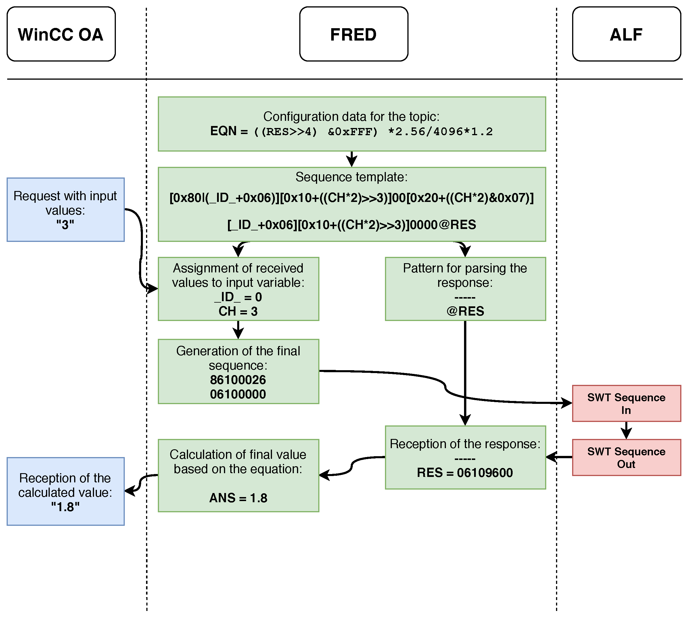
Figure 5 shows a flowchart of the WinCC OA request processing when using FRED in simple mode. When started, FRED loads the configuration files, including files containing predefined sequence templates. After receiving the request from WinCC OA, it parses the received input parameters into a predefined template sequence and generates the resulting sequence, which it sends to the desired ALF node. The response returned from ALF is then parsed based on the pattern of output variables in the template sequence. In case the configuration also contains an equation for processing the output data, the result of the operation is calculated based on the entered equation and the data received from ALF. The calculated result is then sent in response to WinCC OA.
An example of using FRED in simple mode can be reading the temperature from the detector’s power electronics. The temperature reading operation consists of three parts—starting the A/D conversion on the selected channel, waiting for the measurement to finish, and reading the value obtained by the A/D conversion. In the FRED configuration, it is necessary to define a template sequence of commands for the temperature read operation and an equation for converting the raw value of the A/D conversion to a real temperature value. In this case, the input from WinCC OA is simply the number of the desired ADC channel of the particular temperature sensor. Upon receiving a request from WinCC OA, FRED generates the resulting sequence and sends a command to the ALF that will perform an A/D conversion. Subsequently, the polling mechanism determines whether the conversion has been completed or is still in progress. After the conversion is completed, it sends a command to read the temperature value from the relevant register of the electronics. The value is read and then converted to the real temperature value based on the defined equation. This calculated value is then sent as a response to WinCC OA.
This example also shows the abstraction provided by the FRED framework. The SCADA system has no knowledge of the type of electronics or the format of commands used to communicate with the electronics. The SCADA system only sends a request, which may contain parameters for a more detailed specification of the requested operation, and in response it receives the real value of the physical quantity obtained from the concerned electronics.
The MAPI interface (Message Application Interface) has been implemented in FRED to perform more complex operations with the detector. This interface gives programmers the ability to use their own code, which is executed when calling specified FRED topics. The MAPI provides two basic functions for data processing. The first function is executed upon receipt of the request from the WinCC OA system, where it is possible to perform the necessary operations to generate the sequence for the electronics based on the data received in the request. The second function is executed upon receiving the response from ALF and can be used to process the response from the electronics. The result of this function may be sent to the WinCC OA system.
Some operations with the detector require iterative execution of the sequence or a part of it, but such a procedure could not be implemented using either the simple FRED or the MAPI. For this reason, the standard MAPI has been extended to iMAPI (iterative MAPI), which allows for the execution of complex iterative procedures. The principle of the iMAPI functionality is that, after receiving a response from ALF, it can be programmatically decided whether the execution of sequences should be terminated or not. In this way, it is possible to perform a sequence, iterating until the desired condition is met.
Figure 6 shows the principle of the iMAPI operation in the data processing flow within FRED. The user code can be implemented at two locations within a single iMAPI instance, the PIM (Process Input Message) and POM (Process Output Message) blocks. The left part of the figure shows the data flow in iMAPI if the command requires access to the hardware via ALF. After receiving the request from the WinCC OA, the PIM program block is executed, which is used to generate the required sequence of commands for the electronics, and then sends them to ALF. After receiving the response from ALF, the user code block of the POM is executed, where the electronics response can be evaluated, processed and the result sent to the WinCC OA system. If the electronics response does not satisfy the required condition, it is possible to generate a new request from the POM block, which is then sent to the PIM block, and thus iterate the entire process of sending requests to the electronics until the required condition is met.
If there is no need or possibility to generate a sequence for the electronics based on the received request, it is possible to switch the iMAPI to the mode shown in the right part of the figure using the noRpcRequest flag. In this mode, it is possible to generate an answer or error message in the PIM block even without communicating with the electronics, and then send that to WinCC OA as a response. This mode is mainly used when it is necessary to dynamically change the required FRED settings that are not directly related to electronics.
An example of the use of iMAPI is the voltage drop compensation on detector electronics. When the detector power is turned on, the increase in current results in a voltage drop which can be compensated for by increasing the supply voltage based on the current. The set voltage can be changed by sending a specific sequence to the detector electronics. In this example, upon receiving a request from WinCC OA to set the desired voltage, FRED iteratively obtains the actual voltage and current of the electronics, updating the set voltage based on the calculated value. This cycle is repeated until the difference between the actual and the desired voltage is lower than the defined threshold.
5. System Performance and Scalability
After the upgrade, the individual detectors of the ALICE experiment will continuously produce much larger amounts of data than during Run 2 [
19]. This implies that the DCS system must also be able to process a large amount of data in real time. Since the ALFRED system is a key part of the DCS system, it was necessary to test its capabilities in terms of performance, throughput, and the amount of data processed.
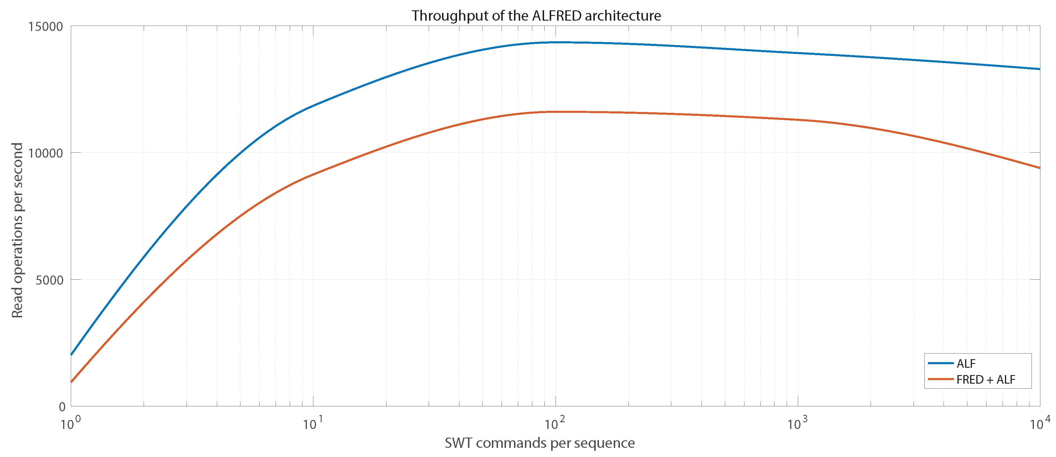
Two types of tests were performed to determine the overall throughput of the ALFRED system. In both cases, the tests were performed to determine the maximum number of read operations of data from detector electronics that can be performed in one second. The first set of tests was performed using only an ALF server and detector electronics in the chain. The second set of tests also included the use of the FRED server together with the ALF server. For these test purposes, the ITS Readout Unit was used as an instance of detector electronics.
Figure 7 shows the results of tests of the ALFRED system throughput. As can be seen, the throughput of the system increases with the increasing number of commands in a single sequence, due to the diminishing influence of the DIM overhead, as the sequence is always sent as a whole by the DIM protocol. Maximum system throughput is achieved if the sequence contains approximately 100 commands, where ~14,400 register readings per second can be achieved using the ALF server and ~12,000 register readings per second can be achieved using the FRED server together with the ALF server. As the number of commands in a given sequence increase, the throughput decreases slightly as the time to process the larger sequence increases.
Test results indicate that the ALFRED system has sufficient speed and throughput for use in the DCS systems of all ALICE detectors. By optimizing the length of the sequences, it is possible to achieve maximum throughput of the system, which at the same time provides a sufficient margin in case of the occurrence of errors or unexpected situations that may occur during detector operation.
Although FRED adds noticeable overhead to the command sequence processing time, as can be seen in
Figure 7, its use has a positive effect on the amount of data processed by the DCS system. Without the use of FRED, the WinCC OA system would have to take care of communication with ALF servers, it would have to generate command sequences for the electronics, while also handling all monitoring and control of the detector. The current WinCC OA system would not be able to handle this amount of processing, since after the upgrade of the ALICE experiment, the flow of data from the detector electronics will be overly increased. For example, the ITS detector alone will include ~25,000 sensors and the DCS has to monitor multiple parameters of each sensor. In this case, FRED also serves as a filter: while it processes all the data, only values that require additional processing, e.g., archival or alert handling, are published to WinCC OA. Thus, FRED has a positive effect on the total amount of data processed, as it significantly relieves the WinCC OA system from the computationally expensive operations with the detector electronics.
The ALFRED system is designed as a massive distributed system, which provides the possibility of parallel monitoring and control of individual detector parts. As an example of the scalability of the ALFRED system, we can point out the interlock system of the ITS detector. The Interlock system monitors the temperatures of all 192 Staves and 282 Power Units of the ITS detector. For monitoring, there are 22 instances of CANALF used with two instances of FRED. In this configuration, the ALFRED system satisfies all requirements for the monitoring and interlock of the ITS detector.
6. Implementation of FRED in ALICE
Over time, the ALFRED architecture, along with the FRED application, has become the standard for the DCS systems of the ALICE experiment detectors. One of the DCS subsystems that already uses the ALFRED architecture is the ITS software interlock. As already mentioned, the software interlock ensures that the detector’s power is turned off if any of the monitored temperatures exceeds the critical value, if the monitoring fails to get a valid measurement, or if the Readout Unit stops responding completely. The ITS software interlock is divided into two parts, one operating the Inner Barrel and another operating the Outer Barrel of the ITS.
The software interlock system is the first complex system in ALICE that is implemented using the new FRED framework, which will be used within the surface commissioning of the ITS detector. In this example system, FRED is used to monitor all the 282 Power Units of the ITS detector including the 846 temperature sensors in parallel. This example shows that only the two instances of FRED are able to handle monitoring of all the electronics of the ITS detector. The tests have shown that one instance of FRED would be sufficient for the software interlock system, though two were used to logically separate the system for the Inner and Outer Barrel of the ITS. The example also shows the flexibility of the FRED framework, since it uses the CANALF instead of the ALF to communicate with the electronics. CANALF is simply a modified version of ALF that is able to communicate with the electronics using CAN bus instead of the GBT link. Even though it uses a different communication interface with a different protocol, FRED is still the same with no modification when compared to FRED as used with ALF.
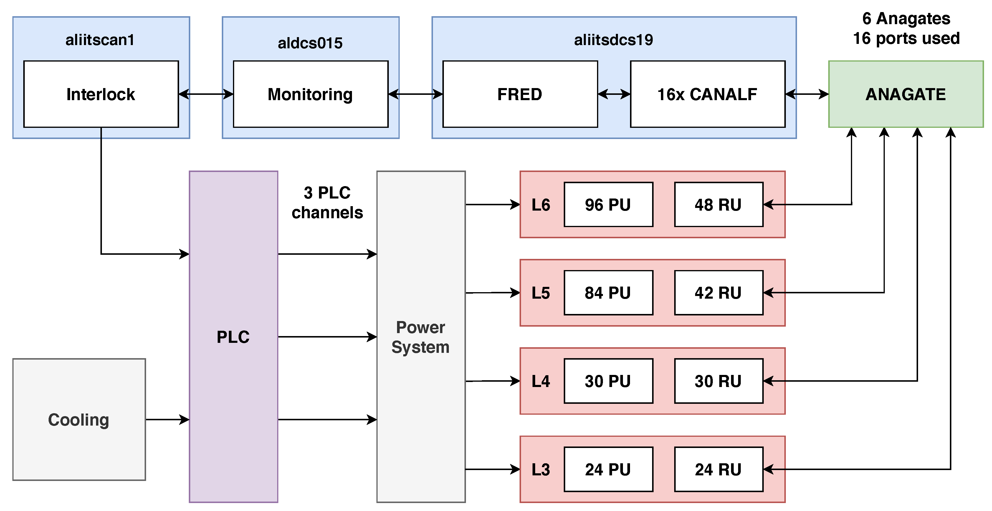
Figure 8 shows a schematic of the software interlock system for the Outer Barrel of the ITS. Both Inner and Outer Barrel of the ITS detector are organized to several layers of Staves containing silicon pixel chips. The Outer Barrel includes detector layers L3, L4, L5, and L6, each of which is connected to a corresponding Power Unit and Readout Unit. In layers L5 and L6, two Power Boards belong to one Stave because of the larger number of pixel chips that need to be powered.
Each Readout Unit is connected to one of the 16 CAN buses that are served by 6 AnaGate gateways. Each CAN bus is served by a separate instance of the CANALF application, allowing parallel reading of data from each CAN bus. All instances of CANALF are connected to a single instance of FRED, which contains predefined sequences for reading temperature, voltages, and currents and publishes the DIM topics associated with the specific Power Units of the system.
The Monitoring project is a WinCC OA application that provides temperature monitoring at the required intervals. Tests have shown that monitoring of all 702 temperature values from all 234 Outer Barrel Power Boards can be performed at frequencies up to 5 Hz, while the detector requirement is 1 Hz for monitoring. It was also found that the limiting factor in the monitoring frequency is the speed of the CAN bus.
The Interlock project is another independent WinCC OA application which generates a Heartbeat signal for connected PLC channels. At the same time, the project receives the monitored temperatures from the Monitoring project and stops generating the Heartbeat if the acquired temperature has exceeded a critical value or one of the Readout Units has stopped responding. Heartbeat generation is automatically resumed if the monitored values return to the allowed range.
If the PLC does not receive the Heartbeat signal within the set time (usually 10–15 s), it automatically turns off the corresponding channel, which results in switching off the CAEN power supply for the relevant part of the detector. The PLC also takes into account the signal from the cooling system of the detector, and, if the cooling stops working, the power will also turn off. Individual PLC channels are independent of each other and provide protection for different parts of the detector. The Outer Barrel uses three PLC channels, the first serves layers L3, L4, and L5, the second serves the L6 TOP half-layer and the third serves the L6 BOTTOM half-layer.
The tests have shown that adding more electronics in parallel, i.e., connecting more CANALF instances to FRED, has no impact on the performance of the whole setup. FRED is able to handle the monitoring at the same readout period as with fewer electronics, which points to the ability of FRED to process large amounts of data in parallel without losing performance, unlike the SCADA systems.
7. Conclusions
The FRED framework described in this paper fills a gap between custom electronics and industrial SCADA systems. It provides flexible and versatile tools for interfacing nonstandard devices with applications adhering to industrial standards. The separation of front-end electronics access into two parts—ALF and FRED—allows for abstraction of the device model and provides a uniform interface to any device type with interfaces based on register access. The communication protocol implemented between ALF and FRED is based on an open software toolkit (DIM) developed at CERN and ensures command atomicity as well as the possibility to distribute the components over several control computers. This mechanism provides an efficient way of managing resource utilization, as well as the flexibility to add new devices or move existing devices across the setup.
In the given example, DIM is also used for communication between FRED and its supervisory SCADA system. Even if DIM implementations are supported on a large set of platforms, this is not the only possible way to communicate with FRED. The FRED architecture and separation of the device logic from data and command transport allows for further extension and changes in the top level communication. The possibilities cover all standard protocols, including the industrial standards like OPC, and open the door for a wide range of applications that could profit from the FRED architecture.
In the described application, we focus on the implementation of FRED in the ALICE experiment at CERN. The ITS detector was described in detail, but currently FRED is used in all upgraded ALICE detectors and has become a controls standard. In addition, a FRED-based application is used for the interlock system deployed in the commissioning lab of the ITS detector.
Encapsulating low-level device access in ALF, and all device logic in FRED, provides a sustainable solution for setups requiring long term support. Clear separation of the device logic from the communication protocols allows for flexible upgrades and simplified maintenance.


