Article

Combined Analysis of Parameter Sensitivity and Exergy for Natural Gas Liquefaction in Cryogenic Fuel Production Process

1
Marine Engineering College, Dalian Maritime University, Dalian 116026, China
2
International Center on Energy Sustainable Ships and Ports, Dalian 116026, China
*
Author to whom correspondence should be addressed.
Processes 2020, 8(5), 561; https://doi.org/10.3390/pr8050561
Submission received: 15 April 2020 / Revised: 29 April 2020 / Accepted: 6 May 2020 / Published: 10 May 2020
(This article belongs to the Special Issue Thermodynamics: Modeling and Simulation)

Abstract

:
Compared with conventional natural gas, liquefied natural gas has the advantages of easier storage and transportation, more safety, less indirect investment, better peak regulation, and environmental protection. This paper studies the large-scale cryogenic propane precooled mixed refrigerant (C3MR) liquefied natural gas (LNG) process. The phase equilibrium of the liquefaction process is calculated by the Peng-Robinsonstate equation using ASPEN. A numerical model for the thermal process simulation of the liquefaction process is established by MATLAB. Based on Active X technology, data invocation between software is realized, which overcomes the problem of process variable changes under limited degrees of freedom. The minimum sum of the propane precooling amount for the compressor energy consumption is used as the objective function, the control variate method is used to address the liquefaction process model, and the parameter sensitivity analysis is performed and combined with the exergy analysis. The effects of multiple parameters (e.g., the pressures and temperatures) on the process performance are analyzed and discussed. The results indicate that the combined analysis of the parameter sensitivity and exergy adopted in this paper are able to increase the system performance and reduce the exergy loss of equipment. The maximum reduction of the throttling loss of the process is 60.14%, and the total exergy loss is reduced by 25.8%.

1. Introduction

“Safe, efficient and low-carbon” development and use of energy have become the consensus of countries around the world. Natural gas (NG), as a kind of high-quality, clean, and efficient energy, is generally valued and exploited by various countries. To facilitate the transportation and storage, NG is usually cooled to around 112 K and then throttled down to atmospheric pressure to become a liquid, called liquefied natural gas (LNG) [1,2]. Its density is more than 600 times that of standard methane, and its energy density by volume is 72% that of gasoline. LNG is not only a solution to the transportation and storage of NG, but also widely used in NG peak installations to reduce the peak energy situation in cities [3]. During the extraction, liquefaction, storage and transportation of NG, its liquefaction production process accounts for more than 30% of the energy of the entire life cycle [4]. This is because this process is a cryogenic process which usually includes both the gas liquefaction and separation. In order to provide a cooling capacity far below the normal temperature, it usually requires a large amount of energy consumption [5]. Therefore, it is essential to conduct in-depth research to improve the energy efficiency of cryogenic processes and avoid energy waste.
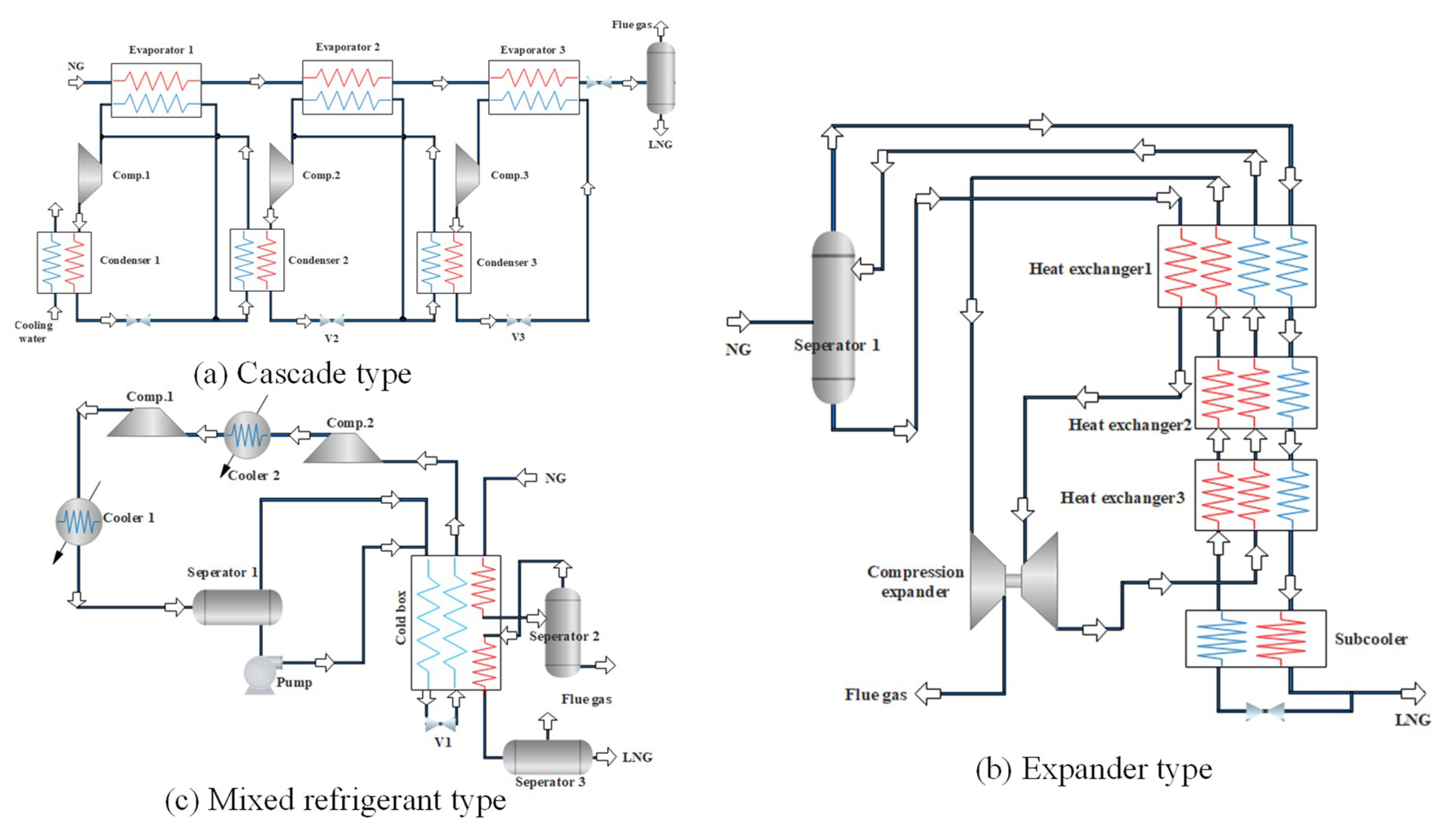
As shown in the Figure 1, the NG liquefaction process can be divided into three major forms: cascade type [6,7], expander type [8,9], and mixed refrigerant type [10,11]. The cascade type is the earliest form of the NG liquefaction process application. It consists of three refrigeration cycles of C3H8, C2H4, and CH4. Each sub-cycle has a compressor evaporator, condenser, and throttling device. It has the advantage of low energy consumption with pure refrigerants, and is free of matching problems, while its disadvantages are also significant, due to the complex process and equipment. The expander type uses expansion refrigeration to realize the liquefaction. Depending on the refrigerant, it can be divided into a nitrogen expansion, a nitrogen-methane expansion, and a NG expansion liquefaction process. Due to the flexible adjustment, easy movement and quick start-stop, this process is particularly suitable for small-scale skid-mounted or peak-regulated NG liquefaction plants, but its disadvantage is high energy consumption. The mixed refrigerant liquefaction process uses a mixture of C1~C5 and N2 as the refrigerant, and obtains different temperature levels through the stepwise condensation, evaporation, and throttling, by means of which, the NG can be gradually cooled and liquefied. Compared with the cascade type and expander type, the mixed refrigerant liquefaction process has a lower energy cost, simpler processes, and fewer unit equipment, especially for the propane pre-cooled mixed refrigerant liquefaction process (C3MRC) which absorbs the cascade type liquefaction process. This process is simple and efficient, and 80% of the basic load NG liquefaction units adopt the C3MRC process at present.
In 1940, the first NG liquefaction plant was built in the world [12]. Since then, with the increase in energy demand, NG liquefaction technology has greatly developed. Table 1 summarizes different works of NG liquefaction technical research. The main methods used in previous studies are ASPEN PLUS, HYSYS, and MATLAB process simulation software [13,14], optimization algorithms [15,16], or the combination of these two [17,18]. Mafi et al. [19] used a combination of mathematical planning and thermodynamic analysis to optimize the composition and pressure of the mixed refrigerant to minimize the energy consumption of the compressor. The results showed that the mixed refrigerant cycle can improve the thermal efficiency of the refrigeration system. Castillo et al. [20] analyzed different pre-cooling cycles of NG liquefaction processes with the help of HYSYS process simulation software, and the results showed that the three-stage propane pre-cooling had the highest efficiency in the studied cycle. Xu et al. [21] used ASPEN PLUS to optimize the refrigerant composition under different cold box inlet temperature conditions in a single-stage mixed refrigerant NG optimization process. Hwang et al. [22] combined the genetic algorithm with sequential quadratic programming to optimize the parameters of the dual mixed refrigerant process. Khan et al. [23] optimized the single-stage mixed refrigerant NG liquefaction process with the goal of minimizing the energy consumption of the process, and the energy consumption was reduced by 10% compared to the previous optimization. Shirazi et al. [24] used genetic algorithms to optimize the energy cost of a single-stage mixed refrigerant NG liquefaction process and also conducted a detailed evaluation and analysis of the effective energy loss of each device in the process. Primabudi et al. [25] used the exergy analysis model and results to perform a multi-objective optimization of the C3MR LNG process. Without applying any weighted preference to the target, they found the Pareto front of the LNG liquefaction process. Lee et al. [26] used a combination of a nonlinear programming (NLP) model and thermodynamic analysis to comprehensively optimize the mixed refrigerant cycle for low temperature systems. Nogal et al. [27] optimized the mixed refrigerant cycle with multi-stage refrigerant compression, controlled the heat transfer temperature difference of the heat exchanger, considered investment costs, and used the genetic algorithm to obtain the global optimal solution. Wang et al. [28] developed an optimized framework for designing a multi-flow cold box. The optimization framework included a multi-flow matching organization design based on the pinch analysis on the heat exchanger network, field collaborative optimization analysis, and the exchange of temperature fields. A new heat exchanger network was designed for the LNG regasification process using this method to restore the released cooling capacity, forming a compact and highly efficient non-freezing heat exchange system [29]. Vikse et al. [30] used a non-smooth framework to simulate the progress of a non-smooth analysis in the modeling of two different dual mixed refrigerant processes. The results showed that the method could provide an accurate formula to handle complex liquefied gas liquefaction processes and simulate flowchart models by improving a non-smooth equation, rather than only solving local optimization problems. Gu et al. [31] established a co-production process of coal-to-LNG and methanol and simulated key units. After a detailed analysis of the energy cost, 9.3% improvements of energy were achieved for the new process system. Sun et al. [32] proposed a phased superstructure to integrate the energy of the absorption and evaporation processes into the heat exchange network. A mixed-integer non-linear programming model was developed on the basis of the proposed superstructure in order to minimize the total annual costs. The results showed that the new method can recover waste heat from the thermal process stream. Qyyum et al. [33] investigated the uncertainty levels of total energy consumption and minimum internal temperature difference within the LNG heat exchanger, as well as the changes in double mixed refrigerant (DMR) process operating variables. After the global sensitivity analysis was performed, the influence of random operating condition input on process performance parameters was clarified. Wu et al. [34] proposed a new liquefaction process using a brazed plate heat exchanger based on an improved single mixed refrigerant process. Some parameters of the process were optimized by genetic algorithms and highlighted the effect of the heat exchanger. Zhang et al. [35] performed optimization and comparison of four LNG liquefaction processes with expanders to minimize energy consumption and minimize production costs. The results showed that the ammonia pre-cooling cycle could reduce the energy consumption by 26–35% and the production costs by 13–17%, respectively.
In the above literature, from the perspective of energy consumption and economy, although the stepped liquefaction refrigeration cycle has a low energy consumption, the equipment is complicated; while for the expansion liquefaction cycle, although the process is simple, the energy consumption rises. Therefore, in this paper, the stepped cycle and mixed refrigerant cycle are selected to perform a combined propane pre-cooled mixed refrigerant cycle for natural gas liquefaction production. Besides, compared with the pure refrigerant cryogenic liquefaction process, the phase change of a multi-component mixed refrigerant is also a process with temperature changes. Therefore, by rationally optimizing the design process, the temperature-enthalpy curves of the hot and cold fluids could be ideally matched, thereby effectively improving the thermodynamic efficiency of the process. According to the above relevant literature, there are three analysis trends: (1) the relationships between different parameters are usually not considered in the NG mixed refrigerant liquefaction processes, i.e., it is assumed that the other parameters remain unchanged when analyzing the impact of one parameter on the process performance; (2) even through the mutual relationships between the parameters are considered, the process optimization model would be complicated and inevitable to be blind, due to the lack of understanding of the interaction mechanism between these process parameters; (3) commercial software can only solve the problem of total energy balance at the equipment import and export, but it is difficult to solve the problem of process variable changes under limited degrees of freedom. In order to avoid the temperature crossovers and pressure advances, time-consuming iterative and trial-and-error methods are often employed in the process design to find feasible solutions for these problems.
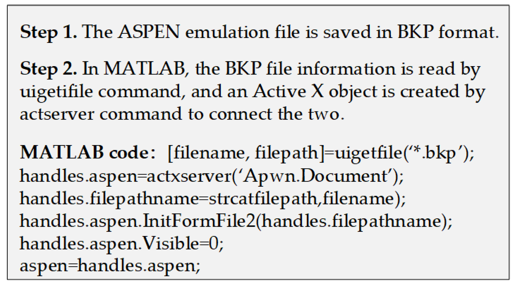
To avoid the inaccuracy of thermodynamic calculation caused by the above assumptions and constraints, this article mainly focuses on numerical simulation and analysis of thermal processes, and modularizes the equipment classification involved in the liquefaction process. It starts from the results of parameter sensitivity analysis, and employs the control variate to recurse until all the best parameters of the process are obtained. There are four major innovations and features in the present study: (1) the stepped cycle and mixed refrigerant cycle are adopted and combined to establish the model of propane pre-cooled mixed refrigerant cycle, and the corresponding exergy analysis is performed on the basis of the thermodynamics and phase equilibrium model with MATLAB and ASPEN; (2) with the aid of Active X technology, data invocation between software is realized to overcome the problem of process variable changes under limited degrees of freedom, which effectively avoids the time-consuming iterative and trial-and-error methods used to find feasible solutions in process design; (3) a single variable method is developed on the basis of the parameter sensitivity analysis to recurse until all the best parameters of the process are obtained; (4) the parameter sensitivity analysis and exergy analysis are combined and adopted to improve the system performance and reduce the exergy loss of equipment.

2. Research Object Description

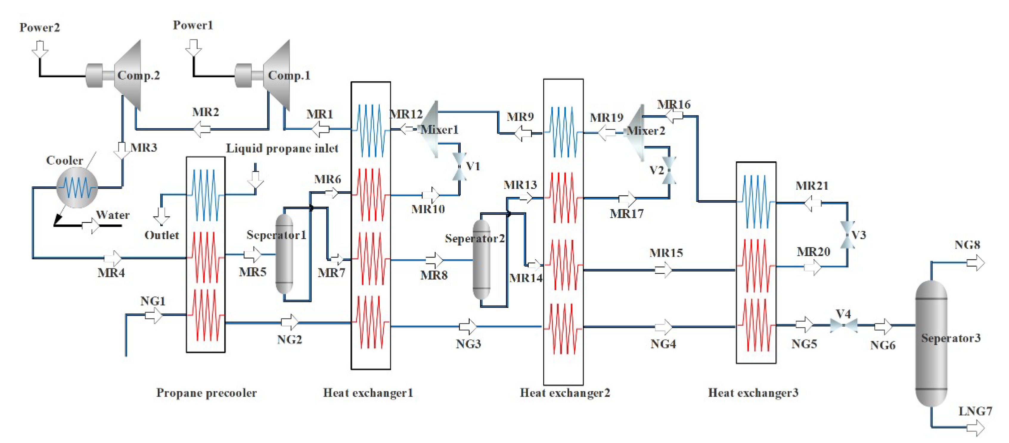
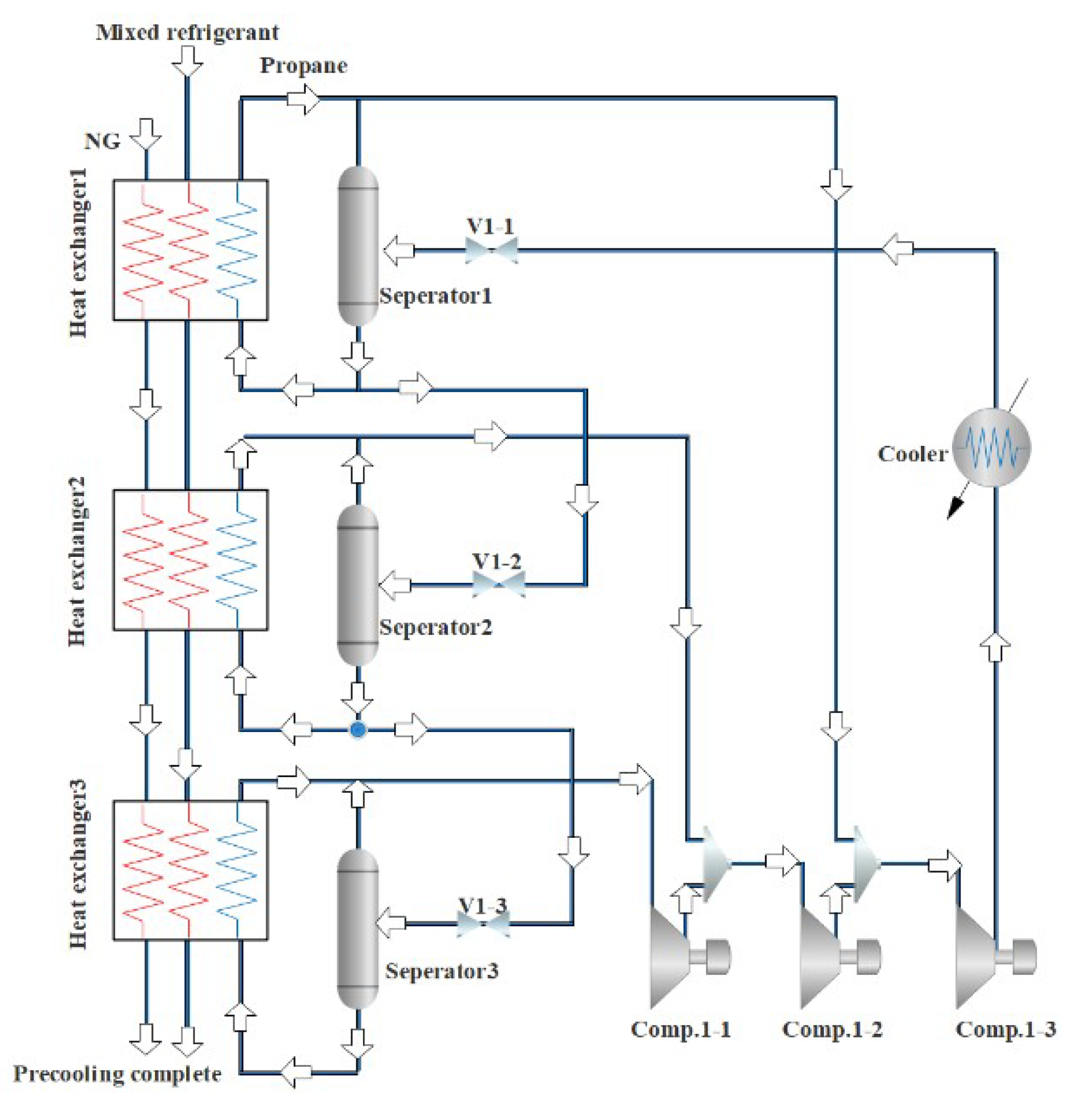
Figure 2 is a NG liquefaction flow chart of the system process. The process consists of three parts, i.e., the propane pre-cooling cycle, the NG liquefaction flow path, and the mixed refrigerant circulation circuit. In this liquefaction process, the propane pre-cooling cycle is used to pre-cool the mixed refrigerant and NG, and the mixed refrigerant cycle is mainly used for the liquefication of cryogenic NG. The detailed process can be divided into three parts. Firstly, a brief introduction to the propane pre-cooling cycle is provided, as shown in Figure 3. Propane passes through three temperature zones in the heat exchangers to provide cooling for NG and mixed refrigerants. The propane is successively compressed by the compressor to a high temperature and high pressure, cooled by the cooling water, passed through a throttle valve to reduce the temperature and pressure, and then produces two phases (i.e., gas and liquid) in a separator. The gas phase returns to the compressor, and the liquid phase is divided into two parts. Part of the liquid is used to cool the NG and the mixed refrigerant, and the rest liquid is used as the refrigerant in the subsequent processes. Since the propane pre-cooling process is an auxiliary process of natural gas liquefaction in this paper, for details, please refer to the literature [36].
Secondly, the propane precooling system is shown in the Figure 2 as a three-step heat exchanger. NG-1 is cooled by the propane pre-cooling, heat exchanger 1 (high-temperature heat exchanger), heat exchanger 2 (medium-temperature heat exchanger), and heat exchanger 3 (low-temperature heat exchanger). Then it is throttled and depressurized by the throttle valve V4, and enters separator 3. Then the normal pressure LNG product is obtained at the bottom of separator 3 for subsequent storage and transportation. Thirdly, the mixed refrigerant is compressed to a high pressure by a two-stage compressor, and it is cooled with water to take away a part of the heat. Then, it is pre-cooled by a propane pre-cooling cycle. After the pre-cooling, it enters gas–liquid separator 1 and becomes the liquid phase and the gas-phase. Heat exchanger 2 is provided with a cooling capacity. The NG and the mixed refrigerant in the gaseous and liquid phases exiting separator 2 are cooled. The gas-phase refrigerant coming out of heat exchanger 1 is cooled by heat exchanger 2 and then throttled and cooled to enter heat exchanger 3 to cool the NG and gas phase mixed refrigerant. The cooling capacity of the above heat exchangers 1, 2, and 3 is provided by a mixed refrigerant cycle consisting of N2, CH4, C2H6, and C3H8. The low-pressure gaseous mixed refrigerant MR1 from heat exchanger 1 is first compressed in the compressor. It is cooled to high pressure by propane pre-cooling to enter separator 1, and then separated into a liquid phase MR6 and a vapor phase MR7 in separator 1. After the liquid phase is produced, MR6 is subcooled by heat exchanger 1, the throttling refrigeration becomes MR12. Similarly, the vapor phase MR14 enters heat exchanger 2 after cooling and liquefaction, subcooling, and throttling cooling. After cooling and reheating, it becomes MR19. Finally, the MR9 is mixed with the previous MR10 into heat exchanger 1 to provide a cooling capacity, and the reheated gaseous mixture MR1 is re-entered into the compressor inlet to complete a refrigeration cycle.

3. Model and Simulation

3.1. Methodology

To correctly obtain the physical parameter at each node in the simulation process, it is necessary to solve the problem of phase balance calculation, and the program can determine the phase state of the fluid in the process during the calculation process. Hence, Peng Robinson’s physical property model and heat-phase balance are adopted from ASPEN. Although the commercial software can solve the total energy balance at the equipment imports and exports, it lacks new calculation methods for the physical property, leading to incomplete unit equipment models and process variable changes under limited degrees of freedom. As a consequence, it often takes a lot of time on the trial-and-error and iteration methods to find feasible solutions and other problems. Therefore, in order to expand the conventional function from ASPEN, the related parameters in the thermodynamic phase balance are transferred to MATLAB for more detailed model analysis, numerical calculation, and data processing.
Active X technology is a system integration protocol based on the Windows platform. It can integrate and exchange data among different open interfaces in different applications to achieve specific requirements [37,38]. Therefore, in this paper, it has been employed to realize the data interaction and transfer between ASPEN and MATLAB to make up for each other’s weaknesses and obtain ideal results for the process design. When the two software are successfully connected, ASPEN can be operated as a background program for MATLAB, where the users can write and read data according to the commands. In ASPEN, the input and output data of previous simulations and calculations are stored in a tree structure macro. It can be directly assigned and read in MATLAB as long as the variable path is known. For details, please refer to Figure A1 in Appendix A, which shows the pseudocode for data interaction connections. By means of the above operations, the stream information and physical property parameters of the equipment involved in the liquefaction process can be directly extracted from ASPEN and then imported into each equipment model in MATLAB for the numerical calculation and exergy analysis to perform the simulation for the whole process. During this calculation process, ASPEN is operated as the back-end toolbox, and MATLAB is used to perform the modeling and export of the related equipment. For the simulation of a specific system, the user can set a loop command statement in MATLAB to carry out a sensitivity analysis on the operating parameters of each device in the liquefaction process and calculate the change trend of each index in the system under different parameters.

3.2. Process Modeling

The compressor is an indispensable device in the liquefaction process. Its main function is to compress the refrigerant in the process, and prepare for the pressure reduction and temperature reduction of each throttle valve in the subsequent process. The known parameters for the compressor module calculation are the pressure at the inlet node, temperature, enthalpy, entropy, molar flow rate, mole fraction in the total flow rate, compressor efficiency, and outlet pressure. After the calculation, the temperature, enthalpy, entropy, gas-phase flow rate, liquid-phase flow rate, total flow rate, liquid-phase mole fraction, gas-phase mole fraction, and total flow rate at the compressor outlet are obtained. For the calculation of the compressor, according to the material balance, one enters the known parameters of the compressor’s inlet and outlet qn,2 = qn,1, z2 = z1, ηc, the pressure at the inlet node and the outlet pressure. The exergy loss of the compressor can be calculated as follows:
Δ E x = E x 1 E x 2 + W c = Q [ ( H 2 H 1 ) + T 0 ( S 2 S 1 ) + ( H 2 H 1 ) / η c ]
where Ex1 and Ex2 are the effective energies before and after the liquefaction compression, respectively; H1 and H2 are the enthalpy values before and after the fluid compression, respectively; S1 and S2 are the entropy values before and after the fluid compression, respectively; Wc is the power consumption; ηc is the mechanical efficiency of the compressor; T0 is the ambient temperature; Q is the flow rate of the compressor.
The throttle valve plays an important role in the liquefaction process. It reduces the pressure of the high-pressure refrigerant compressed by the compressor and generates a temperature drop. To provide the driving force for the transmission of the refrigerant cooling capacity to NG and other refrigerants in the heat exchanger. This process can be described by qn,2 = qn,1, xz,2 = xz,1, and H2 = H1. The exergy loss of the throttle valve is calculated as follows:
Δ E x = E x 1 E x 2 = T 0 ( S 2 S 1 )
where S1, S2 are, respectively, the entropy values before and after the fluid enters the throttle, T0 is the ambient temperature, and Q is the throttled flow rate.
In the mixed refrigerant cycle NG liquefaction process, the role of the logistics mixer is to mix the throttled and cooled fluid in each multi-stream heat exchanger with the returned flow refrigerant in the subsequent process. It has two functions: (a) the refrigerant can be recycled and reused; (b) since the temperature of the returning refrigerant is still low enough to provide cooling capacity for the multi-stream heat exchanger, the cooling capacity of the low-temperature low-pressure refrigerant can be fully utilized. According to the logistics balance theory and energy balance theory, the mathematical description for the fluid after the mixing of the two flows in the logistics mixer can be concluded as follows:
H 3 = H 1 + H 2 ,   q n , 3 = q n , 1 + q n , 2 ,   z 3 = ( z 1 , i × q n , 1 + z 2 , i × q n , 2 ) / q n , 3
where H1 and H2 are the total enthalpies of the two streams at the entrance of the stream mixer, respectively; H3 is the total enthalpy of the mixed stream at the exit of the stream mixer; qn,1 and qn,2 are the molar flows of the two streams at the entrance of the logistics mixer, respectively; qn,3 is the molar flow of the logistics at the exit of the logistics mixer; z1,I and z2,i are the molar fractions of the components at the inlet of the stream mixer; z3,i is the molar fraction of the components at the exit of the stream mixer. The exergy loss of the logistics mixer is calculated as follows:
Δ E x = E x 1 + E x 2 E x 3 = ( H 1 + H 2 H 3 ) T 0 ( S 1 + S 2 S 3 )
where Ex1 and Ex2 are, respectively, the effective energies of the two streams before mixing, Ex3 is the effective energy of the stream after mixing, S1 and S2 are respectively the entropy values of the flows before mixing, and S3 is the entropy value of the fluid after mixing.
The gas–liquid separator is a key device in the process. In the liquefaction process, the liquid phase produced by the gas–liquid separator enters the throttle valve to generate a temperature drop to provide heat to the heat exchanger; while the gas phase produced by the separator provides refrigerant for subsequent processes. In the calculation of the process, it is assumed that the fluid is isothermally and iso-statically separated in a gas–liquid separator. The thermodynamic model of the gas–liquid separator module is described as follows:
q n , l 2 = 0 ,   q n , v 3 = 0 x l , 2 = 0 ,   x v , 3 = 0 q n , 2 = q n , v 2 ,   q n , 3 = q n , l 3 x z , 2 = x v , 2 ,   x z , 3 = x l , 3 T 1 = T 2 = T 3 ,   P 1 = P 2 = P 3
where qn,2, qn,l2 and qn,v2 are the material flow, liquid phase flow, and gas phase flow at the gas phase outlet, respectively; qn,3, qn,l3, and qn,v3 are the flow rate, liquid phase flow rate, and gas phase flow rate at the liquid phase outlet, respectively; xz,2, xl,2, and xv,2 are the molar components of the stream at the gas phase outlet, the molar components of the liquid phase, and the molar components of the gas phase, respectively; xz,3, xl,3, and xv,3 are the molar components of the stream at the liquid phase outlet, the molar components of the liquid phase, and the molar components of the gas phase, respectively; T1, T2, and T3 are the thermodynamic temperatures at the inlet and outlet, respectively; P1, P2, and P3 are the pressures at the inlet and outlet, respectively.
The multi-stream heat exchanger realizes the transfer of the low-pressure refrigerant cooling capacity to NG and high-pressure refrigerant in the process. NG absorbs the cooling capacity and cools down, approaching the direction of liquefaction and increasing the liquefaction rate. The high-pressure refrigerant is partially liquefied after absorbing the cold, so that two phases of gas and liquid can be produced when entering the next gas–liquid separator.
i N C P H i ( T H i i n T H i o u t ) = j n c p C j ( t C j o u t t C j i n )
A P H p = i N C P H i [ max ( 0 ,   T H i i n T p ) max ( 0 ,   T H i o u t T p ) ] A P C p = j n c p C j { max [ 0 ,   t C j o u t ( T p Δ T min ) ] max [ 0 ,   t C j i n ( T p Δ T min ) ] }
A P C p A P H p 0
Δ E x = E x 1 E x 2 = T 0 ( S 2 S 1 )
where CP and cp, respectively, represent the heat capacities of cold and hot fluids, AP is the candidate position of the pinch point on the cold and hot composite curve, Tp is the temperature of pinch point, ΔTmin is the minimum driving temperature, S1 and S2 are respectively the entropy values before and after the fluid enters the heat exchanger, and T0 is the ambient temperature.

3.3. Simulation

Before the simulation of the model, the necessary parameters for the process calculation include: (a) the physical property constants of each component in NG and mixed refrigerants; (b) the inlet pressure, temperature, and molar components of each component; (c) the storage temperature and pressure of liquefied NG; (d) pressure, temperature and molar composition of high and low pressure refrigerant in heat exchanger 1; (e) temperature difference of each heat exchanger; (f) compression efficiency of compressor in mixed refrigerant cycle. Table 2 and Table 3 provide the molar composition of the mixed refrigerant, the temperature of the NG, and the temperature of the high- and low-pressure refrigerants are the values at the hot end face of heat exchanger 1. The temperature difference of each heat exchanger is 3 K, and the temperature of the NG before being cooled by propane is 298 K at room temperature, the efficiency of the compressor is 0.75, and the output of LNG is 1000 m3/h.
To make the process reasonable, the following points should be noticed during the simulation. (1) The mixed refrigerant entering the compressor should be a gas phase, otherwise the compressor will produce liquid hammer. (2) When the process structure is determined, each separator produces gas and liquid phases. The generated gas phase becomes the refrigerant for the subsequent refrigeration cycle. If no gas phase is generated, the subsequent refrigeration process cannot be performed. The generated liquid phase provides cooling for each heat exchanger through throttling and cooling. If no liquid phase is generated, the heat exchanger will lose its function. (3) The temperature of the mixed refrigerant passing through the throttle valve must drop, to achieve the temperature difference required for heat exchange.
According to various known parameters, the calculation results of the obtained process are shown in Table A1 of Appendix A. The table lists the pressure, temperature, enthalpy, entropy, gas phase flow rate, liquid phase flow rate, and total flow rate of each node in detail. The mixed refrigerant output is calculated to be 2.041 × 10⁴ kmol. The mixed refrigerants of MR2 and MR3 entering each node of the compressor are all gaseous phases, which will not adversely affect the operation of the compressor. It is 1.952 × 10⁴ kW and 1.635 × 10⁴ kW. The state points of each gas–liquid separator such as MR6, MR7, MR13, and MR14 have gas–liquid two-phase generation. The amount of liquid produced by the first to third gas–liquid separators are 1.128 × 10⁴ kmol, 0.411 × 10⁴ kmol, and 1.652 × 10⁴ kmol. There are temperature drops during the throttling process. The temperature drops generated by the first to fourth throttle valves are 2.9 K, 33.6 K, 32.5 K, and 35 K. The heat taken away by propane precooling is 9.74 × 10⁴ kW.

4. Discussion and Results

4.1. The Influence of NG Process Parameters on Performance

In the mixed refrigerant cycle of LNG process, the NG and mixed refrigerants are based on mixture heat exchange, and many factors are involved in the process equipment. The entire process is quite complex, and a lot of parameters are related to the reliability of the process, power consumption of the compressor, mixed refrigerant flow impact and heat exchanger heat transfer, and so forth. Therefore, when analyzing parameters, the influence of pressure and temperature on the enthalpy should be firstly considered, and then the influence of enthalpy on the process is necessary to be studied.
The effect of NG pressure on the process performance is shown in Figure 4. When the pressure of the NG entering the liquefaction process increases, the enthalpy value of the NG inlet state will decrease, due to the increase of the NG pressure, leading to the decrease of the enthalpy difference between the NG inlet state and the liquefied state. Thus, the cooling capacity Qcn required by LNG is reduced. The parameters of the circulating mixed refrigerant are unchanged, the unit enthalpy of each node is unchanged, and the required mixed refrigerant flow qm will be reduced. When the parameters of the mixed refrigerant cycle are the same except for the total flow rate, the unit enthalpies of the compressor inlet and outlet state points are unchanged, and the total flow rate is reduced, and the power consumptions Wc1, Wc2, Wc of the high- and low-pressure compressors are all reduced. When the inlet pressure of NG increases, the enthalpy difference between the same temperature difference in the gas phase region increases. Since the increase is small, the pre-cooling amount Qp1 will increase slightly when the NG flow rate is unchanged. For the cooling capacity Qp2 of the propane pre-cooled mixed refrigerant, the unit enthalpies of the state points MR4 and MR5 are unchanged, but the total flow rate is reduced. As a consequence, the cooling capacity is reduced. The combined effect of these two effects reduces the total propane pre-cooling amount Qp.
The effect of NG temperature on the process performance is shown in Figure 5, which refers to the temperature of NG after it has been pre-cooled by propane, i.e., the temperature of NG2. As the temperature of NG increases after propane pre-cooling, the enthalpy of NG entering the system will rise, but the states of LNG7 and NG8 remain unchanged. It can be obtained that the unit enthalpies of MR1 and MR5 stay the same, and the mixed refrigerant flow rate qm will increase. As the enthalpy of NG2 increases and the enthalpy of NG5 keeps constant, the amount of required cooling qcn increases, which is negative for the economics of the process. Therefore, before entering the process, the NG must be pre-cooled with propane, which is also the major reason of using propane. The enthalpy of NG1 remains unchanged, the enthalpy of NG2 increases, and the cooling capacity Qp1 provided by propane precooling for NG decreases. The cooling capacity Qp2 provided by the propane precooling for the mixed refrigerant will correspondingly increase. This combined effect causes the heat Qp taken away by propane to slightly increase. It shows that, as the temperature of NG2 rises, the percentage of cooling provided by the pre-cooling cycle for the NG decreases.
The storage pressure of NG refers to the pressure of NG liquefaction, i.e., the pressure of LNG7, and its effect on process performance is shown in Figure 6. With the increase of the NG storage pressure, the required refrigerant flow qm decreases when the same amount of LNG is produced. The change in the storage pressure of NG has little effect on the enthalpy of unit flow at each node of heat exchanger 1 in the mixed refrigerant cycle. Since the NG liquefaction process is an isothermal and isostatic process, the pressure and temperature of NG6 are the same as those of LNG7. Considering that NG passing through NG5 to NG6 is an isenthalpic process, the unit enthalpy of NG5 decreases, and the unit enthalpy of NG2 stays constant, leading to the increase of their difference. In the mixed refrigerant cycle, since the parameters do not change, the enthalpy value of the unit flow rate at each node in the process remains unchanged. However, the total flow of the process increases, resulting in higher power consumptions of the high- and low-pressure compressors. Similarly, the cooling capacity of the propane precooled mixed refrigerant has also increased, but the cooling capacity of the propane precooled NG has decreased. The combined effect of these two phenomena leads to the decrease of the precooled Qp of the propane.
The storage temperature of NG is the temperature at which NG is liquefied, i.e., the pressure of LNG7, and its effect on process performance is shown in Figure 7. As the storage temperature of LNG increases, the liquefication of NG becomes more and more difficult under the same pressure and total composition. When producing the same amount of LNG, the amount of raw gas required will increase. The enthalpies per unit flow of NG1 and NG2 in the NG pipeline is still unchanged. As the flow of raw material gas increases, the enthalpy difference between the two increases. It shows that the heat that propane needs to cool away NG increases, and the enthalpies of LNG-7 and NG-8 increase due to the increase of storage temperature. Thus, the flow qm of the mixed refrigerant will decrease.

4.2. The Influence of Mixed Refrigerant Process Parameters on Performance

The pressure of the low-pressure mixed refrigerant refers to the pressure of the mixed refrigerant out of the node MR1 in heat exchanger 1. Its effect on the process performance is shown in Figure 8. When the pressure of the low-pressure refrigerant increases, the enthalpy of the low-pressure refrigerant per unit flow rate decreases, and the flow rate qm of the mixed refrigerant increases. Since the mixed refrigerant provides the same amount of cooling capacity for NG, the required cooling capacity Qcn of NG after three multi-stream heat exchangers remains unchanged. For the power consumption of the mixed refrigerant cycle compressor, the increase in the pressure ratio of the low-pressure refrigerant causes the decrease of the compressor pressure ratio, which can reduce the power consumption per unit flow rate. The increase in the refrigerant flow rate enhances the precooling capacity of the propane precooling mixed refrigerant, and the total precooling capacity Qp of the propane increases as well.
The temperature of the low-pressure mixed refrigerant refers to the temperature of the mixed refrigerant out of the node MR1 in heat exchanger 1. Its effect on the process performance is shown in Figure 9. When the temperature of the low-pressure refrigerant rises, the enthalpy of the unit flow rate will increase accordingly. Since the enthalpy values of NG2, LNG7 and NG8 stay constant, the flow rate of the refrigerant will decrease. In the mixed refrigerant cycle, the enthalpies of the unit flow rate of MR4 and MR5 do not change, but the refrigerant flow rate in the refrigerant cycle decreases, leading to the decrease in the propane refrigeration capacity of the pre-cooled refrigerant. Therefore, the total amount of propane precooling is reduced.
The pressure of the high-pressure refrigerant refers to the pressure of the mixed refrigerant entering the node MR5 at the inlet of gas–liquid separator 1. Its effect on the process performance is shown in Figure 10. When the pressure of the high-pressure refrigerant increases, the unit enthalpy of the high-pressure refrigerant decreases. The enthalpy values of NG2, LNG7, NG8 and MR1 are unchanged, and the refrigerant flow rate can be reduced. From the above analysis, it can be known that the unit enthalpy at the MR5 point decreases, the MR4 point does not change, and the amount of propane precooling required per unit flow increases. However, due to the decrease in the total flow, the combined effect of the two results in a reduction in the pre-cooling capacity of propane.
The temperature of the high-pressure refrigerant refers to the temperature of the mixed refrigerant entering the node MR5 at the inlet of gas–liquid separator 1. Its effect on the process performance is shown in Figure 11. When the temperature of the high-pressure refrigerant increases, the enthalpy of the high-pressure refrigerant per unit flow increases as well. However, the enthalpy values of the other nodes are unchanged, and the refrigerant flow rises. When the mixed refrigerant flow increases, except for the enthalpy of node MR5, the unit enthalpy of each node of MR1, MR2, and MR3 is unchanged, and the power consumptions of high- and low-pressure compressors increase. For the cooling capacity of the propane pre-cooled mixed refrigerant, it can be known from the above analysis that, when the unit enthalpy at the MR5 point increases, the required propane pre-cooling capacity per unit flow rate decreases. Because the flow rate of the mixed refrigerant increases, the combined effect of the two leads to an increase in the amount of propane precooling.

4.3. Combined Analysis of Parameter Sensitivity and Exergy

Table 4 shows the exergy losses of the main equipment in the process. It can be found that the losses mainly occur in the compression and heat exchange processes. The loss of the throttle also accounts for 25.9%, and the loss of the throttle valve 4 is the largest during the throttling process. The outlet state of the throttle can be changed by adjusting the storage conditions of the LNG. However, the pressure of NG storage is limited by the pressure of the storage tank materials. Therefore, this article adopts the method of changing the storage temperature, which can be achieved by reducing the flow of NG or the entropy value after NG throttling. The lower the NG storage temperature is, the smaller the NG flow rate becomes. Under the condition that the NG flashes with gas–liquid two-phase production, the minimum temperature that can be obtained for NG storage is 114 K.
For the process analyzed in this paper, reducing the compressor power consumption and increasing the output of LNG are the major optimization goals. According to the sensitivity analysis of liquefaction process parameter in this article, the sum of the power consumption of the compressor Wc and the precooling amount Qp of the propane are the minimum objective function. Table 5 and Figure 12 show the relationship between the change of each parameter and the change of the objective function. The symbols Tg, Pl,P, Pl,T, Ph,P, Ph,T, and TL represent the NG temperature, low-pressure refrigerant pressure, low-pressure refrigerant temperature, high-pressure refrigerant pressure, high-pressure refrigerant temperature, and LNG storage temperature, respectively. When one of the process parameters changes, the objective function will rise or fall accordingly. In this paper, the normalized data processing is used to scale the related independent variable process parameters into the range of 0 to 1. The comprehensive influence of the above six process parameters on the objective function is obtained, and the optimal value interval of the process parameters is found. To achieve the smallest objective function, the best parameters obtained are listed as follows. The pressure of NG is 5 MPa, the temperature of NG after propane pre-cooling is 212 K, the pressure of the low-pressure refrigerant is 263 KPa, the temperature of the low-pressure refrigerant is 209 K, the pressure of high-pressure refrigerant is 2.7 MPa, the temperature of high-pressure refrigerant is 212 K, the storage temperature of NG is 114 K, and the storage pressure is 120 KPa.
The parameters of each node calculated according to the above process parameters sensitivity analysis are listed in Table A2 of Appendix A. Table 6 shows the comparison of the exergy loss of each equipment before and after the optimization of the propane precooled mixed refrigerant NG liquefaction process. The maximum reduction of throttling loss is 60.14%, and the total loss of the whole process is reduced by 25.8%. With the combined analysis and optimization, not only the power consumption and pre-cooling amount are reduced, but also the effective energy loss of each device in the process is brought down to a certain extent, which greatly benefits the process in the industrial applications.

5. Conclusions

In this paper, the stepped cycle and mixed refrigerant cycle are combined to establish the model of the propane pre-cooled mixed refrigerant cycle, and a corresponding exergy analysis is performed on the basis of the heat-phase equilibrium and thermodynamics model with ASPEN and MATLAB. By means of the combined analysis of the parameter sensitivity and exergy, this study finds the breakthrough point of process reformation, determines the best parameters of the process, analyzes the effective energy of each device, and addresses the loss reduction issue for the process optimization. The major conclusions are summarized as follows.
(1) With the aid of Active X technology, data invocation between software is realized to overcome the problems of incomplete unit equipment models and process variable changes under limited degrees of freedom induced by a single commercial software lacking new physical property calculation methods. It effectively avoids the time-consuming iterative and trial-and-error methods used to find feasible solutions in conventional process design.
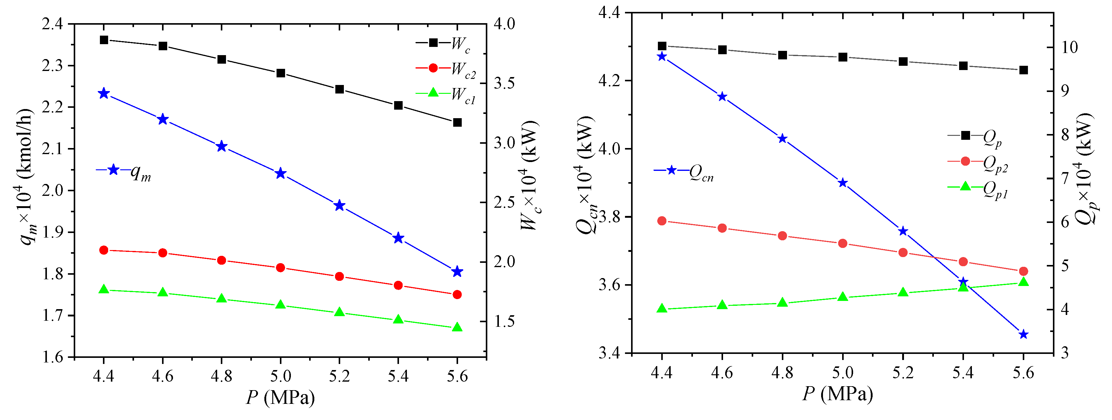
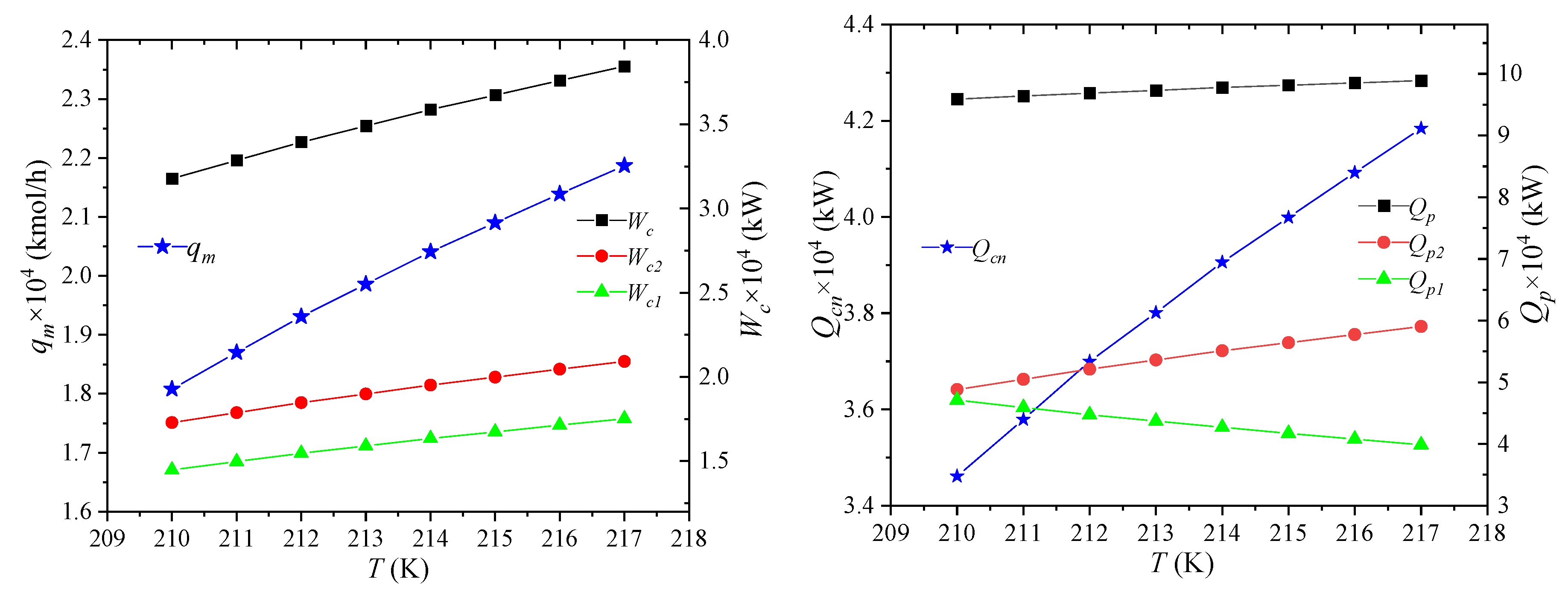
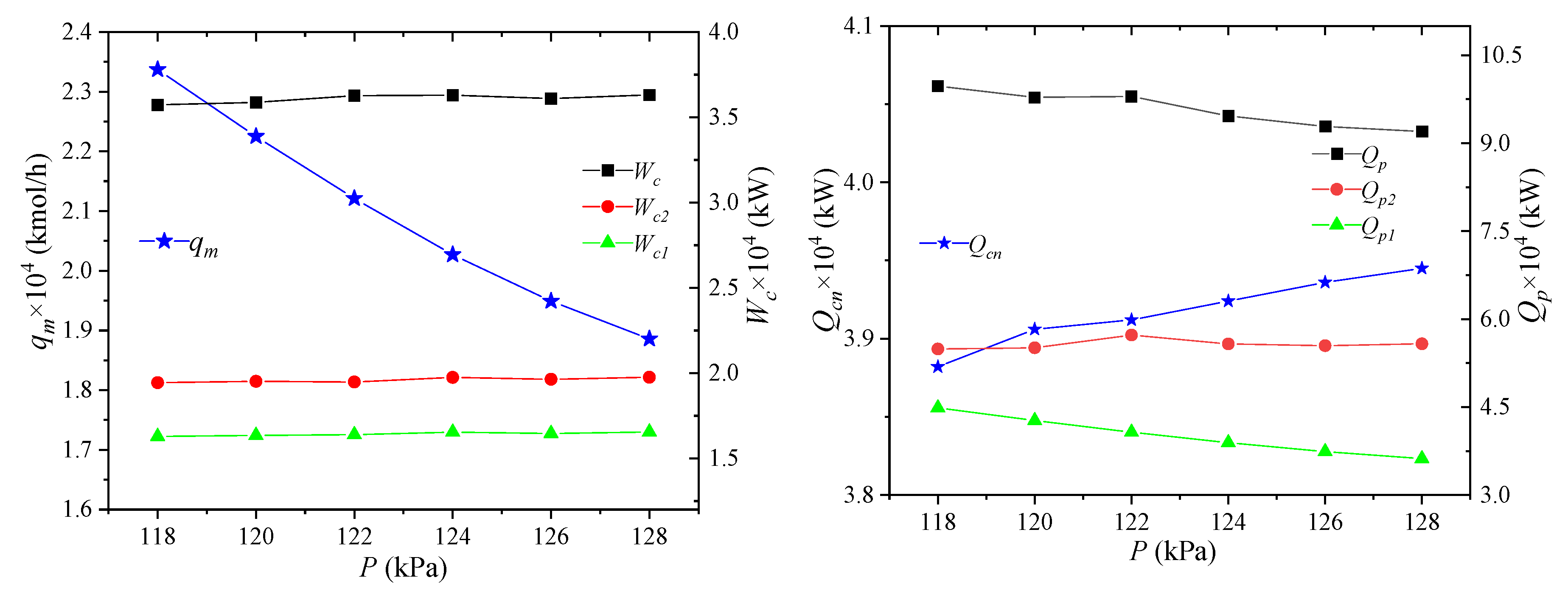
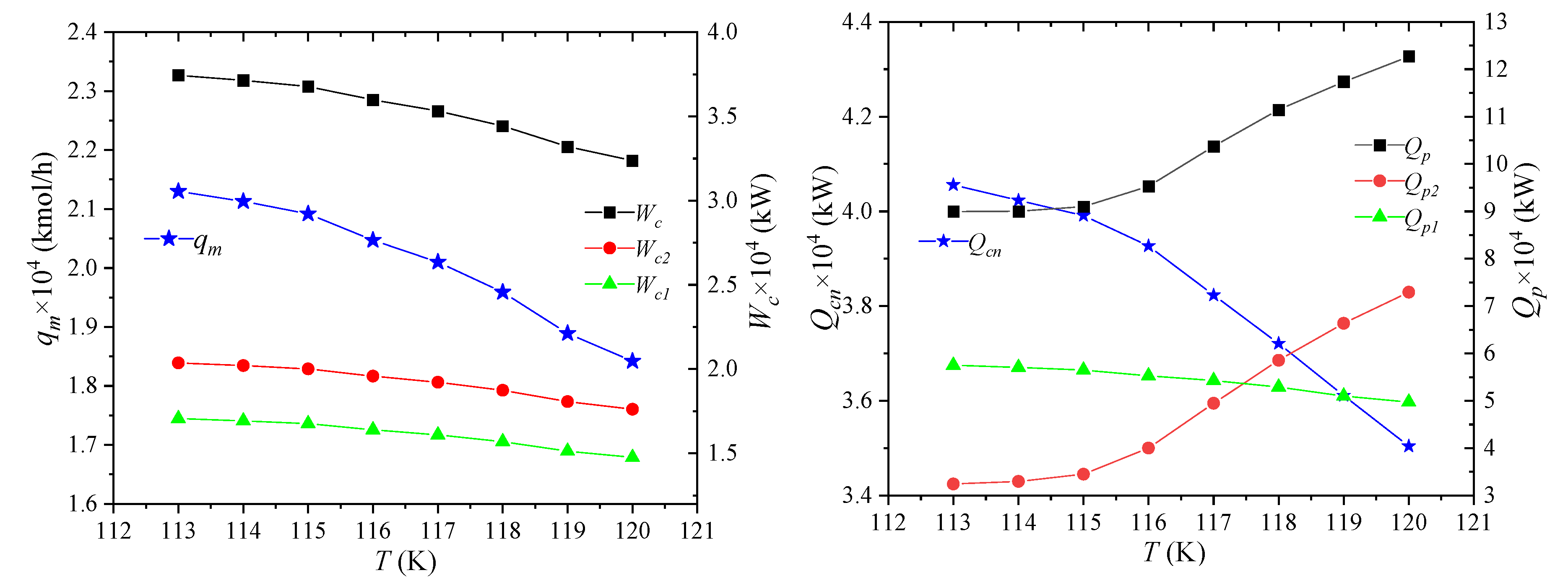
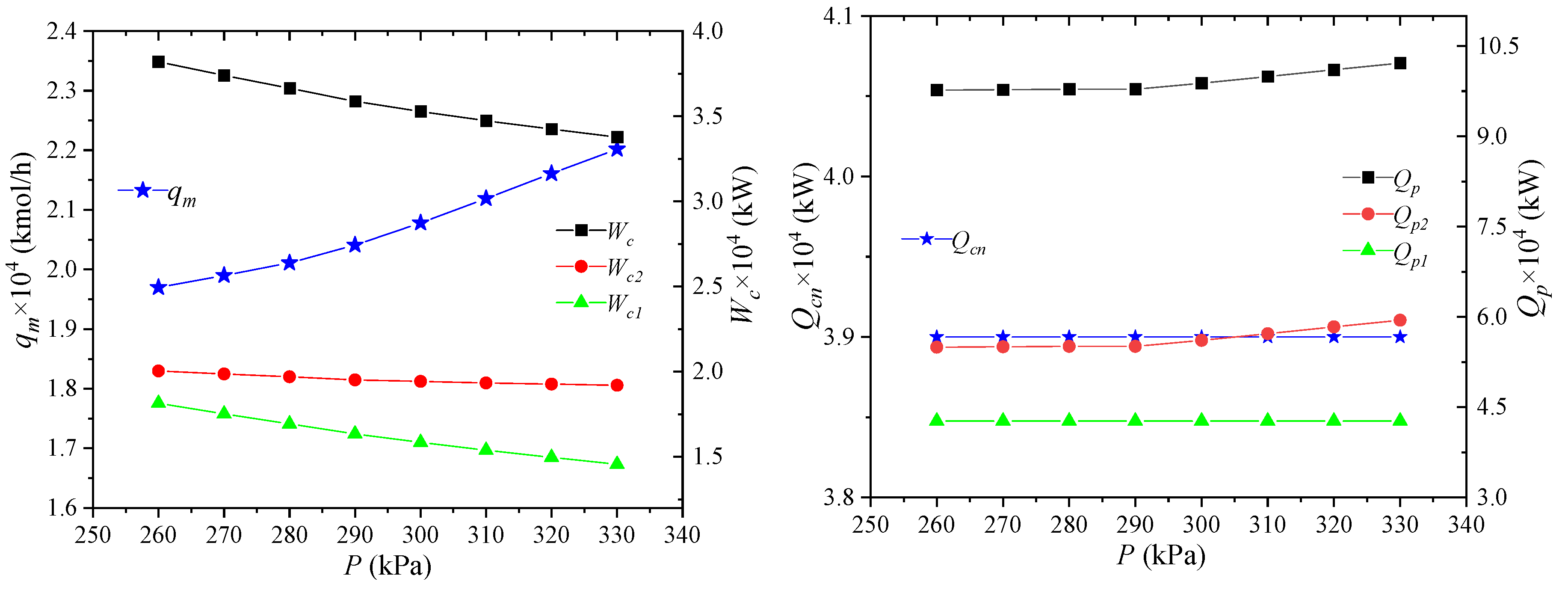
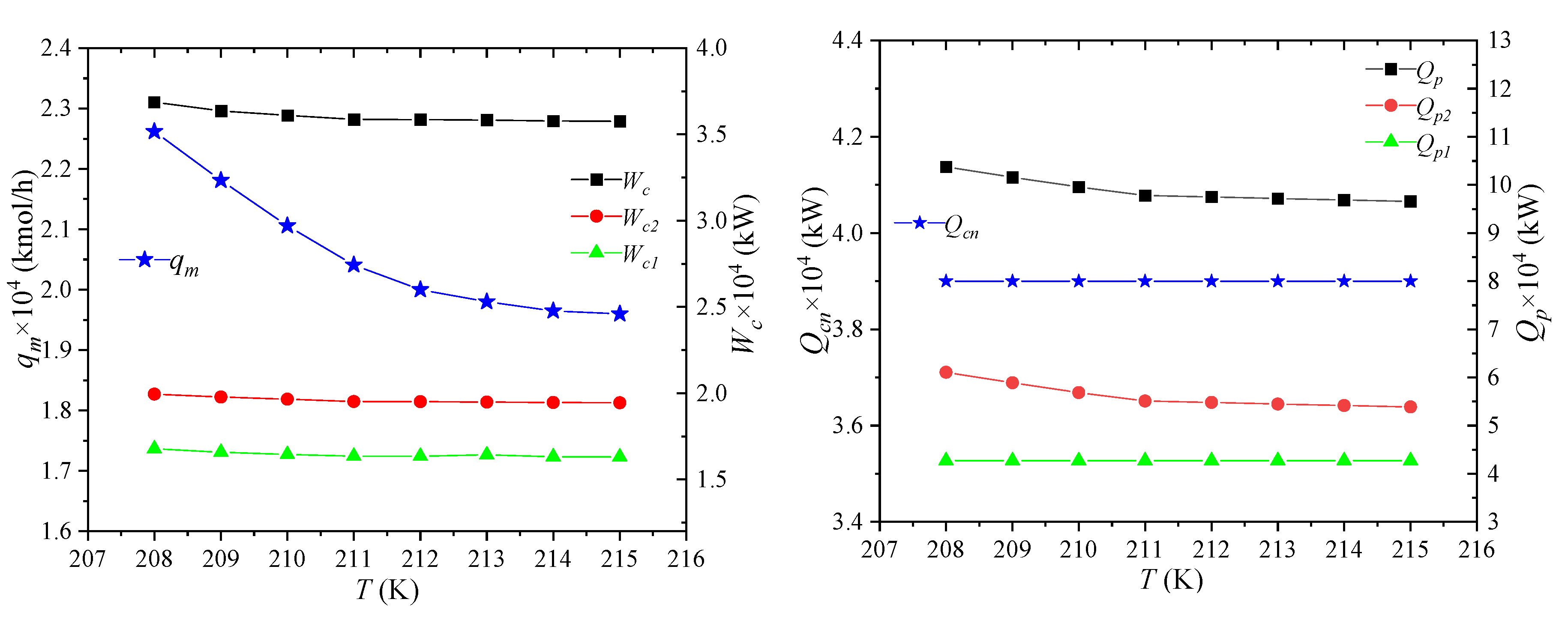
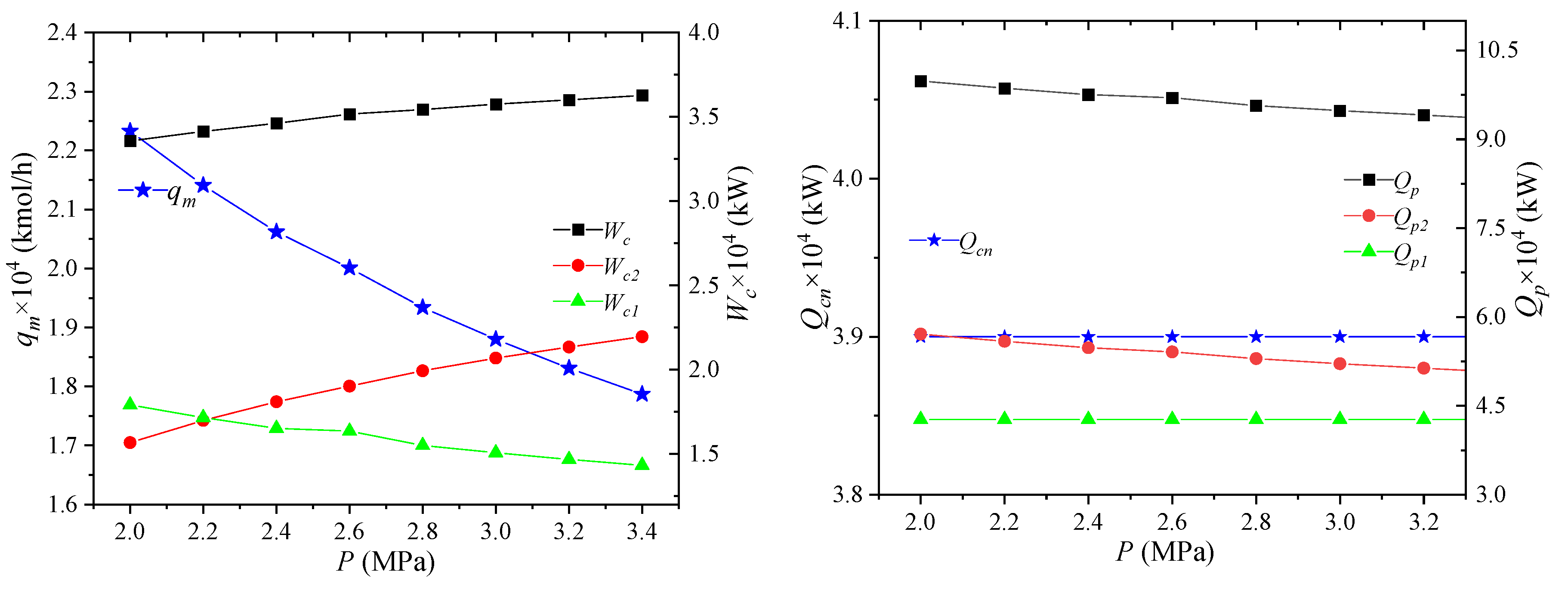
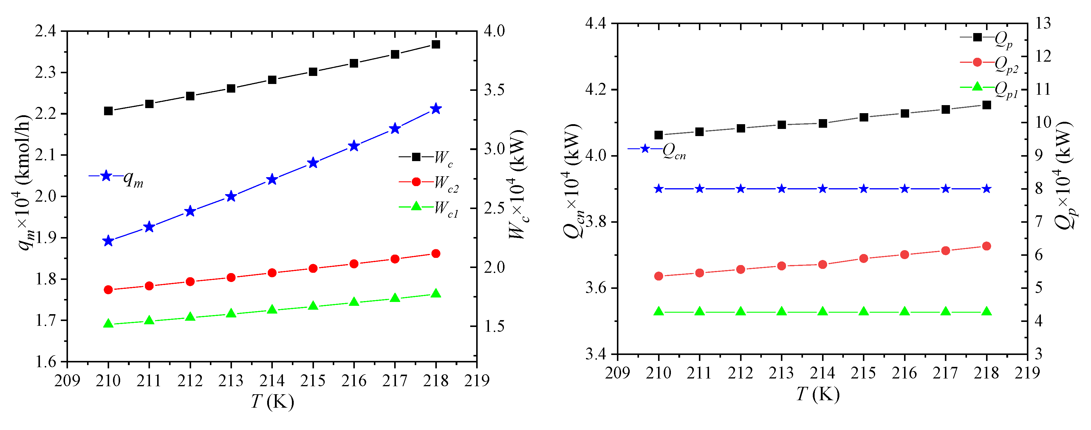
(2) The pressure and temperature of the pre-cooled NG have a greater impact on the flow of the mixed refrigerant, the power consumption of the compressor, the cooling capacity of the NG consumption, and the pre-cooling capacity of the propane. The effect on the pre-cooling capacity of the propane is particularly significant. The temperature and pressure of the low-pressure mixed refrigerant and the temperature and pressure of the high-pressure mixed refrigerant have little effect on the cooling capacity of NG consumption.
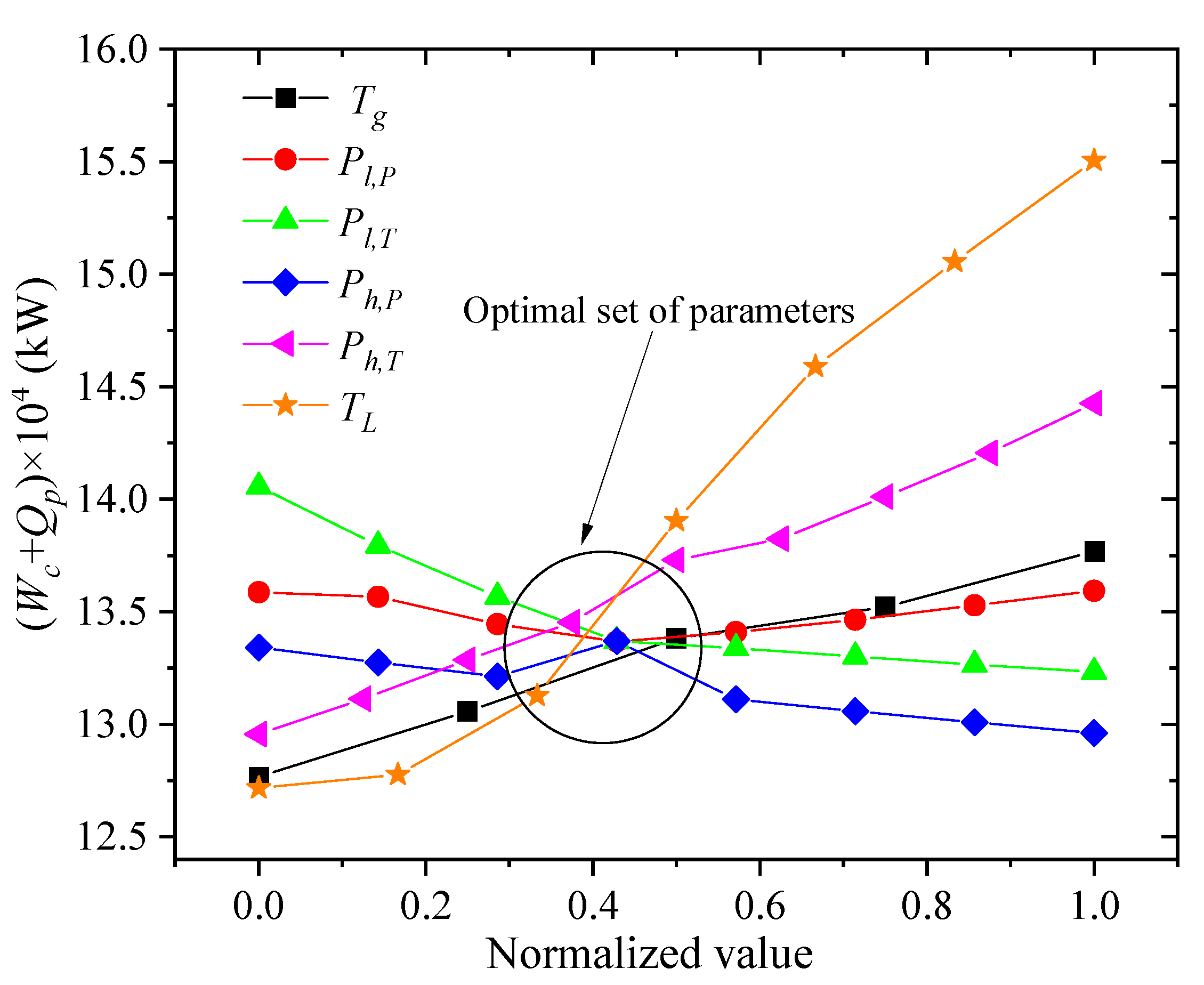
(3) A single variable method is developed on the basis of the parameter sensitivity analysis. Firstly, one selects a certain amount of change on the premise that the objective function is the smallest, and then uses this amount as the amount of other changes to minimize the objective function value. Finally, the parameter set of the optimal process can be found.
(4) The combined analysis of parameter sensitivity and exergy in the present study can not only effectively reduce the power consumption and pre-cooling amount, but also bring down the effective energy loss of each device in the process to a certain extent. The maximum reduction of throttling loss of the process is 60.14%, and the total exergy loss is reduced by 25.8%.

Author Contributions

Z.W. and F.H. conducted the numerical analysis and wrote the paper. Z.W. analyzed the results. Y.J. gave some suggestions and carried out project administration/funding acquisition. W.L. commented on the paper. All authors have read and agreed to the published version of the manuscript.

Funding

This work was funded by the Fundamental Research Funds for the Central Universities (3132020186, 3132019331, 3132019368), the National Natural Science Foundation of China (51906026), Liao Ning Revitalization Talents Program (XLYC1807117), the Pre-reach of General Armament Department (6140922011310). Their support is gratefully acknowledged.

Conflicts of Interest

The authors declare no conflict of interest.

Appendix A

Figure A1. The pseudocode for data interaction connections.
Processes 08 00561 g0a1
Table A1. Calculation results of the process simulation.
ItemP(MPa)T(K)H(KJ) × 108S(KJ/K) × 106qn,v × 104 (kmol)qn,l × 104 (kmol)qn × 104 (kmol)
NG-15298.0−17.63.402.2250.0002.225
NG-25214.0−19.22.781.3210.9042.225
NG-35178.0−20.22.270.0002.2252.225
NG-45165.1−20.42.150.0002.2252.225
NG-55151.4−20.62.030.0002.2252.225
NG-60.12116.4−20.62.120.6001.6252.225
LNG-70.12116.4−16.01.220.0001.6251.625
NG-80.12116.4−4.760.900.6000.0000.600
MR-10.29210.9−16.583.452.0410.0002.041
MR-20.87284.6−15.993.502.0410.0002.041
MR-32.6364.2−15.293.552.0410.0002.041
MR-42.6298.0−16.123.322.0410.0002.041
MR-52.6214.0−17.982.530.9131.1282.041
MR-62.6214.0−6.661.330.9140.0000.914
MR-72.6214.0−1.131.200.0001.1281.128
MR-82.6178.0−7.101.100.5030.4110.914
MR-90.29175.1−6.711.450.9070.0060.914
MR-102.6178.0−1.161.050.0001.1281.128
MR-110.29158.4−1.161.070.2150.9131.128
MR-120.29165.7−18.332.521.1330.9082.041
MR-132.6178.0−3.440.670.5030.0000.503
MR-142.6178.0−3.650.430.0000.4110.411
MR-152.6165.1−3.610.580.2430.2600.503
MR-160.29162.2−3.420.770.5030.0000.503
MR-172.6165.1−3.690.410.0000.4110.411
MR-180.29131.5−3.90.420.1190.2920.411
MR-190.29134.5−7.111.190.6840.2300.914
MR-202.6151.4−3.760.480.0000.5030.503
MR-210.29118.9−3.760.500.1670.3360.503
Table A2. Parameters of each node after optimization.
ItemP(MPa)T(K)H(KJ) × 108S(KJ/K) × 106qn,v × 104 (kmol)qn,l × 104 (kmol)qn × 104 (kmol)
NG-15298.0−13.62.631.7180.0001.718
NG-25212.0−14.82.120.9260.7921.718
NG-35165.3−15.71.660.0001.7181.718
NG-45116.1−16.21.310.0001.7181.718
NG-55114.6−16.21.290.0001.7181.718
NG-60.12114.0−16.21.320.0361.6821.718
LNG-70.12114.0−16.01.270.0001.6821.682
NG-80.12114.0−0.260.050.0360.0000.036
MR-10.263209.0−15.83.291.9430.0001.943
MR-20.78292.8−15.13.381.9430.0001.943
MR-32.7318.5−15.03.241.9430.0001.943
MR-42.7288.0−15.33.131.9430.0001.943
MR-52.7212.0−17.22.370.8001.1431.943
MR-62.7212.0−5.791.150.8000.0000.800
MR-72.7212.0−11.41.220.0001.1431.143
MR-82.7165.3−6.400.820.0460.7540.800
MR-90.263162.3−5.891.240.7730.0270.800
MR-102.7165.3−1.181.020.0001.1431.143
MR-110.263148.7−1.181.030.1820.9611.143
MR-120.263154.9−17.72.280.9760.9661.943
MR-132.7165.3−0.250.060.0460.0000.046
MR-142.7165.3−6.220.760.0000.7540.754
MR-152.7116.1−0.290.040.0000.0460.046
MR-160.263113.1−0.270.050.0250.0210.046
MR-172.7116.1−6.380.600.0000.7540.754
MR-180.263111.7−6.380.600.0410.7120.754
MR-190.263112.0−6.650.650.0660.7340.800
MR-202.7114.6−0.290.040.0000.0460.046
MR-210.26398.8−0.290.040.0090.0370.046

References

  1. Correia de Carvalho, F.; do Nascimento, P.F.; Oliveira de Souza, M.R.; Souza Araujo, A. The Efficiency of Bimodal Silica as a carbon dioxide adsorbent for natural gas treatment. Processes 2020, 8, 289. [Google Scholar] [CrossRef] [Green Version]
  2. Ancona, M.A.; Bianchi, M.; Branchini, L.; Catena, F.; Pascale, A.D.; Melino, F.; Ottaviano, S.; Peretto, A. Overall performance evaluation of small-scale LNG production processes. Appl. Sci. 2020, 10, 785. [Google Scholar] [CrossRef] [Green Version]
  3. Boretti, A. Numerical Analysis of High-Pressure Direct Injection Dual-Fuel Diesel-Liquefied Natural Gas (LNG) Engines. Processes 2020, 8, 261. [Google Scholar] [CrossRef] [Green Version]
  4. Li, J.; Demirel, S.E.; Hasan, M.M. Fuel gas network synthesis using block superstructure. Processes 2018, 6, 23. [Google Scholar] [CrossRef] [Green Version]
  5. Jayakody, H.; Al-Dadah, R.; Mahmoud, S. Cryogenic Energy for Indirect Freeze Desalination—Numerical and Experimental Investigation. Processes 2020, 8, 19. [Google Scholar] [CrossRef] [Green Version]
  6. Kanoğlu, M. Exergy analysis of multistage cascade refrigeration cycle used for natural gas liquefaction. Int. J. Energy Res. 2002, 26, 763–774. [Google Scholar] [CrossRef]
  7. Chang, H.M. A thermodynamic review of cryogenic refrigeration cycles for liquefaction of natural gas. Cryogenics 2015, 72, 127–147. [Google Scholar] [CrossRef]
  8. Gómez, M.R.; Garcia, R.F.; Gómez, J.R.; Carbia Carril, J. Review of thermal cycles exploiting the exergy of liquefied natural gas in the regasification process. Renew. Sust. Energ. Rev. 2014, 38, 781–795. [Google Scholar] [CrossRef]
  9. Qyyum, M.A.; Qadeer, K.; Lee, M. Comprehensive review of the design optimization of natural gas liquefaction processes: Current status and perspectives. Ind. Eng. Chem. Res. 2017, 57, 5819–5844. [Google Scholar] [CrossRef]
  10. Al-Haidous, S.; Al-Ansari, T. Sustainable Liquefied Natural Gas Supply Chain Management: A Review of Quantitative Models. Sustainability 2020, 12, 243. [Google Scholar] [CrossRef] [Green Version]
  11. Eini, S.; Kontogeorgis, G.M.; Rashtchian, D. Cost optimization and flexibility analysis for the liquefaction of an associated natural gas stream. J. Energy Resour. Technol. 2020, 142, 062801. [Google Scholar] [CrossRef] [Green Version]
  12. Khan, M.S.; Karimi, I.A.; Wood, D.A. Retrospective and future perspective of natural gas liquefaction and optimization technologies contributing to efficient LNG supply: A review. J. Nat. Gas. Sci. Eng. 2017, 45, 165–188. [Google Scholar] [CrossRef]
  13. Dauber, F.; Span, R. Modelling liquefied-natural-gas processes using highly accurate property models. Appl. Energy 2012, 97, 822–827. [Google Scholar] [CrossRef]
  14. Al-Sobhi, S.A.; Elkamel, A. Simulation and optimization of natural gas processing and production network consisting of LNG, GTL, and methanol facilities. J. Nat. Gas. Sci. Eng. 2015, 23, 500–508. [Google Scholar] [CrossRef]
  15. Aspelund, A.; Gundersen, T.; Myklebust, J.; Nowak, M.P.; Tomasgard, A. An optimization-simulation model for a simple LNG process. Comput. Chem. Eng. 2010, 34, 1606–1617. [Google Scholar] [CrossRef]
  16. Bittante, A.; Pettersson, F.; Saxén, H. Optimization of a small-scale LNG supply chain. Energy 2018, 148, 79–89. [Google Scholar] [CrossRef]
  17. Alabdulkarem, A.; Mortazavi, A.; Hwang, Y.; Radermacher, R.; Rogers, P. Optimization of propane pre-cooled mixed refrigerant LNG plant. Appl. Therm. Eng. 2011, 31, 1091–1098. [Google Scholar] [CrossRef]
  18. Ghorbani, B.; Mehrpooya, M.; Omid, E. Hybrid solar liquefied natural gas, post combustion carbon dioxide capture and liquefaction. Energy Convers. Manag. 2020, 207, 112512. [Google Scholar] [CrossRef]
  19. Mafi, M.; Amidpour, M.; Naeynian, S.M.M. Comparison of low temperature mixed refrigerant cycles for separation systems. Int. J. Energy Res. 2009, 33, 358–377. [Google Scholar] [CrossRef]
  20. Castillo, L.; Dahouk, M.M.; Scipio, S.D.; Dorao, C.A. Conceptual analysis of the precooling stage for LNG processes. Energy Convers. Manag. 2013, 66, 41–47. [Google Scholar] [CrossRef]
  21. Xu, X.; Liu, J.; Jiang, C.; Cao, L. The correlation between mixed refrigerant composition and ambient conditions in the PRICO LNG process. Appl. Energy 2013, 102, 1127–1136. [Google Scholar] [CrossRef]
  22. Hwang, J.-H.; Roh, M.-I.; Lee, K.-Y. Determination of the optimal operating conditions of the dual mixed refrigerant cycle for the LNG FPSO topside liquefaction process. Comput. Chem. Eng. 2013, 49, 25–36. [Google Scholar] [CrossRef]
  23. Khan, M.S.; Lee, M. Design optimization of single mixed refrigerant natural gas liquefaction process using the particle swarm paradigm with nonlinear constraints. Energy 2013, 49, 146–155. [Google Scholar] [CrossRef]
  24. Shirazi, M.; Mowla, D. Energy optimization for liquefaction process of natural gas in peak shaving plant. Energy 2010, 35, 2878–2885. [Google Scholar] [CrossRef]
  25. Primabudi, E.; Morosuk, T.; Tsatsaronis, G. Multi-objective optimization of propane pre-cooled mixed refrigerant (C3MR) LNG process. Energy 2019, 185, 492–504. [Google Scholar] [CrossRef]
  26. Lee, G.C.; Smith, R.; Zhu, X.X. Optimal synthesis of mixed-refrigerant systems for low-temperature processes. Ind. Eng. Chem. Res. 2002, 41, 5016–5028. [Google Scholar] [CrossRef]
  27. Nogal, F.D.; Kim, J.-K.; Perry, S.; Smith, R. Optimal design of mixed refrigerant cycles. Ind. Eng. Chem. Res. 2008, 47, 8724–8740. [Google Scholar] [CrossRef]
  28. Wang, Z.; Sundén, B.; Li, Y. A novel optimization framework for designing multi-stream compact heat exchangers and associated network. Appl. Therm. Eng. 2017, 116, 110–125. [Google Scholar] [CrossRef]
  29. Wang, Z.; Cai, W.; Han, F.; Ji, Y.; Li, W.; Bengt, S. Feasibility study on a novel heat exchanger network for cryogenic liquid regasification with cooling capacity recovery: Theoretical and experimental assessments. Energy 2019, 181, 771–781. [Google Scholar] [CrossRef]
  30. Vikse, M.; Watson, H.A.J.; Gundersen, T.; Barton, P.I. Simulation of dual mixed refrigerant natural gas liquefaction processes using a nonsmooth framework. Processes 2018, 6, 193. [Google Scholar] [CrossRef] [Green Version]
  31. Gu, J.; Yang, S.; Kokossis, A. Modeling and Analysis of Coal-Based Lurgi Gasification for LNG and Methanol Coproduction Process. Processes 2019, 7, 688. [Google Scholar] [CrossRef] [Green Version]
  32. Sun, X.; Liu, L.; Zhuang, Y.; Zhang, L.; Du, J. Heat exchanger network synthesis integrated with compression-absorption cascade refrigeration system. Processes 2020, 8, 210. [Google Scholar] [CrossRef] [Green Version]
  33. Qyyum, M.A.; Duong, P.L.T.; Lee, S. Dual mixed refrigerant LNG process: Uncertainty quantification and dimensional reduction sensitivity analysis. Appl. Energy 2019, 250, 1446–1456. [Google Scholar] [CrossRef]
  34. Wu, J.; Ju, Y. Design and optimization of natural gas liquefaction process using brazed plate heat exchangers based on the modified single mixed refrigerant process. Energy 2019, 186, 115819. [Google Scholar] [CrossRef]
  35. Zhang, J.; Meerman, H.; Benders, R.; Faaij, A. Technical and economic optimization of expander-based small-scale natural gas liquefaction processes with absorption precooling cycle. Energy 2020, 191, 116592. [Google Scholar] [CrossRef]
  36. Khan NB, N.; Barifcani, A.; Tade, M.; Pareek, V. A case study: Application of energy and exergy analysis for enhancing the process efficiency of a three-stage propane pre-cooling cycle of the cascade LNG process. J. Nat. Gas. Sci. Eng. 2016, 29, 125–133. [Google Scholar] [CrossRef] [Green Version]
  37. Sousa, A.M.; Matos, H.A.; Pereira, M.J. Modelling Paraffin Wax Deposition Using Aspen HYSYS and MATLAB. In Computer Aided Chemical Engineering; Elsevier: Amsterdam, The Netherlands, 2019; Volume 46, pp. 973–978. [Google Scholar]
  38. Gulied, M.; Al Nouss, A.; Khraisheh, M.; Aimomani, F. Modeling and simulation of fertilizer drawn forward osmosis process using Aspen Plus-MATLAB model. Sci. Total Environ. 2020, 700, 134461. [Google Scholar] [CrossRef]
Figure 1. Schematic diagrams of three natural gas (NG) liquefaction processes. (a) Cascade type; (b) expander type; (c) mixed refrigerant type.
Processes 08 00561 g001
Figure 2. Flow chart of NG liquefaction with propane pre-cooled mixed refrigerant.
Processes 08 00561 g002
Figure 3. Flow chart of propane pre-cooling process.
Processes 08 00561 g003
Figure 4. Effects of NG pressure on process performance.
Processes 08 00561 g004
Figure 5. Effects of NG temperature on process performance.
Processes 08 00561 g005
Figure 6. Effects of NG storage pressure on process performance.
Processes 08 00561 g006
Figure 7. Effects of NG storage temperature on process performance.
Processes 08 00561 g007
Figure 8. Effects of low-pressure mixed refrigerant pressure on process performance.
Processes 08 00561 g008
Figure 9. Effects of low-pressure mixed refrigerant temperature on process performance.
Processes 08 00561 g009
Figure 10. Effects of high-pressure mixed refrigerant pressure on process performance.
Processes 08 00561 g010
Figure 11. Effects of high-pressure mixed refrigerant pressure on process performance.
Processes 08 00561 g011
Figure 12. Relationship between the change of each parameter and the objective function.
Processes 08 00561 g012
Table 1. Literature review and gap.
AuthorYearObject and MethodCharacteristic
Dauber et al. [13]2012Modelling liquefied-natural-gas processes used Matlab, Aspen and other software, compared the performance and parameters of several liquefaction processes.Thermodynamic cycle, system and equipment’s simulation, the constant thermophysical property hypothesis.
ASobhi et al. [14]2015
Castillo et al. [22]2013
Mafi et al. [24]2009
Aspelund et al. [15]2010Using intelligent algorithms to optimize the thermodynamic performance with single and multiple objective functions.Determined the optimal condition, compared various process parameters and related performance, global optimization of cycle and device performance.
Bittante et al. [16]2018
Alabdulkarem et al. [17]2011
Khan et al. [20]2013
Primabudi et al. [32]2019
Vikse et al. [29]2018A new mixed refrigerant natural gas liquefaction processes, multicomponent refrigerant analysis, new optimization frameworks and methods.Variable property hypothesis, multi-process optimization.
Gu et al. [30]2019
Qyyum et al. [33]2019
Table 2. Natural gas (NG) liquefaction process initial data.
ItemNGHigh Pressure RefrigerantLow Pressure RefrigerantLNG
Pressure/MPa5.02.60.290.12
Temperature/K216216212116.8
Table 3. Molar composition of NG and mix refrigerant.
ItemN2CH4C2H6C3H8IC4H10NC4H10
NG/%0.782.011.24.01.20.9
Mix refrigerant/%5.051.034.010.00.00.0
Table 4. Exergy loss of each equipment in process.
ItemCompressorHeat ExchangerThrottle ValveMixerTotal
Loss × 104/kW2.0401.1631.1390.0544.396
Ratio/%46.425.925.91.2100
Table 5. Influence of each parameter change on the objective function.
ItemTgPl,PPl,TPh,PPh,TTL
Trend of parameter 1.9%↑11.54%↑3.34%↑70%↑3.81%↑2.5%↑
Trend of objective function4.7%↑1.64%↓6.22%↓2.93%↓11.31%↑21.9%↑
Table 6. Exergy loss of each equipment before and after.
ItemCompressorHeat ExchangerThrottle ValveMixerTotal
Before × 104/kW2.0401.1631.1390.0544.396
After × 104/kW1.9460.8360.4540.0263.262
Ratio4.61%28.11%60.14%51.85%25.80%

