Review

Thermal Biomass Conversion: A Review

by
Witold M. Lewandowski
1,*,
Michał Ryms
1 and
Wojciech Kosakowski
2
1
Faculty of Chemistry, Department of Energy Conversion and Storage, Gdansk University of Technology, G.Narutowicza 11/12, PL-80-233 Gdańsk, Poland
2
Polmos Żyrardów Sp. z o.o. (ul. Mickiewicza 1-3), PL-96-300 Żyrardów, Poland
*
Author to whom correspondence should be addressed.
Processes 2020, 8(5), 516; https://doi.org/10.3390/pr8050516
Submission received: 28 February 2020 / Revised: 21 April 2020 / Accepted: 22 April 2020 / Published: 27 April 2020
(This article belongs to the Special Issue Biomass Processing and Conversion Systems)

Abstract

:
In this paper, the most important methods of thermal conversion of biomass, such as: hydrothermal carbonization (180–250 °C), torrefaction (200–300 °C), slow pyrolysis (carbonization) (300–450 °C), fast pyrolysis (500–800 °C), gasification (800–1000 °C), supercritical steam gasification, high temperature steam gasification (>1000 °C) and combustion, were gathered, compared and ranked according to increasing temperature. A comprehensive model of thermal conversion as a function of temperature, pressure and heating rate of biomass has been provided. For the most important, basic process, which is pyrolysis, five mechanisms of thermal decomposition kinetics of its components (lignin, cellulose, hemicellulose) were presented. The most important apparatuses and implementing devices have been provided for all biomass conversion methods excluding combustion. The process of combustion, which is energy recycling, was omitted in this review of biomass thermal conversion methods for two reasons. Firstly, the range of knowledge on combustion is too extensive and there is not enough space in this study to fully discuss it. Secondly, the authors believe that combustion is not an environmentally-friendly method of waste biomass utilization, and, in the case of valuable biomass, it is downright harmful. Chemical compounds contained in biomass, such as biochar, oils and gases, should be recovered and reused instead of being simply burnt—this way, non-renewable fuel consumption can be reduced.

1. Introduction

Historically, the oldest thermal methods for utilizing biomass were combustion, carbonization and tar production. These were already known in ancient Egypt, Greece and China, where a tomb with the corpse of a woman from 2000 years ago was discovered in which, due to the presence of a large amounts of active charcoal and antiseptic tar, there was no putrefaction and decay, and the corpse was in such a condition that it was possible to determine not only the age of the woman, but also the cause of her death (cardiac arrest). Even melon seeds found in the woman’s stomach did not decay and germinated 20 years later [1]. The antiseptic properties of tar and medicinal charcoal are still exploited today. In the Middle Ages, the development of metal smelting, as well as the production of ceramics and glass increased the demand for charcoal, which persists on a high level to this day (absorbers, fillers, catalysts, pigments and popular barbecue fuel).
The history of solid fuels gasification is much shorter and dates back only about 200 years. Wood gas (ger.: holzgas) was utilized during World War II. Armies trying to become independent of oil used wood gas to fuel automobiles. The gas consisting of CO, H2 and CH4, as well as a certain amount of non-flammable components (N2, CO2 and steam) was produced from wood in gasifiers mounted on the vehicles.
Currently utilized methods of thermal biomass conversion include combustion, gasification, biocarbonisation, torrefaction, dry distillation and pyrolysis. In relation to waste biomass, these processes are sometimes called energy recycling (direct combustion, combustion after gasification), material recycling (gasification, torrefaction, dry distillation and pyrolysis) and chemical recycling (producing biocarbonate, gases (CO, H2, CH4 and other), liquid complex products (tar, turpentine, pyrenes, phenols, etc.) and simple chemical compounds (pyrene, toluene, methanol, limonene, etc.)) [2,3].

2. Theoretical Background

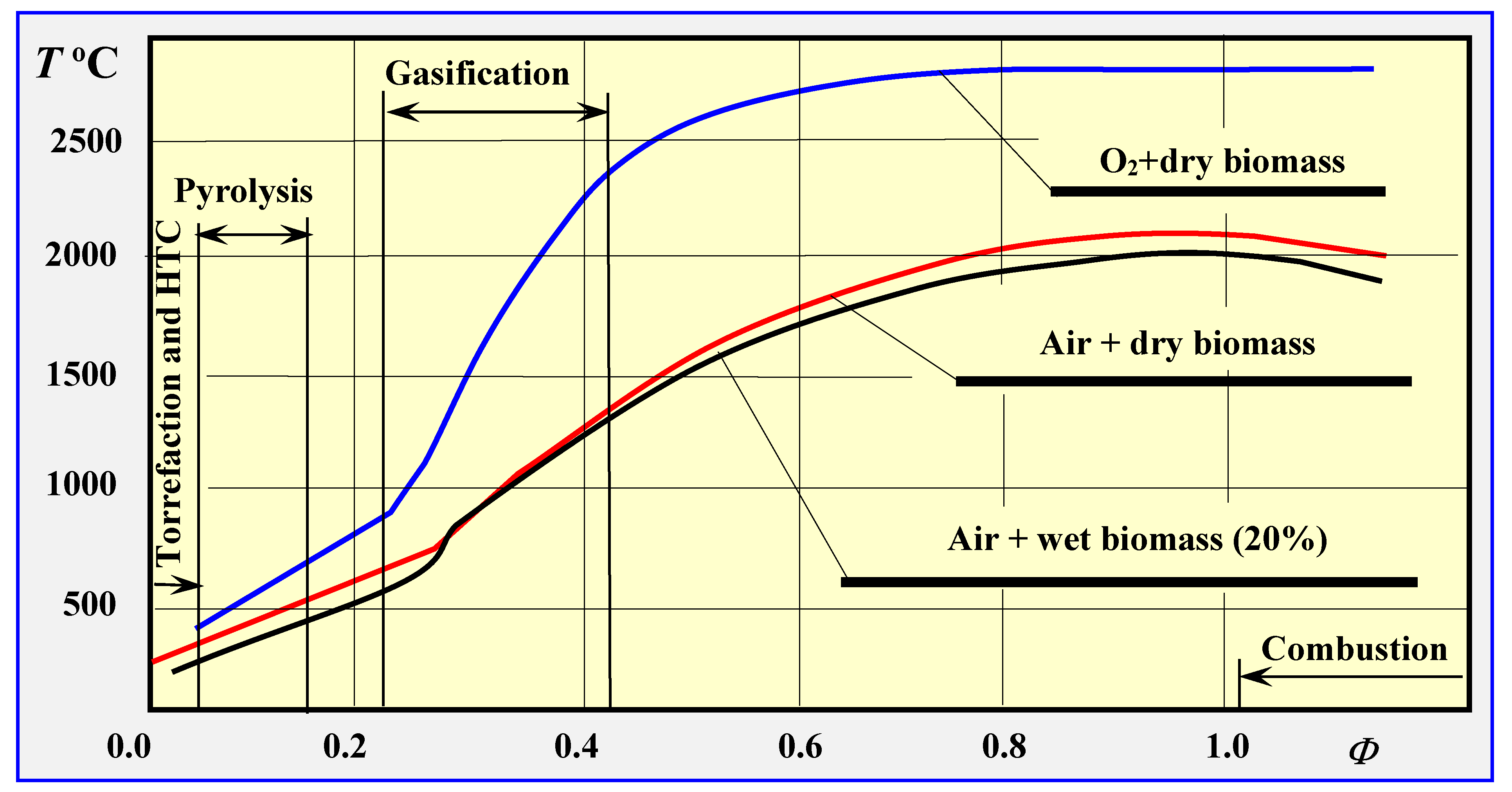
2.1. Methods of Thermal Biomass Conversion

Depending on the temperature and amount of oxygen involved in the thermal decomposition of biomass, the following versions of the process are possible: drying, torrefaction, carbonization, pyrolysis, gasification and combustion, which can be characterized as follows:
Hydrothermal carbonization (HTC) (180–250 °C) + hot pressurized water.
CH1.4O0.6 + H2O → hydrocarbon (solid fuel fulfilling the European standard (EN 14961-6) [4]) + gaseous and liquid residues
Torrefaction: Biomass (200–300 °C) → 30% (gases + volatiles) + 70% torrefied biomass [5]
CH1.4O0.6 → C0.7H1.0O0.4 (solid) + C0.3H0.4O0.2 (gasses)
Slow pyrolysis (carbonization): Biomass + O2 (a small amount at the beginning) (280–550 °C) → biochar
CH1.4O0.6 → C + tar + 0.6 H2O + 0.1 H2 and other gas products
Fast pyrolysis: Biomass (500–800 °C) → biochar + oil + flammable gas
CH1.4O0.6 → about 200 different volatile compounds (oil, tar) + C + CO + H2O + H2 + and other flammable gases
Gasification: Biomass + O2 (limited amount) (800–1000 °C) → flammable gas,
CH1.4O0.6 + 0.2 O2 → CO + 0.7 H2 (theoretically),
CH1.4O0.6 + 0.4 O2 → 0.7 CO + 0.3 CO2 + 0.6 H2 + 0 1 H2O (technically).
Supercritical steam gasification: Biomass + H2O → H2 + CO2,
CH1.4O0.6 + 1.4 H2O → CO2 + 2.1 H2.
High temperature steam gasification: Biomass + H2O (>1000 °C) → CO2 + H2
CmHn + 2m H2O → m CO2 + (2m + n/2) H2
Combustion: Biomass + O2 (stoichiometric amount) → thermal energy + flue gas
CH1.4O0.6 + 1.05 O2 + (3.95 N2) → CO2 + 0.7 H2O + (3.95 N2).
The above division does not include catalytic pyrolysis processes [6,7,8,9,10,11,12,13,14].
Depending on the coefficient of the amount of oxygen consumed in the process of thermal decomposition of biomass ϕ, which is the ratio of the mass of oxygen supplied in the process to the amount of biomass, the process varies from pyrolysis, through gasification, to complete combustion of biomass [15]. Complete combustion of biomass occurs for stoichiometric amounts of oxygen or air, which correspond to the coefficients: ϕc = 1.476, for pure oxygen and ϕc = 6.36 for air [16].
Figure 1 presents the impact of the relative coefficient of the amount of air consumed, which is the ratio of the actual coefficient of the amount of oxygen consumed to the value of this coefficient at total combustion Φ = ϕ/ϕc, on the course of thermal decomposition of biomass at atmospheric pressure (p = 1 atm.) [16,17].
From an ecological standpoint, the least favorable process is the combustion of biomass, and therefore only devalued waste biomass originating, e.g., from municipal waste (RDF—Refuse-Derived Fuel) or from sewage treatment plants (screenings, activated sludge) should be utilized using this method. All other types of biomass, both full-valued and waste, should be subjected to initial thermal conversion (torrefaction, pyrolysis or gasification) before final combustion. As a result of this material or chemical recycling, many valuable products, semi-products and chemical compounds are recovered, otherwise obtained through industrial syntheses, which are time- and work-consuming, more expensive and negatively impact the environment [15].
Therefore, in this discussion and review of methods of thermal biomass conversion, energy recycling through combustion has been omitted. The presentation of this type of biomass conversion, also interesting from both thermodynamic and technical standpoints, requires a separate study.

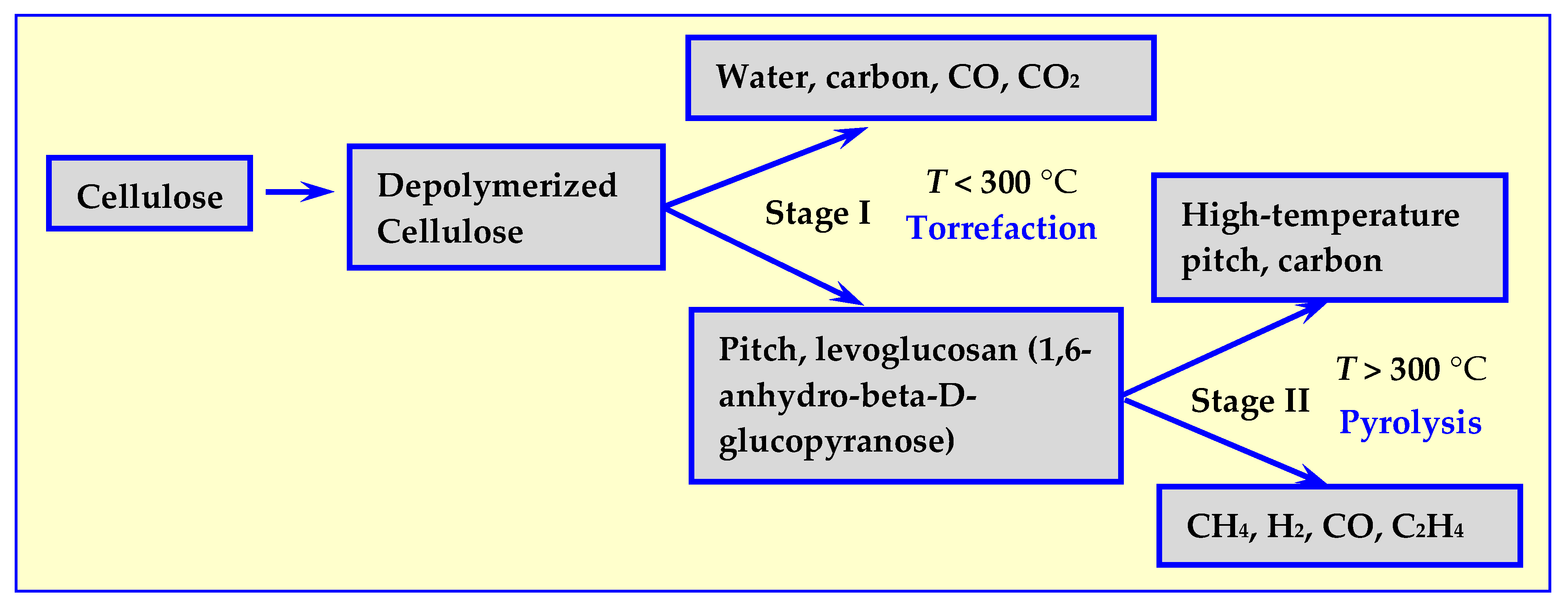
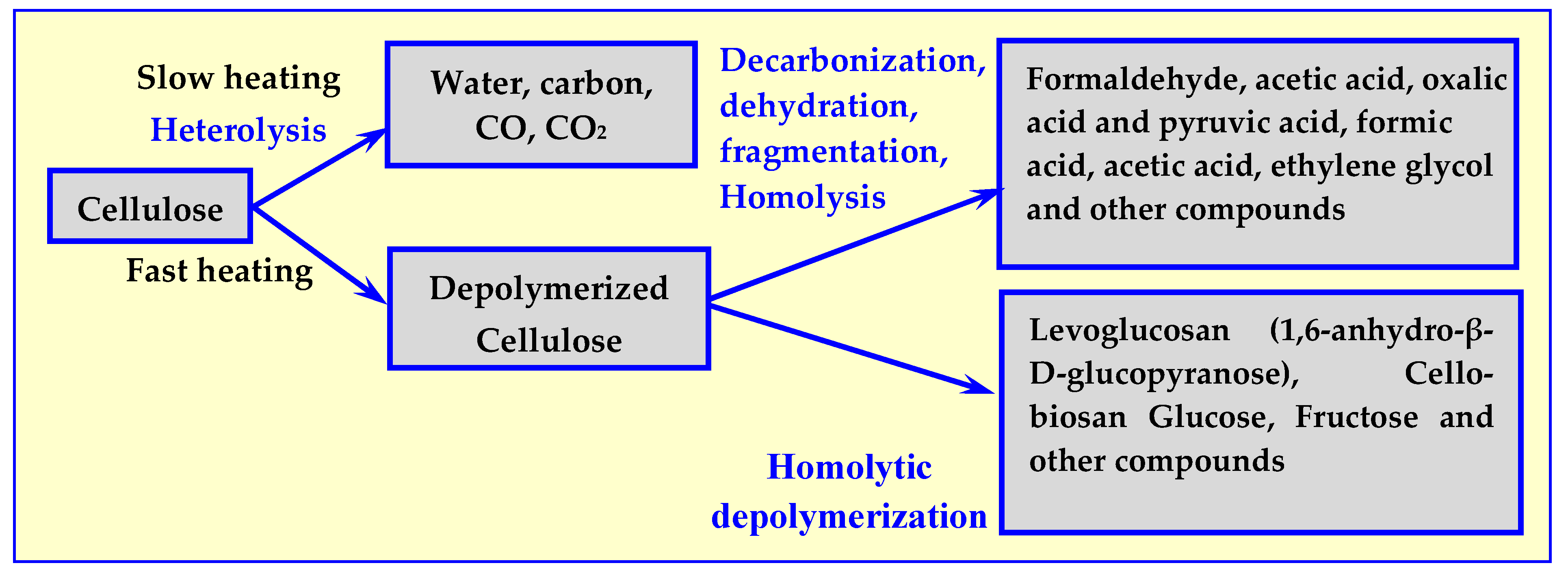
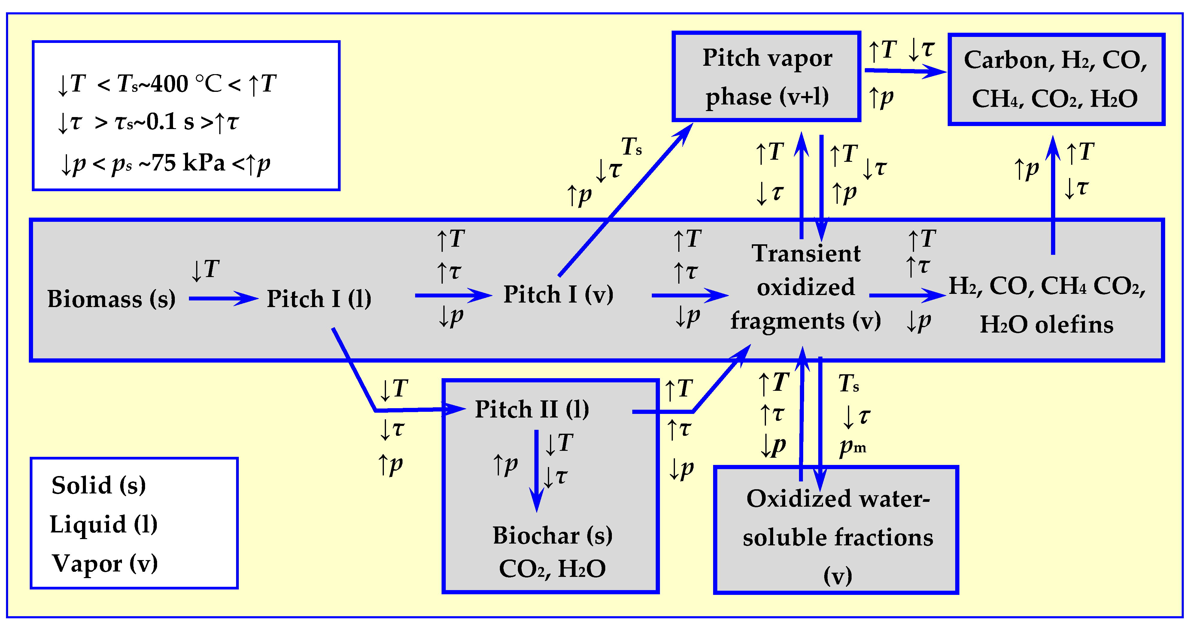
2.2. Mechanisms of Dry Thermal Decomposition of Biomass

Cellulose is the main component of biomass for energy utilization. Initially, it was believed that its thermal decomposition depends only on the temperature [18,19,20,21] and, as shown in Figure 2, proceeds in two stages: initial decomposition at temperatures below 300 °C, and further degradation and depolymerization at temperatures above 300 °C [17].
In Stage I, cellulose can decompose according to two competing mechanisms: into biochar (in case of decomposition of wood into charcoal), CO2 and H2O or into tar consisting of cellulose fragments and monomers, mainly levoglucosan, as shown in Figure 2. As temperature increases, in Stage II, further decomposition occurs, resulting in liquid (high temperature pitch) or gaseous products.
Subsequent studies [22] have shown that not only the value of temperature but also the rate of its increase have an impact on the course of thermal decomposition, as well as the composition of the process’ products. The results of these tests are presented in Figure 3.
A complete picture of thermal decomposition of biomass was obtained after considering the decomposition mechanisms—not only of cellulose [23], but also of other biomass components: hemicellulose [24,25,26,27] and lignin [26,27,28,29], as well as the impact of pressure on the process. The first holistic thermal biomass decomposition model, taking temperature, rate of decomposition and pressure into consideration, was developed as a result of the consensus of a specialist work group assembled at the Quick Pyrolysis meeting [30]. The comprehensive model proposed has been schematically presented in Figure 4. The impact of considered parameters: temperature T, heating rate τ and pressure p on the directions of thermal biomass decomposition is marked with arrow directions, which determine either increase or decrease in the value of these parameters in relation to reference values of Ts, τs and ps.

3. Torrefaction

Due to large volume and low weight, proper transport of biomass across longer distances is unprofitable. Therefore, energy plantations and other biomass sources must be located within a radius of up to 100 km from the energy processing plant. If, however, this is not possible, biochar, which has a much higher concentration of energy can be delivered to heating or cogeneration plants instead of biomass [31,32,33,34,35,36]. The density of biochar is not as high as the density of coal, but the range of its profitable transport to heat and power plants is within a few hundred kilometers. In addition, biochar can be burned in typical coal-fired boilers, in contrast to biomass, which requires special boilers. It can also be co-combusted with coal in coal-fired boilers, but the share of biochar cannot exceed approx. 15%.
Aside from the possibility of co-firing biochar in any solid fuel boiler without the need for alteration and modernization, another advantage of this fuel is its eco-friendliness resulting from a lack of sulfur, the possibility of using ash in agriculture and the fact that, unlike coal, oil or natural gas, biochar is a renewable energy source [37].
As an effect of torrefaction performed in inert atmosphere at 200–300 °C, the same physical and chemical properties of raw biomass change as follows: its moisture decreases, energy density and heating values increase, O/C and H/C ratios decrease, it becomes hydrophobic, its grindability becomes better and its properties change from heterogeneous to more homogeneous [38,39]. Different names for torrefaction include: biomass carbonization, roasting, slow- and mild pyrolysis, wood cooking and high-temperature drying [34]. Its mechanism based on hemicellulose, lignin and cellulose thermal degradation has been clearly explained in [40,41,42,43,44].

3.1. Biochar

Similar to charcoal, biochar (also known as biocarbon, biocarbonate or BIOcarbon®) is obtained during the slow heating of biomass in absence of air. This process is currently carried out in closed batch heating reactors working either in periodic or continuous mode. The course of biomass biocarbonization reaction with the general formula (CH2O)n is as follows:
(CH2O)n → C + H2O + tar + volatiles + gases
Biochar has a much higher calorific value compared to dry biomass from which it was created, due to it no longer containing water physically and chemically related to biomass. For example, biocarbon from pine chips with a heating value of 19.6 MJ/kg has a heating value of 27.9 MJ/kg, from alder shavings (18 MJ/kg)–26.7 MJ/kg, from furniture waste (17 MJ/kg)–26 MJ/kg, from chipboard (17.2 MJ/kg)–25.4 MJ/kg and from fine sawdust (16.3 MJ/kg)–26.6 MJ/kg [45,46].

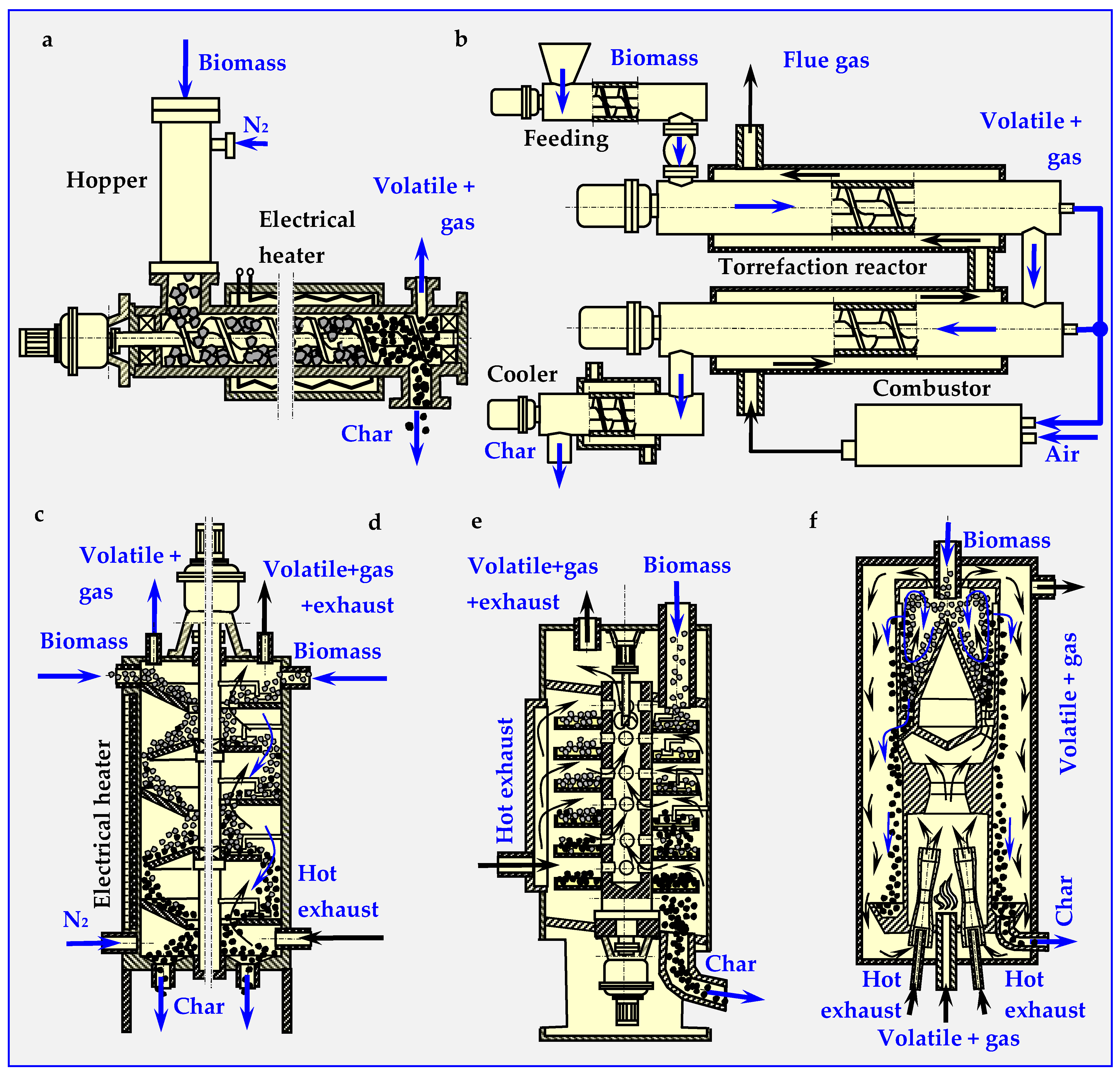
3.2. Torrefaction Reactors and Technologies

The reactors for biomass slow (carbonization) and fast biomass pyrolysis are very similar [39], and sometimes even identical. As all devices for anaerobic, thermal conversion of biomass, these reactors must be hermetic to avoid any uncontrolled supply of air, which may burn the biochar, destroy the installation and even cause a fire. Depending on the heating method, both torrefaction and pyrolysis reactions can be divided into two types: with direct and indirect modes. In the first mode, the energy is transferred by heating media (flue gasses, heat transfer material (HTM) etc.) in direct contact with the feedstock. In the second, indirect mode heating application separates the heating media from the biomass by a conductive barrier such as metal walls [39,47]. Biomass can also be heated by microwaves at a frequency of 2.4 GHz. This frequency forces molecules of biomass to oscillate at the resonant frequency and induces friction and heating [48].
From a technological standpoint, torrefaction reactors are divided into reactors operating periodically and continuously [49]. Because periodical reactors only have historical or research (laboratory) significance [50], one should focus on continuous industrial reactors, such as auger, rotary drum, multistage, multiple hearth furnace (MHF), microwave [11] and others.
Torrefaction reactors can also be classified depending on how the batch is forced to move inside them, i.e., mechanically (auger, rotary, ablative), gravitationally (multiple hearth furnace, turbo-dryer, moving compact bed) and pneumatically (torbed, fluidized bed). Descriptions and diagrams of some of these reactors are presented below.

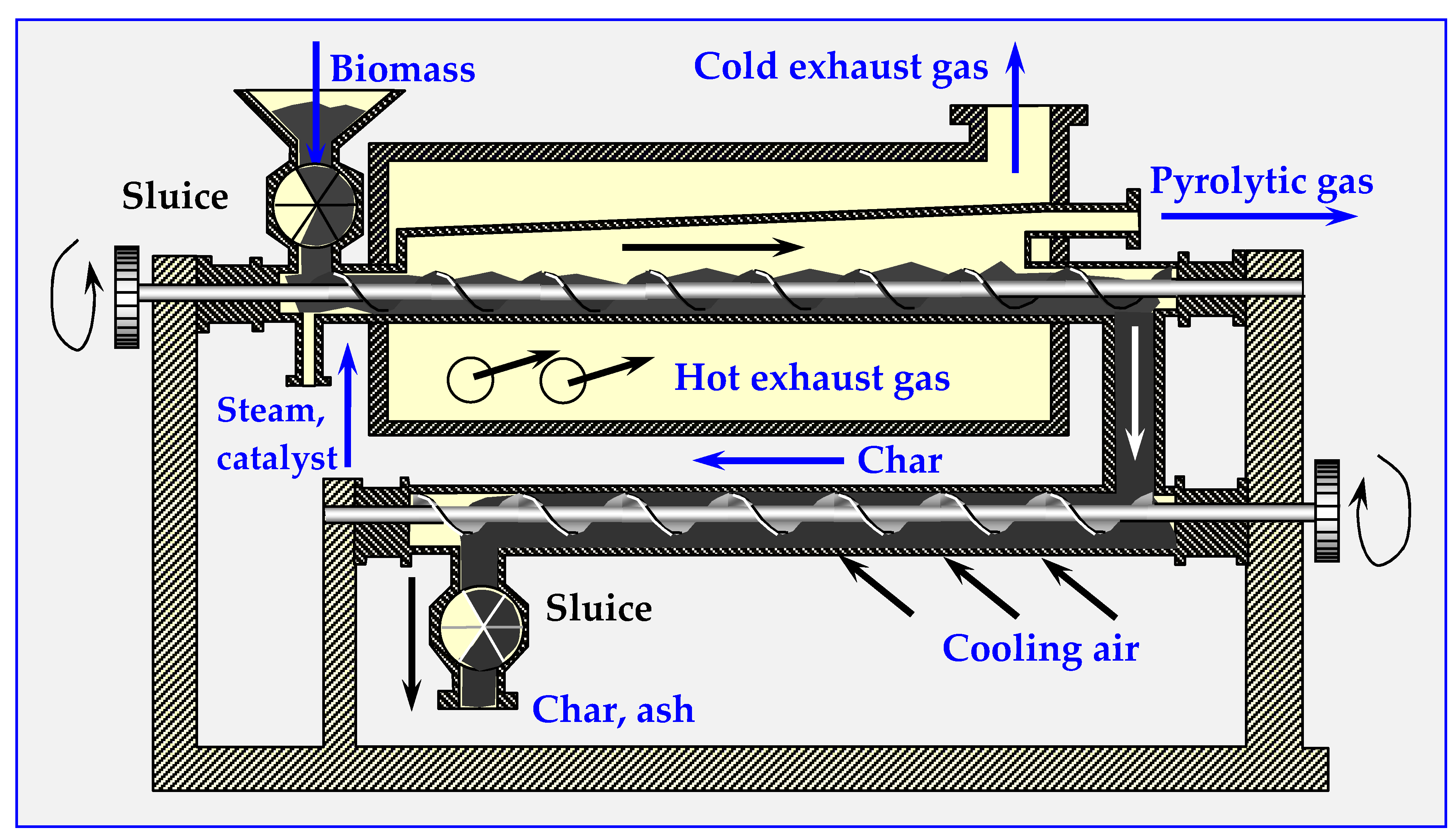
3.2.1. Auger Reactor

The first commercial torrefaction installation operating continuously, employed in the Pechiny process in 1980s (France), included an auger reactor [48]. This reactor consist of one or more helix screws (augers) attached to the shaft rotating in the center of a cylinder [51] (Figure 5a,b). The feedstock moved within the cylinder by the auger mechanism is mixed and, in this case, indirectly heated by cylinder walls. The cylinder containing the feedstock is wrapped in a co-centered, fixed electrical heater with spherical thermal insulation, or a separate pipe (of larger diameter) with hot flue gas medium flowing inside. Gasses generated by the reaction are separated from the solid stream at the end of the screw reactor.
A pilot scale plant (200 kg/h) described in the paper [52] included a pre-heater rotary drum (t = 220 °C) and an auger screw reactor for continuous process of torrefaction performed in N2 atmosphere at t = 308 ± 2 °C. Residence time of 9 min yielded 82% efficiency for willow and 80% efficiency for forest residues [53]. The same auger reactor used for torrefaction of biomass, but for a feed rate of 60 kg/h, temperature t = 265 °C, and retention time of 30 min is described in [54]. The auger reactors studied in the paper [39] have screws with mixing paddles and cut flighting, which intensify mixing and heat transfer.

3.2.2. Rotary Drum Reactor

A rotary drum reactor is adapted for torrefaction from drying technology. It is a long, rotating hollow cylinder placed horizontally with a slight angle of inclination for feedstock flow [51] (presented in detail later in Chapter 4.6—Figure 16b). The rotation of cylinder mixes the material inside and enables intensive heat transfer directly from inert gas or indirectly from the reactor wall. The directly heated reactor utilizes super-heated steam or hot flue gasses from a combustion chamber to create a hot environment of torrefaction. Indirect heating utilizes burners or electric heaters that heat the outer cylinder walls. The reactor with a length of 1.7 m and a diameter of 0.27 m, electrically heated by five external spherical heaters, was used in a pilot plant with a max. production output of 20 kg/h [55].

3.2.3. Multiple Hearth Furnace (MHF)

The MHF is constructed from round, multi-leveled platforms with internal heating mechanism, steam injectors or gas burners. The torrefacted biomass is supplied from the top of the furnace and gravitationally falls from the round stationary shelf to the rotating shelfs through holes in the center of the stationary shelf [51]. In the first variant (electrically heated reactor with conical shelfs), the angle at the base of the shelves is equal to or greater than the bulk angle of the crushed biomass (Figure 5c). This enables automatic gravitational biomass movement from shelf to shelf. In the second version (reactor heated by exhaust gases), biomass movement is caused by scraper blades alternately attached to the rotating shaft and the cylindrical wall of the reactor. Rotary blades scrape the biomass from the stationary shelves towards the center, where the load falls onto the rotary shelf through the central holes. Subsequently, fixed shovels scrape the biomass from the rotary shelves onto the stationary shelf (Figure 5d).
The authors in [56] described a reactor with gravitational movement of the charge (Standard TURBO-DRYER® [57]). In this column, toroid round shelves are attached to a rotary hollow shaft. Flue and gas torrefaction products are sucked in through the holes above the shelves and are transported upwards through the channel in the middle of the shaft to the outside of the reactor (Figure 5e). The biomass supplied from above is directed by scrapers attached to the walls of the reactor into radial holes in the shelf, through which the charge falls down onto a lower shelf. This operating principle can be duplicated as many times as needed to achieve a certain processing level. Independent heating of each shelfs enables better continuous process temperature control so that after drying taking place in the upper part of the reactor, torrefaction can occur in the lower part. In another paper [58], two reactors were used: a laboratory scale isothermal rotary reactor and a pilot-scale multistage tape reactor (outputs: 10 kg/h and 100–500 kg/h, respectively). In the laboratory reactor, torrefaction was conducted at three temperatures: 25, 275 and 300 °C. For each process, the residence time in the inert atmosphere was 40 min, flow rate was 1500 dm3/h and 1 kg biomass batches were introduced.

3.2.4. Torbed Reactor Technology

In a continuous torbed reactor working on a very small, demonstrative scale (reactor diameter of 5 to 7 m, 2 kg/h), a heat-carrying medium is blown from the bottom of the bed with high velocity (50–80 m/s). The medium flows through the heated venturi nozzles, sucking in biomass particles fed into the reactor from above (Figure 5f). Toroidal swirls of biomass particles very rapidly heat the particles on the outer walls of the reactor. This intense heat transfer enables torrefaction at elevated temperatures (up to 380 °C) with short residence times (around 80 s), higher loss of volatiles and relatively small reactor sizes. Recently, a full-scale demonstration plant with a production output of 60,000 t/a was put into operation in Duiven (The Netherlands). The utilized biomass mainly consists of forestry residues. In this installation, multiple stacked Torbed reactors are placed in a series enabling maximum flexibility in fuel characteristics and residence time. [51].

3.2.5. Reactor with Moving Bed

This continuous vertical reactor consists of an enclosed cylindrical vessel where biomass enters from the top, and gradually moves down. A heat-carrying gaseous medium entering from the bottom flows in countercurrent to the top and carries out the torrefaction process at approx. 300 °C at a residence time of 30–40 min. At the bottom of the reactor, the torrefied product leaves the vessel and is cooled down, while at the top of the reactor, volatiles products are removed [51].
In the case of heterogeneous dimensions of biomass particles, the medium will not heat the whole charge at the same rate and will flow unevenly through vertical channels, leading to a non-uniform product at the bottom of the reactor. Though this effect has not yet been observed at a 100 kg/h test reactor [51], its potential occurrence cannot be excluded at reactors with larger capacities.
Fluidized bed reactors [60,61,62], in which local overheating and heterogeneity in the composition of torrefaction products do not occur, are free of this disadvantage.
Some of the reactors for continuous torrefaction of biomass discussed above are schematically shown in Figure 5.

4. Pyrolysis

Pyrolytic thermal decomposition of biomass is a complex process in which the following reactions overlap: dehydration, isomerization, dehydrogenation, aromatization, charring, oxidation and others. These are accompanied by secondary reactions, e.g., thermal decomposition of water into water gas, cracking, syngas synthesis, condensation reactions etc. Depending on the technological parameters—mainly temperature and growth rate—the products of the reactions include steam, carbon oxides, aliphatic and aromatic hydrocarbons, pitch (tar), polymers, hydrogen and coal [63]. The chemical mechanisms of biomass pyrolysis are quite complex. Describing these mechanisms requires introducing detailed definitions and a rather thorough delve into the issues, which, due to the already extensive form of this study, has been omitted, limiting the information in this chapter to the kinetics and technical issues only. Detailed data on the chemical mechanisms of pyrolysis can be found in papers [64,65,66,67,68].

4.1. Slow Pyrolysis—Carbonization

In the first step of wood carbonization, the kiln charge is drying at 100 °C or below to zero moisture content. Further increase in temperature to 280 °C causes thermal degradation, while complex carbonaceous substances are broken down into elemental carbon and chemical compounds, which may also contain some carbon in their chemical structure. The final products are: charcoal, acetic acid, methanol and more complex chemicals, mainly in the form of tars, as well as non-condensable gas consisting mainly of H2, CO and CO2. Small and controlled amount of air introduced into the carbonizing kiln or pit, causing some wood burning, supports the carbonization process [69].

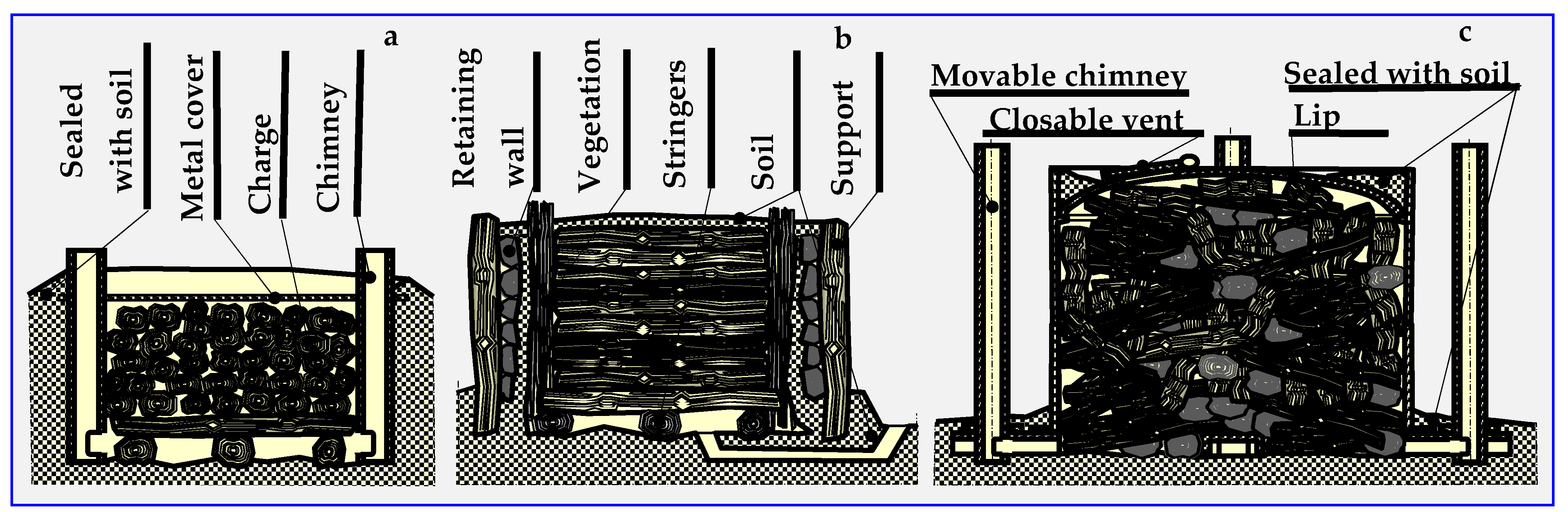
4.2. Historical Outline of Carbonisation and Pyrolysis

The name of thermal decomposition—pyrolysis—comes from the Greek words: fire (pyros) and solution (lysis). The history of pyrolysis is as old as the production of charcoal, tar and pitch. The former, obtained in kilns or retorts since the Middle Ages, was mainly used for smelting metals and, to a small extent, in folk medicine. Many charcoal kiln types are known—pit, mound, brick, Argentine, Brazilian, Missouri, TPI (Tropical Products Institute), Casamance, mixed and Bieszczad retort [70,71]. Figure 6 shows examples of kilns still in use.
Tar and pitch, whose production in tarred plants was a closely guarded secret, were one of the most important export products of Poland until the 19th century. Tar was used to impregnate wood, fabric and leather, seal boats, barrels and vessels, and to mount arrowheads. Due to its antiseptic properties, tar was an irreplaceable agent for treating human and animal skin diseases and for protecting hooves of domestic animals against inflammation and rot. It is used in veterinary and horse farms to this day.
However, the industrial (1770–1830), scientific and technical revolutions (1940s) had a great impact on the development of pyrolysis. The former led to the industrial replacement of wood with coal—a resource that proved to be an irreplaceable raw material for the pyrolytic production of many chemical compounds. This initiated the scientific and technical revolution, in which the development of industrial chemistry had the greatest impact.
The discoveries made at that time by people such as Hans Tropsch echo in current successes of pharmacy, plastic production, textile production, household chemistry development, materials containing PCM in construction and many other branches of industry [72]. It is because of these revolutions that Germany, a country with considerable hard coal resources and non-existent oil reserves, became a giant in the field of chemical coal processing, in which pyrolysis is the most important link. Unfortunately, the development of a technology for producing synthetic liquid fuels from coal also encouraged Germany to start World War II [15].
The development of coke and municipal gas industries also had a great impact on the development of coal pyrolysis. Coke was and still is an irreplaceable raw material in metallurgy, which is the energy and material driving force of industrial revolutions. Urban gas, on the other hand, made it possible to ensure social and living conditions for the inhabitants of the newly created and developing cities, who in turn constituted the workforce of these revolutions.
We are currently seeing renewed interest in biomass pyrolysis, among others, as a source of thermal and electrical energy in energy production, as well as a source of biofuels in automotive industry and transport.

4.3. Biomass Pyrolysis Kinetics

Several semi-global mechanisms compete in the description of biomass lignocellulosic pyrolysis. Three basic models can be distinguished: (I) a process described with a single reaction, which does not allow feedback of the decomposition products on the course of the reaction, but assumes a constant ratio of volatile fraction to biochar, (II) a process described with several reactions in which an appropriate reaction selection allows establishing a detailed correlation between experimental data, (III) a semi-global approach, which takes into consideration the kinetics of mechanisms of both primary and secondary reactions, as well as their feedback on the ratios of three basic pyrolysis products: biochar, liquid and gas fraction.
The first model already enabled designing the first pyrolyzers and the optimization of their prototypes on an engineering level, but only if there was no need to modify and control the composition of end products (gasifiers, biocarbonizers). In case of designing pyrolyzers for converting biomass into liquid fuels, model III was more useful, although at the same time less user-friendly until its numerical version was developed [73].
Based on model III, the ACM (Aspen Custom Modeler) simulation program was also developed, which is a tool enabling the modeling of pyrolysis processes and other complex phenomena [74]. Two mechanisms were considered independently in this modeling:
-
The first—parallel degassing and drying, which assumes that the total volatile output equals the content of the dominant component determined analytically. The accuracy of this division model depends on parameters that are determined experimentally or are derived from literature data [75].
-
The second mechanism consists of the processes of several parallel gasification reactions of j—components [76,77], the kinetics of which are determined by the relationship:
d m c a l c . d t = j = 1 M c j d α j d t ,
where m—the initial mass of the sample, M—ingredient number, and c—weight loss of the j component.
Each of the partial reactions can be approximated by the Arrhenius equation:
d α j d t = A j 1 e E j R T ( 1 α j ) n ,
where A—coefficient, E—energy of activation, α—conversion coefficient, and n—reaction order.
This method of pyrolysis modeling can be applied to any biomass, willow, wood, RDF, sewage sludge, tires and other combustible raw materials. Dynamic simulation calculations carried out in the ACM spreadsheet showed good qualitative compliance with literature data [78]. However, the greatest difficulty in using the last two equations with such a complex process as pyrolysis stems from the unknown values of kinetic coefficients for individual reactions, which show high variability and are sometimes contradictory. Although these coefficients can be approximated for higher temperatures from the results of experimental thermogravimetric tests on pure cellulose conducted at a lower temperature, it is still only an approximation [79]. Controlled pyrolysis of small biomass samples has proved to be a better solution. For example, experimental studies of thermally decomposed pure cellulose samples showed that the decomposition reaction is of the first order and the activation energy is Ecel. = 238 kJ/(g·mol). For a large mass, when the biomass losses are small in relation to the stream of volatile components formed, it will be a pseudo first order reaction. Literature reports indicate that other biomass components are determined this way.
Examples of coefficients A and activation energies for known pyrolysis mechanisms are presented below [80].

4.3.1. Pyrolysis Kinetics according to the Broido Mechanism

The Broido mechanism runs according to the diagram in Figure 7 for a temperature within the range of 499 < T < 532 K for 3 cm thick pieces of cellulose weighing 100 mg in an isothermal fixed bed reactor (“B1” in Figure 7 and comparative Figure 12) [81], or at 523 < T < 573 K for 0.076 m thick cellulose discs weighing 90 mg in an isothermal fluidized bed reactor (“B2” in Figure 7 and comparative Figure 12) [17,82].

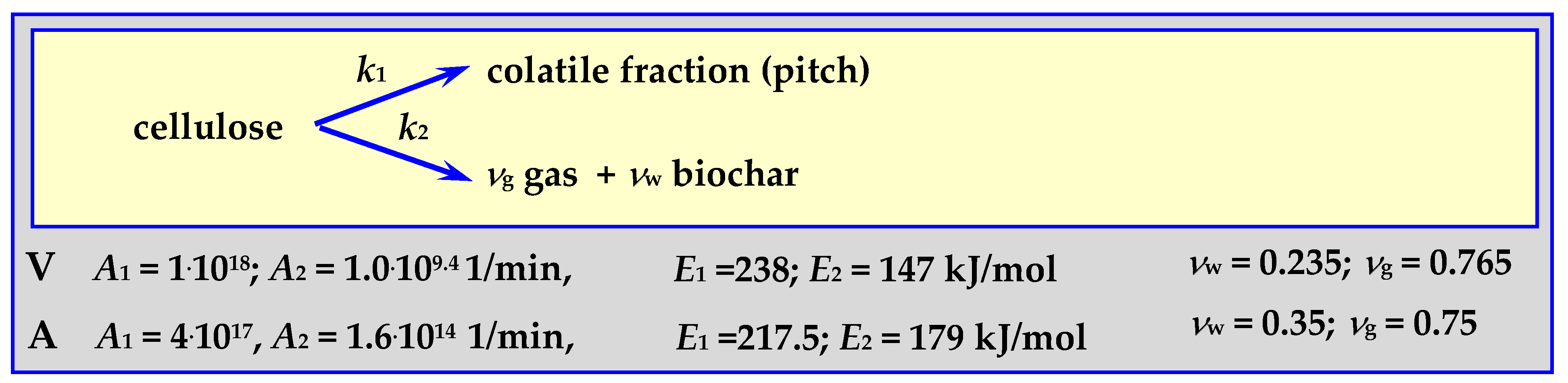
4.3.2. Pyrolysis Kinetics According to the Shafizadeh Mechanism

Parameters of the Shafizadeh mechanism [83] were determined for the pyrolysis of 250 mg of cellulose powder forming a 0.5 cm layer in an isothermal tubular reactor (“S”) [84] for a temperature withing the range of 532 < T < 680 K. The scheme of this mechanism and the determined parameters are shown in Figure 8.

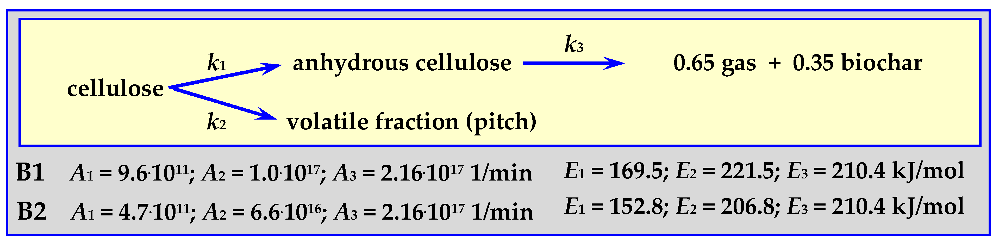
4.3.3. Pyrolysis Kinetics according to the Broido-Shafizadeh Mechanism

The Broido-Shafizadeh mechanism [85] progresses according to the diagram in Figure 9 for T > 703 K, heating rate of 40 K/min, 0.5–3.0 mg cellulose mass—V [86], or for 523 < T < 633 K, 0.076 m thick cellulose discs weighing 90 mg in an isothermal fluidized bed reactor (“A”) [17,34,82].

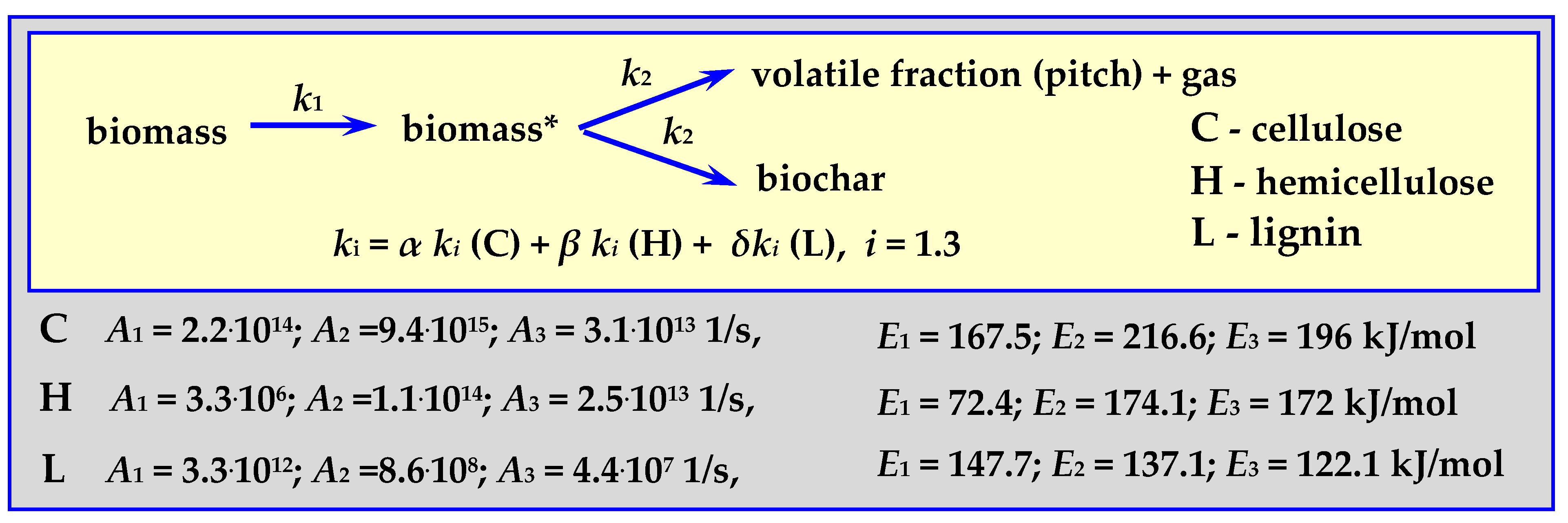
4.3.4. Pyrolysis Kinetics According to the Koufopanos Mechanism

This semi-complete mechanism progresses according to the diagram in Figure 10 (“K” in Figure 12), for a temperature of 573 < T < 973 K, with a heating rate of 5–80 K/min, for 20 mg, 0.3–0.85 mm pieces of wood or other biomass [17,87].

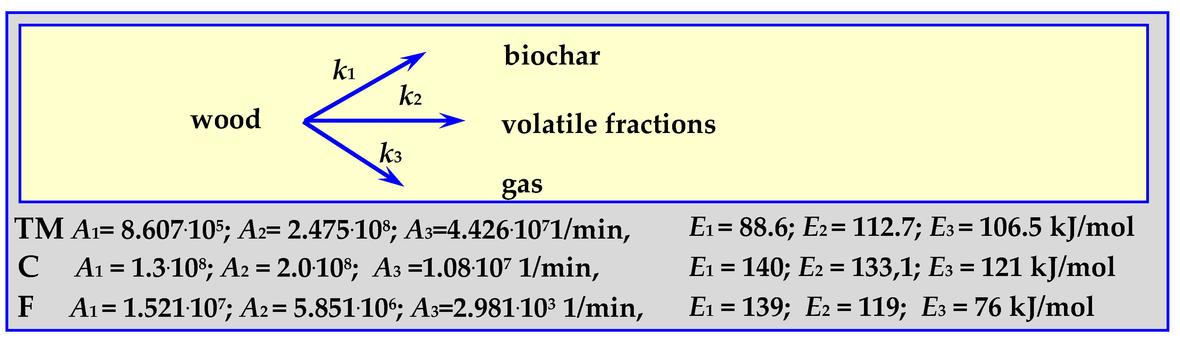
4.3.5. Pyrolysis Kinetics According to the Three-Phase Mechanism

The parameters of this mechanism, shown schematically in Figure 11, were established based on the kinetics of oak wood pyrolysis (“TM”), almond shell pyrolysis (“F”) and according to literature data (“C”) [88]. Pyrolysis of 0.615–1.0 mm oak wood pieces was carried out at a temperature of 573 < T < 673 K, in an isothermal tubular reactor [89], while the pyrolysis of 0.297–0.5 mm almond shells pieces was carried out within the temperature range of 733 < T < 878 K, at a heating rate of 20 K/min (“F”) [17,90].

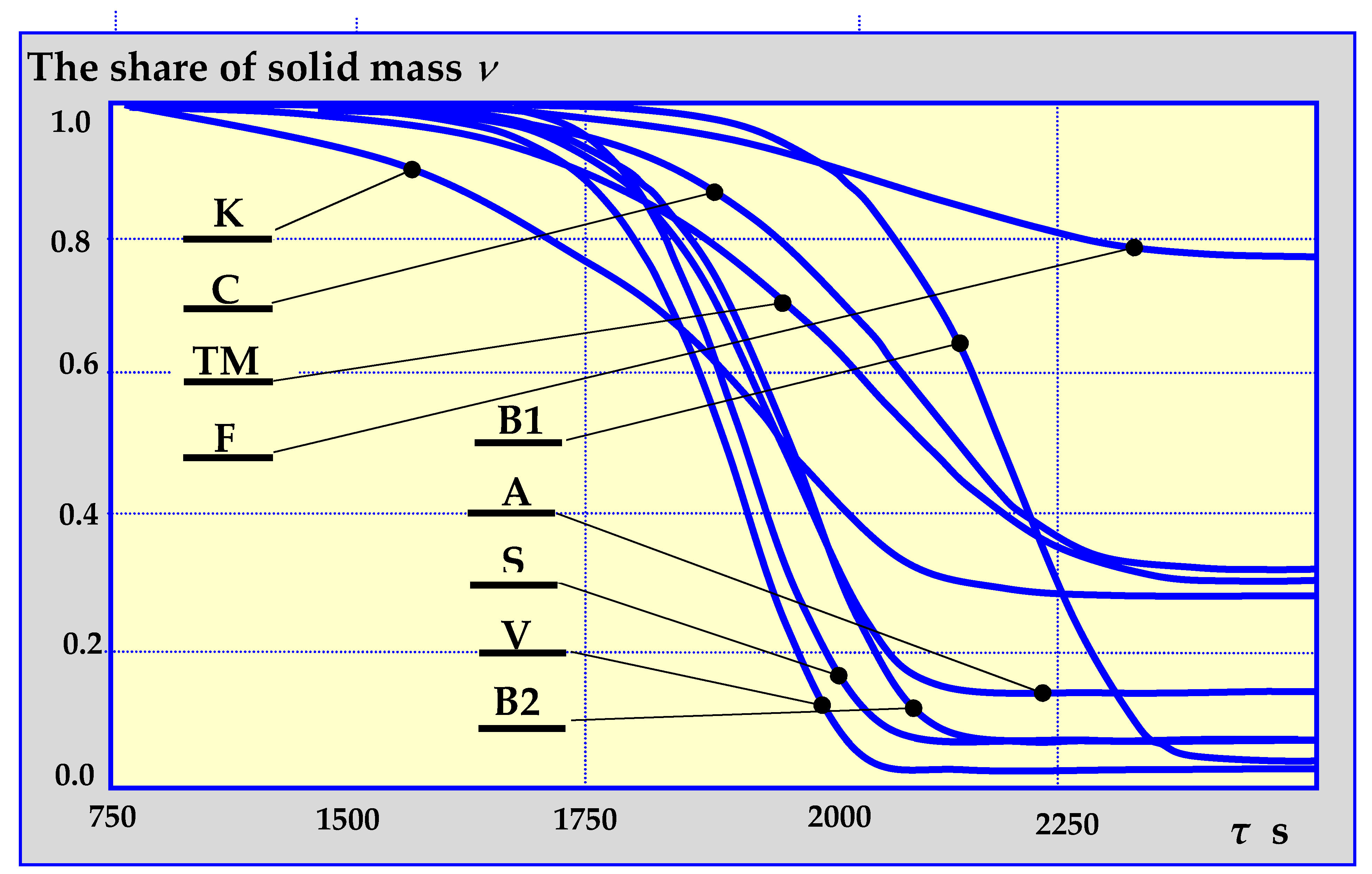
4.3.6. Summary of Pyrolysis Kinetics Mechanisms

The authors in [80] presented the results of comparative studies of biomass pyrolysis kinetics for the previously mentioned pyrolysis mechanisms as a function of solid, gas and liquid fraction shares in decomposition products, depending on the pyrolysis temperature, temperature increase rate, its duration etc. Figure 12 presents a single example of comparative research results.

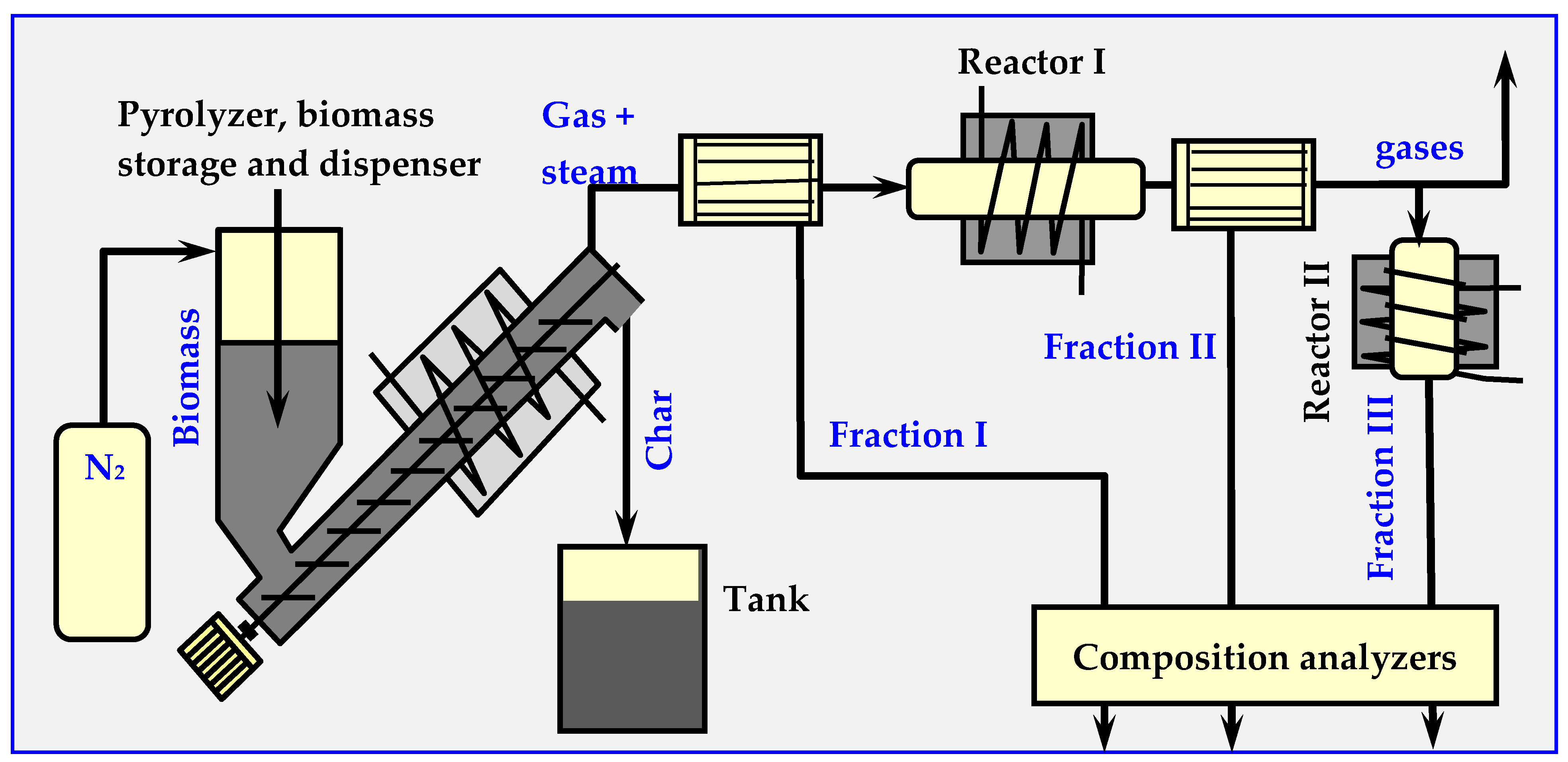
4.4. Experimental Research on Biomass Pyrolysis

Experimental studies of pyrolysis kinetics for willow wood, coal from the “Staszic” coal mine, and a 1:1 mixture of willow and coal are presented in Figure 13 in the form of the rate of CH4, H2, C2H6 and CO emissions as a function of pyrolysis temperature. The total yield of all components of thermal decomposition is shown in Table 1 [17,91,92].
Kinetic studies of biomass pyrolysis (cellulose, xylan, pectins) using a thermogravimetric analyzer (TGA) coupled with a differential scanning calorimeter (DSC), mass spectrometer (MS) and a gas chromatograph (utilized to identify the decomposition products) are presented in [93]. Similar studies for wood chip decomposition are presented in [94].
The decomposition products specify and determine the quantitative relationships of individual components from three classes of compounds: I—for 400–700 °C (acids, ketones, phenols, guanidines and furans), II—for 700–850 °C (phenols, cresols, aromatic monocyclic, xylenes, benzenes etc.) and III—for 850–1000 °C (polycyclic aromatics). The measuring installation diagram is shown in Figure 14.

4.5. Technical Issues of Biomass Pyrolysis

Pyrolysis, like gasification, is a complex process consisting of many stages. Depending on the temperature, as well as on the oxygen content and composition of the introduced biomass, due to oxidation, this process may be exothermic. In general, however, it is endothermic because of the reduction processes. For most types of biomass containing oxygen-rich hemicellulose, the decomposition is endothermic below the temperature of about 400–450 °C, and exothermic above this threshold.
The basic reactions occurring during biomass pyrolysis and their enthalpy values for temperatures t = 300 and 1000 K are provided in Table 2.
It is worth noting the high exothermicity of cellulose carbonization per single C6H10O5 molecule (monomer). This is due to the high carbon content (up to about 35% by weight), which causes its pyrolysis at lower temperatures to become autogenic and not require external heating. This results, however, in a lower hydrogen content in gas products. At lower temperatures, pyrolysis is generally controlled by the rate of reaction, while at higher temperatures the process is controlled by the mass exchange rate.
Thermal pyrolytic decomposition of biomass, carried out in an anaerobic atmosphere, leads to the formation of three forms of products:
Solid:
Biochar—charcoal (in case of wood decomposition) and ash,
Gas:
Oil and pitch (tar), which are a mixture of hydrocarbons, phenols and about 200 various aliphatic and aromatic organic compounds, saturated and unsaturated,
Gas:
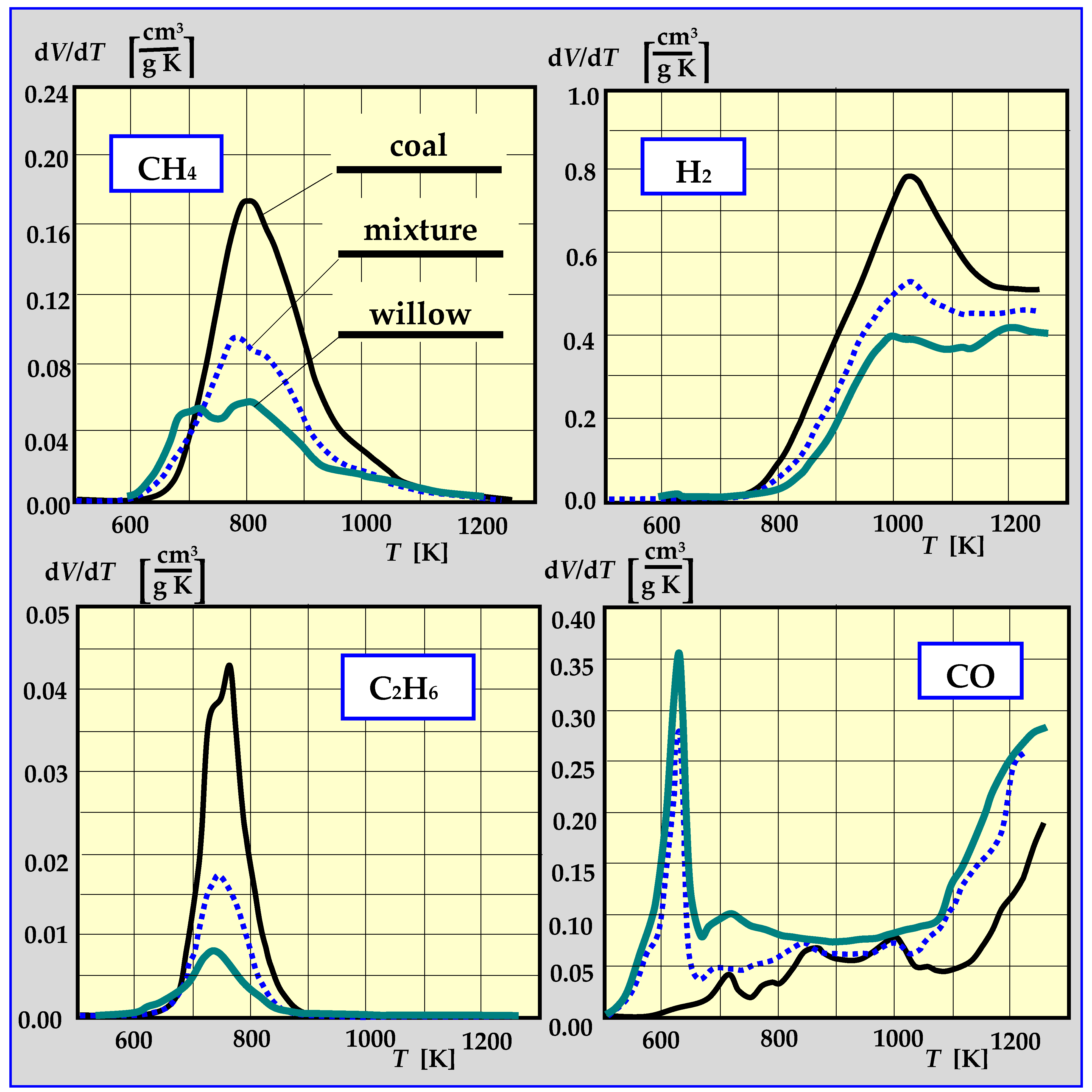
A mixture of CO, CO2, H2, gas hydrocarbons (CH4, C2H6) and liquid hydrocarbons vapors, e.g., C3H8, C4H10 and steam, with a calorific value of approx. 12 MJ/kg. The composition depends on the temperature of the biomass decomposition. For example, for a temperature of 482 °C/926 °C, the composition is as follows (% V/V): 5.56/32.48 H2; 12.34/10.45 CH4; 33.50/35.25 CO; 3.03/1.07 C2H6; 0.71/2.43 C2H2. In total, flammable gases constituted 54.97% of the mixture for 482 °C or 81.68% for 926 °C [95]. The tar from gaseous pyrolysis products can condense at low temperatures and will lead to clogging or blockage in fuel lines, filters and engines [96]. Therefore, it must be controlled and removed.
According to experts [97,98], economically, the largest possible share of liquid fractions in biomass pyrolysis products is the most desirable. In their opinion, the ratios of profits from converting biomass into heat, electricity or liquid fuels are as follows:
Heat: electricity: liquid fuel = 1:3:9
Thus far, the prices of fuels have not been a driving force in the search for new technologies. Currently, however, when the situation has changed and the importance of biofuels has increased, one can predict an increase in interest in thermal biodegradation of biomass towards obtaining as much liquid biofuels as possible from it [99]. Depending on the type of pyrolysis, two types of liquid fuels are distinguished (Table 3):
Liquid primary biofuels, which are formed directly as a result of flash pyrolysis with high yield, up to 85% by weight. These have a relatively low viscosity, mix with water up to 35–50% of water content, easily burn in boilers, furnaces and engines. Compared to petroleum fuels, these fuels are less stable, more sensitive to temperature, and may polymerize after some time.
Liquid secondary biofuels, which are obtained as a result of typical or slow pyrolysis with less efficiency, no more than 20% by weight. These have high viscosity and low water tolerance. When the amount of water exceeds 20% by weight, dissection occurs. These features do not discredit them as fuels, but constitute a certain technical impediment [100].
Energy for biomass pyrolysis can be supplied from an external heat source or from combustion of some of its decomposition products: biochar, oil or gas.
A diagram of a tubular reactor with an external heating jacket for thermal decomposition of biomass is presented in Figure 15. Depending on the parameters of its operation, the amount of steam supplied and the catalysts, the composition of individual products can be adjusted so that it acts as a gasifier, a pyrolyzer or a biocarbonizer.
In the pyrolyzer shown in Figure 15, the decomposition process starts from 200 °C; however, the upper temperature is not limited, and may even reach plasma levels. The final products are pyrolysis gases, oils and biochar (charcoal) or ash [15].
If the device shown in Figure 15 is to work as a pyrolyzer, liquid fractions should be separated from the pyrolysis gases by cooling and distilling in a distillation column.
The ratios of gas, oil and biochar in decay products depend on the temperature increase rate, decomposition time, temperature and pressure. During rapid thermal decomposition, over 65% of biomass is transformed into gas (gasification), at an average rate; over 70% of biomass forms oil (pyrolysis), and during slow decomposition, over 35% of biochar (biocarbonation) is obtained.
Approximately 30% (by weight) of oil can be drained from pyrolysis gas. At room temperature, this oil is a mixture of approx. 200 liquid organic compounds, including hydrocarbons, alcohols, aromatics and others.

4.6. Types of Pyrolysis Reactors

The thermal decomposition of biomass has been carried out for centuries, thus, it is not surprising that the experience gained has resulted in the development of a number of structural and technological solutions. Among these are reactors with combustion, electric, induction, microwave [11] or solar heating, in which heating is achieved through an external diaphragm, internally or through an inert medium (solid—sand, biochar, or gas—nitrogen, flue gas, CO2). The shapes of these reactors are typical: cylindrical (horizontal, oblique, vertical), conical or cuboid.
Biomass flow within these pyrolyzers is carried out pneumatically (fluidized bed, fixed bed), mechanically (auger, stirrer, rotary, ablative, rake conveyor pyrolyzers) or gravitationally [101]. Aside from biomass movement and pyrolysis, mixing (stirrer, circulating fluidized bed (CFB) pyrolyzers) or grinding and crumbling (milling, ablative) can occur simultaneously within these reactors [34,73,102,103].
The biomass bed introduced into pyrolyzers can be fixed, flowing, swirling or fluidized. Schemes of some of these beds are presented in Figure 16 [17]. More information on pyrolyzers is provided in [34,101]. The pyrolyzers described therein are used for processing rubber from used tires. Rubber is, however, a polyisoprene obtained from rubber trees [104], i.e., biomass; therefore, pyrolyzers used for treating biomass and rubber are the same.

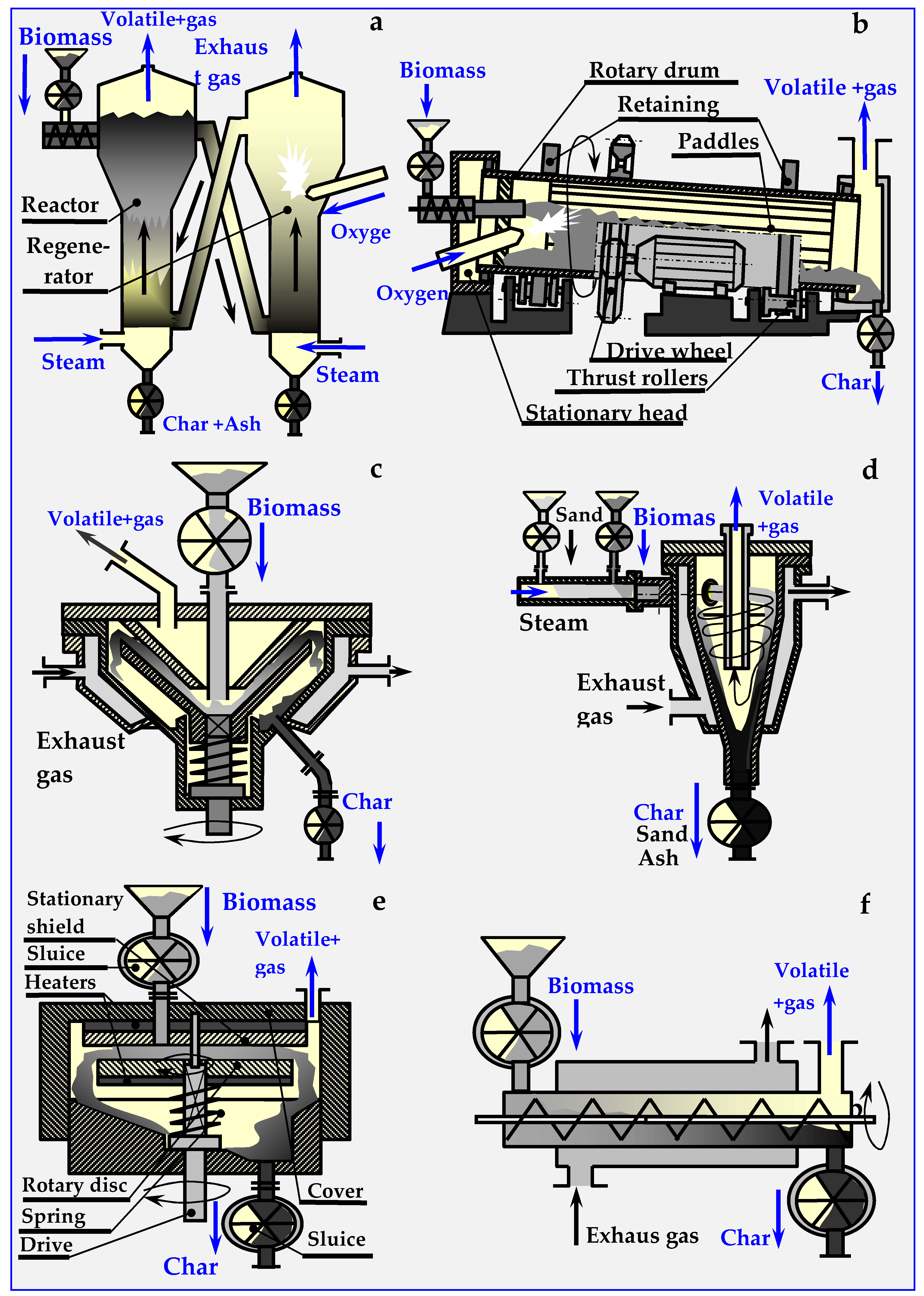
4.6.1. Fluidized Pyro Duiven Lyzer

In a fluidized pyrolyzer (presented in Figure 16a), the process takes place in an inert bed, which can be, for example, sand or ceramic balls. This bed is heated within the regenerator by the heat of combustion of biochar in oxygen or in air introduced into the regenerator through a side connector. The regenerator can also be equipped with an internal auxiliary burner (omitted in the figure), powered by pyrolysis gas or natural gas. The fluidized bed is circulated through lateral oblique channels between the regenerator and the pyrolysis reactor.
Shredded biomass is introduced from above to the hot bed flowing into the reactor from below. Gases and volatile pyrolysis components are discharged to the cooler and distillation column, which have been omitted in the figure, and the residue (ash, biochar and untreated biomass) is poured with the cooled inert bed into the regenerator, where the biochar and biomass finish burning, and the bed is heated. To create a fluidized bed in both columns of the apparatus, steam is supplied under pressure from below the sieve bottoms. Different types of fluidized bed pyrolyzers have been described: conical spouted beds [60,61,62,105], bubbling fluid beds [103,106] and externally or internally circulating fluidized beds [107,108,109,110].

4.6.2. Rotary Kiln Pyrolyzers

The rotary drum (kiln) pyrolyzer shown in Figure 16b is heated by the heat of partially burned biomass. Movement of biomass in this pyrolyzer occurs due to gravity and the oblique position of the drum (2–3°), and the blades circumferentially located along the drum cause pouring and mixing of the charge. Biomass is dosed from the airlock via a feed pipe. A ring of diagonal guide vanes, circumferentially fixed at the beginning of the drum, prevents the backflow of biomass. Despite the use of sealing rings between the rotating drum and stationary heads, biomass dosing sluices, ash dischargers and hydraulic seals, airtightness could not be achieved within this reactor. Anaerobic pyrolysis conditions were achieved only after an atmosphere of inert gas under low overpressure was introduced. The advantages of this pyrolyzer are, however, its simple construction and low price.

4.6.3. Conical Rotary Pyrolyzer

In this pyrolyzer, biomass is fed between two vertical cones: the upper one is stationary and the lower one is spinning. The charge is milled between the cones and undergoing pyrolysis, during which it is converted into pyrolysis vapors and ash. The heat is supplied through the heated, conical side surfaces of the pyrolyzer. The gap between the cones narrows down, allowing only ash to escape into the chute and the drain. Thermal energy is provided by pyrolysis gas, from which liquid components (oils, pitch (tar)) had been previously separated. This gas is burnt in a burner (not marked in the figure), and the flue gas warms the interior of the pyrolyzer through a diaphragm, as shown in Figure 16c [107,111,112].

4.6.4. Cyclone Pyrolyzer

In this pyrolyzer, thermal decomposition of biomass takes place in an inert bed, which is a mixture of biomass and fine heated carrier, e.g., sand. From the dispenser into which biomass is introduced pneumatically through sluices (butterfly, screw or other), the inert bed is transported with a stream of superheated steam tangentially to the cyclone pyrolyzer (Figure 16d). In the swirled stream, additionally heated by exhaust gases through a diaphragm heating mantle, intensive mixing, heating and pyrolysis of biomass occur.
Because of centrifugal force, the biomass and sand are pushed onto the heated walls, and move downward in a spiral motion. Due to the temperature, and the tangential cutting forces of walls and sand, biomass undergoes fragmentation and intensive pyrolysis. Vapors of oils and pitch (tar), together with pyrolysis gas and steam, are discharged from the pyrolyzer overhead, while sand with ash are deposited on the separator sieves. The ash, discharged via a sluice, is converted into fertilizer, and the sand is heated in a mantle exchanger with a screw conveyor and recycled. After cooling, volatile products are separated in a centrifuge into water and oil fractions. Water returns to the steam generator, and oil is separated into individual components in a distillation column.

4.6.5. Ablative Pyrolyzer

In this pyrolyzer, shown schematically in Figure 16e, biomass is introduced between two electrically heated grinding discs. The upper disc with the hole in the center is fixed, while the lower disk is pressed by a spring and rotated by a vertical shaft. During pyrolysis, biomass undergoes intensive mixing and milling. This ensures good surface development, intensive heat exchange and the possibility of achieving rapid pyrolysis, in which a greater proportion of oil than gas is obtained. The anaerobic environment is obtained by hermetically introducing biomass and discharging products with sluices and hydraulic closures, or by introducing a chemically inert, pressurized buffer gas (N2, Ar or CO2) [107,111,113,114].

4.6.6. Auger or Screw Pyrolyzers

An in-pipe pyrolysis device with an internal screw conveyor, transporting and mixing biomass inside a fixed horizontal pipe, is shown in Figure 16f. Heat produced in an external boiler, fired with biomass, oil, gas or coal, is supplied through the walls of the heating jacket. As the cooling of biochar in this pyrolyzer is not possible, it is assumed that, aside from gas and oil, the final product contains ash. A disc variant of this pyrolizer is also viable, in which the ducts should have a rectangular cross-section, and the screw conveyors should be replaced with scraper, shock, inertial or other types of conveyors.

4.6.7. PyRos Pyrolyzer

The design and shape of the PyRos pyrolyzer [115] resembles the cyclone pyrolyzer shown in Figure 16d; however, the vortex movement of the bed together with biomass within the conical reactor is carried out with a rotating blade mixer. Other elements related to the removal and processing of gaseous, liquid and solid fractions remain unchanged.
Additional information on the subject of pyrolyzers, in the context of entire installations for thermal biomass processing, as well as examples of their implementation at semi-technical, technical and commercial scales, especially in the USA and Europe, is provided in [16,46,107,115,116].

4.7. Examples of Pyrolytic Installations

The most popular biomass pyrolysis technologies are summarized in Table 4 [17].
Today, the use of pyrolytic processes is rather common, and the number of companies specializing in these types of installations steadily increases. Below are some examples of the most popular and latest solutions in this field.

4.7.1. BTG Flash Pyrolysis Installation

The BTG Flash Pyrolysis process, also known as flash pyrolysis, involves very fast heating of biomass to a temperature of 450–600 °C in an anaerobic atmosphere. The main product of the process is oil, formed from 70–75 wt. % (by weight) of load. The maximum efficiency of biomass-to-oil conversion (79 wt. %) is obtained at a temperature of about 500 °C. BTG flash pyrolysis technology is based on the use of a rotary cone reactor [101,125,126], at the bottom of which biomass particles are preheated to room temperature, and hot sand particles are introduced (Figure 17). The vortex movement of biomass and the bed causes mixing, milling and pyrolysis, as well as transport of sand and ash upwards. The rotational speed of the reactor cone is 300 rpm. Due to rapid heating of biomass, only 15 wt. % of the charge is converted into biochar, 10 wt. %. is converted into gas and the rest is oil.
The pyrolysis installation with the sand recirculation system includes a pyrolysis reactor, pneumatic lift pipe for sand, a chamber for combusting the biochar in air and a return pipeline. The vapors pass through a series of cyclones and are directed into the radiator for rapid cooling (due to injection of recirculating oil). The main product is oil, and the pyrolysis gases remaining after condensation are combusted in the boiler.
The recovered heat can be used to pre-dry the raw material, since the above-mentioned performance parameters are achieved only when the biomass fed into the reactor is dry (when it contains no more than 10 wt. %. of water).

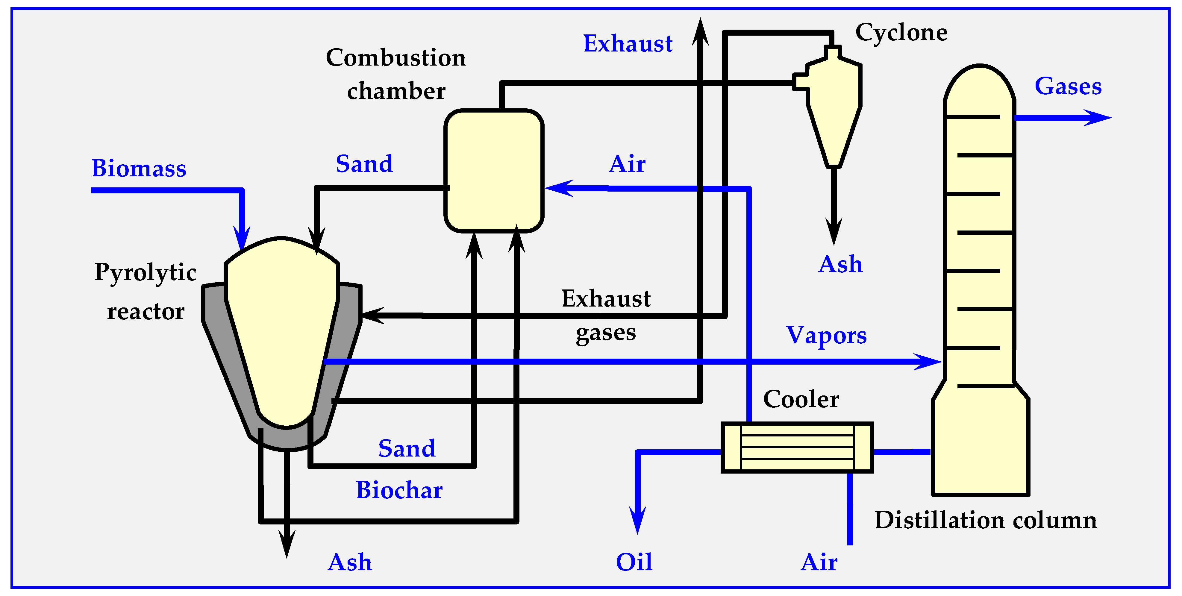
4.7.2. Pyrocycling™ Technology

This technology was developed by a Canadian-Dutch conglomerate. Figure 18 illustrates its simplified diagram. The raw material is air-dried bark of soft trees—waste material from a sawmill, containing approximately 31 vol. % of balsam fir (Abies balsamea), 55 vol. % of white spruce (Picea glauca) and 14% vol. of black spruce (Picea mariana). Biomass humidity at the inlet to the reactor is approx. 10% wt. As a result of pyrolysis, 74.8% volatile parts (gas and oil vapors), 22.3% bound carbon and 2.9% ash are obtained.
The stored biomass is directed to a container with a screw conveyor, which feeds it to a pneumatic transport system ending with a cyclone. In the cyclone, the raw material falls due to gravity onto the vibrating separator sieve. The fraction between 0.5 and 40 mm is directed to the vacuum-sluice supply system (consisting of two rotary cell dispensers, placed in series, between which suction from a vacuum pump is applied). Similarly, biochar and ash are discharged from the pyrolyzer through identical double vacuum sluices. This prevents leaking of the pyrolysis gas from the reactor, as well as the inflow of atmospheric oxygen to the reactor. The process of thermal decomposition of biomass occurs at overpressure of about 20 kPa in a horizontal moving bed reactor [101,127,128,129].
As a result of thermal pyrolytic decomposition, biomass is converted into pyrolysis oil, charcoal (biochar), raw gas and an aqueous fraction. The biochar, which has a temperature of about 475 °C at the reactor outlet, is cooled in three stages in screw heat exchangers, initially with air and subsequently with water. After passing through the vacuum system, the biochar is transported by a belt conveyor, packed into 1.5 m3 bags, and either stored or sold.
Gaseous products, including pyrolysis vapors, are discharged from the reactor through a 600 mm nozzle into a two-stage condensation system (packed columns). Heavy bio-oil condenses in the first column, while a mixture of light bio-oil and pyrolytic water condenses in the second column. This mixture is subsequently separated by centrifugation. Both bio-oil fractions are mixed and collected in 1 m3 polyethylene containers or in a 50,000 L tank. Before discharge to the municipal sewage system, the aqueous fraction is neutralized with a caustic soda solution. The remaining flammable gas from the second column is compressed to 170 kPa and co-burned with natural gas in a molten salt heater. The molten salts provide the energy needed to carry out the pyrolysis reaction through plates inside the reactor.
For greater clarity, Figure 20 omits certain details, such as a vacuum system with vacuum pumps, conveying pumps, a pneumatic transport system, screw conveyors, valves and other elements that are less important for understanding the principle of the installation.

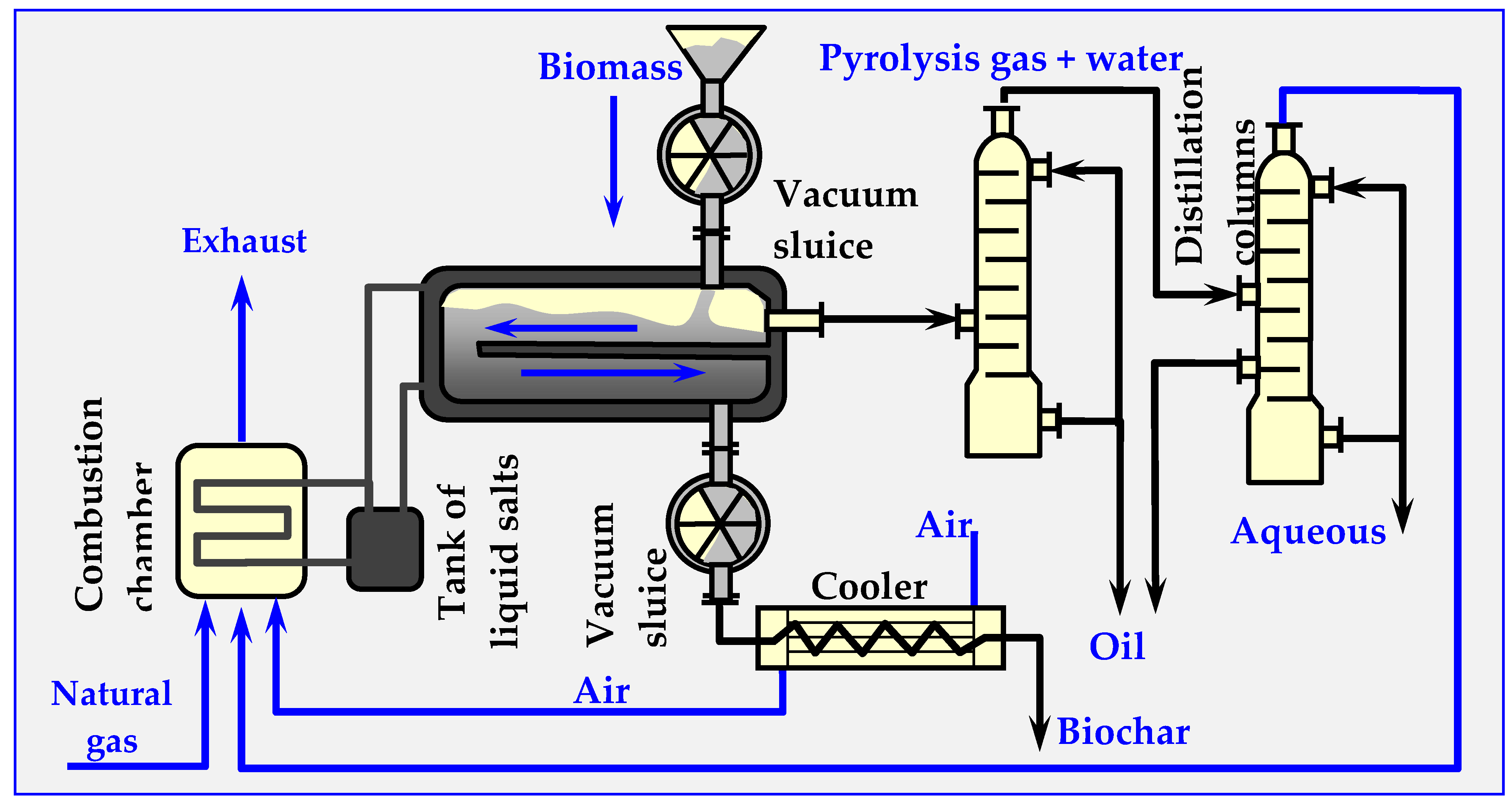
4.7.3. ENTECH Installation for Biomass Conversion

The ENTECH technology of the ENTECH Pyrolytic Gasification System Company with a single module capacity between 0.25 and 125 t/24 h is intended for biomass-based energy production or for the utilization of organic waste, e.g., sewage sludge. The installation consists of two periodically operating devices: a diaphragm-heated pyrolysis chamber and a combustion chamber with a multi-stage air supply, allowing the combustion of raw pyrolytic gas at 1400 °C. Due to the high temperature, it is also possible to utilize hazardous waste (hospital, used medicines, chemical packaging etc.). The energy production capability of the installation is up to 95 MW of thermal energy and up to 20.5 MW of electricity [121].

4.7.4. WGT Technology

The WGT (Waste Gas Technology) hybrid system is a hybrid process combining gasification and pyrolysis technologies [122]. Dried sewage sludge, the raw material in the process, is introduced into the tank acting as a dispenser, to which a buffer gas protecting against oxygen inflow is supplied.
Then, the sludge is directed to a horizontal, cylindrical, rotary reactor heated to approx. 750–850 °C. A high temperature causes pyrolysis of the organic substance, leading to cracking of the gas to hydrogen and short-chain hydrocarbons. Process conditions are strictly controlled to ensure optimal conditions for gas synthesis. The coke breeze generated in the pyrolysis process is separated in a hot cyclone, and the pyrolysis gas is cooled before final treatment.
Unfortunately, due to the WTG Company bankruptcy in 2017, this technology is no longer developed.

4.7.5. Ragailler Technology

This technology was developed by Ragailler Anlagen Technik GmbH [123,130]. Its main component is a distiller—a rotating pipe with a length of approx. L = 21 m and a diameter of D = 3 m. Its interior is diaphragm-heated, which ensures a reductive atmosphere and a small amount of exhaust gasses throughout the process. Uniform heating to a temperature of 450–560 °C allows for full degassing of the raw material in about 1 h.
There is a slight overpressure in the distiller, which eliminates the possibility of air inflow, thereby preventing the risk of explosion. The added dry alkaline sorbents bind 90% of acid components and heavy metals at their release.
Recycling based on dry distillation provides four basic consumer products:
-
Process gas for ecological energy recovery (70%–80% of the energy potential of waste).
-
Coke breeze, i.e., coal with mineral substances contained in waste (20%–30% of the energy potential of waste).
-
Basalt-like aggregate from melted sorbent and mineral substances contained in waste (30%–50% is glass), or boiler slag if the coke breeze is co-burned with fine coal.
-
Ferrous and non-ferrous metals.

4.7.6. HD-PAWA-THERM Technology

The HD-PAWA-THERM process enables sewage sludge utilization and management [131]. Dehydrated and fermented sludge from the supply tank is dried to achieve about 90% of dry matter. The dried sewage sludge in the form of granules is fed to the pyrolysis reactor. In the PAWA process, the residence time of the material in the pyrolysis reactor is sufficiently long (about 1 h). An indirectly heated rotary kiln is utilized as the pyrolysis reactor, in which a high-calorific gas is anaerobically produced at a temperature of 600–700 °C.
The waste solid pyrolytic product is cooled during transport to the storage tank in a mantle screw conveyor. This residue, constituting 10%–15% of the original amount of dehydrated sludge, is biologically inactive and can be stored in landfills. The gas leaving the pyrolysis reactor is subjected to purification and cooling in a washing apparatus, in which condensation of steam and oily components also occurs.
The biodegrading water condensate can be recycled and redirected to raw sewage flowing into the treatment plant. Water-immiscible oil substances are separated in a gravity separator and subjected to material recycling in distillation columns.

4.8. Summary of Pyrolytic Decomposition

The methods of pyrolytic decomposition of biomass discussed in this chapter produce oil that is similar in composition and properties to diesel or heating oil. However, due to low efficiency and high energy consumption of thermal pyrolysis, the costs of production cannot compete with diesel oil production. Further research on the reduction of these costs resulted in the development of new technologies for catalytic pyrolysis of biomass or catalytic synthesis of gas from gasified biomass, which in turn led to the development of second-generation biofuels called SunDiesel, grassoline and others.

5. Biomass Gasification

Due to the strength of the installation, the temperature of gasification and partial pyrolysis should not exceed 1000 °C. At this temperature (700–1000 °C), only a small number of combinations of compounds obtained from biomass decomposition (C, CO, CO2, CH4, H2 and H2O) achieve thermodynamic stability. The proportions of the individual components depend on the temperature, pressure and humidity of the biomass.
Water contained in biomass, separated during torrefaction and pyrolysis or introduced additionally to the gasifier, can endothermically react with the pyrolysis residue and biocarbon, further gasifying it according to:
2 (CH2O)n + n O2 → 2n CO + 2n H2O
m C + m H2O → m CO + m H2
The resulting gas is a mixture of primary pyrolysis gas with water gas. Its calorific value increases by approx. 50% and amounts to approx. 11 MJ/kg [95].
The variability of composition and shares of individual components in the products of pyrolytic decomposition of wood as a function of temperature is presented in Table 5 [132].

5.1. Biomass Gasification Methods

There are two types of biomass gasification: indirect (pyrolytic) gasification, which accompanies pyrolysis and is associated with secondary reactions of biomass thermal decomposition, and direct (specific) gasification, occurring due to steam reacting with the biochar [15,133,134,135,136].

5.1.1. Indirect Gasification

Indirect gasification involves rapid decomposition at a temperature of 700 to 800 °C of volatile components of pyrolysis oil, separated after previous pyrolysis of biomass at T = 600 °C. The result is: CH4 (methane) C2H6 (ethane) and C2H4 (ethylene), which accompany the appropriate gasification products CO, H2, CO2 and H2O. The flammable gas obtained also contains 1%–5% of non-decomposed volatile oil components: polycyclic aromatics, phenols and pitch (tar), similar to products of coal gasification.

5.1.2. Direct (Specific) Gasification

It is an endothermic process requiring a supply of 1.6 to 2.2 kJ/g of thermal energy per one gram of gasified biomass to heat it to a temperature of T = 600 °C. This amount represents 6%–10% of energy available from complete combustion of this biomass. Energy for the biomass gasification process is obtained as a result of partial combustion of flammable gases and volatile components of pyrolysis tar, which are formed in the initial gasification process—incomplete combustion of biomass inside the gasifier. Depending on whether the oxygenator is supplied with pure oxygen or air, the calorific value of the gas obtained varies from Wd = 5800–7700 kJ/Nm3 (air) to Wd = 11,500 kJ/Nm3 (O2). The difference is the effect of N2 content in the air and its NOx oxides, which dilute gaseous products.

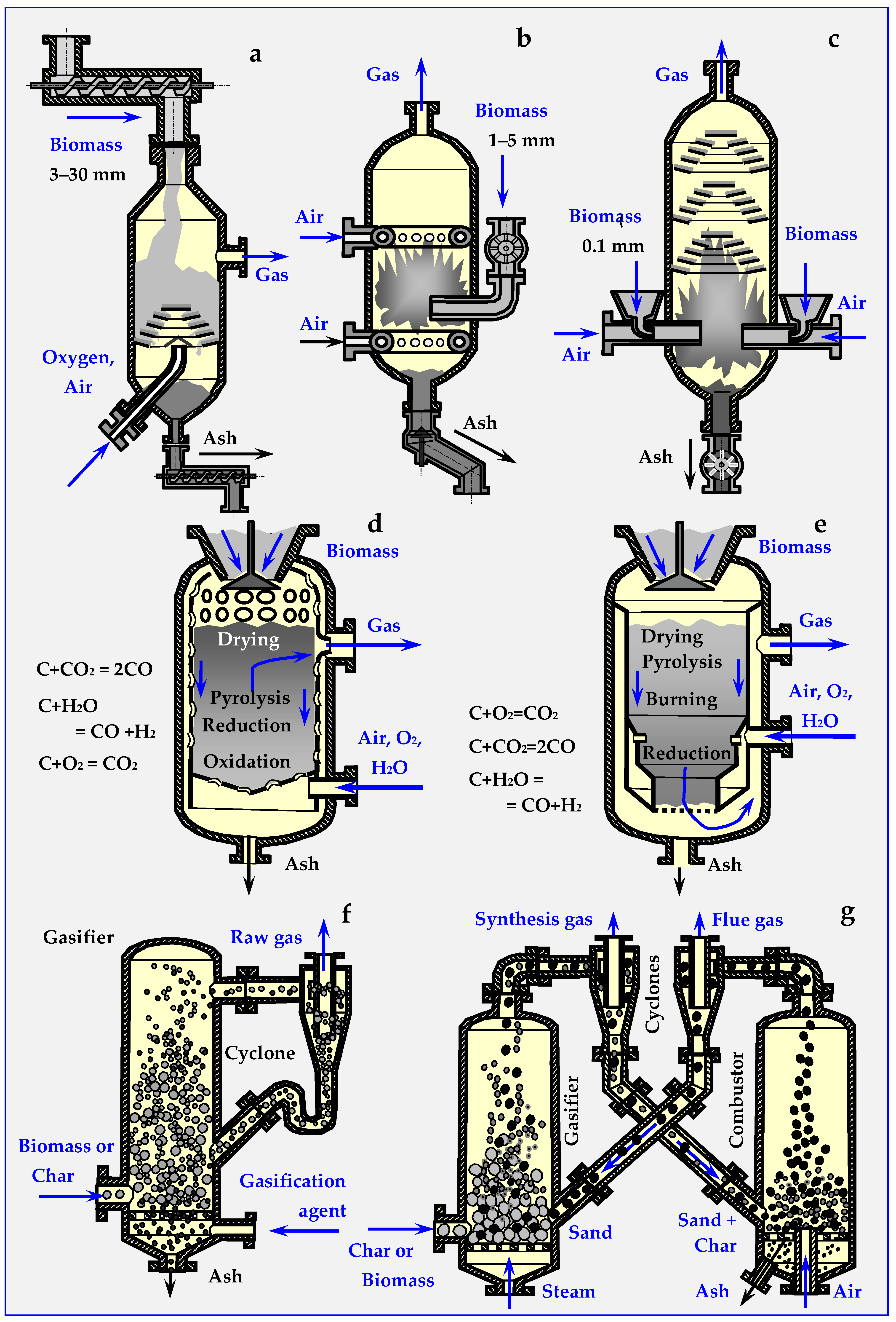
5.2. Types of Biomass Gasification Devices

The gasification process is carried out in closed co-current or counter-current reactors, with a fixed bed, with a fluidized stationary, bubbling, spouted and circulating bed or with an entrained flow [14,15,64,133,134,135,137,138,139,140,141,142,143,144,145,146,147]. The resulting gas, consisting mainly of hydrogen and carbon monoxide, can be burned in a steam boiler, and the generated steam can drive the turbines in a CHP plant. In another variant, biomass gas can drive a gas turbine connected to a generator. Through this method, 1450 kWh of electricity can be obtained from one ton of biomass, e.g., wood with a calorific value of 16.2 MJ/kg [140]. Gas obtained from biomass gasification can also be directly converted into electricity in fuel cells [142].
Depending on the biomass bed, gasification reactors are divided into fixed and mobile bed gasifiers. Their diagrams are presented in Figure 19.
A fixed bed gasifier can work in co-current (updraft), in countercurrent (downdraft) or in crossflow. In countercurrent (Figure 19d), gas movement in the deposit is opposite to gravitational biomass movement, while in co-current (Figure 19e), both movement directions are the same [46,109,148].

5.2.1. Countercurrent Gasifiers

Countercurrent gasifiers are used in installations up to approx. 2.5 MW. Biomass introduced into the reactor through the hermetic sluice moves due to gravity in a perforated pipe, washed with a stream of hot gases, which successively cause drying, heating, slow and fast pyrolysis, and partial combustion of biomass. Simplified reactions limited only to carbon oxidation at individual levels of moving biomass are shown in Figure 19d. The oil and biochar formed undergo reductive gasification to CO and H2 in the presence of CO2 and H2O. The remaining biochar, on the other hand, is burned in the air directed into the reactor with a fan from the bottom connector. Heat generated this way ensures continuous operation of the device.
Before burning the gas obtained in the countercurrent gasifier in a turbine or an internal combustion engine connected to the generator, oil vapors, resins and tar [96] with the approximated formula CH1.2O0.5 must be condensed. The amount of these substances varies from 5% to 20%. This disadvantage is not shared by the gas produced in a co-current gasifier, which does not contain these volatile components.

5.2.2. Co-Current Gasifiers

Co-current gasifiers have a power output of up to 1.5 MW. The entering air in contact not with the biochar, but with the products of biomass pyrolysis, which rise upwards and condense on cool biomass fed from above. These volatile components of pyrolysis move gravitationally with biomass and air to the combustion and reduction zone, where they are gasified. For the average formula of pyrolysis oil CH1.2O0.5 and general remaining liquid hydrocarbons CnH2n+2, gasification reactions in a co-current gasifier are as follows:
CH1.2O0.5 + 0.6O2→ 0.5 CO + 0.5 CO2 + 0.2 H2O + 0.4 H2
CnH2n+2 + n/2 O2→ n CO + (n+1) H2
In the obtained gas the content of volatile liquid components does not exceed 1%; therefore, it can be used directly to power engines and gas turbines.

5.3. Gasification of Biochar

Similar to hard coal [153], biochar can also be subjected to gasification in gasification plants [154]; however, the construction of these plants may be less complicated than in the case of biomass gasifiers, since gasification is not accompanied by pyrolysis, but only by:
C + O2 → CO2 +Q,
C + CO2 → 2 CO,
C + H2O → CO + H2.
Similar to the devices shown in Figure 19, biochar gasification gasifiers can be co-current (d) or counter-current—either with a fixed bed (d,e), or with a moving bed: flow, grate (a), pneumatic (b) or fluidized (f,g). Their construction resembles the construction of devices used for gasification of hard coal [107,133,134,135,155,156].
For energetic reasons, separate biochar gasification is not an optimal solution, because part of the energy must be spent on reheating the obtained biochar cooled down after the process. Therefore, production and gasification should take place in different zones of the same reactor. Fluid reactors can process up to approx. 15 Gg/h of dry biomass, producing from 25 MW to approx. 100 MW of energy.

5.4. Hermetic Dosing of Biomass

From a technical standpoint, hermetic dosing of biomass is one of the most important and most difficult problems to solve in all devices that continuously conduct thermal anaerobic biomass conversion, i.e., torrefiers, pyrolyzers, gasifiers and other. Figure 20 shows the diagrams of sluices, through which ground or crushed biomass can be dosed periodically (gate valve, conical) or continuously (remaining).
The biomass dosing speed can be adjusted by changing the rotation speed of the cages, butterflies, fans or auger. In order to achieve airtightness, it is possible to use two sluices mounted on one pipeline, and to pump out the air from the buffer space between them with a vacuum pump, or inject inert gas into the space.

5.5. Experiments on Biomass Gasification

There are several installations of this type already operational. One example is the cogeneration plant built in 2000–2004 in Gussing (Austria) with hydro-steam gasification of biomass, producing 2 MW of electric power and 4.5 MW of thermal power [157].
The following are some other examples of cogeneration plants operating in Europe, in which energy from gasified biomass is a source of heat and electricity [64]:
-
Lahti Kymijarvi (Finland)—160 MW power output, processing waste from wood, textile and peat industries.
-
Värnamo (Sweden)—launched in 1996, with 6 MW of electrical power output and 9 MW of thermal power output, 80% generator efficiency, and the price of electricity at 33 EUR/MWh, which, given the biomass price of 6 EUR/MWh, bodes well for the future of this technology.
-
In the United Kingdom, a willow-fired (Salix viminalis) power plant project is being implemented with a total output of 8 MW (target output is 35 MW); the willow and Misanthus sinensis plantation area is expected to reach 7000 ha, which, together with waste wood from forests, will provide 150–170 Tg/a of biomass.
-
A reactor producing gas with an energy value of 4.9 MJ/m3 is operating in Bulle, Switzerland; the installation has a power output of 55 kW and gasifies 60 kg/h of waste wood.
-
In Greve-in-Chianti (Italy), gasification of a biomass mixture (poplar, locust bean plant (Robinia pseudoacacia), olive pomace and other waste, mainly from vines) has been successfully achieved. Ultimately, an electricity output of 12 MW is expected.
-
The Swiss company Xylowatt designs and builds biomass gasification installations mainly for developing countries. In the years 1996–2001, India purchased six installations with outputs within the range of 80–2000 kW.
More information on the use of biomass for heat and electricity co-production, as well as on installations operating in Europe can be found on the European BIO CHP website [158].

6. Biomass Gasification by Hydrothermal Reforming

Depending on temperature and pressure, hydrothermal carbonization can be divided into two basic ranges: under subcritical and supercritical conditions. The division limit is determined by the critical parameters of water: critical temperature (374 °C) and pressure (22 MPa) of water [159]. In the subcritical range (hydrothermal carbonation (HTC), primary hydro char recovery can be maximized by limiting the reaction temperature to about 120–220 °C. In temperatures between 220 °C and 280 °C, “secondary” char similar to lignite and sub-bituminous coals is obtained. In both cases, the share of solid fraction is increased at the expense of minimizing hydrothermal liquefaction and gasification [160].
Studies of Herguid [161], Amine [162], Tester [163] and others [73] have shown that the composition of products of hydrothermal decomposition of biomass depends on the amount of steam, pressure and temperature, but also on the moisture of the biomass. The efficiency of hydrothermal gasification of dry biomass was higher than that of wet biomass, regardless of the type of oxidant (air, oxygen, steam). Further research by Yoshida [164] confirmed this effect quantitatively. Despite the same high pressure and temperature, and a constant amount of steam, biomass gasification efficiency decreased from 61% to 27% with an increase in humidity from 5% to 75%. Investigating the causes of this phenomenon has led to the discovery of a more efficient method of gasification of biomass using water or steam under supercritical conditions.

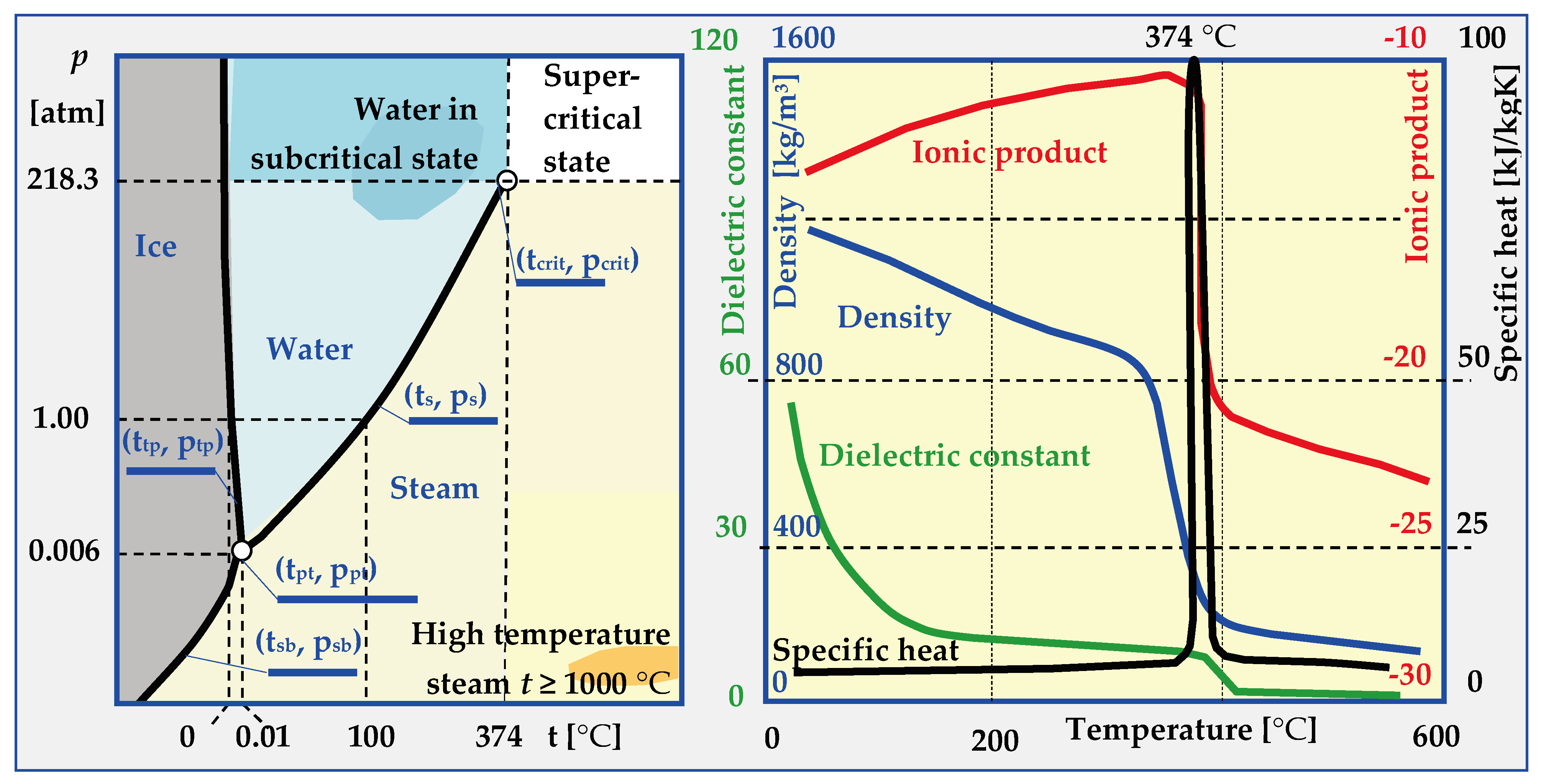
6.1. Physical States of Water

In most cases, knowledge about water is reduced to awareness of its three states of matter. Based on constant temperatures of water’s phase transitions in nature (0 °C and 100 °C at atmospheric pressure), a scale was proposed by Celsius in 1742, which remains in effect to this day. The physical properties of ice, water and steam are also very well known, as are the phenomena such as inversion of water density at 4 °C, 10% increase in volume during freezing, dissociation, polarity, lowering of the boiling point under reduced pressure etc. However, above the critical temperature (tcrit. = 374.29 °C) and critical pressure (pcrit. = 22.089 MPa), physical properties of water drastically change, as shown in Figure 21. After exceeding the critical parameters, which are different for different substances, the boundary between the liquid and gaseous state disappears, and the properties of the resulting supercritical phase differ significantly from water and dry saturated steam (Table 6).
Depending on the water t and p parameters, expressed in temperature values for sublimation tsb = f(p), triple point ttp = 0.0098 °C, melting tmp = f(p), saturation ts = f(p) or critical temperature tcrit. and pressure psb = f(t), ptp = 0.000613 MPa, ps = f(t) and pcrit., several ranges of conditions and states of water occurrence can be distinguished:
-
Normal, in which water is a solid (t < tpt and p > ptp or t < tsb and p > psb), liquid (ttp < t < ts and p > ps) or vapour (t > tsb and p < ppt or t > tpt and p < ps).
-
HCW (High Compressed Water), in which the parameters of hot compressed water are within the range: 250 °C < t < tcrit and p < pcrit.
-
Sub-critical when water or steam parameters are within the ranges: 250 °C < t < tcrit and p > pcrit (for water and t > tcrit and p < pcrit (for steam),
-
SCW (Supercritical Water), when (t > tcrit and p > pcrit) and, depending on the pseudo-critical temperature t*, water is in the form of a pseudo-liquid or pseudo-vapor.
-
HiTS (High Temperature Steam), when steam has a temperature of t ≥ 1000 °C, which is much higher than the critical temperature t >> tcrit., and the pressure is below critical p < pcrit.

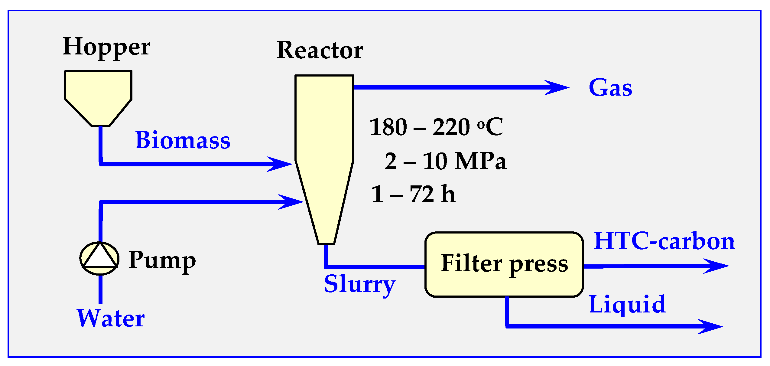
6.2. Hydrothermal Carbonization (HTC)

The main purpose of hydrothermal carbonization (HTC) of most biomass is converting it at 180–220 °C and under a pressure of 2–10 MPa into biochar. This process is more economically profitable the shorter it lasts (optimally up to 3 days). It is similar to naturally occurring biomass carbonization, which resulted in the formation of hard coal millions of years ago. However, due to shorter time and lower temperature and pressure, HTC does not result in full mineralization and recrystallization, as was the case with hard coal, or partial mineralization, as in case of brown coal.
Hydrothermal carbonization is one of the most promising and future-oriented methods of thermal conversion of biomass waste, because, due to relatively low temperatures and the possibility of processing moist raw materials that do not require pre-drying, it is the least energy-consuming. However, the mechanism of this process is very complex [166] and has still not been fully explored [167,168,169,170,171,172]. The yield of biochar obtained from this process is at around 35%–65% of dry charge with a calorific value of about 13–30 MJ/kg.
The results presented in [169] for Miscanthus and in [172] for olive wood waste show that due to hydrothermal treatment of these wastes, energy densification for Miscanthus increased up to 40% per hectare with simultaneous reduction of dry matter loss. It was also noted that HTC at 200 °C reduces the content of alkali metals in the fuel, and further reduces the content of silicon and calcium in the fuel, although this improves the ash deformation temperature only slightly, suggesting limited improvement in slag propensity. At 250 °C, HTC causes a significant increase in carbon density and the removal of oxygen functionality. The obtained biofuel achieves an HHV (higher heating value of fuel) in the range of 27–28 MJ/kg for early-harvested and 25–26 MJ/kg for conventionally-harvested Miscanthus [169]. The hydrogenation processes lead to an increase in high calorific value of biochar, up to 27.257 MJ/kg (peak temperature 250 °C) with an appropriate Energy Densification Ratio (EDR) of 1.37 (compared to the starting material). In case of torrefaction of olive wood waste, obtaining the same product parameters (EDR and high heating value of 27.206 MJ/kg) required a temperature higher by 50 °C than in case of hydrocarbonization (300 °C peak temperature), which proves its lower energy consumption [172].
Hydrothermal material recycling of olive pressing waste with a typical wet basis mass composition (olive pulp—39% wt., kernels—5% wt. and olive mill wastewater—56% wt.) is presented in Reference [173]. The HTC tests carried out in this work at 180, 220 and 250 °C in a 2-L batch reactor, electrically heated for 3 h, showed the effect of temperature on the value of the energy concentration coefficient in the obtained granulate; the maximum coefficient value achieved was 142%. The research also established that, based on the content of mineral substrates, nutrients and polyphenolic compounds in HTC liquid fractions, HTC residues can be used as valuable natural liquid fertilizers [173].
In turn, the use of HTC for utilizing watermelon skin waste is described in [174]. For a temperature of 190–260 °C, and times 1, 6 or 12 h, the yield of hydrochar was at 2%–5% (fresh matter) and 46%–95% (dry matter). However, for lower temperatures (190 °C), an increase in conversion efficiency was achieved, and the following changes have been observed in the product (compared to the feedstock):
  • An increase in C/N ratio (22.19–26.86),
  • More alkyl C, aryl C and carbonyl C,
  • Lower H/C (0.98–1.22) and O/C ratios (0.13–0.38),
  • Less O-alky C, carboxylic C.
Thermodynamics of hydrothermal carbonization have been described in detail in References [171,173,175,176], with the typical hydrothermal carbonization described in Figure 22.
Besides converting wet biomass into biochar, the HTC process is also capable of co–producing phenolic compounds and aldehydes that can potentially be used in biorefineries [177]. The formation of these chemicals in appropriate concentrations can be controlled by controlling the temperature, pressure and duration of the HTC process.
Detailed data on this application of HTC are provided in [4], where a constantly operating pilot installation with a daily capacity of 1200–2400 kg of biomass (on dry base, between 8 and 16 h operation time) was described. In this installation, wet biomass at reaction temperature (>200 °C) was fed into a vertical cylinder reactor through a preheated tube entering at the bottom. The gases can be released at the top of the reactor, while the carbon outlet is also placed at the bottom. The presented data were obtained mainly from processing garden pruning biomass. The solid product was separated from mainly inorganic particles (inorganic biomass contaminants).
Usually, no additional catalyst is used in this HTC technology, and due to fairly uncomfortable pressure requirements, the costs can be relatively low. However, this is not a simple technology, as can be concluded from [160]. In this paper, the effects of processing parameters on solid and energy yield in a function of temperature of 120–280 °C have been analyzed. While the amount of extractable “secondary” char briefly increases at carbonization temperature in the range of 220–240 °C, unfortunately, after the temperature exceeds 260 °C, the amount this char decreases. The surface of the as-carbonized hydro-char were dotted with amorphous carbon, comprised of organic acids, phenols, and furfurals.
Although relatively new, the HTC process is already utilized on a small scale in Hokkaido, Japan, where a small hydrothermal treatment plant (1t batch) is processing municipal solid waste (MSW) into biochar and fertilizers. The installation works based on the technology developed by the Tokyo Institute of Technology [178]. The first European installation of this type was established in 2010 in Karlsruhe, Germany and was built by the Swiss company AVA-CO2 [179]. The installation has an annual capacity of 8400 t and can handle a large amount of inorganic substances occurring in the industrial processing of industrial and municipal waste. Despite the first positive reports on the development of this technology, further research and development is needed to determine the impact of initial raw material changes and to assess the life cycle of this method for waste treatment [167,180].

6.3. Water Properties in Supercritical State

Above the critical pressure, there is no temperature of phase transition of water into steam (ts saturation temperature); however, there is a pseudo-critical temperature t*, which determines the transition of water, depending on the pressure p* > pcrit from the pseudo-liquid state to the pseudo-vapor state. The relationship between these parameters is as follows [181]:
t* = (p*)F, F = 0.1248 + 0.01424 p* − 0.0026 (p*)2, t* = ts/tcrit and p* = p/pcrit
In Reference [181], thermodynamic values of supercritical water for pcrit = 22.1 MPa and temperatures within the range of 275–845 K have been provided. For example, for T = 645 K (Tcrit = 647.43 K) these values are as follows: specific volume vkr = 0.002132 m3/kg, internal energy ucrit = 1831.2 kJ/kg, enthalpy hcrit = 1878.3kJ/kg and specific entropy scrit = 4.088 kJ/kg K.
Under supercritical conditions, water becomes nonpolar, as evidenced by a change in the value of its dielectric constant, which at t = 400 °C and p = 25 MPa, is 7.5% of the value in relation to water under normal conditions. This is the result of breaking of hydrogen bonds at elevated temperatures. In supercritical water (t = 400 °C and p = 25 MPa), there are 65%–70% less hydrogen bonds than in water under normal conditions, and with a further increase in temperature (t = 500 °C and p = 25 MPa) this number decreases even further to 10%–14%. The consequence of this is a change in solubility in SCW, in which polar and ionic substances, and therefore inorganic compounds, cease to dissolve. For example, the solubility of NaCl decreases from 40% wt. at 300 °C to 100 ppm at 450 °C. In turn, the solubility of non-polar substances, such as O2, gasoline and other organic compounds in water, in SCW increases significantly.
In the subcritical and supercritical states, the concentration of hydronium (H3O+) and hydroxyl (OH) ions is over 25 times higher than in water under normal conditions. Because of this dramatic change in the ionic product (Figure 21), at these temperatures, water becomes an acid/alkaline catalyst.
The viscosity, density and coefficient of the thermal conductivity of water in both supercritical and subcritical states decrease as shown in Figure 21 and Table 6; however, in addition to these values, the surface tension also decreases. All this, combined with the fact that water in subcritical and supercritical states has an additional significantly higher diffusion coefficient, causes the processes of heat, mass and momentum exchange to take place practically without restrictions. Due to this, water is a good solvent, catalyst and a reagent in synthesis reactions, as well as in thermochemical, hydrolytic or oxidative gasification of biomass to flammable gases with high hydrogen content.

6.4. SCW as a Biomass Gasification Medium

Supercritical water (SCW) is an ideal medium for biomass gasification, especially wet biomass (algae, kelp, activated sludge from sewage treatment plants, feces), because drying of wet biomass before gasification is energetically and economically unprofitable. In addition, the obtained gas no longer requires expensive re-compression for storage, transport or combustion.
Additional advantages of SCWG (Supercritical Water Gasification) over traditional thermal biomass gasification are:
-
Higher efficiency: for example, 80% humidity biomass gasification increases for SCWG from η = 10% to η > 70%,
-
Pitch (tar) content in gas products remains trace, tarry compounds (aromatic, polycyclic phenol compounds) completely dissolve in SCW and undergo reforming, while the remaining compounds pass into the aqueous fraction and do not pollute the waste gas.
-
The amount of residual biochar is negligible, and biochar also transfers into the aqueous fraction,
-
Hydrogen content in final gas products is higher and CO content is lower than in traditional gasification. Additionally, hydrogen is already compressed, which facilitates its further practical use,
-
Heteroatoms and halogens, such as S, N, Cl, which may occur in biomass during SCWG gasification transfer to the aqueous fraction, where their neutralization is much simpler and cheaper than removal from the exhaust gas.
Biomass gasification reaction with supercritical water and without a catalyst at t = 500–750 °C, or with a catalyst at t = 350–500 °C progresses as follows (biomass represented by glucose or cellulose):
2 C6H12O6 + 7 H2O → 15 H2 + 2 CH4+ CO + 9 CO2
or
C6H12O5 + 7 H2O → 12 H2 + 6 CO2
The gasification reactions summarized above also cover partial component reactions, among which are such processes as: hydrolysis, pyrolysis, reforming, methanation and especially oxidation.

6.5. Oxidizing Properties of Supercritical Water

Supercritical water is a very effective oxidizer in SCWO (Supercritical Water Oxidation). It is able to decompose and, thus, neutralize durable and usually very toxic organic compounds present in sewage and waste, such as PAHs (polycyclic aromatic hydrocarbons), pesticides, PCBs (polychlorinated biphenyls), dioxins, insecticides and chloroorganic compounds (HCH, CCl4, DDT, HCBD). Below is an example of oxidative decomposition of PCB with supercritical water, where the reaction efficiency is 99.9% and it takes just a few seconds:
C12H10-mClm +(29-m)/2 O2 +(m − 5) H2O → m HCl +12 CO2
The organic compounds of other elements (sulfur, phosphorus, nitrogen) are decomposed in a similar way; the removal of these elements from gas in the form of inorganic compounds is no longer a problem [24]. Some of the oxidation reactions are as follows [165]:
2C6H4SH + 17O2 → 12CO2 + 5H2O +2SO2 (for tiobenzene),
2CHCl3 + O2 + 2H2O → 2CO2 + 6HCl (for chloroform),
4CH3-C6H2-(NO2)3 + 21O2 → 28CO2 + 10H2O + 6N2 (for 2,4,6- trinitrotoluene (trotyl))
Therefore, SCWO technology provides many possibilities of utilizing hazardous waste.

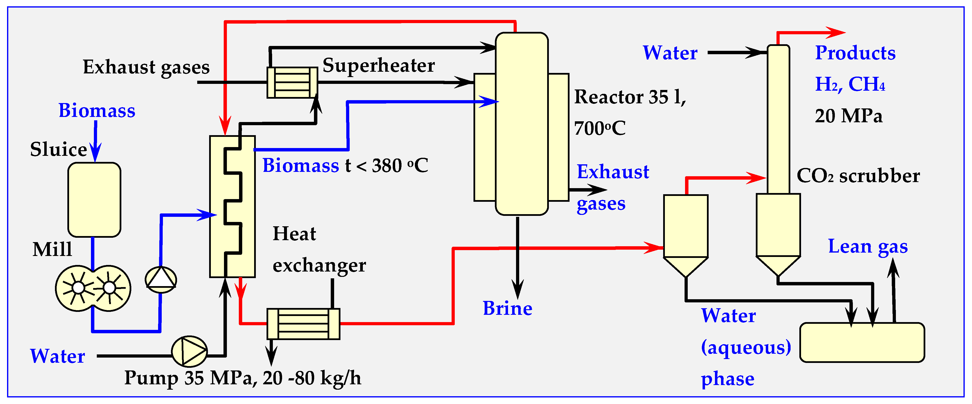
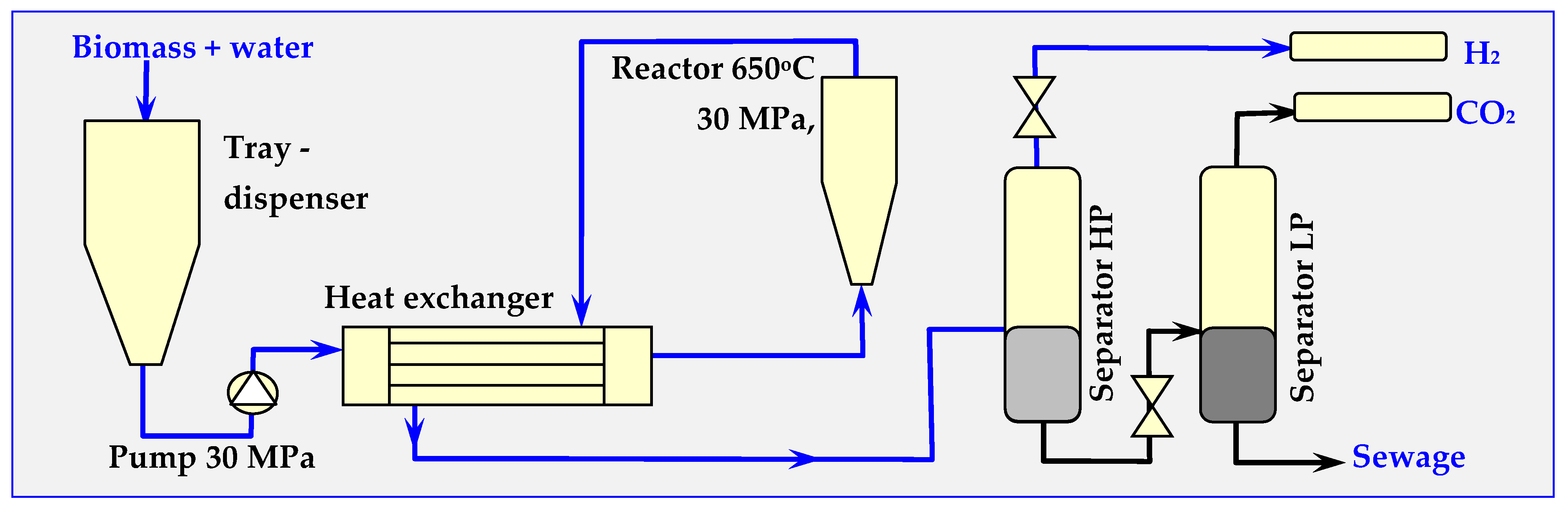
6.6. Examples of Using SCW for Biomass Gasification

Installations for hydrothermal gasification of biomass tested in the Netherlands, Germany, Japan and other countries are currently working on a technical or semi-technical scale. Their main objective is testing the SCW method in practice and gaining as much experience as possible to avoid mistakes in an industrial prototype solution. Scheme of the VERENA pilot installation launched in Karlsruhe in 2002 with continuous operation and a maximum throughput of 100 kg/h at 28 MPa and 660 °C is presented in Figure 23 [182].
In this installation, the maximum pressure and gasification temperature for dry biomass (max. humidity 20%) are, respectively, 35 MPa and 700 °C; however, the efficiency at these parameters is lower.
A similar PDU (Process Development Unit) installation, but on a laboratory scale, was launched by the Biomass Technology Group in Enschede in the Netherlands, in cooperation with the University of Twente. The parameters of this continuous pilot installation, presented schematically in Figure 24, are as follows: t = 600–650 °C, pressure up to 30 MPa, capacity from 3 to 30 kg/h of biomass and a residence time of raw materials in the reactor of 10–120 s.
After partial cooling in the exchanger, the gaseous end-product from the reactor is transferred into two separators: high-pressure (HP) separator, in which, at t = 25–100 °C and p = 30 MPa, a gas enriched in H2 is released (approx. 63% by volume), and subsequently, put into a low-pressure (LP) separator, in which, at t = 20 °C and p = 0.1 MPa, a gas containing mainly CO2 (72% vol.) and small amounts of H2 (approx. 16% vol.) is produced.
Wine production in the oldest 15 member states of the European Union (15.7 million m3/a) is accompanied by the production of 4.7 million t/a of organic refuse with 70% humidity. In order to enable the utilization of this environmentally-harmful waste (due to ethanol content), the development of a technology for its SCWG gasification (Supercritical Water Gasification) has started. For this purpose, it was decided that a prototype gasification installation will be constructed (t = 600 °C, p = 35 MPa, with a capacity of Q = 10–30 L/h and a heating power of N = 20 kW). The installation will produce pure, hydrogen-rich gas for fuel cells or for steam and electricity production [186]. After the construction and testing of the prototype installation, as well as conducting an economic analysis and LCA (Life Cycle Analysis), the next step of the project will be the construction of a demonstrational SCWG installation with a capacity of 0.1 m3/h of wet biomass and 1 MW power output. The project coordinator is Kompost Bauer company from Bad Rappenau [186].

6.7. SCWG Reactors for Biomass Gasification

Currently, intensive work is underway on designing a SCWG reactor for biomass gasification using SCW. Based on existing solutions, these reactors be divided into two types: periodical or continuous. These can be divided further, based on shape of the reactor, degree of biomass fragmentation and the method of biomass introduction into the following types of SCWG reactors:
-
Autoclaves,
-
Steel tubular reactors,
-
Mixers,
-
Quartz capillaries,
-
Reactors with a fluidized bed [73].

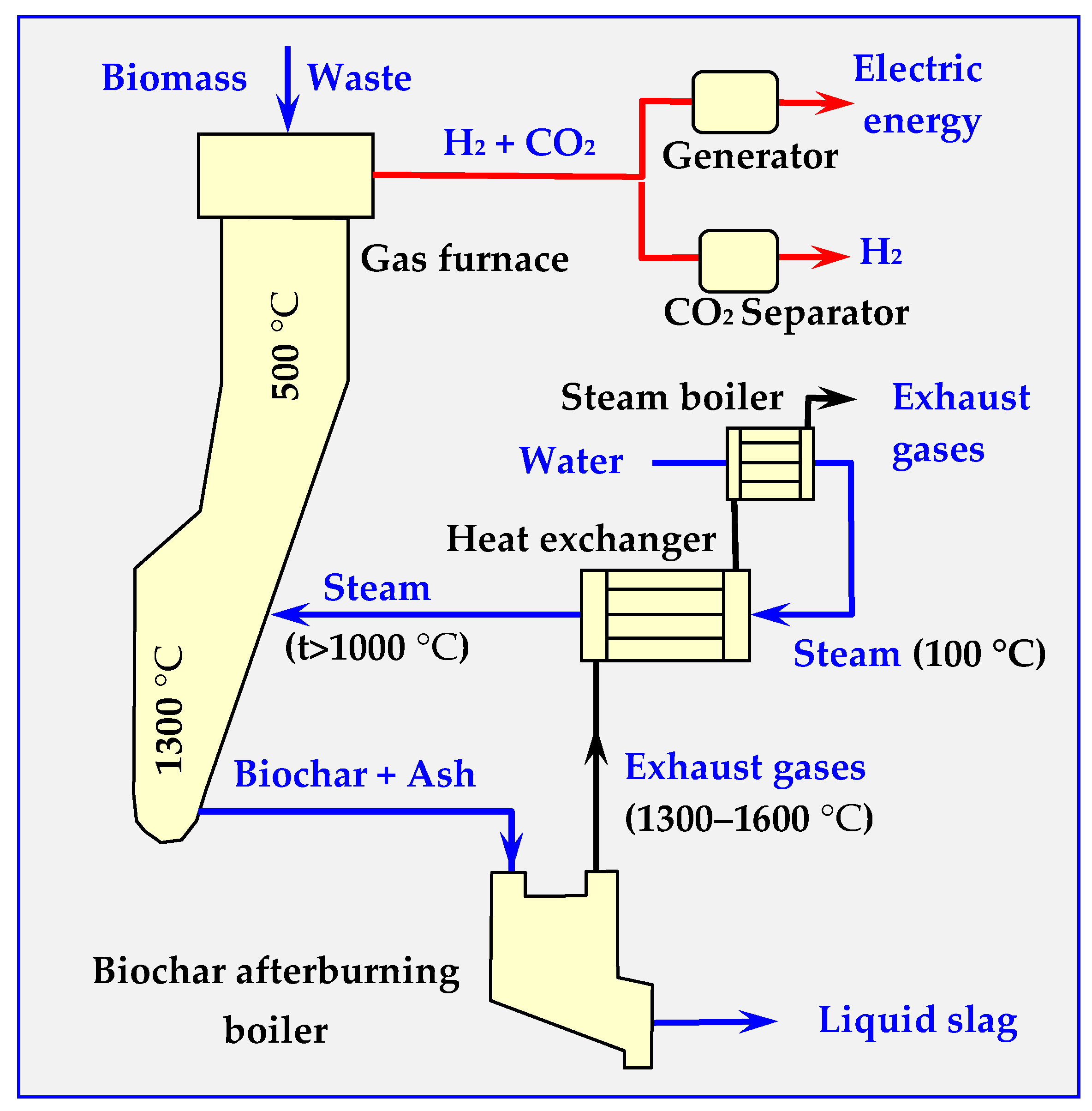
7. Biomass Gasification with High Temperature Steam

Similar to supercritical water, high temperature steam HiTS has strong oxidizing properties and can be used both for hazardous waste disposal and for biomass gasification. Compared to other high-temperature gasification methods, such as high temperature air combustion HiTAC or HiTAG (High Temperature Air Gasification), this technology provides:
-
Uniform distribution of temperature field in the gasification chamber,
-
Lower fuel consumption,
-
Lower emissions,
-
Lack of nitrogen in gaseous products [187],
-
Greater hydrogen production efficiency, as demonstrated by the following reactions:
Cm Hn + (m/2) O2m CO + (n/2)H2 (HiTAC),
Cm Hn + m H2O → m CO + (m + n/2) H2 (HiTS).
Technical implementation of this method, called HyPR-MEET (Hydrogen PRoduction MEET), is one of the most promising technologies of hydrogen production from waste or biomass [97]. At temperatures above 1000 °C, steam molecules break down into radicals that react with biomass according to the following formula [49,152,188,189]:
m CO + m H2O → m CO2 + m H2.
The HyPR-MEET installation scheme is shown in Figure 25.

The Future of SCWG Technology

Biomass gasification technology with SCWG supercritical water or HiTS high temperature steam is not yet developed on an industrial scale. For the time being, operational tests of pilot installations on a technical or semi-technical scale are underway. Several technical problems remain to be solved, related to the strength of materials at high temperatures and high pressures. The reactors must have very thick walls—for example, for a diameter of D = 1 m, p = 35 MPa and an acceptable coefficient of tearing strength kr = 150 MPa, the wall thickness exceeds g > 0.1 m. Smaller reactors may have thinner walls (D = 0.5 m, g = 0.06 m), but do not guarantee industrial efficiency.
Another problem that needs to be addressed is the increased corrosiveness of water under these conditions. The chromium-nickel steels used thus far in the chemical industry under SCW conditions are insufficient. This requires the use of very expensive, new generation construction steels containing titanium and its alloys, as well as other additions, such as Mo, Nb, Ta, Pt, Rh and Ir.
Poor solubility of inorganic salts in SCW is also a disadvantage. Precipitation of these compounds in the installation can cause blockage and seizing of pumps, dispensers and valves, as well as an increased resistance of flow of raw material streams.
In turn, macromolecular organic compounds, which are highly soluble in SCW, can undergo polymerization and form tar-like products or biochar, which are insoluble in the reaction conditions. These can settle on the surface of the reactor or in the flow lines, thus impeding heat exchange [165].
The energy balance is also an important problem, because the profitability of the entire enterprise depends on it. If this biomass conversion technology does not have a positive energy balance, which is a condition for paying back loans and achieving future profits, no one will invest in it.
Negative energy balance of SCW technology is acceptable only in the case of recycling halogen-based high-molecular plastics, or the destruction and utilization of hazardous, toxic or environmentally harmful waste and sewage [165]. In such cases, ecological aspects are more important than economic considerations, and the costs of the project will have to be covered by the taxpayers.

8. Summary

The authors of this study believe that the information on thermal biomass conversion presented within is subjective and sufficiently concise, yet not very extensive. This makes it easier to see similarities and differences between individual biomass conversion methods and devices for its implementation. The focus was on torrefaction, pyrolysis and gasification, while biomass combustion was deliberately omitted. The combustion of waste biomass is not very environmentally friendly, but an acceptable method of utilization. On the other hand, combustion of full-value biomass without recovering and reusing biochar, oils and gases is definitely harmful to the environment. The authors compensated for the omission of combustion by enriching the part of the study devoted to gasification with high-temperature gasification of biomass and biochar using steam and supercritical steam.

Author Contributions

Conceptualization, W.M.L. and M.R.; Formal analysis, M.R. and W.K.; Investigation, W.M.L., M.R., and W.K.; Project administration, W.K.; Supervision, W.M.L.; Validation, W.M.L., M.R. and W.K.; Writing—original draft, M.R. and W.M.L.; Writing—review & editing, W.M.L., M.R. and W.K. All authors have read and agreed to the published version of the manuscript.

Funding

This work was supported by the National Centre for Research and Development Poland, No POIR.01.01.01-00-0374/17.

Conflicts of Interest

The authors declare no conflicts of interest.

References

  1. Jensen, T.B. Purifying White Charcoal; Sort of Coal: Copenhagen, Denmark, May 2009; Available online: http://sortofcoal.com (accessed on 20 April 2020).
  2. Lewandowski, W.M.; Radziemska, E.; Ryms, M.; Ostrowski, P. Modern methods of thermochemical biomass conversion into gas, liquid and solid fuels. Ecol. Chem. Eng. S 2011, 18, 39–47. [Google Scholar]
  3. Bridgwater, A.V. Biomass Pyrolysis—A Guide to UK Capabilities; Aston University Bioenergy Research Group: Aston, UK, May 2011; pp. 1–26. [Google Scholar]
  4. Hitzl, M.; Corma Canós, A.; Pomares Garcia, F.; Renz, M. The hydrothermal carbonization (HTC) plant as a decentral biorefinery for wet biomass. Catal. Today 2015, 257, 154–159. [Google Scholar] [CrossRef]
  5. Bergman, P.C.A. Combined Torrefaction and Pelletisation: The TOP Process; ECN-C—05-073; 2005; Available online: https://publications.tno.nl/publication/34628560/S7JA61/c05073.pdf (accessed on 20 April 2020).
  6. Aho, A.; Kumar, N.; Eränen, K.; Salmi, T.; Hupa, M.; Murzin, D.Y. Catalytic pyrolysis of woody biomass in a fluidized bed reactor: Influence of the zeolite structure. Fuel 2008, 87, 2493–2501. [Google Scholar] [CrossRef]
  7. Zhang, X.; Lei, H.; Chen, S.; Wu, J. Catalytic co-pyrolysis of lignocellulosic biomass with polymers: A critical review. Green Chem. 2016, 18, 4145–4169. [Google Scholar] [CrossRef]
  8. Bulushev, D.A.; Ross, J.R.H. Catalysis for to fuels via pyrolysis and gasification: A review. Catal. Today 2011, 171, 1–13. [Google Scholar] [CrossRef]
  9. Bridgwater, A.V. The production of biofuels and renewable chemicals by fast pyrolysis of biomass. Int. J. Glob. Energy Issues 2007, 27, 160–203. [Google Scholar] [CrossRef]
  10. Carlson, T.R.; Cheng, Y.-T.; Jae, J.; Huber, G.H. Production of green aromatics and olefins by catalytic fast pyrolysis of wood sawdust. Energy Environ. Sci. 2011, 4, 145–161. [Google Scholar] [CrossRef] [Green Version]
  11. Kabir, G.; Hameed, B.H. Recent progress on catalytic pyrolysis of lignocellulosic biomass to high-grade bio-oil and bio-chemicals. Renew. Sustain. Energy Rev. 2017, 70, 945–967. [Google Scholar] [CrossRef]
  12. Bridgwater, A.V. Production of high-grade fuels and chemicals from catalytic pyrolysis of biomass. Catal. Today 1996, 29, 285–295. [Google Scholar] [CrossRef]
  13. Wang, D.; Czernik, S.; Montane, D.; Mann, M.; Chornet, E. Biomass to hydrogen via fast pyrolysis and catalytic steam reforming of the pyrolysis oil or its fractions. Ind. Eng. Chem. Res. 1997, 36, 1507–1518. [Google Scholar] [CrossRef]
  14. Cortazar, M.; Lopez, G.; Alvarez, J.; Amutio, M.; Bilbao, J.; Olazar, M. Behaviour of primary catalysts in the biomass steam gasification in a fountain confined spouted bed. Fuel 2019, 253, 1446–1456. [Google Scholar] [CrossRef]
  15. Hua, X.; Gholizadeh, M. Biomass pyrolysis: A review of the process development and challenges from initial researches up to the commercialisation stage. J. Energy Chem. 2019, 39, 109–143. [Google Scholar] [CrossRef] [Green Version]
  16. Reed, T.B.; Golden, A.D. Handbook of Biomass Downdraft Gasifier Engine System. In Solar Technical Information Program, Solar Energy Research Institute; U.S. GPO: Golden, CO, USA, 1988. [Google Scholar]
  17. Lewandowski, W.M.; Ryms, M. Biofuels—Renewable, Pro-Ecological Energy Sources; WNT: Warszawa, Poland, 2013. [Google Scholar]
  18. Shafizadeh, F. Pyrolysis and combustion of cellulosic materials. Adv. Carbohydr. Chem. 1968, 23, 419. [Google Scholar] [CrossRef]
  19. Shafizadeh, F. Pyrolytic Reactions and Products of Biomass, w Fundamentals of Thermochemical Biomass Conversion; Overend, B.P., Milne, T.A., Mudge, L.K., Eds.; Elsevier Applied Science Publishers: New York, NY, USA, 1985; pp. 183–218. [Google Scholar] [CrossRef]
  20. Antal, M.J., Jr. Biomass Pyrolysis: A Review of the Literature Part 1 – Carbohydrate Pyrolysis. In Advances in Solar Energy; Springer: Boston, MA, USA, 1985; pp. 61–111. [Google Scholar]
  21. Kilzer, F.J.; Broido, A. Speculations on the nature of cellulose pyrolysis. Pyrodynamics 1965, 2, 151. [Google Scholar]
  22. Piskorz, J.; Radlein, G.; Scott, D.S.; Czernik, S. Liquid products from the fast pyrolysis of wood ans cellulose. In Proceedings of the Research in Thermochemical Biomass Conversion, Phenix, AZ, USA, 2–6 May 1988; Bridgwater, A.V., Kuester, J.L., Eds.; Elsevier Applied Science Publishers: London, UK; New York, NY, USA, 1988; p. 557. [Google Scholar]
  23. Shen, D.K.; Gu, S. The mechanism for thermal decomposition of cellulose and its main products. Bioresour. Technol. 2009, 100, 6496–6504. [Google Scholar] [CrossRef]
  24. Evans, R.J.; Milne, T.A. Molecular characterization of the pyrolysis of biomass fundamentals. Energy Fuels 1987, 1, 123–137. [Google Scholar] [CrossRef]
  25. Evans, R.J.; Milne, T.A. Applied mechanistic studies of biomass pyrolysis. In Proceedings of the 1985 Biomass Thermochemical Conversion Contractors’ Meeting, Minneapolis, MN, USA, 15–16 October 1985; p. 57. [Google Scholar]
  26. Milne, T.A. Pyrolysis thermal behaviour of biomass below 600 °C. In A Survey of Biomass Gasification; SERI TR-33-239; Solar Energy Research Institute: Golden, CO, USA, July 1979; Volume II, pp. 95–132. Available online: https://www.nrel.gov/docs/legosti/old/239-2.pdf (accessed on 20 April 2020).
  27. Solres, E.J.; Elder, T.J. Pyrolysis. In Organic Chemicals from Biomass; Goldstein, I.S., Ed.; CRC Press: Boca Raton, FL, USA, 1981; pp. 63–100. [Google Scholar]
  28. Tang, W.K. Effect of inorganic salts on pyrolysis of wood, alpha cellulose and lignin. In US Forest Service Research Paper; U.S. Department of Agriculture: Madison, WI, USA, 1967; p. FPL71. Available online: https://www.fpl.fs.fed.us/documnts/fplrp/fplrp71.pdf (accessed on 20 April 2020).
  29. Amtal, M.J., Jr. Biomass pyrolysis: Review of the literature Part I—Lignocellulose Pyrolysis. In Advances in Solar Energy; Boer, K.W., Duffie, J.A., Eds.; Plenum Press: New York, NY, USA, 1985; Volume 2, p. 175. [Google Scholar]
  30. Diebold, J.P. Proceedings of the Specialists’ Workshop on the Fast Pyrolysis of Biomass, Copper Mountain, CO, USA; Solar Energy Research Institute: Golden, CO, USA, October 1980; SERI/CP-622-1096. [Google Scholar]
  31. Thrän, D.; Janet, W.; Kay, S.; Jaap, K.; Jaap, K.; Michiel, C.; Jörg, M.; Collins, N.; Jaap, K.; Eija, A.; et al. Moving torrefaction towards market introduction—Technical improvements and economic-environmental assessment along the overall torrefaction supply chain through the SECTOR project. Biomass Bioenergy 2016, 89, 184–200. [Google Scholar] [CrossRef] [Green Version]
  32. Tumuluru, J.S.; Sokhansanj, S.; Wright, C.T.; Hess, J.R.; Boardman, R.D. A Review on Biomass Torrefaction Process and Product Properties. In Proceedings of the S-1041 Symposium on Thermochemical Conversion, Oklahoma State University, Stillwater, OK, USA, 2 August 2011. [Google Scholar]
  33. Kumar, L.; Koukoulas, A.A.; Mani, S.; Satyavolu, J. Integrating Torrefaction in the Wood Pellet Industry: A Critical Review. Energy Fuels 2017, 31, 37–54. [Google Scholar] [CrossRef]
  34. van der Stelt, M.J.C. Chemistry and Reaction Kinetics of Biowaste Torrefaction; Technische Universiteit Eindhoven: Eindhoven, The Netherlands, 2011. [Google Scholar] [CrossRef]
  35. Wild, M. Update on the Status of Torrefaction as Biomass Upgrading Technology. In Proceedings of the IEA Bioenergy Conference, Berlin, Germany, 27–29 October 2015. [Google Scholar]
  36. Bridgwater, A.V. Biomass Pyrolysis; Aston University Bioenergy Research Group IEA Bioenergy: York, UK, 12 October 2010; pp. 1–44. [Google Scholar]
  37. Cheng, X.; Huang, Z.; Wang, Z.; Ma, C.; Chen, S. A novel on-site wheat straw pretreatment method: Enclosed torrefaction. Bioresour. Technol. 2019, 281, 48–55. [Google Scholar] [CrossRef]
  38. Chen, W.-H.; Peng, J.; Bi, X.T. A state-of-the-art review of biomass torrefaction, densification and applications. Renew. Sustain. Energy Rev. 2015, 44, 847–866. [Google Scholar] [CrossRef]
  39. Zinchik, S. Paddle Mixer-Extrusion Reactor for Torrefaction and Pyrolysis. Ph.D. Thesis, Michigan Technological University, Houghton, MI, USA, 2019. Available online: htps://digitalcommons.mtu.edu/etdr/906 (accessed on 20 April 2020).
  40. Kumar, P.; Barrett, D.; Delwiche, M.; Stroeve, P. Methods for Pretreatment of Lignocellulosic Biomass for Efficient Hydrolysis and Biofuel Production. Ind. Eng. Chem. Res. 2009, 48, 3713–3729. [Google Scholar] [CrossRef]
  41. Boskovic, A. Biomass Torrefaction—Grindability and Dust Explosibility; Dalhousie University Halifax: Halifax, NS, Canada, April 2015; Available online: http://hdl.handle.net/10222/56761 (accessed on 20 April 2020).
  42. Tumuluru, J.S. A review on biomass torrefaction proces and product properties for Energy applications. Ind. Biotechnol. 2011, 7, 348–401. [Google Scholar] [CrossRef] [Green Version]
  43. Sierra, R.; Smith, A.; Granda, C.; Holtzapple, M.T. Producing fuels and chemicals from lignocellulosic biomass. Chem. Eng. Process. 2008, 104, 10–18. [Google Scholar]
  44. Acharya, B.; Dutta, A.; Minaret, J. Review on comparative study of dry and wet torrefaction. Sustain. Energy Technol. Assess. 2015, 12, 26–37. [Google Scholar] [CrossRef]
  45. Kotowski, W.; Konopka, E. Miejsce biomasy drzewnej w procesach pozyskiwania energii ze źródeł odnawialnych. Ekoenergetyka 2006, 7, 532–537. Available online: https://www.cire.pl/pliki/2/elektroenergetyka_nr_06_07_e1.pdf (accessed on 20 April 2020).
  46. Bridgwater, A. Thermal Biomass conversion and utilization Biomass information system. In Directorate-General XII, Science, Research and Development B-1049; European Commission: Brussels, Belgium, 1996. [Google Scholar]
  47. Kizuka, R.; Ishii, K.; Sato, M.; Fujiyama, A. Characteristics of wood pellets mixed with torrefed rice straw as a biomass fuel. Int. J. Energy Environ. Eng. 2019, 10, 357–365. [Google Scholar] [CrossRef] [Green Version]
  48. Medic, D. Investigation of Torrefaction Process Parameters and Characterization of Torrefied Biomass. Master’s Dissertation Theses, Iowa State University Capstones, Ames, IA, USA, 2012; p. 12403. [Google Scholar]
  49. Kong, L.; Li, G.; Zhang, B.; He, W.; Wang, H. Hydrogen Production from Biomass Wastes by Hydrothermal Gasification, Energy Sources, Part A. Taylor Fr. Online 2008, 30, 1166–1178. [Google Scholar] [CrossRef]
  50. Shang, L.; Jesper, A.; Holm, J.K.; Søren, B.; Rui-zhi, Z.; Yong-hao, L.; Helge, E.; Henriksen, U.B. Intrinsic kinetics and devolatilization of wheat straw during torrefaction. J. Anal. Appl. Pyrolysis 2013, 100, 145–152. [Google Scholar] [CrossRef]
  51. Koppejan, J.; Sokhansanj, S.; Melin, S.; Madrali, S. Status overview of torrefaction technologies. In IEA Bioenergy Task 32 Report; IEA: Enschede, The Netherlands, December 2012. [Google Scholar]
  52. Rudolfsson, M.; Larsson, S.H.; Lestander, T.A. New tool for improved control of sub-process interactions in rotating ring die pelletizing of torrefied biomass. Appl. Energy 2017, 190, 835–840. [Google Scholar] [CrossRef]
  53. Strandberg, M. From Torrefaction to Gasification Pilot Scale Studies for Upgrading of Biomass; Umeå universitet: Umeå, Sweden, 2015; p. 58. [Google Scholar]
  54. Nam, S.B.; Park, Y.S.; Kim, D.J.; Gu, J.H. Torrefaction Reaction Characteristic of various Biomass Waste on Pilot Scale of Torrefaction Reaction System. Procedia Environ. Sci. 2016, 35, 890–894. [Google Scholar] [CrossRef]
  55. Strandberg, M.; Olofsson, I.; Linda, P.; Susanne, W.; Katarina, Å.; Anders, N. Effects of temperature and residence time on continuous torrefaction of spruce wood. Fuel Process. Technol. 2015, 134, 387–398. [Google Scholar] [CrossRef]
  56. Shang, L. Upgrading Fuel Properties of Biomass by Torrefaction. Ph.D. Thesis, Technical University of Denmark, Lyngby, Denmark, 2012. [Google Scholar]
  57. Available online: http://www.wyssmont.com/product_detail.php?section=Dryers&id=1 (accessed on 25 January 2020).
  58. Pawlak-Kruczek, H.; Krochmalny, K.; Mościcki, K.; Zgóra, J.; Czerep, M.; Ostrycharczyk, M.; Niedźwiecki, Ł. Torrefaction of Various Types of Biomass in Laboratory Scale, Batch-Wise Isothermal Rotary Reactor and Pilot Scale, Continuous Multi-Stage Tape Reactor. Inżynieria i Ochrona Środowiska (Eng. Prot. Environ.) 2017, 20, 457–472. [Google Scholar] [CrossRef]
  59. Biomass Technology Group (BTG). Available online: http://www.btgworld.com/en/rtd/technologies/torrefaction (accessed on 25 January 2020).
  60. Amutio, M.; Lopez, G.; Artetxe, M.; Elordi, G.; Olazar, M.; Bilbao, J. Influence of temperature on biomass pyrolysis in a conical spouted bed reactor. Resour. Conserv. Recycl. 2012, 59, 23–31. [Google Scholar] [CrossRef]
  61. Fernandez-Akarregi, A.R.; Makibar, J.; Lopez, G.; Amutio, M.; Olazar, M. Vaibhav Dhyani of a conical spouted bed reactor pilot plant (25 kg/h) for biomass fast pyrolysis. Fuel Process. Technol. 2013, 112, 48–56. [Google Scholar] [CrossRef]
  62. Amutio, M.; Lopez, G.; Aguado, R.; Artetxe, M.; Bilbao, J.; Olazar, M. Effect of vacuum on lignocellulosic biomass flash pyrolysis in a conical spouted bed reactor. Energy Fuels 2011, 25, 3950–3960. [Google Scholar] [CrossRef]
  63. Rasul, M.G.; Jahirul, M.I. Recent Developments in Biomass Pyrolysis for Bio-Fuel Production: Its Potential for Commercial Applications. In Proceedings of the Recent Researches in Environmental and Geological Sciences, 7th WSEAS International Conference on Energy & Environment (EE ’12), Kos Island, Greece, 14–17 July 2012; pp. 256–264, ISBN 978-1-61804-110-4. [Google Scholar]
  64. Kaasalainen, J.; Kallio-Könnö, M.; Isaksson, J. Large Scale CFB Gasification of Waste and Biomass. In Proceedings of the 12th International Conference on Fluidized Bed Technology, Krakow, Poland, 23–27 May 2017. [Google Scholar]
  65. Shafizadeh, F. Introduction to pyrolysis of biomass. J. Anal. Appl. Pyrolysis 1982, 3, 283–305. [Google Scholar] [CrossRef]
  66. Antal, M.J., Jr.; Croiset, E.; Dai, X.; DeAlmeida, C.; Mok, W.S.; Norberg, N.; Richard, J.; Majthoub, M. High-Yield Biomass Charcoal. Energy Fuels 1996, 10, 652. [Google Scholar] [CrossRef]
  67. Klass, D.L. Biomass for Renewable Energy. In Fuels, and Chemicals; Elsevier: Amsterdam, The Netherlands, 1998; p. 651. ISBN 978-0124109506. [Google Scholar] [CrossRef]
  68. Kim, D. Physico-Chemical Conversion of Lignocellulose: Inhibitor Effects and Detoxification Strategies: A mini review. Molecules 2018, 23, 309. [Google Scholar] [CrossRef] [Green Version]
  69. FAO. Simple Technologies for Charcoal Making. FAO Forestry Paper 41. 1987. Available online: http://www.fao.org/docrep/x5328e/x5328e00.htm#Contents (accessed on 20 November 2010).
  70. Garcia-Nunez, J.A.; Pelaez-Samaniego, M.R.; Garcia-Perez, M.E.; Fonts, I.; Abrego, J.; Westerhof, R.J.M.; Perez, M.G. Historical Developments of Pyrolysis Reactors: A Review. Energy Fuels 2017, 31, 5751–5775. [Google Scholar] [CrossRef]
  71. Kļaviņa, K.; Blumberga, D. A comparison of different charcoal production technology outputs. Environ. Technol. Res. 2015, 2, 137–140. [Google Scholar] [CrossRef] [Green Version]
  72. Ryms, M.; Januszewicz, K.; Kazimierski, P.; Łuczak, J.; Klugmann-Radziemska, E.; Lewandowski, W.M. Post-Pyrolytic Carbon as a Phase Change Materials (PCMs) Carrier for Application in Building Materials. Materials 2020, 13, 1268. [Google Scholar] [CrossRef] [Green Version]
  73. Basu, P. Biomass Gasification, Pyrolysis and Torrefaction, Practical Design and Theory; Elsevier: Amsterdam, The Netherlands, 2018. [Google Scholar] [CrossRef]
  74. ACM Simulation Program for Designing Complex Processes. Available online: www.aspentech.com (accessed on 20 April 2020).
  75. Calvo, L.F.; García, A.I.; Otero, M. An Experimental Investigation of Sewage Sludge Gasification in a Fluidized Bed Reactor. Sci. World J. 2013, 2013, 479403. [Google Scholar] [CrossRef] [PubMed]
  76. Gómez, C.; Manya, J.J.; Velo, E.; Puigjaner, L. Further Application of a Revisited Summative Model for Kinetics of Biomass Pyrolysis. Ind. Eng. Chem. Res. 2004, 43, 901. [Google Scholar] [CrossRef]
  77. Gómez, C.; Varhegyi, G.; Luis, P. Slow Pyrolysis of Woody Residues and an Herbaceous Biomass Crop: A Kinetic Study. Ind. Eng. Chem. Res. 2005, 44, 6650. [Google Scholar] [CrossRef]
  78. Mitta, N.R.; Gómez Díaz, C.J.; Velo, E.; Puigjaner, L. Modeling and Simulation of Biomass Pyrolysis as a First Step in a Gasification-Based System. Department of Chemical Engineering, Universitat Politècnica de Catalunya (UPC), 655d. 2009. Available online: http://aiche.confex.com/aiche/2006/techprogram/P58269.HTM (accessed on 20 April 2020).
  79. Antal, M.J., Jr.; Varhegyi, G. Cellulose Pyrolysis Kinetics: The Current State of Knowledge. Ind. Eng. Chem. Res. 1995, 34, 703. [Google Scholar] [CrossRef]
  80. Blasi, C.D. Comparison of semi-global mechanisms for primary pyrolysis of lgnocellulosic fuels. J. Anal. Appl. Pyrolysis 1998, 47, 43–64. [Google Scholar] [CrossRef]
  81. Broido, A.; Weinstein, M. Low-Temperature Isothermal Pyrolysis of Cellulose. In Proceedings of the 3rd International Conference on Thermal Analysis; Wiedemann, Ed.; Birkhauser Verlag: Basel, Switzerland, 1971; p. 285. [Google Scholar]
  82. Agrawal, R.K. Kinetics of reactions involved in pvrolvsis of cellulose II. The modified kilzer-bioid model. Can. J. Chem. Eng. 1988, 66, 413–418. [Google Scholar] [CrossRef]
  83. Shafizadeh, F.; Chin, P.P.S. Thermal Deterioration of Wood. ACS Symp. Ser. 1977, 43, 57–81. [Google Scholar] [CrossRef]
  84. Bradbury, A.G.W.; Sakai, Y.; Shafizadeh, F. A kinetic model for pyrolysis of cellulose. J. Appl. Polym. Sci. 1979, 23, 3271. [Google Scholar] [CrossRef]
  85. Shafizadeh, F. The chemistry of solid wood. In Advances in Chemistry; Rowell, R., Ed.; Series 207; American Chemical Society: Washington, DC, USA, 1984. [Google Scholar]
  86. Varhegyi, G.; Jakab, E.; Antal, M.J. Is the Broido-Shafizadeh Model for Cellulose Pyrolysis True? Energy Fuels 1994, 8, 1345–1352. [Google Scholar] [CrossRef] [Green Version]
  87. Koufopanos, C.A.; Maschio, G.; Lucchesi, A. Kinetic modeling of the pyrolysis of biomasscomponents. Can. J. Chem. Eng. 1989, 67, 75–84. [Google Scholar] [CrossRef]
  88. Chan, W.R.; Kelbon, M.; Krieger, B.B. Modelling and Experimental Verification of Physical and Chemical Processes during Pyrolysis of a Large Biomass Particle. Fuel 1985, 64, 1505. [Google Scholar] [CrossRef]
  89. Thurner, F.; Mann, U. Kinetic investigation of wood pyrolysis. Ind. Eng. Chem. Process. Des. Dev. 1981, 20, 482–488. [Google Scholar] [CrossRef]
  90. Font, R.; Marcilla, A.; Verdu, E.; Devesa, J. Kinetics of the Pyrolysis of Almond Shells and Almond Shells Impregnated with CoCl2 in a Fluidized Bed Reactor and in a Pyroprobe100. Ind. Eng. Chem. Res. 1990, 29, 1846–1855. [Google Scholar] [CrossRef]
  91. Porada, S. The reactions of formation of selected gas products during coal pyrolysis. Fuel 2004, 83, 1191–1196. [Google Scholar] [CrossRef]
  92. Porada, S. A comparison of basket willow and coal hydrogasification and pyrolysis. Fuel Process. Technol. 2009, 90, 717–721. [Google Scholar] [CrossRef]
  93. Fisher, T.; Hajaligol, M.; Waymack, B.; Kellogg, D. Pyrolysis behavior and kinetics of biomass derived materials. J. Anal. Appl. Pyrolysis 2002, 62, 331–349. [Google Scholar] [CrossRef]
  94. Morf, P.; Hasler, P.; Nussbaumer, T. Mechanisms and kinetic of homogeneous secondary reactions of tar from continuous pyrolysis of wood chips. Fuel 2002, 81, 843–853. [Google Scholar] [CrossRef]
  95. Pilawski, M.; Grzybek, A.; Rogulska, M. Energetyczny recykling odpadów organicznych. Ekol. Tech. 2000, 8, 48–53. [Google Scholar]
  96. Han, J.; Kim, H. The reduction and control technology of tar during biomass gasification/pyrolysis: An overview. Renew. Sustain. Energy Rev. 2008, 12, 397–416. [Google Scholar] [CrossRef]
  97. Kowalik, P. Development of bioenergy sector in European Union. In Proceedings of the Oil &Fuels for Sustainable Development AUZO, Gdańsk, Poland, 8–11 September 2008. [Google Scholar]
  98. Popczyk, J. Development of bioenergy sector in the light of European energy and climate policies. In Proceedings of the Oil &Fuels for Sustainable Development AUZO, Gdańsk, Poland, 8–11 September 2008. [Google Scholar]
  99. Bałtycki Klaster Ekoenergetyczny. IMP PAN Gdańsk. Available online: http://www.bkee.pl (accessed on 20 April 2020).
  100. Kobyłecki, R.; Bis, Z.; Nowak, W. Paliwo z biomasy i paliw alternatywnych—Konwersja energii. Czysta Energ. 2005, 3, 23–25. [Google Scholar]
  101. Lewandowski, W.M.; Januszewicz, K.; Kosakowski, W. Efficiency and proportions of waste tyre pyrolysis products depending on the reactor type—A review. J. Anal. Appl. Pyrolysis 2019, 140, 25–53. [Google Scholar] [CrossRef]
  102. Butler, E.; Devlin, G.; Meier, D.; McDonnell, K. A review of recent laboratory research and commercial developments in fast pyrolysis and upgrading. Renew. Sustain. Energy Rev. 2011, 15, 4171–4186. [Google Scholar] [CrossRef] [Green Version]
  103. Bridgwater, A.V. A guide to fast pyrolysis of biomass for fuels and chemicals. In PyNe Guide 1; Bio-Energy Research Group, Aston University: Birmingham, UK, 1999; Available online: http://courses.washington.edu/pse104/images/newslet6.pdf (accessed on 20 April 2020).
  104. Ryms, M.; Januszewicz, K.; Lewandowski, W.M.; Klugmann-Radziemska, E. Pyrolysis proces of whole tires as a biomass energy recycling. Ecol. Chem. Eng. S 2013, 20, 93–107. [Google Scholar] [CrossRef] [Green Version]
  105. Amutio, M.; Lopez, G.; Aguado, R.; Bilbao, J.; Olazar, M. Biomass oxidative flash pyrolysis: Autothermal operation, yields and product properties. Energy Fuels 2012, 26, 1353–1362. [Google Scholar] [CrossRef]
  106. Mullen, C.A.; Boateng, A.A.; Goldberg, N.M.; Lima, I.M.; Laird, D.A.; Hicks, K.B. Bio-oil and bio-char production from corn cobs and stover by fast pyrolysis. Biomass Bioenergy 2010, 34, 67–74. [Google Scholar] [CrossRef]
  107. Bridgwater, A.V.; Peacocke, G.V.C. Fast pyrolysis processes for biomass. Renew. Sustain. Energy Rev. 2000, 4, 1–73. [Google Scholar] [CrossRef]
  108. Isahak, W.N.R.W.; Hisham, M.W.M.; AmbarYarmo, M.; Hin, T.Y. A review on bio-oil production from biomass by using pyrolysis method. Renew. Sustain. Energy Rev. 2012, 16, 5910–5923. [Google Scholar] [CrossRef]
  109. Briens, C.; Piskorz, J.; Berruti, F. Biomass valorization for fuel and chemicals production—A review. Int. J. Chem. React. Eng. 2008, 6, 1–49. [Google Scholar] [CrossRef]
  110. Craig, H.; Briens, C.; Berruti, F.; Chan, E. A Review of Short Residence Time Cracking Processes. IJCRE 2005, 3, R1. [Google Scholar] [CrossRef]
  111. Bridgwater, A.V. Review of fast pyrolysis of biomass and product upgrading. Biomass Bioenergy 2012, 38, 68–94. [Google Scholar] [CrossRef]
  112. Prins, W.; Wagenaar, B.M. Rewiew of rotating cone technology for flash pyrolysis of biomass. In Biomass Gasif Pyrolysis; Kaltschmitt, M.K., Bridgwater, A.V., Eds.; CPL Press: Stuttgart; Germany, 1997; pp. 316–326. [Google Scholar]
  113. Diebod, J.; Scahill, J. Ablative Fast Pyrolysis of Biomass in the Entrained-Flow Cyclonic Reactor at SERI. In Proceedings of the 14-th Biomass Thermochemical Conversion Contractor’s Review Meeting Arlington, Arlington, VA, USA, 22–25 June 1982. [Google Scholar]
  114. Peacocke, G.V.C.; Bridgwater, A.V. Design of a novel ablative pyrolysis reactor. Adv. Thermochem. Biomass Convers. 1993, 1134–1150. [Google Scholar] [CrossRef]
  115. Bramer, E.A.; Brem, G. A Novel Technology for Fast Pyrolysis of Biomass: PyRos reactor. In Proceedings of the 5th Biomass Conference of the Americas, Orlando, FA, USA, 17–21 September 2001. [Google Scholar]
  116. Dhyani, V.; Bhaskar, T. Biofuels: Alternative Feedstocks and Conversion Processes for the Production of Liquid and Gaseous Biofuels, 2nd ed.; A volume in Biomass, Biofuels, Biochemicals, (Biomass, Biofules, Biochemicals); Academic Press: Cambridge, MA, USA, 2019; pp. 217–244. [Google Scholar] [CrossRef]
  117. BTG Biomass Technology Group. Available online: www.btgworld.com (accessed on 20 April 2020).
  118. Eliasson, B.; Riemer, P.; Wokaun, A. Greenhouse Gas Control Technologies; Elsevier Science Book: Amsterdam, The Netherlands, 1999. [Google Scholar]
  119. Roy, C.; Morin, D.; Dubé, F. The biomass PyrocyclingTM process. In Biomass Gasification & Pyrolysis: State of the Art and Future Prospects; Kaltschmitt, M., Bridgwater, A.V., Eds.; CPL Press: London, UK, 1997; pp. 307–315. [Google Scholar]
  120. Roy, C.; Blanchette, D.; de Caumia, B.; Dubé, F.; Pinault, J.; Belanger, E.; Laprise, P. Industrial Scale Demonstration of the Pyrocycling™ Process for the Conversion of Biomass to Biofuels and Chemicals. In Proceedings of the 1st World Conference on Biomass for Energy and Industry, Sevilla, Spain, 5–9 June 2000; Kyritsis, S., Beenackers, A.A.C.M., Helm, P., Grassi, A., Chiaramonti, D., Eds.; James & James (Science Publishers) Ltd.: London, UK, 2001; Volume II, pp. 1032–1035. [Google Scholar]
  121. ENTECH Renewable Energy Technologies PTY Ltd.: Australia. Available online: http://www.entech-res.com (accessed on 20 April 2020).
  122. Reddy, P.J. Energy Recovery from Municipal Solid Waste by Thermal Conversion Technologies; CRC Press Book: Boca Raton, FL, USA, 2016. [Google Scholar] [CrossRef]
  123. RATech. Available online: http://www.ratech.com.pl (accessed on 20 April 2020).
  124. UC Prozesstechnik GmbH, Dillingen, Germany. Available online: www.ucgmbh.de (accessed on 20 April 2020).
  125. Westerhout, R.W.J.; Waanders, J.; Kuipers, J.A.M.; van Swaaij, W.P.M. Development of a Continuous Rotating Cone Reactor Pilot Plant for the Pyrolysis of Polyethene and Polypropene. Ind. Eng. Chem. Res. 1998, 37, 2316–2322. [Google Scholar] [CrossRef]
  126. Wagenaar, B.M.; Venderbosch, R.H.; Carrasco, J.; Strenziok, R.; d van der Aa, B.J. Rotating cone bio-oil production and applications. In Progress in Thermochemical Biomasss Conversion; Bridgwater, A.V., Ed.; Blackwell Science: London, UK, 2001; pp. 1268–1280. [Google Scholar]
  127. Roy, C.; Chaala, A.; Darmstadt, H. The vacuum pyrolysis of used tires. End-uses for oil and carbon black products. J. Anal. Appl. Pyrolysis 1999, 51, 201–221. [Google Scholar] [CrossRef]
  128. Roy, C.; Blanchette, D.; Caumia, B. Horizontal Moving Bed Reactor. Patant WO 1998034996A1, 13 August 1998. [Google Scholar]
  129. Rabe, R.C. A Model for the Vacuum Pyrolysis of Biomass. Master’s Thesis, Department of Process Engineering, The University of Stellenbosh, Stellenbosch, South Africa, December 2005. Available online: https://scholar.sun.ac.za/bitstream/handle/10019.1/1675/rabe_model_2005.pdf (accessed on 20 April 2020).
  130. Ragailler, T. Piec Obrotowy. Urząd Patentowy RP. Patent No 192415 PL., 24 August 2000. [Google Scholar]
  131. HD-PAWA-THERM® Process for the Decentralized Recycling of Municipal Sewage Sludge by Generating a High-Calorific Pyrolysis Gas. Available online: http://www.ucgmbh.de/download/hdpawatherm.pdf (accessed on 20 April 2020).
  132. Nikitin, N.I. The Chemistry of Cellulose and Wood; (translated in 1966 from Russian by J. Schmorak, Israel Program for Scientific Translations, Jerusalem, Israel); Academy of Sciences of the USSR, Institute of High Molecular Compounds: Moscow-Leningrad, Russia, 1962. [Google Scholar]
  133. Reed, T.B.; Das, A. Handbook of Biomass Downdraft Gasifier Engine Systems. In Solar Energy Research Institute under the U.S., Department of Energy Solar Technical Information Program; The Biomass Foundation Press: Golden, CO, USA, 1988. [Google Scholar]
  134. Bain, R.L. Biomass Gasification Overview. In Proceedings of the Presentation in National Renewable Energy Laboratory, Golden, CO, USA, 28 January 2004. [Google Scholar]
  135. Geurds, M. Biomass gasification technologies status and applications. In Proceedings of the CTIT Conference, Hanoi, Vietnam, 18–20 September 2006. [Google Scholar]
  136. Bukar, A.A.; Oumarou, M.B.; Tela, B.M.; Eljummah, A.M. Assessment of Biomass Gasification: A Review of Basic Design Considerations. Am. J. Energy Res. 2019, 7, 1–14. [Google Scholar] [CrossRef]
  137. Stassen, H.E. Small-Scale Biomass Gasifiers for Heat and Power: A Global Review, World Bank Technical Papers; Energy Series: Washington, DC, USA, 1995; pp. 1–88. [Google Scholar]
  138. Beheshti, S.M.; Ghassemi, H.; Shahsavan-Markadeh, R. Process simulation of biomass gasification in a bubbling fluidized bed reactor. Energy Convers. Manag. 2015, 94, 345–352. [Google Scholar] [CrossRef]
  139. Van Den Aarsen, F.G.; Susanto, H.; Beenackers, A.A.C.M.; Van Swaaij, W.P.M. Energy recovery by gasification of agricultural and forestry wastes in fluidized bed reactors and in moving bed reactors with internal recycle of pyrolysis gas, EUR 10012 EN. In Process Development and Reaktor Modeling; Commission of the European Communities Energy: Luxembourg, 1986; pp. 1–326. [Google Scholar]
  140. Bedi, E. W kierunku odnawialnych źródeł energii. In Nowe wiadomości dla Europy Środkowo-Wschodniej; Wyd., Z.G., Ed.; Polskiego Klubu Ekologicznego: Kraków, Poland, 1996; p. 12. [Google Scholar]
  141. Fish, J.D.; Hawn, D.C. Closed loop thermochemical energy transport based on CO2 reforming of methane: Balancing the reaction system. J. Sol. Energy Eng. 1987, 109, 215–220. [Google Scholar] [CrossRef]
  142. Johansson, I.B.; Kelly, H.; Reddy, A.K.N.; Williams, R.H. (Eds.) Renewable Energy—Sources for Fuels and Electricity; Island Press: Washington, DC, USA, 1993. [Google Scholar]
  143. Stelmach, S.; Wasielewski, R.; Figa, J. Zgazowanie biomasy—Przykłady nowych technologii. Arch. Gospod. Odpad. Ochr. Śr. 2008, 7, 9–29. Available online: http://ago.helion.pl (accessed on 20 April 2020).
  144. Higman, C.; van der Burgt, M.J. Gasification; Elsevier: Amsterdam, The Netherlands; GPP: Burlington, MA, USA, 2003. [Google Scholar]
  145. Paisley, M.A.; Overend, R.P. The SilvaGas® Process from Future Energy Reosurces—A Commercialization Success. In Proceedings of the 12th European Conference and Technology Exhibition on Biomass for Energy, Industry, and Climate Protection, Amsterdan, The Netherlands, 17–22 June 2002. [Google Scholar]
  146. Rauch, R.; Hrbek, J.; Hofbauer, H. Biomass gasification for synthesis gas production and applications of the syngas, Advanced Review. WIREs Energy Environ. 2013, 3, 343–362. [Google Scholar] [CrossRef]
  147. Radtke, K. ThyssenKrupp Uhde’s fluidised bed and entrained flow gasification technologies for biomass and coal. In Proceedings of the Presentation at SGC International Seminar on Gasification 2012, Stockholm, Sweden, 18–19 October 2012. [Google Scholar]
  148. Aysu, T.; Küçük, M.M. Biomass pyrolysis in a fixed-bed reactor: Effects of pyrolysis parameters on product yields and characterization of products. Energy 2014, 64, 1002–1025. [Google Scholar] [CrossRef]
  149. Roeck, D.R. Technology Overview: Circulating Fluidized-Bed Combustion. Final Report; EPA-600/7-82-051; US Environmental Protection Agency: Bedford, MA, USA, June 1982; pp. 1–55.
  150. Greil, C.; Hirschfelder, H. Biomass Integrated CFB Gasification Combined Cycle Plants. In Proceedings of the Paper presented at IChemE Conference, “Gasification: Gateway to a Cleaner Future”, Dresden, Germany, 23–24 September 1998. [Google Scholar]
  151. Greil, C.; Hirschfelder, J.; Turna, O.; Obermeier, T. Operating Results from Gasification of Waste Material and Biomass in Fixed Bed and Circulating Fluidized Bed Gasifiers. In Proceedings of the Paper presented at IChemE Conference, “Gasification: The Clean Choice for Carbon Management”, Noordwijk, The Netherlands, 8–10 April 2002. [Google Scholar]
  152. Mahishi, M. Theoretical and Experimental Investigation of Hydrogen Production by Gasification of Biomass. Ph.D. Thesis, University of Florida, Gainesville, FA, USA, 2006. [Google Scholar]
  153. Rezaiyan, J.; Cheremisinoff, N.P. Gasification Technologies A Primer for Engineers and Scientists; Taylor & Francis Group, LLC, CRC: Boca Raton, FL, USA, 2005. [Google Scholar]
  154. Rollinson, A.N.; Williams, O. Experiments on torrefied wood pellet: Study by gasification and characterization for waste biomass to energy applications. R. Soc. Opensci. 2016, 3, 150578. [Google Scholar] [CrossRef] [PubMed] [Green Version]
  155. Maurstad, O. An Overview of Coal based Integrated Gasification Combined Cycle (IGCC) Technology September 2005. MIT LFEE 2005-002 WP. Available online: https://sequestration.mit.edu/pdf/LFEE_2005-002_WP.pdf (accessed on 20 April 2020).
  156. Holt, N. EPRI, “Gasification process selection—Tradeoffs and ironies”. In Proceedings of the Gasification Technologies Conference, Washington, DC, USA, 3–6 October 2004. [Google Scholar]
  157. Licznerski, E.; Ryms, M. EC in Gueesing (Austria); Optima Invest: S.A. Gdańsk, Poland, 2007; Available online: http://live.pege.org/2005-wood/powerplant.htm (accessed on 20 April 2020).
  158. European BIO CHP. Available online: https://bioenergyeurope.org/ (accessed on 20 April 2020).
  159. Mäkelä, M.; Verónica, B.; Andrés, F. Hydrothermal carbonization of lignocellulosic biomass: Effect of process conditions on hydrochar properties. Appl. Energy 2015, 155, 576–584. [Google Scholar] [CrossRef]
  160. Lucian, M.; Maurizio, V.; Lihui, G.; Giovanni, P.; Goldfarb, J.L.; Luca, F. Impact of hydrothermal carbonization conditions on the formation of hydrochars and secondary chars from the organic fraction of municipal solid waste. Fuel 2018, 233, 257–268. [Google Scholar] [CrossRef]
  161. Herguido, J.; Corella, J.; Gonzalez-Saiz, J. Steam gasification of lignocellulosic residues in a fluidized bed at a small pilot scale: Effect of the type of feedstock. Ind. Eng. Chem. Res. 1992, 31, 1274–1282. [Google Scholar] [CrossRef]
  162. Amin, S.; Reid, R.C.; Modell, M. Reforming and decomposition of glucose in an aqueous phase. In Proceedings of the Intersociety Conference on Environmental System, San Francisco, CA, USA, 21–24 July 1975. 75-ENAs-21. [Google Scholar]
  163. Tester, J.W.; Holgate, H.R.; Armellini, F.J.; Webley, P.A.; Killilea, W.R.; Hong, G.T.; Barner, H.E. Supercritical oxidation technology process development and fundamental research. In Emerging Technologies for Hazardous Waste Management III; w Teddler, W.D., Pohland, F.G., Eds.; American Chemical Society Symposium Series; American Chemical Society: Washington, DC, USA, 1993; Volume 518, pp. 35–76. [Google Scholar]
  164. Yoshida, Y.; Kiyoshi, D.; Yukihiko, M.; Ryuji, M.; Dayin, L.; Hisashi, I.; Hiroshi, K. Comprehensive comparison of efficiency and CO2 emission between biomass energy conversion technologies—Position of supercritical water gasification biomass technologies. Biomass Bioenergy 2003, 25, 257–272. [Google Scholar] [CrossRef]
  165. Pińkowska, H. Water in Sub- and Supercritical State as a New Reaction Medium [in Polish]. WIEDZAinfo.pl. Available online: http://wiedzainfo.ue.wroc.pl/wyklady/686/woda_w_stanie_pod_i_nadkrytycznym_jako_nowe_medium_reakcyjne.html (accessed on 20 April 2020).
  166. Schmitt, C.C.; Renata, M.; Neves, R.C.; Daniel, R.; Axel, F.; Klaus, R.; Jan-Dierk, G.; Nicolaus, D. From agriculture residue to upgraded product: The thermochemical conversion of sugarcane bagasse for fuel and chemical products. Fuel Process. Technol. 2020, 197, 106199. [Google Scholar] [CrossRef]
  167. Biswas, B.; Kumar, J.; Bhaskar, T. Advanced Hydrothermal Liquefaction of Biomass for Bio-Oil Production. In Biofuels: Alternative Feedstocks and Conversion Processes for the Production of Liquid and Gaseous Biofuels (Second Edition). Biomass Biofuels Biochem. 2019, 245–266. [Google Scholar] [CrossRef]
  168. Kirtania, K. Thermochemical Conversion Processes for Waste Biorefinery in Waste Biorefinery. In Waste Biorefinery: Potential and Perspectives; Bhaskar, T., Pandey, A., Mohan, S.V., Lee, D.J., Khanal, S.K., Eds.; Elsevier: Amsterdam, Netherland, 2018; pp. 129–156. [Google Scholar] [CrossRef]
  169. Smith, A.M.; Whittaker, C.; Shield, I.; Ross, A.B. The potential for production of high quality bio-coal from early harvested Miscanthus by hydrothermal carbonization. Fuel 2018, 220, 546–557. [Google Scholar] [CrossRef]
  170. Ahmed, I.I.; Nipattummakul, N.; Gupta, A.K. Characteristics of syngas from co-gasification of polyethylene and woodchips. Appl. Energy 2011, 88, 165–174. [Google Scholar] [CrossRef]
  171. Nizamuddina, S.; Balochb, H.A.; Griffina, G.J.; Mubarakc, N.M.; Bhuttob, A.W.; Abrod, R.; Mazarib, S.A.; Si Alie, B. An overview of effect of process parameters on hydrothermal carbonization of biomass. Renew. Sustain. Energy Rev. 2017, 73, 1289–1299. [Google Scholar] [CrossRef]
  172. Volpe, M.; Fiori, L.; Volpe, R.; Messineo, A. Upgrading of olive tree trimmings residue as biofuel by hydrothermal carbonization and torrefaction: A comparative study. Chem. Eng. Trans. 2016, 50, 13–18. [Google Scholar] [CrossRef]
  173. Volpe, M.; Wüst, D.; Merzari, F.; Lucian, M.; Andreottola, G.; Kruse, A.; Fiori, L. One stage olive mill waste streams valorisation via hydrothermal carbonization. Waste Manag. 2018, 80, 224–234. [Google Scholar] [CrossRef] [PubMed]
  174. Chen, X.; Qimei, L.; Ruidong, H.; Xiaorong, Z.; Guitong, L. Hydrochar production from watermelon peel by hydrothermal carbonization. Bioresour. Technol. 2017, 241, 236–243. [Google Scholar] [CrossRef] [PubMed]
  175. Pecchi, M.; Patuzzi, F.; Benedetti, V.; Di Maggio, R.; Baratieri, M. Thermodynamics of hydrothermal carbonization: Assessment of the heat release profile and process enthalpy change. Fuel Process. Technol. 2020, 197, 106206. [Google Scholar] [CrossRef]
  176. Lynam, J.G.; Coronella, C.J.; Yan, W.; Reza, M.T.; Vasquez, V.R. Acetic acid and lithium chloride effects on hydrothermal carbonization of lignocellulosic biomass. Bioresour. Technol. 2011, 102, 6192–6199. [Google Scholar] [CrossRef]
  177. Mašek, O. Biochar in thermal and thermochemical biorefineries—Production of biochar as a coproduct. Handbook of Biofuels Production (Second Edition). Process. Technol. 2016, 655–671. [Google Scholar] [CrossRef]
  178. Al-Salem, S.M.; Lettieri, P.; Baeyens, J. Recycling and recovery routes of plastic solid waste (PSW): A review. Waste Manag. 2009, 29, 2625–2643. [Google Scholar] [CrossRef]
  179. Anderson, J.; Furusjo, E.; Wetterlund, E.; Lundgren, J.; Landalv, I. Co-gasification of black liquor and pyrolysis oil: Evaluation of blend ratios and methanol production capacities. Energy Convers. Manag. 2016, 110, 240–248. [Google Scholar] [CrossRef]
  180. Andersson, J.; Lundgren, J. Techno-economic analysis of ammonia production via integrated biomass gasification. Appl. Energy 2014, 130, 484–490. [Google Scholar] [CrossRef] [Green Version]
  181. Malhotra, A. Thermodynamic Properties of Supercritical Steam. Supercritical Steam Tables. Copyright © 2009 by Ashok Malhotra, Published by SteamCenter.com. Available online: http://www.lulu.com/shop/ashok-malhotra/thermodynamic-properties-of-supercritical-steam/paperback/product-304448.html (accessed on 20 April 2020).
  182. Kruse, A. Hydrothermal biomass gasification. J. Supercrit. Fluids 2009, 47, 391–399. [Google Scholar] [CrossRef]
  183. Boukis, N.; Galla, U.; Műller, H.; Dinjus, E. Biomass gasification in supercritical water experimental progress achieved with the VERENA pilot plant. In Proceedings of the 15th European Biomass Conference & Exhibition, Berlin, Germany, 7–11 May 2007. [Google Scholar]
  184. Mozaffarian, M.; Deurwaarder, E.P.; Kersten, S.R.A. Green Gas (SNG) Production by Supercritical Gasification of Biomass; The Novem project number is: 268-03-04-02-006; Dutch Ministry of Economic Affairs: Petten, The Netherlands, November 2004.
  185. Matsumura, Y.; Minowa, T.; Potic, B.; Minowa, T.; Kersten, S.R.A.; Prins, W.; de Beld, B.; Elliott, D.C.; Neuenschwander, G.G.; Andrea, K. Biomass gasification in near- and super-critical water: Status and prospects. Biomass Bioenergy 2005, 29, 269–292. [Google Scholar] [CrossRef]
  186. Hydrogen-Rich Fuel Gas from Supercritical Water Gasification of Wine Grape Residues and Greenhouse Rest Biomass, Programme: FP5-Energy, Environment, Sustainable Development, Including: Bauer Kompost (D),- Wiesloch Winzerkeller (D),- Feluwa Pumpen (D),- Callaghan Engineering (IRL),- Sparqle International (NL),- Composteringsbedrijf Zuid-Holland (NL),- Forschungszentrum Karlsruhe (D),- Biomass Technology Group (NL),- Promikron (NL), European Commission, Research & Innovation. 2011. Available online: https://cordis.europa.eu/project/id/ENK5-CT-2001-30010 (accessed on 20 April 2020).
  187. Gupta, A.K. Emissions Reduction and Efficiency Improvements in Power Generation and Industrial Processes; WREC 09: Bangkok, Thailand, 2009. [Google Scholar]
  188. Balu, E.; Lee, U.; Chung, J.N. High temperature steam gasification of woody biomass—A combined experimental and mathematical modeling approach. Int. J. Hydrogen Energy 2015, 40, 14104–14115. [Google Scholar] [CrossRef]
  189. Yoshikawa, K. Production of Useful Fuels and Electricity from Biomass and Waste Resource. In Proceedings of the VII International Conference “FUEL FROM WASTE 2009”, Szczyrk, Poland, 21–23 October 2009. [Google Scholar]
Figure 1. Impact of the amount of oxygen or air consumed, expressed by the relative oxygen factor Φ, on the thermal biomass degradation process [16], including torrefaction, hydrothermal carbonization (HTC), pyrolysis, gasification and combustion processes, based on [17].
Processes 08 00516 g001
Figure 2. Stages of thermal decomposition of the main component of cellulose biomass [17].
Processes 08 00516 g002
Figure 3. Influence of temperature increase rate on the composition of cellulose pyrolysis products [17].
Processes 08 00516 g003
Figure 4. A comprehensive model of thermal biomass decomposition taking into account the influence of temperature, velocity and pressure of pyrolysis [30] based on [17].
Processes 08 00516 g004
Figure 5. Diagrams of the most popular reactors and devices for continuous biomass torrefaction. Based on descriptions from papers [47,48,50,51,52,53,54,55,56,57,58,59]: (a) auger screw, (b) double auger screw, (c) Multiple Hearth Furnace (MHF) with conical shelves, (d) MHF with round flat shelves, (e) Standard TURBO-DRYER ®, (f) Torbed reactor.
Processes 08 00516 g005
Figure 6. Schematic presentation of typical kilns: (a) pit, (b) traditional rectangular, (c) TPI transportable metal.
Processes 08 00516 g006
Figure 7. Broido mechanism for cellulose pyrolysis.
Processes 08 00516 g007
Figure 8. Shafizadeh mechanism for cellulose pyrolysis.
Processes 08 00516 g008
Figure 9. Broido-Shafizadeh mechanism for cellulose pyrolysis.
Processes 08 00516 g009
Figure 10. Koufopanos semi-whole mechanism marked as K in Figure 12.
Processes 08 00516 g010
Figure 11. The mechanism of three phases of wood pyrolysis.
Processes 08 00516 g011
Figure 12. Dependence of biomass loss on the duration of pyrolysis at a constant rate of temperature increase of 10 K/min and the final temperature of 800 K for established mechanisms of thermal decomposition, according to designations given in Figure 7, Figure 8, Figure 9, Figure 10 and Figure 11. K—Koufopanos semi-whole mechanism; C—three phase mechanism (according to literature data), TM – three phase mechanism (based on the kinetics of oak wood pyrolysis), F—three phase mechanism (based on the kinetics of almond shell pyrolysis), B1—Broido mechanism (isothermal fixed bed reactor), B2—Broido mechanism (isothermal fluidized bed reactor), A—Broido-Shafizadeh mechanism (isothermal fluidized bed reactor), S—Shafizadeh mechanism, V—Broido-Shafizadeh mechanism [17,80].
Processes 08 00516 g012
Figure 13. The rate of CH4, H2, C2H6 and CO emissions during pyrolysis as a function of temperature [17,91].
Processes 08 00516 g013
Figure 14. Diagram of the installation for testing the kinetics of biomass pyrolysis [17,94].
Processes 08 00516 g014
Figure 15. Diagram of a plate device for continuous thermal decomposition of biomass.
Processes 08 00516 g015
Figure 16. Schemes of the most popular reactors and devices for biomass pyrolysis: (a) Circulating fluidized bed, (b) Rotary kiln, (c) Conical, (d) Cyclone with an inert medium (e) Ablative and (f) Auger.
Processes 08 00516 g016
Figure 17. Technological diagram of the BTG flash pyrolysis process [17,117].
Processes 08 00516 g017
Figure 18. Technological diagram of the Pyrocycling™ process, in which the installations of vacuum pumps, transfer pumps and valves are omitted [17,129].
Processes 08 00516 g018
Figure 19. Types of gasifiers based on descriptions from papers [17,133,134,135,143,149,150,151,152]: (a) flow, grate with screw feeders, (b) with a fluidized bed and conical and butterfly gate valves, (c) stream with a pneumatically dosed bed, (d) counter-current (updraft) with a fixed bed, (e) co-current (downdraft) with a fixed bed, (f) Lurgi Circulating Fluidized Bed for biomass gasification and (g) fluidized bed for biomass gasification.
Processes 08 00516 g019
Figure 20. Types of sluices or valves for dosing loose materials [17].
Processes 08 00516 g020
Figure 21. Water phase diagram and its properties in normal, high temperature, subcritical and supercritical states [17,73,165].
Processes 08 00516 g021
Figure 22. Scheme of the Hydrothermal carbonization process (HTC) [167,168].
Processes 08 00516 g022
Figure 23. Scheme of the pilot VERENA installation for gasification of Supercritical Water (SCW) biomass [17,182,183].
Processes 08 00516 g023
Figure 24. Scheme of the Power Transfer Unit (PTU) pilot installation in Enschede [17,184,185].
Processes 08 00516 g024
Figure 25. Diagram and view of the pilot HyPR-MEET installation with a capacity of 50 kg/h [17,189].
Processes 08 00516 g025
Table 1. The yield of the pyrolysis gaseous products [17,91].
Yield [cm3/g]
CH4C2H6C2H4C3H8C3H6H2COCO2
Willow15.831.090.880.280.38143.5676.9652.28
Coal33.764.001.051.051.12234.7629.7529.75
Mixture20.181.860.680.480.61173.2657.4645.29
Table 2. Exothermic cellulose pyrolysis reactions and their enthalpy values [17,67].
ProcessReactionsEnthalpy kJ/g mol
300 K1000 K
Methanation CO + 3 H2 = CH4 + H2O
CO + 4 H2 = CH4 + 2 H2O
−205
−167
−226
−192
Methanolysis CO + 2 H2 = CH3OH
CO2 + 3 H2 = CH3OH + H2O
−92
−50
−105
−71
Slow pyrolysis0.17 C6H10O5 = C + 0.85 H2O−81−80
HydrogasificationCO + H2O = CO2 + H2−42−33
Table 3. Comparison of the properties of liquid products of flash and slow pyrolysis [17,46].
PropertiesPyrolysis
FlashSlow
Moisture content %2014.6
pH -2.52.0
Specific weight kg/dm31.211.195
C %for anhydrous56.4approx. 61.9
H %6.26.0
N %0.21.05
S %<0.010.03
Ash %0.11.5
O %37.129.5
C/H ratio -9.110.3
Calorific value MJ/kg2326.3
Dynamic viscosity at 40 °C cP51300
Kinematic viscosity at 25/40 °C cSt233/134-
Solidification temperature °C−2327
Table 4. The most popular and the latest biomass pyrolysis technologies [17].
TechnologyProducerMaterialPerformanceTemp.
kg/h°C
BTG Flash Pyrolyze [117]BTG Biomass Technology Group Biomass250, 5000 (at start)500
Pyrocycling Process [118,119]Pyrovac Group Inc., Ecosun b.v. [120]Biomass3500475
ENTECH Pyrolytic Gasification SystemENTECH Renewable Energy Technologies PTY Ltd. [121]Biomass and organic wasteSeries
200–36,000
500
Waste Gas TechnologyWaste Gas
Technology Ltd. [122]
Sewage sludge500750–850
Dry distillation using the Ragailler methodRATech [123]Municipal waste, biomassb.d.450–560
HD-PAWA-THERMUC Prozesstechnik GmbH [124]Sewage sludgeb.d.600–700
Table 5. Gas composition in free dry wood distillation as a function of temperature [17,132].
ProcessTemp.H2COCO2CnH2n+2
°C% mol.% mol.% mol.% mol.
Dehydration 155–2000.030.568.02.0
Carbon oxides are formed (oxidation)200–2800.230.566.53.3
Hydrocarbons CnH2n+2 appear280–3805.520.535.536.6
The amount of hydrocarbons increases380–5007.512.331.548.7
Dissociation to hydrogen500–70048.724.512.220.4
Further increase in hydrogen content700–90080.79.60.48.7
Table 6. Physical properties of water depending on its state [17,165].
Normal LiquidHCW StateSupercritical StateDry Saturated Steam
Temperature°C25250400400150
PressureMPa0.1425500.1
Densitykg/m39977991705800.52
Dynamic viscositymPa0.890.110.030.070.01
Dielectric constant-78.527.15.910.51.00
Thermal conductivityW/mK0.6070.6180.330 (p = 30 MPa)0.029
Prandtl number Pr-6.130.853.33 (p = 30 MPa)0.97

