Distributed Secondary Control for Islanded Microgrids Cluster Based on Hybrid-Triggered Mechanisms


Abstract
1. Introduction
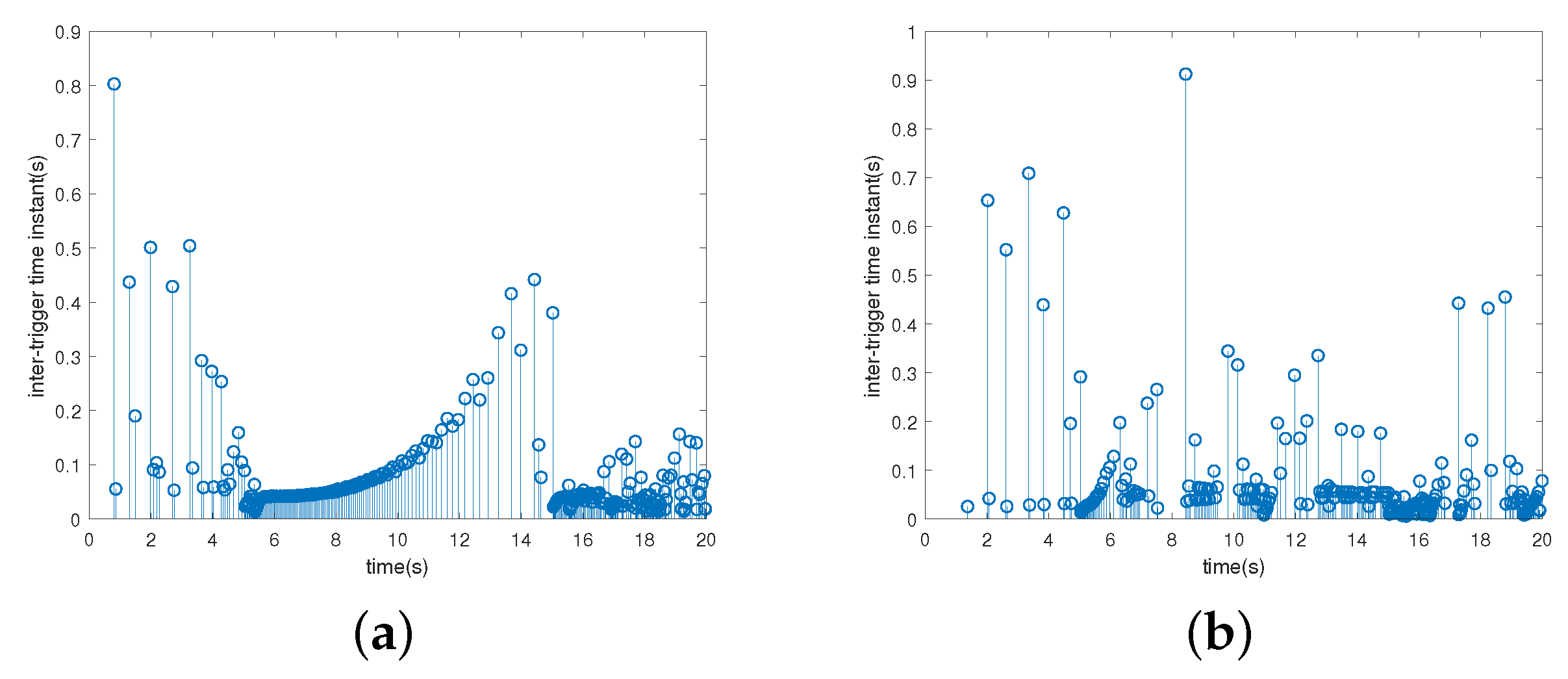
- The inter-MGs distributed control, where the information is transmitted through the inter-MGs communication network, is configured at the leader DG in each MG. It aims to achieve the cooperation among multiple MGs in the cluster. The self-triggered mechanism is introduced in the inter-MGs distributed control to reduce the inter-MGs communication burdens while achieving the frequency restoration and active power sharing of all leader DGs in finite-time.
- The intra-MG distributed control, where the information is transmitted through the intra-MG communication network, is configured at the follower DG. It aims to achieve the cooperation within each MG by driving the frequency and active power output ratio of follower DGs to those of leader DG, respectively. The event-triggered mechanism is introduced in the intra-MG distributed control to decrease the information amount transmitted in the intra-MG communication network.
- The hybrid-triggered mechanism based distributed secondary control integrates the self-triggered inter-MGs and event-triggered intra-MG distributed control, and it can realize the frequency restoration and active power sharing of the whole islanded MGs cluster. Furthermore, Zeno behavior is analyzed to be avoided, which demonstrates the rationality and practicability of the hybrid-triggered mechanism in practical islanded MGs cluster application.
2. Problem Formulation
2.1. Islanded MGs Cluster Configuration
2.2. Control Purposes
3. Main Result
3.1. Self-Triggered Mechanism Based Inter-MGs Distributed Secondary Control
3.2. Event-Triggered Mechanism Based Intra-MG Distributed Secondary Control
3.3. Distributed Hybrid-Triggered Secondary Control for Islanded MGs Cluster
4. Simulation
4.1. Case A: Robustness against Load Changes
4.2. Case B: MG Plug-and-Play Capability
5. Conclusions
Author Contributions
Funding
Conflicts of Interest
References
- Katiraei, F.; Iravani, M.R. Power management strategies for a microgrid with multiple distributed generation units. IEEE Trans. Power Syst. 2006, 21, 1821–1831. [Google Scholar] [CrossRef]
- Liu, S.; Liu, P.X.; Wang, X. Stochastic small-signal stability analysis of grid-connected photovoltaic systems. IEEE Trans. Ind. Electron. 2015, 63, 1027–1038. [Google Scholar] [CrossRef]
- Pogaku, N.; Prodanovic, M.; Green, T.C. Modeling, analysis and testing of autonomous operation of an inverter-based microgrid. IEEE Trans. Power Electron. 2007, 22, 613–625. [Google Scholar] [CrossRef]
- Atawi, I.E.; Kassem, A.M.; Zaid, S.A. Modeling, Management, and Control of an Autonomous Wind/Fuel Cell Micro-Grid System. Processes 2019, 7, 85. [Google Scholar] [CrossRef]
- Lai, J.; Lu, X.; Yu, X.; Monti, A. Cluster-oriented distributed cooperative control for multiple AC microgrids. IEEE Trans. Ind. Inf. 2019, 15, 5906–5918. [Google Scholar] [CrossRef]
- Liu, K.; Liu, T.; Tang, Z.; Hill, D.J. Distributed MPC-Based Frequency Control in Networked Microgrids With Voltage Constraints. IEEE Trans. Smart Grid 2019, 10, 6343–6354. [Google Scholar] [CrossRef]
- Du, Y.; Lu, X.; Wang, J.; Lukic, S. Distributed Secondary Control Strategy for Microgrid Operation with Dynamic Boundaries. IEEE Trans. Smart Grid 2019, 10, 5269–5282. [Google Scholar] [CrossRef]
- Yan, Y.; Shi, D.; Bian, D.; Huang, B.; Yi, Z.; Wang, Z. Small-Signal Stability Analysis and Performance Evaluation of Microgrids Under Distributed Control. IEEE Trans. Smart Grid 2019, 10, 4848–4858. [Google Scholar] [CrossRef]
- Lu, X.; Yu, X.; Lai, J.; Wang, Y.; Guerrero, J.M. A Novel Distributed Secondary Coordination Control Approach for Islanded Microgrids. IEEE Trans. Smart Grid 2018, 9, 2726–2740. [Google Scholar] [CrossRef]
- Zholbaryssov, M.; Dominguez-Garcia, A.D. Microgrid Distributed Frequency Control Over Time-Varying Communication Networks. In Proceedings of the 2018 IEEE Conference on Decision and Control (CDC), Miami Beach, FL, USA, 17–19 December 2018; pp. 5722–5727. [Google Scholar] [CrossRef]
- Lu, X.; Lai, J.; Yu, X.; Wang, Y.; Guerrero, J.M. Distributed coordination of islanded microgrid clusters using a two-layer intermittent communication network. IEEE Trans. Ind. Inf. 2017, 14, 3956–3969. [Google Scholar] [CrossRef]
- Maknouninejad, A.; Qu, Z.; Enslin, J.; Kutkut, N. Clustering and cooperative control of distributed generators for maintaining microgrid unified voltage profile and complex power control. In PES T&D 2012; IEEE: Piscataway, NJ, USA, 2012; pp. 1–8. [Google Scholar]
- Nutkani, I.U.; Loh, P.C.; Blaabjerg, F. Distributed operation of interlinked AC microgrids with dynamic active and reactive power tuning. IEEE Trans. Ind. Appl. 2013, 49, 2188–2196. [Google Scholar] [CrossRef]
- Lai, J.; Zhou, H.; Lu, X.; Yu, X.; Hu, W. Droop-based distributed cooperative control for microgrids with time-varying delays. IEEE Trans. Smart Grid 2016, 7, 1775–1789. [Google Scholar] [CrossRef]
- Yue, D.; Tian, E.; Han, Q.L. A Delay System Method for Designing Event-Triggered Controllers of Networked Control Systems. IEEE Trans. Autom. Control 2013, 58, 475–481. [Google Scholar] [CrossRef]
- Wang, X.; Lemmon, M. Event-Triggering in Distributed Networked Control Systems. IEEE Trans. Autom. Control 2011, 56, 586–601. [Google Scholar] [CrossRef]
- Seyboth, G.S.; Dimarogonas, D.V.; Johansson, K.H. Event-based broadcasting for multi-agent average consensus. Automatica 2013, 49, 245–252. [Google Scholar] [CrossRef]
- Almeida, J.; Silvestre, C.; Pascoal, A. Synchronization of multiagent systems using event-triggered and self-triggered broadcasts. IEEE Trans. Autom. Control 2017, 62, 4741–4746. [Google Scholar] [CrossRef]
- Ding, L.; Wang, L.Y.; Yin, G.; Zheng, W.X.; Han, Q. Distributed Energy Management for Smart Grids With an Event-Triggered Communication Scheme. IEEE Trans. Control Syst. Technol. 2018, 14, 1950–1961. [Google Scholar] [CrossRef]
- Chen, M.; Xiao, X.; Guerrero, J.M. Secondary Restoration Control of Islanded Microgrids With a Decentralized Event-Triggered Strategy. IEEE Trans. Ind. Inf. 2018, 14, 3870–3880. [Google Scholar] [CrossRef]
- Li, C.; Yu, X.; Yu, W.; Huang, T.; Liu, Z.W. Distributed event-triggered scheme for economic dispatch in smart grids. IEEE Trans. Ind. Inf. 2016, 12, 1775–1785. [Google Scholar] [CrossRef]
- Fan, Y.; Hu, G.; Egerstedt, M. Distributed reactive power sharing control for microgrids with event-triggered communication. IEEE Trans. Control Syst. Technol. 2016, 25, 118–128. [Google Scholar] [CrossRef]
- Xu, S.; Sun, H.; Zhao, B.; Yi, J.; Weng, S.; Chen, J.; Dou, C. Distributed Optimal Frequency Regulation for Multiple Distributed Power Generations with an Event-Triggered Communication Mechanism. Processes 2020, 8, 169. [Google Scholar] [CrossRef]
- Fan, Y.; Zhang, C.; Song, C. Sampling-based self-triggered coordination control for multi-agent systems with application to distributed generators. Int. J. Syst. Sci. 2018, 49, 3048–3062. [Google Scholar] [CrossRef]
- Tahir, M.; Mazumder, S.K. Self-triggered communication enabled control of distributed generation in microgrids. IEEE Trans. Ind. Inf. 2015, 11, 441–449. [Google Scholar] [CrossRef]
- Olfati-Saber, R.; Murray, R.M. Consensus problems in networks of agents with switching topology and time-delays. IEEE Trans. Autom. Control 2004, 49, 1520–1533. [Google Scholar] [CrossRef]
- Hong, Y.; Hu, J.; Gao, L. Tracking control for multi-agent consensus with an active leader and variable topology. Automatica 2006, 42, 1177–1182. [Google Scholar] [CrossRef]


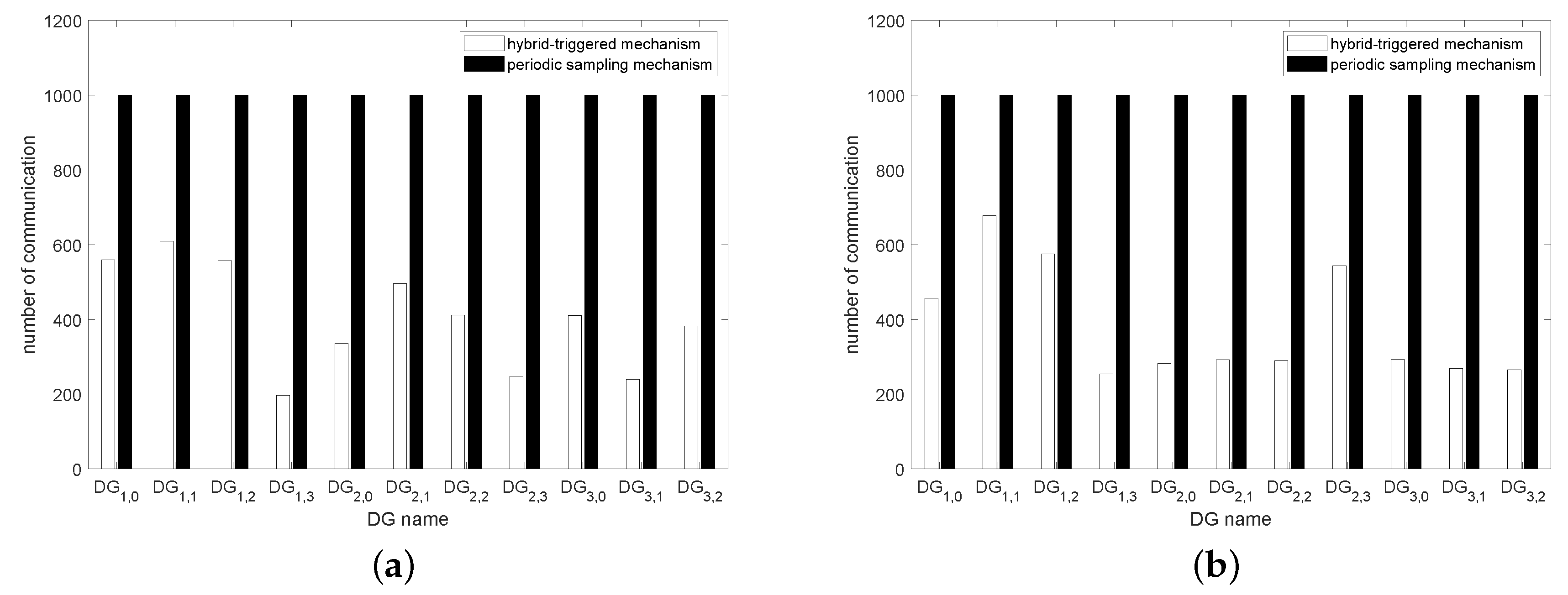
| HTM | 560 | 610 | 557 | 197 | 336 | 496 | 412 | 248 | 410 | 240 | 383 |
| PSM | 1000 | 1000 | 1000 | 1000 | 1000 | 1000 | 1000 | 1000 | 1000 | 1000 | 1000 |
| rate | 56.0% | 61.0% | 55.7% | 19.7% | 33.6% | 49.6% | 41.2% | 24.8% | 41.0% | 24.0% | 38.3% |
| HTM | 457 | 678 | 575 | 254 | 282 | 292 | 290 | 544 | 294 | 269 | 265 |
| PSM | 1000 | 1000 | 1000 | 1000 | 1000 | 1000 | 1000 | 1000 | 1000 | 1000 | 1000 |
| rate | 45.7% | 67.8% | 57.5% | 25.4% | 28.2% | 29.2% | 29.0% | 54.4% | 29.4% | 26.9% | 26.5% |
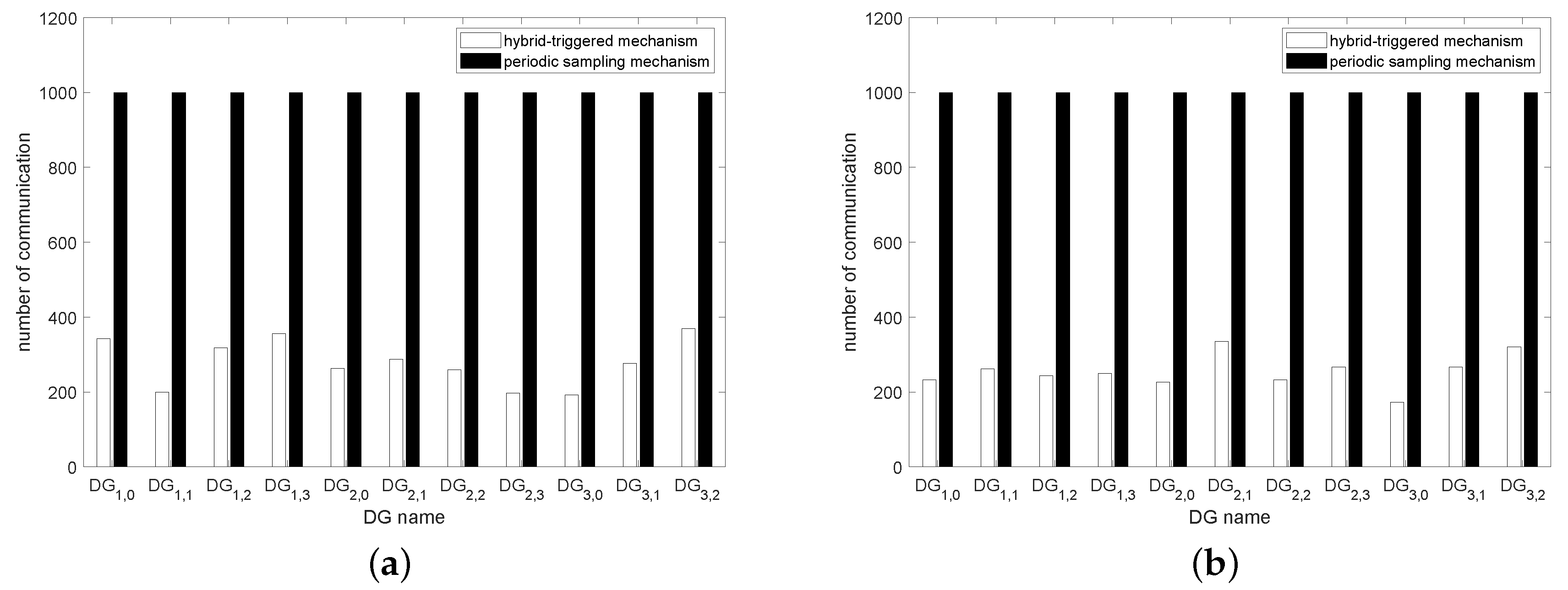
| HTM | 343 | 200 | 318 | 356 | 263 | 287 | 259 | 197 | 192 | 277 | 369 |
| PSM | 1000 | 1000 | 1000 | 1000 | 1000 | 1000 | 1000 | 1000 | 1000 | 1000 | 1000 |
| rate | 34.3% | 20.0% | 31.8% | 35.6% | 26.3% | 28.7% | 25.9% | 19.7% | 19.2% | 27.7% | 36.9% |
| HTM | 233 | 262 | 243 | 250 | 227 | 335 | 232 | 267 | 173 | 267 | 320 |
| PSM | 1000 | 1000 | 1000 | 1000 | 1000 | 1000 | 1000 | 1000 | 1000 | 1000 | 1000 |
| rate | 23.3% | 26.2% | 24.3% | 25.0% | 22.7% | 33.5% | 23.2% | 26.7% | 17.3% | 26.7% | 32.0% |
© 2020 by the authors. Licensee MDPI, Basel, Switzerland. This article is an open access article distributed under the terms and conditions of the Creative Commons Attribution (CC BY) license (http://creativecommons.org/licenses/by/4.0/).
Share and Cite
Weng, S.; Xue, Y.; Luo, J.; Li, Y. Distributed Secondary Control for Islanded Microgrids Cluster Based on Hybrid-Triggered Mechanisms. Processes 2020, 8, 370. https://doi.org/10.3390/pr8030370
Weng S, Xue Y, Luo J, Li Y. Distributed Secondary Control for Islanded Microgrids Cluster Based on Hybrid-Triggered Mechanisms. Processes. 2020; 8(3):370. https://doi.org/10.3390/pr8030370
Chicago/Turabian StyleWeng, Shengxuan, Yusheng Xue, Jianbo Luo, and Yanman Li. 2020. "Distributed Secondary Control for Islanded Microgrids Cluster Based on Hybrid-Triggered Mechanisms" Processes 8, no. 3: 370. https://doi.org/10.3390/pr8030370
APA StyleWeng, S., Xue, Y., Luo, J., & Li, Y. (2020). Distributed Secondary Control for Islanded Microgrids Cluster Based on Hybrid-Triggered Mechanisms. Processes, 8(3), 370. https://doi.org/10.3390/pr8030370