Article

A Visualization and Control Strategy for Dynamic Sustainability of Chemical Processes

by
Shuyun Li
1,
Gerardo J. Ruiz-Mercado
2 and
Fernando V. Lima
1,*
1
Department of Chemical and Biomedical Engineering, West Virginia University, Morgantown, WV 26506, USA
2
Office of Research and Development, Center for Environmental Solutions and Emergency Response, U.S. Environmental Protection Agency, Cincinnati, OH 45268, USA
*
Author to whom correspondence should be addressed.
Processes 2020, 8(3), 310; https://doi.org/10.3390/pr8030310
Submission received: 11 January 2020 / Revised: 10 February 2020 / Accepted: 18 February 2020 / Published: 7 March 2020
(This article belongs to the Special Issue Bioenergy Systems, Material Management, and Sustainability)

Abstract

:
Our societal needs for greener, economically viable products and processes have grown given the adverse environmental impact and unsustainable development caused by human activities, including chemical releases, exposure, and impacts. To make chemical processes safer and more sustainable, a novel sustainability-oriented control strategy is developed in this work. This strategy enables the incorporation of online sustainability assessment and process control with sustainability constraints into chemical process operations. Specifically, U.S. Environmental Protection Agency (EPA)’s GREENSCOPE (Gauging Reaction Effectiveness for the ENvironmental Sustainability of Chemistries with a multi-Objective Process Evaluator) tool is used for sustainability assessment and environmental release minimization of chemical processes. The multivariable GREENSCOPE indicators in real time can be represented using a novel visualization method with dynamic radar plots. The analysis of the process dynamic behavior in terms of sustainability performance provides means of defining sustainability constraints for the control strategy to improve process sustainability aspects with lower scores. For the control task, Biologically Inspired Optimal Control Strategy (BIO-CS) is implemented with sustainability constraints so that the control actions can be calculated considering the sustainability performance. This work leads to a significant step forward towards augmenting the capability of process control to meet future demands on multiple control objectives (e.g., economic, environmental, and safety related). The effectiveness of the proposed framework is illustrated via two case studies associated with a fermentation system. The results show that the proposed control strategy can effectively drive the system to the desired setpoints while meeting a preset sustainability constraint and improving the transient sustainability performance by up to 16.86% in terms of selected GREENSCOPE indicators.

1. Introduction

In recent years, integrating sustainability into the decision-making process in the chemical industry has become increasingly important. This fact can be attributed to the growing environmental and social awareness that makes consumers and stakeholders care about not only product quality and cost but also products and processes that minimize the environmental impact and that conserve natural resources. Fortunately, in the last decade, significant progress has been made in recognizing and understanding the challenges in sustainable development and sustainability evaluation of a specific process/product. In particular, the advances in the development of sustainability tools help the engineers and scientists with designing and improving the chemical processes in terms of sustainability. The available sustainability assessment tools can be mainly grouped in two main categories: metric-oriented methods [1,2] and life cycle assessment (LCA) [3]. For the metric-oriented methods, the focus is on translating the holistic concept of sustainability into well-defined indicators in economic, environmental, and social aspects within predefined boundaries. For example, several key sustainability indices developed by the American Institute of Chemical Engineers (AIChE) [4,5] and UK Institution of Chemical Engineering [6] include environmental impact, safety, product stewardship, innovation, and societal measures. Once quantified, such developed indicators are typically aggregated based on weights defined by decision makers. A recent tool developed by the US Environmental Protection Agency (EPA), GREENSCOPE (Gauging Reaction Effectiveness for the ENvironmental Sustainability of Chemistries with a multi-Objective Process Evaluator) [7,8,9], proposed about 140 indicators in environmental, energy, efficiency, and economic aspects to evaluate a product or process in terms of sustainability. Although many of these indicators have boundaries that do not consider the full life cycle, they provide comprehensive assessment of a process operation and can be normalized by a functional unit (e.g., production rate or total profit). LCA methods intend to quantify the environmental impact of a selected product or process within its life cycle “from cradle to grave.” Both method categories are useful and complementary for sustainability assessment. Previous work has reported the progress on developing a comprehensive sustainability assessment tool for defining life cycle inventory (LCI) and sustainability indicators [10]. In this work, the focus will be on applying sustainability indicators to assess process-transient operations.
Given the available sustainability assessment tools and methods, many contributions have been made with regards to integrating sustainability into supply chain, process design, and multi-objective optimization at different scales. For example, literature on sustainable supply chain management showed the progress of taking into consideration environmental and social impacts by integrating sustainability into the developed framework [11,12]. Along the same lines, sustainable process design and multi-objective optimization (MOO) methods have been demonstrated on a variety of applications at different scales, from molecular chemistry [13] to ecosystems [14]. However, studies concerning the sustainability of real-time process operations are still at the early stages despite the fact that control techniques and theory have evolved significantly in the last two decades [15]. For instance, advanced nonlinear model predictive control (NMPC) techniques can control nonlinear, large-scale chemical processes effectively and safely even in the presence of disturbances and uncertainties. In particular, advanced features of control techniques have been under development in academia, such as economic MPC [16], stochastic MPC [17], and safeness-index based MPC [18]. However, to this day, the primary focus of the process control area is to improve the economic or safety-related performance of the process, regardless of environmental and social costs. There are only a few reported studies on process operations employing sustainability-oriented control strategies. A recent review [19] described the challenges of incorporating sustainability goals into process control and stated that sustainability will be a major driver for controller development in the future due to the pressure of taking the sustainable principles into account during process operations. In Reference [20], a method was proposed to integrate deterministic dynamic optimization with optimal control for addressing the sustainability of a batch reactor. Another application of deterministic optimal control strategies was reported to improve energy efficiency in manufacturing processes [21]. In these two studies, only utilities-related environmental impacts were considered. As described in the literature [19], the scarcity of studies on sustainable process control can be attributed to the lack of strategies that can effectively integrate process sustainability aspects into the advanced controller framework, considering the conflicting nature of sustainability indicators (e.g., economic vs. environmental aspects).
As a step forward to contributing to the field of process control for sustainability, in this article, the previously developed framework [22] that integrated an advanced process control strategy with sustainability assessment tools is enhanced. In the previous work, process control was employed to take the system to different operating conditions. Then, an offline sustainability assessment was used to comprehensively evaluate the reached steady-state alternatives. An improved steady-state sustainability performance was then obtained after the controller implementation, without considering the process performance during transience. In the proposed framework in this article, the dynamic sustainability assessment during transience is incorporated using a novel visualization method with dynamic radar plots. With the better understanding of the process dynamic behavior in economic, environmental, and social aspects, sustainability constraints can be defined and directly embedded into the control strategy so that the control action can be calculated considering the system sustainability performance. The effectiveness of the proposed framework is demonstrated via the case study of a fermentation process for bioethanol production. The outline of the rest of this paper is as follows: Section 2 presents the background on the fermentation process model and the sustainability assessment tools. In Section 3, the proposed sustainability-oriented framework and the advanced controller for sustainability are described. Section 4 introduces the visualization method for dynamic sustainability performance with an example. In Section 5, the proposed framework is applied to the fermentation process to demonstrate the controller’s effectiveness. Finally, the paper is closed with conclusions and considerations for future work.

2. Background

2.1. Fermentation Process

Ethanol derived from renewable resources provides a more sustainable way to decrease greenhouse gas emissions as well as the dependence on fossil fuels. Fermentation processes, as one of the traditional technologies, are widely used in the industry for ethanol production from corn and beets. Ethanol fermentation process is carried out with living microorganisms, including bacteria and yeast. For example, the yeast Saccharomyces cerevisiae is one of the most popular in current fermentation industry due to its tolerance to low pH and high ethanol concentration, while the bacterium Zymomonas mobilis is known for the higher product yield from glucose/sucrose. In this work, a continuous fermentation process with Zymomonas mobilis is considered for ethanol production from glucose solution. Specifically, a homogeneous, perfectly mixed continuous stirred tank reactor (CSTR) is used for ethanol production. This reactor is equipped with an ethanol-selective removal membrane and a cooling jacket for temperature control. The schematic of the ethanol fermenter studied in this work is shown in Figure 1. With the in situ ethanol-removal membrane, ethanol can be removed to prevent end-product inhibition and to improve the productivity and efficiency of the fermentation process.
These process dynamics have been studied in a previous work [22], including the challenging characteristics of steady-state multiplicity and oscillatory behavior. To accurately describe this process, a mathematical model that includes mass and energy balances is developed. This model covers the mass balances of the concentrations of key component ( C e ), substrate ( C S ), biomass ( C X ), product from fermenter side ( C P ), and product from membrane side ( C P M ), as well as energy balances of fermenter temperature ( T r ) and cooling water temperature ( T j ). Overall, a set of seven ordinary differential equations (ODEs) for mass and energy balances and two algebraic equations for inlet dilution rate ( D i n ) and membrane dilution rate ( D m , i n ), is expressed by the following equations:
d C e d t = ( k 1 k 2 C P + k 3 C p 2 ) C S C e ( K S + C S ) + D i n C e , 0 D o u t C e
d C S d t = ( P Y s x ) · f ( T ) · C S C e ( K S + C S ) m s C X + D i n C S , 0 D o u t C S
d C X d t = P · f ( T ) · C S C e K S + C S + D i n C X , 0 D o u t C X
d C P d t = ( P Y p x ) · f ( T ) · C S C e ( K S + C S ) + m p C X + D i n C P , 0 D o u t C P ( α V F ) ( C P C P M )
d C P M d t = ( α V M ) ( C P C P M ) + D m , i n C P M , 0 D m , o u t C P M
d T r d t = D i n ( T i n T r ) + r S · Δ H ρ r · C p , r K T A T · ( T r T j ) V F ρ r · C p , r
d T j d t = D j ( T w , i n T j ) + K T A T · ( T r T j ) V j ρ w · C p , w
D o u t = D i n α · ( C P C P M ) V F · ρ r
D m , o u t = D m , i n + α · ( C P C P M ) V M · ρ r
in which the variable descriptions are available in the Nomenclature section. For more detailed information on model development, please refer to Reference [22]. Table A1 provides the parameter values of the model and the initial operating conditions used in this Zymomonas mobilis fermentation process.

2.2. Sustainability Assessment Tool

Many sustainability tools have been developed for process performance assessment. However, most of the available sustainability tools are not comprehensive enough for evaluating the operating performance of chemical processes. A suitable tool should be able to meet the following requirements: (1) quantify the process impact on social, environmental, and economic pillars of sustainability; (2) describe the assessment results in a transparent and standard way; and (3) extend traditional sustainability analysis to assess process dynamic performance. GREENSCOPE, as a sustainability evaluation and design tool, can provide a holistic sustainability performance analysis for chemical processes that meets these requirements and helps the process designers and decision-makers with comparing multiple processes or locating areas for analyzing the optimal trade-offs in terms of sustainability.
To quantitatively describe process sustainability performance, GREENSCOPE employs a set of sustainability indicators in four areas: efficiency (26 indicators), economics (33 indicators), environment (66 indicators), and energy (14 indicators). Specifically, efficiency indicators describe the process performance in terms of mass transfer operations by connecting material input and output with the desired product. Economic indicators are based on the profitability criteria for a commercial chemical process considering raw material cost, utility cost, capital, and labor costs. For the ~66 environmental indicators, environmental, health, and safety (EHS) potential risks are measured according to the involved input materials, operating conditions, and potential impact of releases. For the energy indicators, two different thermodynamic methods (energy and exergy) have been used to characterize the thermodynamic efficiencies of the process. More detailed information on the indicator definitions, calculations, and applications are available in the literature [7,8,9]. In GREENSCOPE, all the sustainability indicators are described by dimensionless scores between the worst- and best-case using Equation (10):
P e r c e n t   S c o r e   ( P S ) =   | A c t u a l W o r s t | | B e s t W o r s t | × 100 %
in which the best case represents 100% sustainable while the worst case 0% sustainable for each indicator. The best and worst case values of the selected sustainability indicators in this work are either based on GREENSCOPE default values or obtained following GREENSCOPE guidelines. Some guidelines on how to select the best/worst case values for GREENSCOPE can be found in the literature [7,8,9,23]. For example, the best-case value for the Reaction Yield (RY) indicator is 1, while the worst-case value is always 0 for all the reactions. Other indicators without absolute values can have their best- and worst-case values determined based on the amount and composition from the process input and output streams (e.g., waste release, production rate, and utility consumption). The normalized indicators offer some advantages for applying GREENSCOPE to different scenarios. Moreover, the dimensionless indicators can be lumped or aggregated for process optimization or control studies based on a user-selected weighting method. Finally, the dimensionless indicator scores enable visualization of the multidimensional sustainability performance using radar plots. A novel visualization technique for analyzing process sustainability performance during transience is described in Section 4.

3. Process Control for Sustainable Process Operation

3.1. Integrated Control Strategy for Sustainability

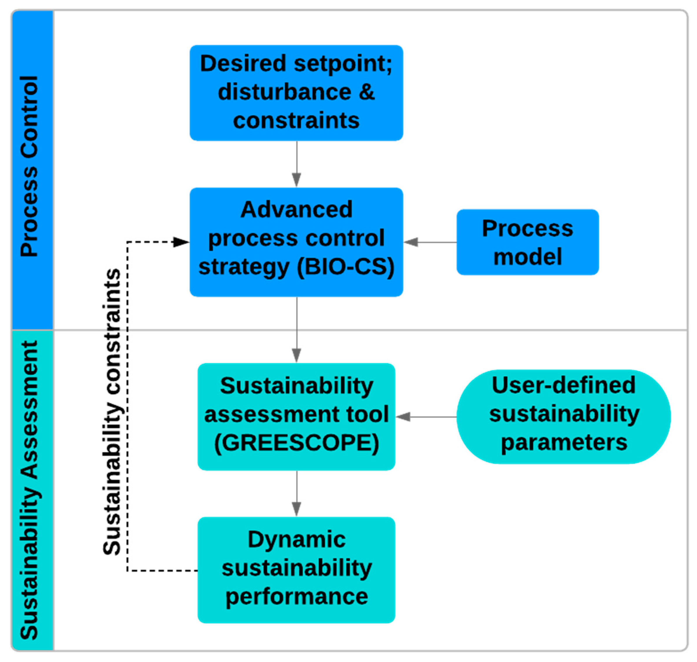
The proposed control framework in this paper is built as an integrated approach that includes nonlinear process control and online sustainability assessment, as shown in Figure 2. The role of the online sustainability assessment part is to monitor the impact of the control action in terms of sustainability and to provide information to the controller on the thresholds for the selected sustainability indicators. Sustainability concerns/policies can then be successfully translated to process control actions to improve the process sustainable performance.

3.2. BIO-CS (Biologically Inspired Optimal Control Strategy) Controller

An in-house control toolbox for BIO-CS [24] developed in MATLAB (available upon request) is implemented to address the control task. BIO-CS is an optimal control approach that combines the ants’ rule of pursuit idea with multiagent concepts. The resulting agent-based control framework allows each follower agent to update its path toward the set point based on the leader agent’s feasible trajectory. As the number of agents progresses, the trajectories converge to an optimal solution. The developed algorithm employs gradient-based optimal control solvers (e.g., dynopt optimization toolbox [25]) in the toolbox for solving the constrained/unconstrained nonlinear optimization problems. The effectiveness of the BIO-CS control algorithm has been illustrated via applications associated with a fermentation processes [26], a hybrid energy system [27], and a coal-fired power plant [28]. In this work, the capability of integrating sustainability into the BIO-CS formulation is explored. The sustainability-oriented BIO-CS is formulated as follows:
min u ( t ) J =   τ i τ s ( | | y ( τ ) y s p | | w 1 2 + | | u ( τ ) u ( τ ) | | w 2 2 ) d τ
s . t .   x ˙ ( t ) = f ( u ( t ) ,   x ( t ) ,   y ( t ) ,   p ,   t )
S I i S I t h  
  x ( t ) [ x ( t ) l b , x ( t ) u b ]
  u ( t ) [ u ( t ) l b , u ( t ) u b ]
in which u ( t ) , x ( t ) , and y ( t ) are the input, state, and output variables, respectively, and τ stands for time. The optimal input trajectory of the control problem is u ( t ) , which is calculated over the sampling time t [ τ i , τ s ) . This calculation is subject to the process model, f ( · ) ; sustainability constraints specified by a sustainability index, S I i ; and boundary constraints on u ( t ) and x ( t ) . Please refer to publications [24,25,26,27,28] for the detailed algorithm and applications of BIO-CS.

4. Visualization of Dynamic Sustainability Performance

4.1. Visualization Approach

Understanding the dynamic behavior of sustainable systems and controlling the process to meet the sustainability goals are critical tasks in the sustainability field. However, research in this direction is scarce. This fact can be attributed to the complex and integrated nature of the resulting problems when sustainability is incorporated into chemical process operations at different time and space scales. For example, sustainability requires the expansion of the traditional energy, economic, and product quality-focus to consider multiple objectives (e.g., environmental, economic, and social objectives). Despite these challenges, it is expected that sustainability will be a major driver for process systems engineering (PSE) to advance the capability of future chemical processes to deal with multiple control objectives while balancing conflicting objectives. Before moving to the implementation of the proposed framework, in this subsection, the proposed approach to monitor the process sustainability performance during transience is introduced so that the characteristics of dynamic sustainability performance of the process can be analyzed.
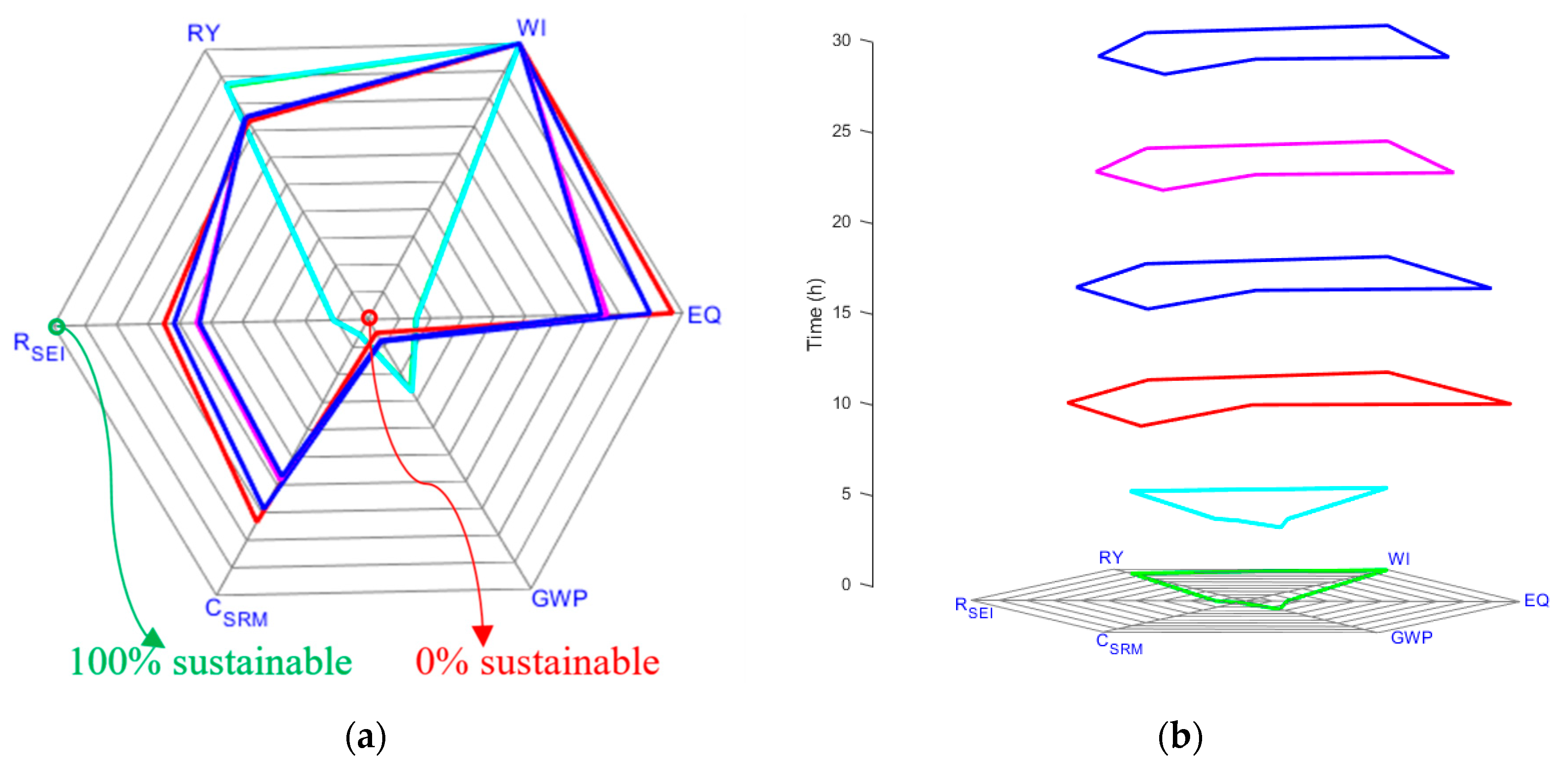
Here, process dynamics are referred to the essential relationships among different process variables (e.g., temperature, pressure, and concentration), while dynamic sustainability performance focuses on the understanding of the dynamic nature of the system from the sustainability perspective (e.g., in terms of sustainability indicators). For example, the fermentation process can be operated with the fermenter dilution rate ( D i n ), membrane dilution rate ( D m , i n ), and cooling water flow rate ( D j ) fixed at 0.5 h−1, 0.1 h−1, and 0.1 h−1, respectively. The dynamic sustainability performance of the process can be represented by selected GREENSCOPE indicators, such as Reaction Yield (RY), Water Intensity (WI), Environmental Quotient (EQ), Global Warming Potential (GWP), Specific Raw Material Cost (CSRM), and Specific Energy Intensity (RSEI) (refer to Table A2 in Appendix A for indicator definitions and details). The obtained GREENSCOPE indicator scores translate the process data into sustainability information for process monitoring and analysis during real-time operation. In this article, a time-explicit radar plotting technique is developed for displaying the multivariate sustainability information as depicted in Figure 3. In this approach, as shown in Figure 3a, each radar plot (or polygon) represents the selected six sustainability indicators with specific score values. According to the definition of a sustainability indicator score, the center represents 0% sustainable while the outside edge is 100% sustainable. Thus, a wider polygon means better performance in terms of sustainability. Then, visualization of sustainability performance along the time dimension can be accomplished by stacking multiple polygons on top of one another on the time axis, as shown in Figure 3b. The developed plotting method provides an efficient and intuitive way of presenting high-dimensional time-explicit sustainability performance. However, with the indicator numbers and time horizon increasing, it is hard to identify whether the operation is moving towards a more sustainable area especially when some indicators selected are conflicting. To better balance the tradeoff between conflicting indicators as well as to help with the decision-making step, a lumped sustainability index ( S I ) is defined for combining indicators with user-defined weighting factors. An average sustainability index ( S I ¯ ) can then be derived from the calculated S I values for analyzing or measuring the performance during any specific time interval. The definitions of these indices are shown below in Equations (12) and (13).
S u s t a i n a b i l i t y   I n d e x   ( S I ( t ) ) =   w i · P S i ( t ) w i · P S m a x ,   i
A v e r a g e   S u s t a i n a b i l i t y   I n d e x   ( S I ¯ ) =   t 0 t f S I ( t ) ( t f t 0 )
where w i , P S m a x , i , t 0 , and t f are the weighting factors and maximum percent score ( P S ) for the specific indicator i as well as the initial and final time intervals. Note that different weights can be assigned to selected indicators depending on user preferences or the application. A larger number for the weight means higher impact of the indicator on the overall sustainability performance. In this work, equal weights for the selected six sustainability indicators have been used throughout this study.

4.2. Open-Loop Simulation Example

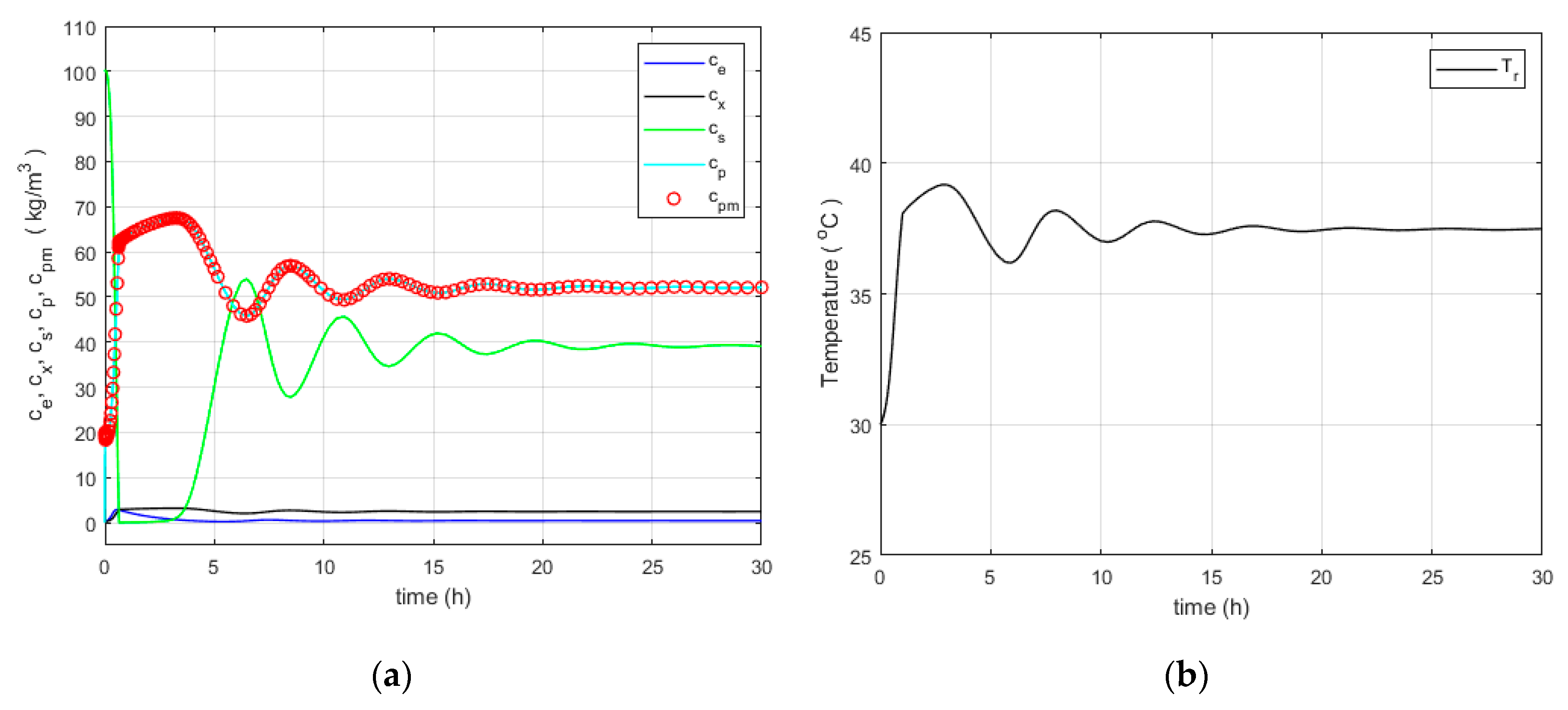
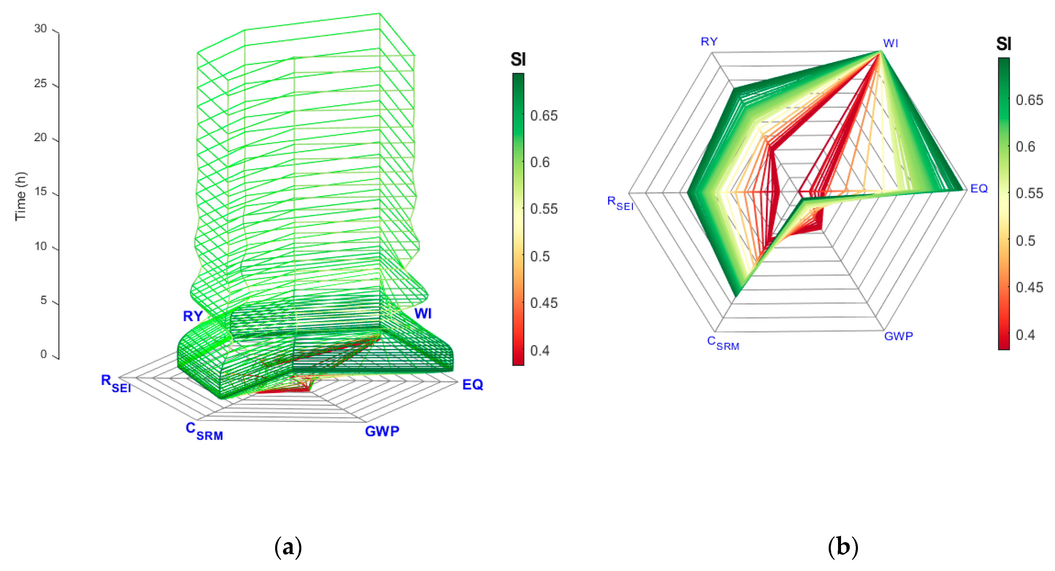
The process dynamics have a direct relationship with the dynamic sustainability performance of the process. Here, open-loop simulation results of the fermentation process are used to illustrate the effectiveness of the proposed dynamic sustainability visualization approach. Figure 4 shows the concentration profiles of the key component ( C e ), biomass ( C X ), substrate ( C S ), product in the fermenter ( C P ), and membrane sides ( C P M ), as well as fermenter temperature profile ( T r ) with the predefined operating conditions. As reported in the literature [22], the open-loop fermentation process exhibits oscillatory dynamic behavior. From the sustainability perspective, the six indicators mentioned above have been selected for evaluating the fermentation process in terms of efficiency, environmental, energy, and economic aspects and for identifying how the overall performance of the process can be improved in terms of sustainability. As shown in Figure 5, most indicators (except WI) follow the trends in the process oscillations shown in Figure 4. This can be explained by the fact that the dilution rates of D i n , D m , i n , and D j that are associated with WI are kept constant for the open-loop simulation and that the other indicators, such as RY, EQ, GWP, CSRM, and RSEI, are strongly related to the process dynamics. Fermentation involves two types of reactions: one is microbial growth reaction, and the other is the metabolite reaction for ethanol production. From the process dynamics in Figure 4a, it is clearly shown four distinguished process phases, at 0–1 h, 1–5 h, 5–18 h, and 18–30 h. For the time zone of 0–1 h, the substrate is mostly consumed for biomass and key component formation and the yield for ethanol is relatively low. Hence, process performance in terms of sustainability for this region is shown as red in Figure 5, which means less sustainable. This color scheme is defined according to the S I value for every time step. It is interesting to note that the most sustainable part of the simulation occurs during the transient stage of 1–5 h, which corresponds to the highest average reaction yield. During 5–18 h, strong oscillations start due to ethanol inhibition and the SI values start to decrease, which is reflected by a gradually changing green color along the time axis in Figure 5a. After 18 h, the system is prone to steady state with light green sustainability status, as shown in Figure 5. Through a deeper analysis of the dynamic sustainability performance, note that EQ, CSRM, RSEI, and overall sustainability performance improve with the higher RY while GWP drops with RY increasing. Such monitoring approach can thus help the design and implementation of the controller for keeping the system within a desired sustainable operating range.

5. Closed-Loop Simulation Results and Discussions

Two case studies are presented here to evaluate the effectiveness of the novel sustainable process control framework. The first case with a fixed D i n value of 0.1 h−1 is chosen to illustrate the application of the sustainability-oriented control strategy to improve the process sustainability performance. Specifically, the dynamic sustainability performance visualization approach is used to analyze how places with lower sustainability performance can be improved by adding sustainability constraints to the controller. The second case study shows the framework performance for a more challenging case with a higher D i n of 0.5 h−1, which corresponds to a higher volumetric productivity in the fermenter. For all simulations, the parameter values in Table A1 are kept constant.

5.1. Case 1

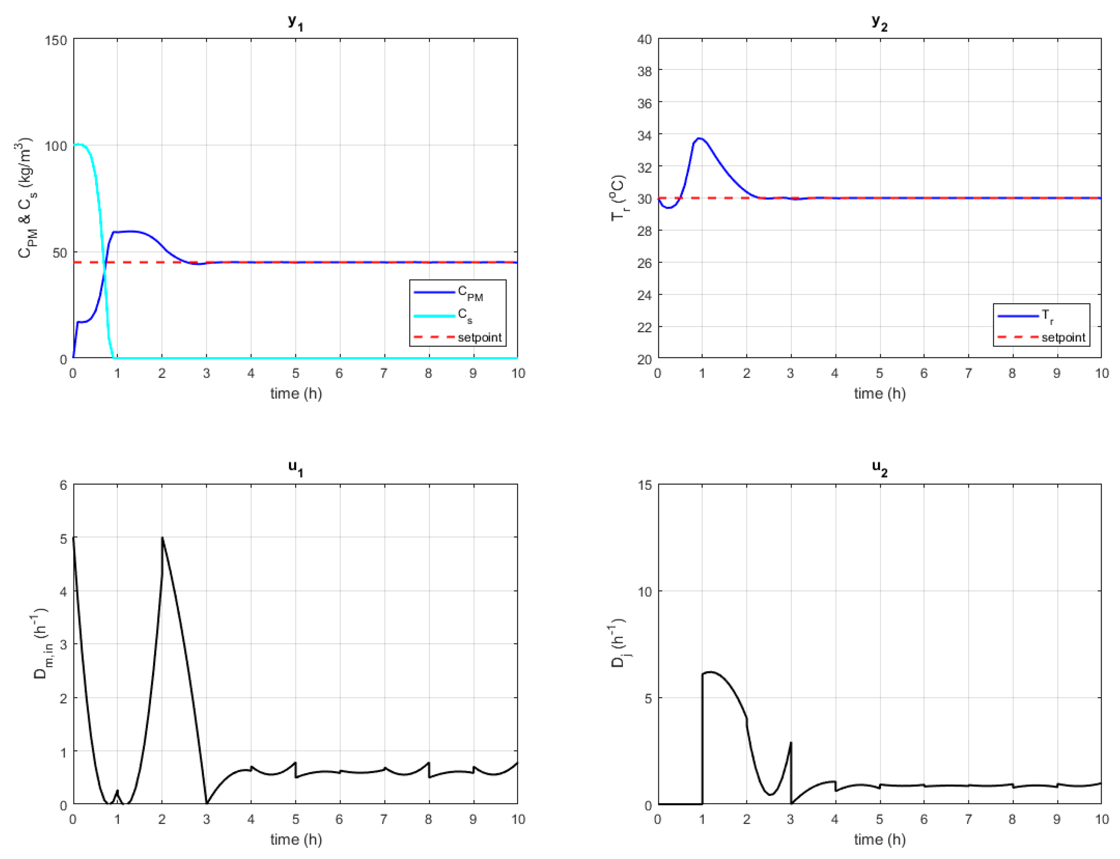
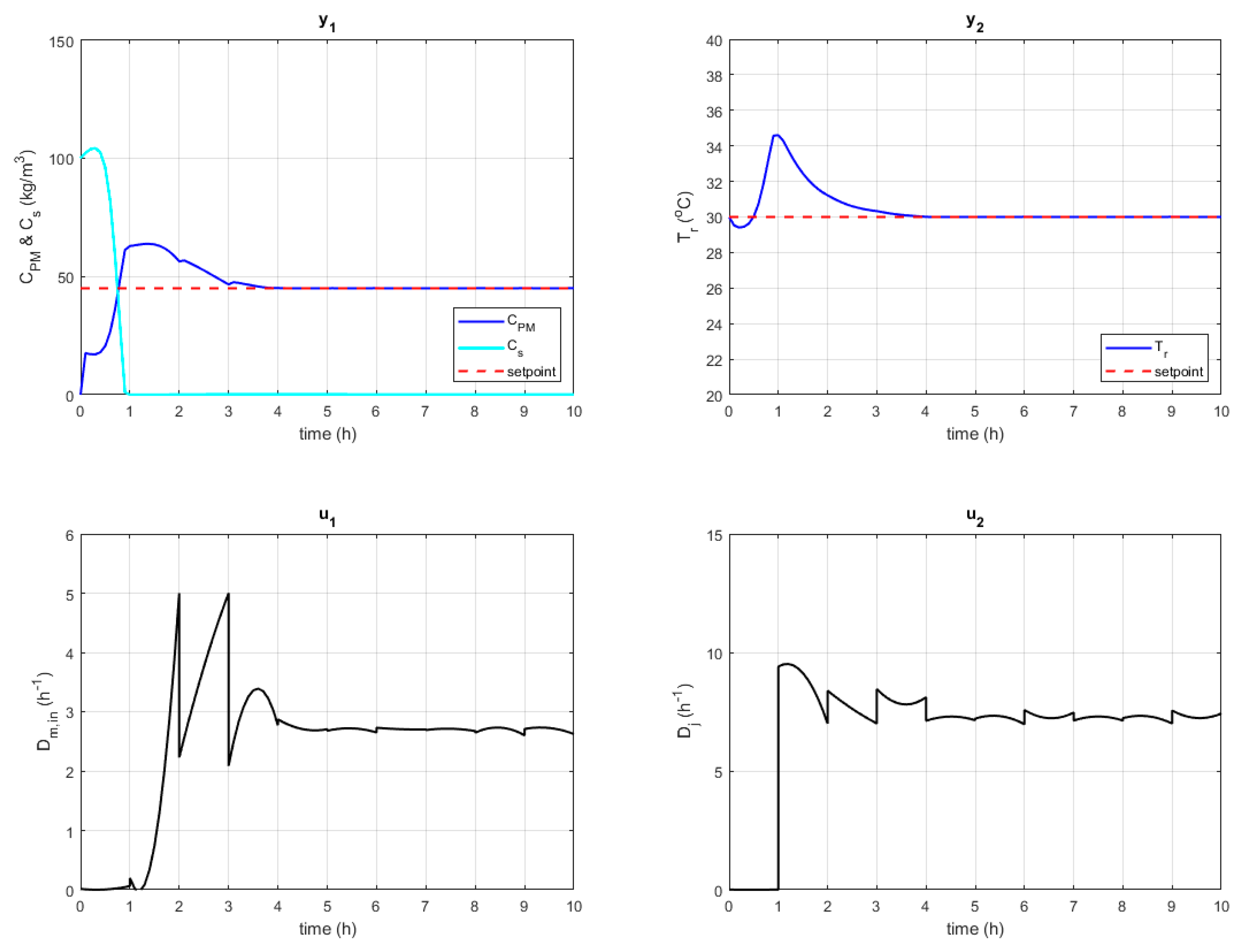
The effectiveness of the sustainability-oriented control strategy is first demonstrated using the fermentation process for a setpoint tracking study. In this case study, the optimal setpoints for C P M and T r are set to 48 kg/m3 and 30 °C, respectively, based on our previous studies [22,25]. The objective function of the controller is to minimize the difference between the values of the controlled variables, C P M and T r , with respect to their setpoints by optimizing the input variable ( D m , i n and D j ) trajectories, as shown in Equation (11a). Figure 6 depicts the closed-loop simulation results obtained for the output and input profiles. Note in this figure that, with the implementation of the proposed BIO-CS, the oscillations observed in the open-loop simulations are eliminated completely and the system reached the desired setpoints in ~3.5 h. Literature results [22] have shown that the steady state obtained here using the controller is more sustainable than the open-loop result. The proposed control strategy in this paper takes a step forward towards analyzing the sustainability performance along the path from the initial starting point (e.g., during start-up) to the desired steady state so that sustainability constraints can be defined and added to the controller design. As shown in Figure 7a, three distinguished regions in terms of sustainability performance characteristics can be observed at 0–0.8 h, 0.8–2 h, and 2–10 h. The time zone of 0–0.8 h (reddish zone with S I ¯ of ~0.78) is the start-up, which involves the conversion of substrate to ethanol as well as biomass cell reaction. The relatively low S I for this phase can be explained by the low efficiency of the fermentation process at the beginning, and biomass and key component are not growing enough for completely converting substrate into product. During 0.8–2 h, the overall sustainability performance first improves for a short time and then decreases. This can be attributed to the fact that the reaction yield or efficiency reached the highest level at 1 h and, then, the water usage starts to increase from 1 to 2 h as shown in Figure 6. Note that the WI indicator performance is directly associated with the profiles of the manipulated variables while EQ, GWP, CSRM, and RSEI are more prone to changes to RY. After 2 h, the main variables of the system reach the steady state, and thus, the sustainability performance is kept the same with S I ¯ of ~0.84. By further analyzing the sustainability performance, it is found that 0.8–2 h has relatively low S I ¯ at 0.77, which can be attributed to the lowest sustainability indicator of WI (lowest value of 58%). In order to make sure the WI score is above a certain threshold during transience, a nonlinear sustainability constraint related to the WI score is added to the BIO-CS controller as follows:
D i n · V f + D m , i n · V m + D j · V J ( WI u b WI l b ) × m ˙ p r o d u c t > 0.7
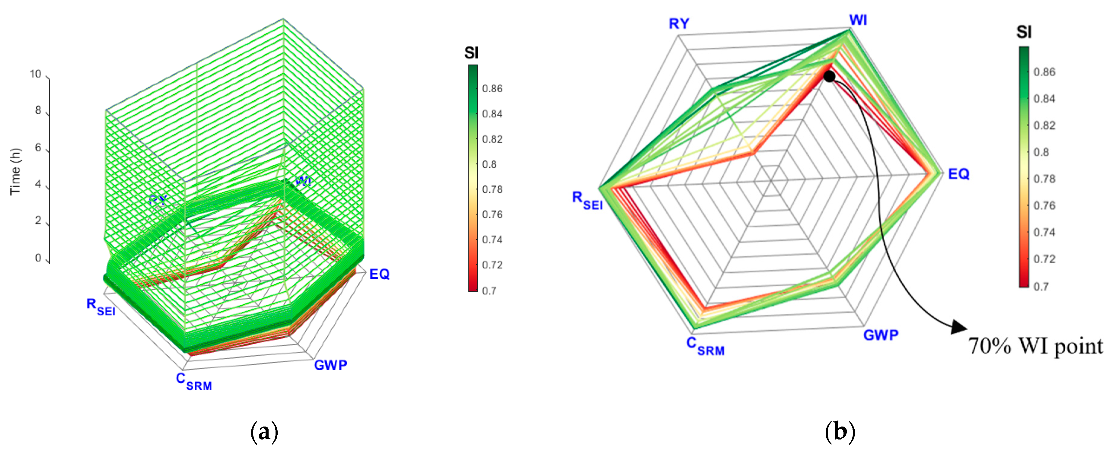
in which the sum of the terms in the numerator corresponds to the total water usage in the system and WI u b , WI l b , and m ˙ p r o d u c t represent the upper and lower boundaries for WI as well as production rate, respectively. The BIO-CS solver implemented can handle such nonlinear constraints effectively. Figure 8 and Figure 9 show the input and output profiles of the fermentation process and the dynamic sustainability performance, respectively, after the implementation of a WI constraint (WI > 70%). It is shown in Figure 9 that the BIO-CS controller with the sustainability constraint can successfully drive the system to the setpoints within a more sustainable range for water use while meeting the constraint. During 0.8–2 h, the sustainability performance with S I ¯ of 0.84 increases by 9.65% when compared to the scenario without the constraint ( S I ¯ of 0.77). Also, the water consumption during this transient time (0.8–2 h) dropped by 49.71%, from 0.0032 to 0.0016 m3/kg product (considering only the water consumption in the reactor). To clearly show the comparison in terms of the sustainability performance for the cases with/without the added sustainability constraint, Figure 10 shows all the sustainability indicators at three representative time points: 1.8 h, 2.1 h, and 10 h. Note that the constrained scenario changes the other sustainability indicators slightly during transient time (during 0–3 h) but that the final steady states are the same due to the same setpoints used for both scenarios. By comparing the inputs profiles in Figure 6 and Figure 8, it is found that BIO-CS optimizes the input profiles of D m , i n and   D j to avoid increasing these two variables simultaneously, thus optimizing the WI score. It is worth mentioning that the sustainability constrained problem slightly decreases the controller performance in terms of smoothness of the input profiles and time to reach steady state. A more advanced dynamic operability study [29] could be further investigated in the future for locating feasible sustainable ranges for process control improvements.

5.2. Case 2

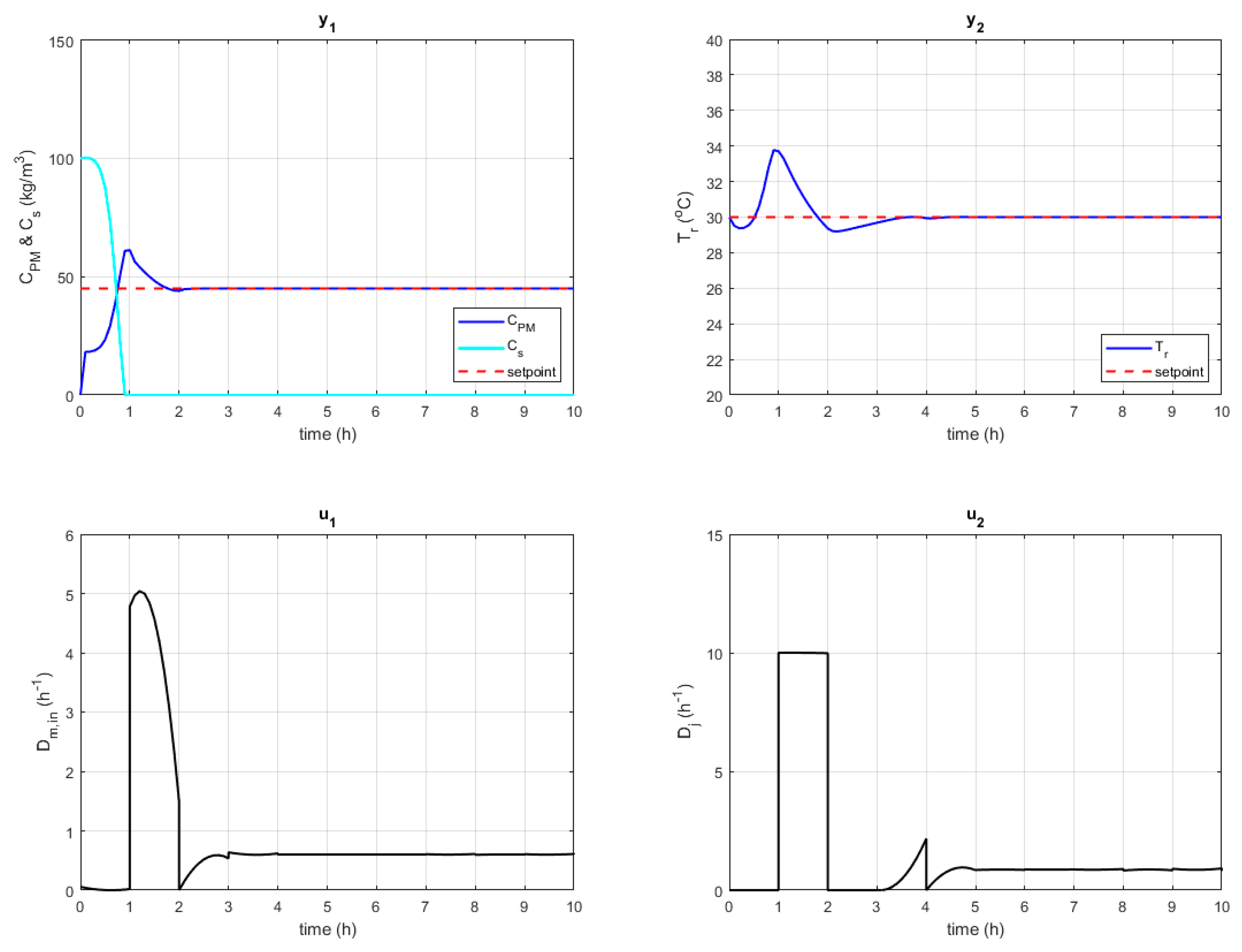
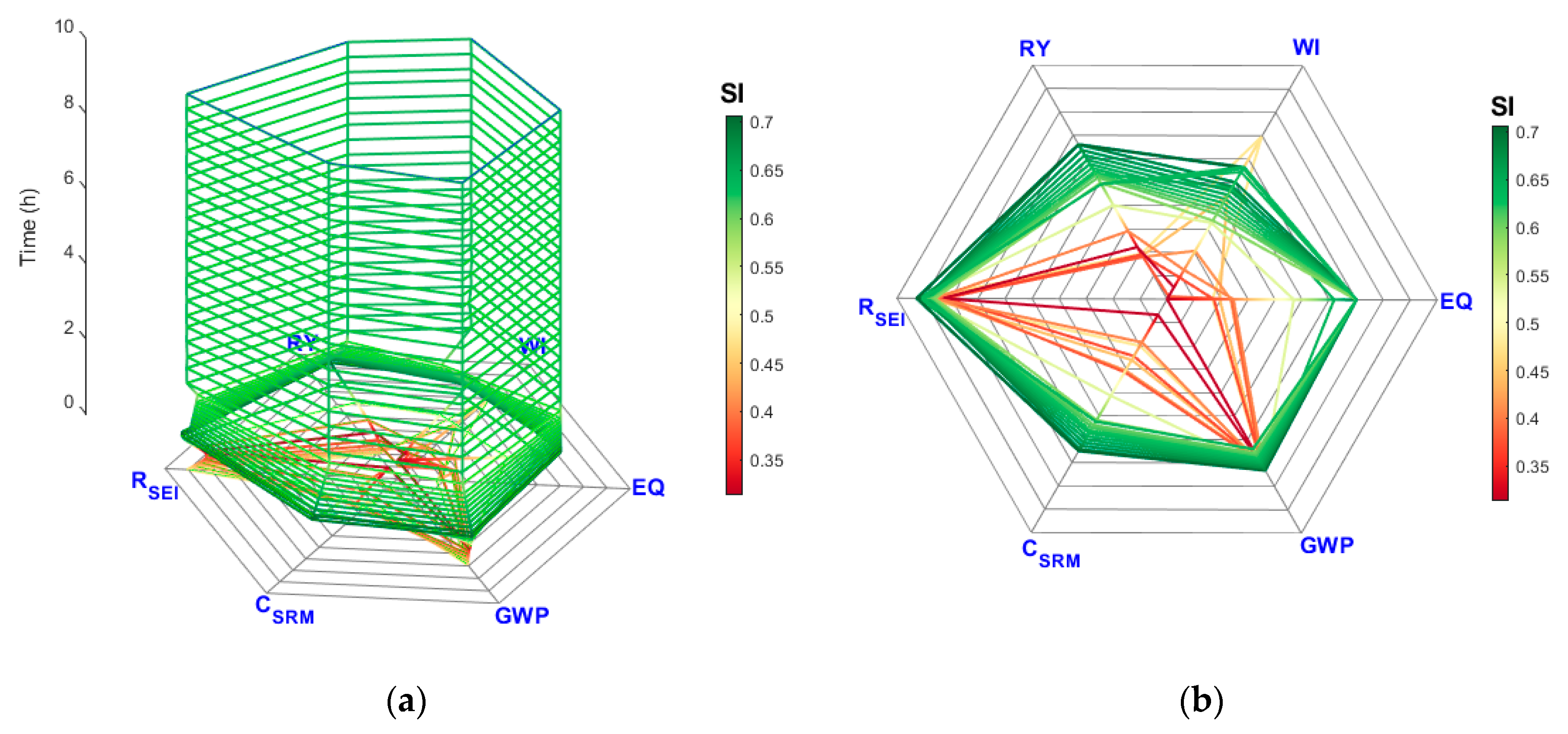
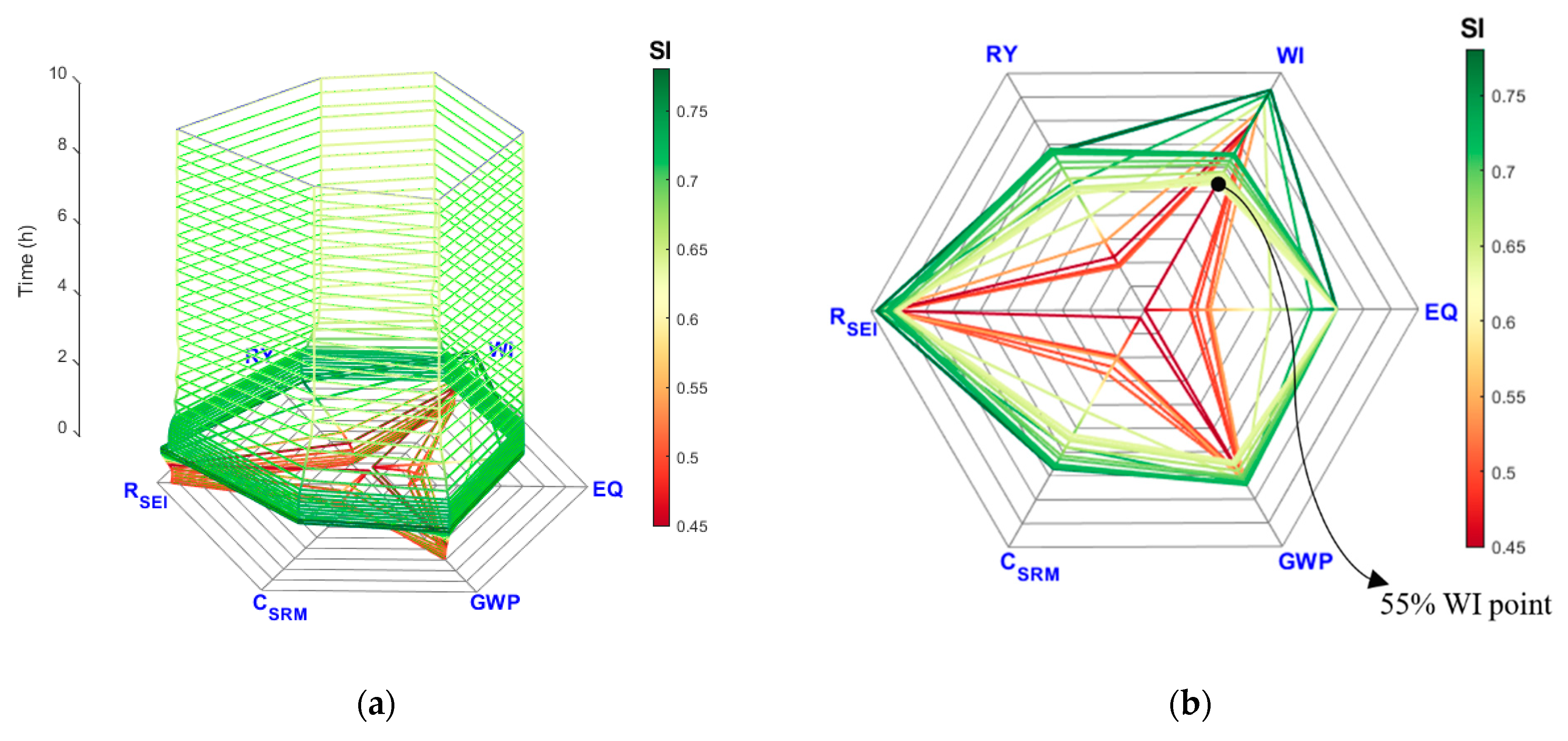
To further investigate the capability of the proposed sustainability-oriented process control framework, a more challenging case with D i n of 0.5 h−1, which represents a higher ethanol production rate with the same fermenter size is addressed in case 2. Operation with higher D i n can increase the fermenter productivity, which is an important performance indicator from the economic point of view. In this case, the setpoints, the manipulated variable boundaries, and the objective function of the controller are kept the same as in case 1. Figure 11 depicts the closed-loop simulation results for the output and input profiles. In this figure, it is shown that the implemented BIO-CS can also successfully eliminate the oscillations and drive this more challenging case to the desired setpoints. Note that the manipulated variables reach their upper boundaries in the first 2 h which cause higher water consumption and thus worsen the overall sustainability performance. Figure 12 shows the dynamic sustainability performance results for case 2 without the sustainability constraint. Compared to case 1, the overall sustainability performance of case 2 for the same obtained steady state is lower than that of case 1 due to the lower efficiency and more water usage for the high D i n operating condition. However, the dynamic sustainability performance shares similar characteristics with case 1 for the different zones: (1) 0–1 h with low sustainability performance; (2) 1–2.5 h for transient time before steady state; and (3) 2.5–10 h for steady state. From the control results with the sustainability constraint on WI in case 1, it is anticipated that the sustainability performance before steady state can be improved by adding a sustainability constraint on WI. Moreover, it is known from Figure 12 that the WI score for the obtained steady state is of 55.47%, and thus, a reasonable threshold of 55% is selected for the WI score constraint.
Figure 13 and Figure 14 show the input and output profiles for the closed-loop simulation as well as the dynamic sustainability performance, respectively, for the scenario with the WI constraint. It is shown in Figure 13 that the BIO-CS controller with the sustainability constraint can successfully drive the system to the setpoints within a more sustainable range while meeting the constraint (WI score > 55%). It is worth mentioning that the controller could not push the system to the setpoints if the WI score constraint was increased to 60%. This is because the controller fails to achieve the setpoints with such a harsh WI threshold (higher than the WI score of the obtained steady state). During transient time of 0–2.5 h, the process sustainability performance in terms of S I ¯ is 0.66, which increased by 16.86%, when compared to the unconstrained problem with S I ¯ of 0.56 during the same transience. Specifically, water consumption for the same time interval (0–2.5 h) dropped by 54.58%, from 0.0064 to 0.0029 m3/kg product (considering the water consumption in the fermentation reactor). To clearly show the comparison in terms of sustainability indicators for the two cases with/without the sustainability constraint, Figure 15 shows all the sustainability indicators at three representative time points: 0.36 h (the time of lowest WI score for the unconstrained scenario), 1 h (the time of highest WI score for the constrained scenario), and 10 h (the time that reached steady state). It is worth noting that, during transience, the sustainability indicators improve while the sustainability performance of the final steady states is exactly the same for these two scenarios, as shown in Figure 15. By comparing the input profiles in Figure 11 and Figure 13, it is found that the BIO-CS input profiles for the constrained problem have slightly higher oscillations, which might have been caused by the challenging sustainability constraint as the system is operating close to the boundary of the steady-state WI score.

6. Conclusions and Future Work

This work introduced and demonstrated the proposed novel sustainability-oriented control strategy to improve process sustainability during transient. Specifically, integrating process control with dynamic sustainability helps with the understanding of the dynamic characteristics of the system in terms of sustainability. Based on the analysis of the dynamic sustainability performance, regions with lower sustainability percentage can be detected and a reasonable constraint can be imposed on selected sustainability indicators so that the control actions can be optimized for improving the sustainability performance. Two case studies of a fermentation process with different dilution rates ( D i n ) were used to illustrate the application of the proposed dynamic sustainability performance visualization approach as well as the benefits of integrating a sustainability constraint into the BIO-CS control strategy. Such a framework successfully improved the sustainability performance of the two addressed cases by 9.65% and 16.86%, respectively, which corresponds to up to ~55% drop in water consumption during transience considering both cases. In the future, an online performance analysis system for locating the most important sustainability indicators can be developed to automatically provide the sustainability indicators for the process constraints. Also, the investigation of a dynamic operability method for guiding the constraint threshold selection would be important for improving the controller performance. In particular, such a method would provide an input–output dynamic mapping to systematically determine the achievability of the control objectives along with the indicator regions (defined by their upper and lower bounds) for different input values.

Author Contributions

This paper is a collaborative work among the authors. S.L. performed all simulations and wrote the manuscript. G.J.R.-M. helped with the analysis and supervision of the research work. F.V.L. helped with the paper writing and oversaw all technical aspects of the research work. All authors have read and agreed to the published version of the manuscript.

Funding

The authors gratefully acknowledge the financial support from U.S. EPA through award #DE-FE0012451.

Conflicts of Interest

The authors declare no conflict of interest.

Disclaimer

The views expressed in this contribution are those of the authors solely and do not necessarily reflect the views or policies of the U.S. EPA. Mention of trade names, products, or services does not convey and should not be interpreted as conveying, official U.S. EPA approval, endorsement, or recommendation.

Nomenclature

VariablesDefinition (Units)
A1/A2Exponential factors in Arrhenius equation
AMArea of membrane (m2)
ACConcentration analysis control
ATHeat transfer area (m2)
CiConcentration of component i (kg/m3)
Cp,rHeat capacity of the reactants (kJ/kg/K)
Cp,wHeat capacity of cooling water (kJ/kg/K)
CSRMSpecific raw material cost indicator
DinInlet fermentor dilution rate (h−1)
DjCooling water flow rate (h−1)
DoutOutlet fermentor dilution rate (h−1)
Dm,inInlet membrane dilution rate (h−1)
Dm,outOutlet membrane dilution rate (h−1)
Ea1/Ea2Activation energies (kJ/mol)
EQEnvironmental quotient indicator
f ( · ) Process model
GWPGlobal warming potential indicator
JControl objective
KSMonod constant (kg/m3)
KTHeat transfer coefficient (kJ/h/ m2/K)
k1Empirical constant (h−1)
k2Empirical constant (m3/kg · h)
k3Empirical constant (m6/kg2 · h)
msMaintenance factor based on substrate (kg/kg · h)
mpMaintenance factor based on product (kg/kg · h)
m ˙ p r o d u c t Production rate (kg/h)
MMixer
MWMolecular weight (g/mole)
α Membrane permeability (m/h)
PCorrection factor
p Parameters of the process model
P S Sustainability indicator percent score
P S m a x , i Maximum percent score for the specific indicator i
riProduction rate of component i (kg/m3)
RGas constant
RYReaction yield indicator
RSEISpecific energy intensity indicator
S I i Sustainability constraint i
S I ( t ) Dynamic sustainability index
S I ¯ Average sustainability index
S I t h Threshold value for sustainability index
TCTemperature control
TjTemperature of cooling water in the jacket (K)
Tw,inInlet temperature of cooling water (K)
TrTemperature of the reactor (K)
t 0 Initial time interval
t f Final time interval
u ( t ) Input variables
u ( τ ) The past input action for the controller
u ( t ) l b Lower boundary for input variables
u ( t ) u b upper boundary for input variables
VFFermentor volume (m3)
VMMembrane volume (m3)
VjCooling jacket volume (m3)
w i Weighting factors i
w 1 Penalty factor on the output variables for the controller
w 2 Penalty factor on the input variables for the controller
W I Water intensity indicator
WI u b Upper WI boundary (m3/kg)
WI l b Lower WI boundary (m3/kg)
x ( t ) State variables
x ˙ ( t ) Derivatives of state variable
x ( t ) l b Lower boundary for state variables
x ( t ) u b upper boundary for state variables
y ( t ) Output variables
y s p Setpoint for process controller
YsxYield factor based on substrate (kg/kg)
YpxYield factor based on product (kg/kg)
Greek Symbols
ρ r Reactants density (kg/m3)
ρ w Cooling water density (kg/m3)
μ Specific growth rate (h−1)
μ m a x Maximum specific growth rate (h−1)
Δ H Heat of fermentation reaction (kJ/kg)
Subscripts
eKey component inside the fermentor
e0Inlet key component to the fermentor
PProduct (ethanol) inside the fermentor
P0Inlet product to the fermentor
PMProduct (ethanol) inside the membrane
SSubstrate inside the fermentor
S0Inlet substrate to the fermentor
XBiomass inside the fermentor
X0Inlet biomass to the fermentor

Appendix A

Table A1. Parameter values for the fermentation process model
A 1 = 0.6225 K S = 0.5   kg / m 3
A 2 = 0.000646 K T = 360   kJ / ( m 2 · K · h )
A T = 0.06   m 2 m s = 2.16   kg / ( kg · h )
A M = 0.24   m 2 m P = 1.1   kg / ( kg · h )
C e , 0 = 0   kg / m 3 P = 4.54
C X , 0 = 0   kg / m 3 α = 0.1283   m / h
C S , 0 = 150.3   kg / m 3 V F = 0.003   m 3
C P , 0 = 0   kg / m 3 V M = 0.0003   m 3
C P M ,   0 = 0   kg / m 3 V j = 0.00006   m 3
C p , r = 4.18   kJ / ( kg · K ) Y s x = 0.0244498   kg / kg
C p , w = 4.18   kJ / ( kg · K ) Y P x = 0.0526315   kg / kg
E a 1 = 55   kJ / mol T i n = 30   ° C
E a 2 = 220   kJ / mol T w , i n = 25   ° C
k 1 = 16.0   h 1 Δ H = 220   kJ / mol
k 2 = 0.497   m 3 / ( kg · h ) ρ r = 1080   kg / m 3
k 3 = 0.00383   m 6 / ( k g 2 · h ) ρ w = 1000   kg / m 3
Table A2. Definitions and reference values for selected GREENSCOPE (Gauging Reaction Effectiveness for the ENvironmental Sustainability of Chemistries with a multi-Objective Process Evaluator) indicators.
CategoryIndicatorFormulaUnitSustainability Value
Best Case (100%)Worst Case (0%)
EfficiencyReaction Yield
(RY)
R Y = M a s s   o f   p r o d u c t T h e o r e t i c a l   m a s s   o f   p r o d u c t kg/kg1.00
Water Intensity
(WI)
W I = V o l u m e   o f   f r e s h   w a t e r   c o n s u m e d m a s s   o f   p r o d u c t m3/kg00.1
EnvironmentalEnvironmental Quotient
(EQ)
E Q = T o t a l   m a s s   o f   w a s t e M a s s   o f   p r o d u c t × U n f r i e n d l i n e s s   q u o t i e n t m3/kg02.5
Global Warming Potential (GWP) G W P = T o t a l   m a s s   o f   C O 2   e q u i v a l e n t s M a s s   o f   p r o d u c t kg/kg0Any waste released has a potency factor at least equal to 1
EconomicSpecific Raw Material Cost (CSRM) S R W C = R a w   m a t e r i a l   c o s t s M a s s   o f   p r o d u c t $/kg00.5
EnergySpecific Energy Intensity (RSEI) R S E I = N e t   e n e r g y   u s e d   a s   p r i m a r y   f u e l   e q u i v a l e n t M a s s   o f   p r o d u c t kJ/kg0100

References

  1. Martins, A.A.; Teresa, M.M.; Costa, C.A.V.; Sikdar, S.K. Framework for Sustainability Metrics. Ind. Eng. Chem. Res. 2006, 46, 2962–2973. [Google Scholar] [CrossRef]
  2. Sikdar, S.K. Sustainable Development and Sustainability Metrics. AIChE J. 2003, 49, 1928–1932. [Google Scholar] [CrossRef]
  3. Jacquemin, L.; Pontalier, P.-Y.; Sablayrolles, C. Life Cycle Assessment (LCA) Applied to The Process Industry: A Review. Int. J. Life Cycle Assess. 2012, 17, 1028–1041. [Google Scholar] [CrossRef] [Green Version]
  4. Cobb, C.; Schuster, D.; Beloff, B.; Tanzil, D. The AIChE Sustainability Index the Factors in Detail. Chem. Eng. Prog 2009, 111, 59–63. [Google Scholar]
  5. Chin, K.; Schuster, D.; Tanzil, D.; Beloff, B.; Cobb, C. Sustainability Trends in the Chemical Industry. Chem. Eng. Prog 2015, 111, 36–40. [Google Scholar]
  6. Institution of Chemical Engineers. The Sustainability Metrics: Sustainable Development Progress Metrics Recommended for Use in the Process Industries; IChemE: Warwickshire, UK, 2014. [Google Scholar]
  7. Ruiz-Mercado, G.J.; Gonzalez, M.A.; Smith, R.L. Sustainability Indicators for Chemical Processes: III. Biodiesel Case Study. Ind. Eng. Chem. Res. 2013, 52, 6747–6760. [Google Scholar] [CrossRef]
  8. Ruiz-Mercado, G.J.; Smith, R.L.; Gonzalez, M.A. Sustainability Indicators for Chemical Processes: I. Taxonomy. Ind. Eng. Chem. Res. 2012, 51, 2309–2328. [Google Scholar] [CrossRef]
  9. Ruiz-Mercado, G.J.; Smith, R.L.; Gonzalez, M.A. Sustainability Indicators for Chemical Processes: II. Data Needs. Ind. Eng. Chem. Res 2012, 51, 2329–2353. [Google Scholar] [CrossRef]
  10. Li, S.; Feliachi, Y.; Agbleze, S.; Ruiz-Mercado, G.J.; Smith, R.L.; Meyer, D.E.; Gonzalez, M.A.; Lima, F.V. A Process Systems Framework for Rapid Generation of Life Cycle Inventories for Pollution Control and Sustainability Evaluation. Clean Technol. Environ. Policy 2018, 20, 1543–1561. [Google Scholar] [CrossRef]
  11. Gao, J.; You, F. Endpoint-Oriented Life Cycle Optimization Models for Sustainable Design and Operations of Shale Gas Supply Chains with Modular Manufacturing. Comput. Aided Chem. Eng. 2018, 43, 591–596. [Google Scholar]
  12. Dubey, R.; Gunasekaran, A.; Papadopoulos, T.; Childe, S.J.; Shibin, K.T.; Wamba, S.F. Sustainable Supply Chain Management: Framework and Further Research Directions. J. Clean. Prod. 2017, 142, 1119–1130. [Google Scholar] [CrossRef] [Green Version]
  13. Lozano, F.J.; Lozano, R.; Freire, P.; Jiménez-Gonzalez, C.; Sakao, T.; Ortiz, M.G.; Trianni, A.; Carpenter, A.; Viveros, T. New Perspectives for Green and Sustainable Chemistry and Engineering: Approaches from Sustainable Resource and Energy Use, Management, and Transformation. J. Clean. Prod. 2018, 172, 227–232. [Google Scholar] [CrossRef]
  14. Ghosh, T.; Liu, X.; Bakshi, B.R. Including Ecosystem Services in Sustainable Process Design across Multiple Spatial Scales. Comput. Aided Chem. Eng. 2018, 44, 1837–1842. [Google Scholar]
  15. Bakshi, B.R. Toward Sustainable Chemical Engineering: The Role of Process Systems Engineering. Annu. Rev. Chem. Biomol. Eng. 2019, 10, 265–288. [Google Scholar] [CrossRef]
  16. Alanqar, A.; Ellis, M.; Christofides, P.D. Economic Model Predictive Control of Nonlinear Process Systems Using Empirical Models. AIChE J. 2015, 61, 816–830. [Google Scholar] [CrossRef] [Green Version]
  17. Mesbah, A. Stochastic Model Predictive Control: An Overview and Perspectives for Future Research. IEEE Control Syst. 2016, 36, 30–44. [Google Scholar]
  18. Zhang, Z.; Wu, Z.; Rincon, D.; Garcia, C.; Christofides, P.D. Operational Safety of Chemical Processes via Safeness-Index Based MPC: Two Large-Scale Case Studies. Comput. Chem. Eng. 2019, 204–215. [Google Scholar] [CrossRef]
  19. Daoutidis, P.; Zachar, M.; Jogwar, S.S. Sustainability and Process Control: A Survey and Perspective. J. Process Control 2016, 44, 184–206. [Google Scholar] [CrossRef]
  20. Rossi, F.; Manenti, F.; Pirola, C.; Mujtaba, I. A Robust Sustainable Optimization & Control Strategy (RSOCS) for (fed-)Batch Processes towards the Low-cost Reduction of Utilities Consumption. J. Clean. Prod. 2016, 111, 181–192. [Google Scholar]
  21. Zhu, Q.; Lujia, F.; Mayyas, A.; Omar, M.A.; Al-Hammadi, Y.; Al Saleh, S. Production Energy Optimization Using Low Dynamic Programming: A Decision Support Tool for Sustainable Manufacturing. J. Clean. Prod. 2015, 105, 178–183. [Google Scholar] [CrossRef]
  22. Li, S.; Mirlekar, G.; Ruiz-Mercado, G.J.; Lima, F.V. Development of Chemical Process Design and Control for Sustainability. Processes 2016, 4, 23. [Google Scholar] [CrossRef] [Green Version]
  23. Ruiz-Mercado, G.J.; Smith, R.L.; Gonzalez, M.A. GREENSCOPE.xlsm Tool; US Environmental Protection Agency: Cincinnati, OH, USA, 2013.
  24. Mirlekar, G.; Li, S.; Lima, F.V. Design and Implementation of a Biologically Inspired Optimal Control Strategy for Chemical Process Control. Ind. Eng. Chem. Res. 2017, 56, 6468–6479. [Google Scholar] [CrossRef]
  25. Miroslav Fikar Dynopt Solver. Available online: https://www.uiam.sk/~fikar/research/dynopt/dynopt.htm (accessed on 10 September 2019).
  26. Mirlekar, G.; Gebreslassie, B.H.; Li, S.; Diwekar, U.M.; Lima, F.V. An Integrated Biomimetic Control Strategy with Multi-agent Optimization for Nonlinear Chemical Processes. In Proceedings of the 2018 IFAC ADCHEM Symposium, Shenyang, China, 25–27 July 2018; Volume 51, pp. 55–60. [Google Scholar]
  27. Mirlekar, G.; Pezzini, P.; Bryden, M.; Tucker, D.; Lima, F.V. A Biologically-Inspired Optimal Control Strategy (BIO-CS) for Hybrid Energy Systems. In Proceedings of the 2017 American Control Conference (ACC), Seattle, WA, USA, 24–26 May 2017; pp. 4821–4826. [Google Scholar]
  28. Mirlekar, G.; Al-Sinbol, G.; Perhinschi, M.; Lima, F.V. A Biologically-Inspired Approach for Adaptive Control of Advanced Energy Systems. Comput. Chem. Eng. 2018, 117, 378–390. [Google Scholar] [CrossRef]
  29. Lima, F.V.; Georgakis, C. Dynamic Operability for the Calculation of Transient Output Constraints for Non-Square Linear Model Predictive Controllers. In Proceedings of the 2009 IFAC ADCHEM Symposium, Istanbul, Turkey, 12–15 July 2009. [Google Scholar]
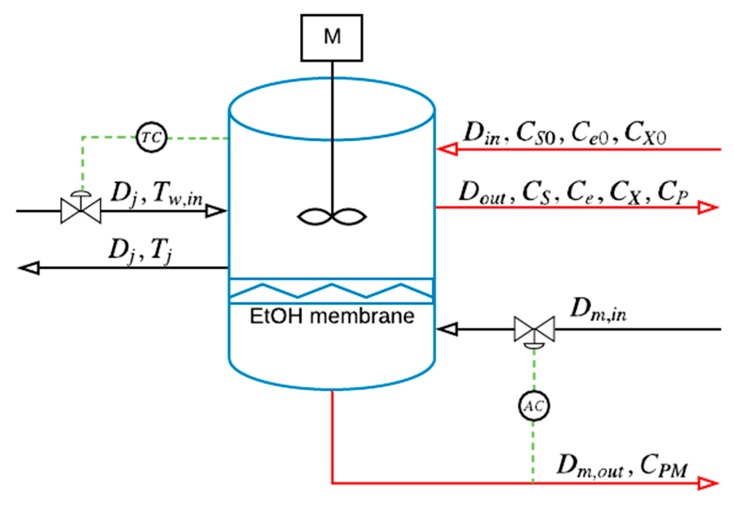
Figure 1. Schematic diagram of the fermentation reactor.
Processes 08 00310 g001
Figure 2. Proposed framework for novel sustainable process control.
Processes 08 00310 g002
Figure 3. Visualization method for monitoring high-dimensional sustainability performance: (a) 2D radar plot; (b) 3D radar plot.
Processes 08 00310 g003
Figure 4. Process open-loop simulation dynamics: (a) concentration profiles of different components and (b) reactor temperature profile.
Processes 08 00310 g004
Figure 5. Dynamic sustainability performance of open-loop simulation (red represents less sustainable, while green more sustainable according to calculated SI values): (a) 3D sustainability indicator dynamic radar plot; (b) 2D projection of sustainability indicator radar plot.
Processes 08 00310 g005
Figure 6. Case 1—closed-loop simulation without sustainability constraint: output (y1 and y2) and input (u1 and u2) profiles.
Processes 08 00310 g006
Figure 7. Case 1—dynamic sustainability performance without sustainability constraint: (a) 3D sustainability indicator dynamic radar plot; (b) 2D projection of sustainability indicator radar plot.
Processes 08 00310 g007
Figure 8. Case 1—closed-loop simulation with sustainability constraint: output (y1 and y2) and input (u1 and u2) profiles.
Processes 08 00310 g008
Figure 9. Case 1—dynamic sustainability performance with sustainability constraint: (a) 3D sustainability indicator dynamic radar plot; (b) 2D projection of sustainability indicator radar plot.
Processes 08 00310 g009
Figure 10. Case 1—comparison between control without Water Intensity (WI) constraint (red line) and control with WI constraint (blue line) at three representative sample points.
Processes 08 00310 g010
Figure 11. Case 2—closed-loop simulation without sustainability constraint: output (y1 and y2) and input (u1 and u2) profiles.
Processes 08 00310 g011
Figure 12. Case 2—dynamic sustainability performance without sustainability constraint: (a) 3D sustainability indicator dynamic radar plot; (b) 2D projection of sustainability indicator radar plot.
Processes 08 00310 g012
Figure 13. Case 2—closed-loop simulation with sustainability constraint: output (y1 and y2) and input (u1 and u2) profiles.
Processes 08 00310 g013
Figure 14. Case 2—dynamic sustainability performance with sustainability constraint: (a) 3D sustainability indicator dynamic radar plot; (b) 2D projection of sustainability indicator radar plot.
Processes 08 00310 g014
Figure 15. Case 2—comparison between control without WI constraint (red line) and control with WI constraint (blue line) at three representative sample points.
Processes 08 00310 g015