Article

Experimental Study and Application of Rheological Properties of Coal Gangue-Fly Ash Backfill Slurry

1
School of Energy and Mining Engineering, China University of Mining & Technology, D11 Xueyuan Road, Haidian District, Beijing 100083, China
2
State Key Laboratory of Coal Resources and Safe Mining, China University of Mining and Technology, Beijing, D11 Xueyuan Road, Haidian District, Beijing 100083, China
*
Author to whom correspondence should be addressed.
Processes 2020, 8(3), 284; https://doi.org/10.3390/pr8030284
Submission received: 19 January 2020 / Revised: 24 February 2020 / Accepted: 26 February 2020 / Published: 3 March 2020
(This article belongs to the Section Materials Processes)

Abstract

:
From the perspective of resource recovery and environmental protection, coal gangue-fly ash cemented backfill coal mining has become an important direction for the green development of coal mines in recent years. Analysis of the rheological parameters of backfill slurry is the basic principle to design a backfill pipeline system. Coal gangue-fly ash backfill slurry has a mass concentration of 76% to 79% and a maximum particle size 20 mm. Therefore, it is difficult to use conventional rheometers for experimental analyses of the rheological parameters of such fluids. We developed a rheometer for high-concentration coal gangue backfill slurry (HCGS rheometer) based on the coal gangue-fly ash backfill practice of Gonggeying Mine, and analyzed the rheological properties of the backfill slurry. The experimental results showed that the Reynolds number of the coal gangue-fly ash backfill slurry was much smaller than the critical Reynolds number, indicating the flow state in the pipeline was laminar. Based on these results, it may be more appropriate to control the mass concentration to 77% to 78%, and the suggested fly ash content is 25%. This work provides a scientific basis to optimize the backfill parameters and pipeline system in coal mines.

1. Introduction

China’s “three unders” (i.e., under buildings, water bodies, and roads) are estimated to host approximately 14 billion tons of coal. With the rapid development of China’s coal industry, the “three unders’” coal pressure has been steadily rising. Therefore, to safely and efficiently mine “three under” coal while preserving the environment has become a major issue that needs to be solved [1,2,3]. The backfill mining method is an effective approach to control mining subsidence and improve the resource recovery rate while extracting coal from the “three unders.” This approach has become an important direction to support green coal mining in recent years [4,5,6,7,8].
The Laoha River crosses Gonggeying mine field to the east. The topsoil layer is 4–6 m thick; the lower layer is the alluvial sand layer, which is a strong aquifer with a thickness of 20–23 m. The mine primarily extracts No. 6 coal, with an inclination of 5–14°, an average thickness of 15 m, and a buried depth of 120–150 m. To avoid flooding accidents, the original design is the conventional roof fall management method that leaves approximately 12 million tons of waterproof coal pillars; this is extremely detrimental to the utilization of resources and service life of the mine [9,10]. To extract coal found under water, the Gonggeying Coal Mine used coal gangue-fly ash cemented backfill for the pillars.
The coal gangue-fly ash cemented backfill mining method uses cement, coal gangue, and fly ash to prepare a high-concentration backfill slurry that is transported underground through pipelines. This approach can effectively control mining subsidence and improve the resource recovery rate while more fully utilizing the coal gangue and fly ash resources [11,12,13]. In practice, the mass concentration of the backfill slurry reaches 76% to 79%, of which the proportion of coal gangue in the solid material is 60% to 80% and the maximum particle size approaches 20 mm. As a result, the pipelines are prone to blockage [14,15,16]. Therefore, the backfill parameters and the optimization of the pipeline system require improvements to the fluidity of the coal gangue-fly ash backfill slurry to increase the stability of pipeline transportation. To date, several types of viscometers, such as parallel plate, coaxial cylinder, and capillary, are only suitable to measure the rheological parameters of suspensions or fine-grained slurries. There is no special testing instrumentation for coarse aggregate slurry, and the pipeline experimental test method has a large workload at high costs, which is inconvenient for the rheological parameter tests with high-concentration coal gangue backfill slurry [17,18,19]. Therefore, this paper explores and develops a high-concentration coal gangue backfill slurry rheometer (HCGS rheometer) and the corresponding rheological parameter testing methods.

2. Structural Composition and Testing Principle of the HCGS Rheometer

2.1. Structural Composition of the HCGS Rheometer

Traditional rotary viscometers have weak stirring and a relatively small capacity. For example, the NXS-11A rotary viscometer has a maximum stirring power of 20 W and a slurry volume of 60 mL. Thus, these sensors are only suitable for testing the viscosity parameters of fine particle slurries, such as cement and fine tail slurries [19,20]. This study used the theory of slurry rheology to develop an HCGS rheometer that could measure the characteristics of coarse aggregates and the viscosity of the slurry [21,22,23,24]. Thus, the rheological parameters of high-concentration filler-infused slurries with a maximum solid particle size of 20 mm could be tested. The coarse aggregate slurry was well-stirred and rotated during the test and the inner diameter of the stirring cylinder could not be fewer than four times the maximum particle size [21,25]. The maximum particle diameter of the coal gangue was 20 mm, and the inner diameter of the HCGS rheometer stirring cylinder was five times the maximum particle diameter, i.e., 100 mm.
The developed HCGS rheometer used a high-power system and a large-capacity stirring system. The structure is shown in Figure 1. It mainly included the following six subsystems:
(1) Power system: DC velocity-regulating motor, rated power 185 W, maximum velocity 1000 r/min.
(2) Sensing system: Torque sensor that simultaneously measured the torque and rotating velocity of the stirring shaft; torque range was 0–0.2 N∙m and the velocity range was 0–2000 r/min.
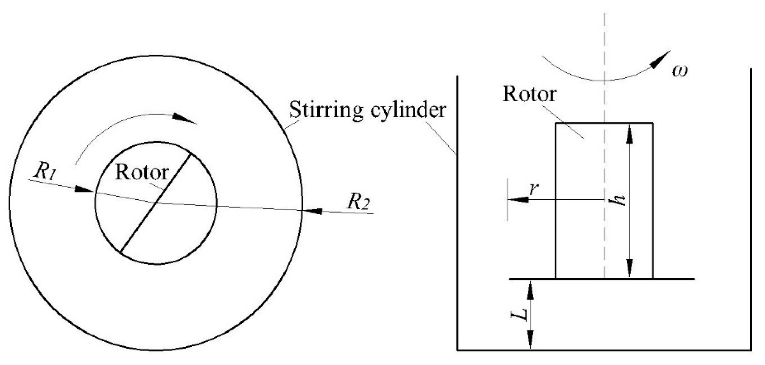
(3) Stirring system: Paddle-type stirring rotor with radius R 1 = 2 cm and height h = 3 cm; stirring cylinder with radius R 2 = 5 cm, height H = 12 cm, and testing volume V = 650 mL.
(4) Control system: Stepless velocity governor.
(5) Digital display unit: Digital display for real-time torque and velocity. When necessary, the digital display instrument can be connected to the computer for automatic collection and analysis of testing data.
(6) Auxiliary unit: Elastic coupling, base, bracket, and photoelectric signal isolator.

2.2. Test Principle of the HCGS Rheometer

The basic principle of the HCGS rheometer to determine the rheological parameters was that the paddle-type stirring rotor drove the slurry in the stirring cylinder to create circular motion under the drive of a motor. The measured fluid between the stirring rotor and the stirring cylinder was subjected to shear. When the rotor rotated at a certain angular velocity, the torque and rotor velocity on the shaft could be measured using the torque sensor and converted into a number for display. Therefore, the corresponding relationship between the torque and rotating velocity in the slurry experiment could be obtained through testing, and the rheological parameters of the slurry could be calculated from the associated relationship.
A schematic diagram of the rotor rotation is shown in Figure 2 where R 1 is the radius of the rotor, m; R 2 is the radius of the stirring cylinder, m; h is the height of the stirring rotor, m; r is the distance from any point on the inner space of the stirring cylinder to the central axis of the rotor, m; and ω is the rotational angular velocity of the slurry at r , rad/s.
While stirring the slurry, for any point in the annular space between the stirring rotor and the wall of the stirring cylinder, we have
M = 2 π r 2 · h τ
where M is the stirring torque, N·m and τ is slurry shear stress, Pa. Several studies and practices have shown that the rheological properties of a highly concentrated filler slurry can be expressed using a Bingham model. The associated rheological equation can be expressed as [26,27]
τ = τ 0 + η γ ˙ = τ 0 + η d u d r
where τ is the shear stress, Pa; τ 0 is the slurry yield stress, Pa; η is the plastic viscosity of the slurry, Pa·s; γ ˙ is the shear rate, s−1; and u is the rotational linear velocity of the slurry, m/s.
Due to the velocity of u = r ω at any point, Equation (2) can be changed to:
τ = τ 0 + η r d ω d r
Equation (3) is substituted into Equation (1) to obtain:
M = 2 π h r 2 ( τ 0 + η r d ω d r )
The above formula can be transformed into:
d ω = ( M / ( 2 π h r 3 ) τ 0 / ( η r ) ) d r
Definite integration is performed on the above formula to arrive at:
0 Ω d ω = R 1 R 2 ( M / ( 2 π h η r 3 ) τ 0 / ( η r ) ) d r
where Ω is the angular velocity of the rotor, rad/s.
After integration, the following relationship exists between the stirring torque M , the rotor angular velocity Ω , and the rheological parameter τ 0 , η :
Ω = ( M / 4 π h η ) ( 1 / R 1 2 1 / R 2 2 ) ( τ 0 / η ) ln ( R 2 / R 1 )
In Equation (7), the radius R 1 of the stirring rotor, the radius R 2 of the stirring drum, and the height h of the rotor are known constant values, which give
k 1 = ( 1 / 4 π h ) ( 1 / R 1 2 1 / R 2 2 ) ,   k 2 = ln ( R 2 / R 1 )
It is seen from Equation (8) that k 1 and k 2 are constant parameters related to the rheometer testing system. Therefore, Equation (7) can be simplified to:
M = ( η Ω + k 2 τ 0 ) / k 1
For a slurry to be measured, its rheological parameters η and τ 0 should be set to specific values, so the relationship between the torque and rotor angular velocity can be expressed as:
M = a Ω + b
From Equations (9) and (10), we have:
η = k 1 a ,   τ 0 = ( k 1 / k 2 ) b
Based on the above analysis, the rheological parameters of the coal gangue-fly ash backfill slurry could be obtained through the following test analysis process. First, the stirring torque M was measured at different stirring velocities Ω with the HCGS rheometer used to obtain the slurry stirring curve M Ω . Second, the a and b values were obtained from the M Ω relational formula. Third, the η and τ 0 values of the slurry were calculated from Equation (11). This process is shown in Figure 3.

3. Experimental Analysis of Rheological Properties for Backfill Slurry

3.1. Experimental Scheme

The primary influencing factors to the rheological parameters for the coal gangue-fly ash backfill slurry are as follows:
(1) Slurry concentration. If the slurry concentration is too low, the amount of dewatering underground will be high and its strength will be low. If the slurry concentration is too high, its transportation will be difficult.
(2) Particle size of solid material, which is primarily fly ash and coal gangue. If the proportion of fly ash is low, the content of fine particles will be small, the slurry homogeneity will be poor, the particles will settle significantly, and the fluidity will be poor. If the proportion of fly ash is too high, the content of fine particles will be large, the slurry will be thick, and the pipe transportation resistance will be large.
Therefore, this paper considers the rheological parameters of the slurry under different slurry concentrations and fly ash contents.
The coal gangue used in the experiment was taken from the gangue crushing workshop of Gonggeying Mine, and the particle size was ≤20 mm. The test grain composition after testing is shown in Table 1. Fly ash was taken from a coal-fired power plant near the mine, and the particle size distribution test was performed on the fly ash using a laser particle size analyzer. The test results are shown in Figure 4.
The experiments were divided into the following two groups:
(A) The mass ratio of each raw material in the backfill solid remained unchanged at a cement:fly ash:coal gangue ratio of 5:25:70. The slurry mass concentration varied from 76% to 79% in integer values.
(B) The mass concentration of the slurry remained unchanged at 78%. The amount of cement in the backfill solids was 5%, and the mass ratio of fly ash and coal gangue was varied. The proportions of fly ash and coal gangue in the solid were 15:80, 20:75, 25:70, and 30:65.

3.2. Test Analysis

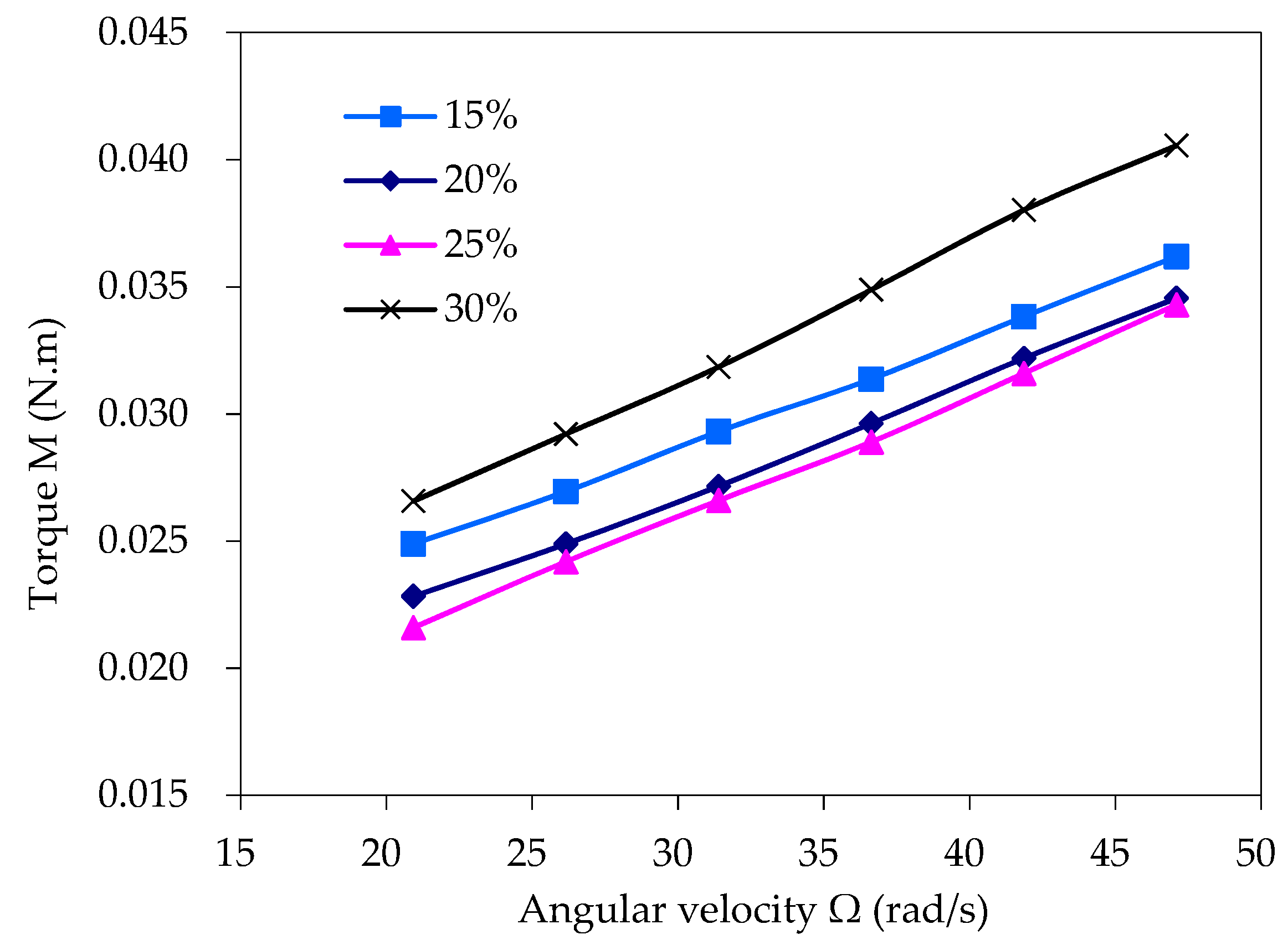
The rheometer was used to test the two slurry groups (both A and B) using the experimental scheme. The experiments showed that the test process was unstable when the angular velocity of the stirring rotor was lower than 20 rad/s. Therefore, the relationship between the torque and velocity obtained when the angular velocity of the stirring rotor was higher than 20 rad/s are shown in Figure 5 and Figure 6. The curves for the relationship between the torque and angular velocity are linearly fit, as shown in Figure 5 and Figure 6, and the obtained relational formulas for M Ω are shown in Table 2. The rotor radius of the HCGS rheometer was R 1 = 2 cm, the radius of the stirring cylinder was R 2 = 5 cm, and the rotor height was h = 3 cm. From the values of a and b in Table 2, the rheological parameters of each sample slurry could be calculated using Equations (8)–(11), as shown in Table 3.
The rheological parameters of the slurry in Table 3 indicate the following:
(1) Under a certain cement to coal gangue to fly ash ratio, larger slurry mass concentrations caused the slurry viscosity, the yield stress τ 0 , and the plastic viscosity η to tend to increase overall. When the concentration increased from 78% to 79%, the rheological parameters were significantly increased; therefore, it is appropriate to control the mass concentration to 77% to 78%.
Some scholars have studied the flow characteristics of high-concentration backfill slurry containing coarse aggregate under different concentrations by using pipeline experimental test methods [17]. The results show that the yield stress τ 0 and plastic viscosity η increase with the increase of slurry concentration, and the higher the slurry concentration, the greater the rate of increase. When a certain critical concentration is reached, τ 0 and η increase sharply with increasing concentration. Backfill slurry with different materials has different critical concentrations. In this paper, the viscosity characteristics of coal gangue-fly ash backfill slurry tested by the HCGS rheometer also followed the similar law, and the corresponding critical concentration was 78%.
(2) When the mass concentration of the slurry was unchanged at 78%, the plastic viscosity η increased with the fly ash content. The yield stress τ 0 decreased first and then increased, and was the lowest when fly ash content was 25%.
High-concentration backfill slurry with suitable content of fine particles has good stability and fluidity [22,28,29]. The addition of fine particles increases the viscosity of the slurry, slows down the sedimentation of coarse particles in the slurry, and makes the vertical distribution of the slurry concentration more even, which is beneficial to reducing the flow resistance. In addition, the fine particles are filled between the coarse particles and act as a lubricant, which can reduce the frictional resistance of the movement. When the content of fine particles in the slurry reaches a certain amount, the gaps between coarse particles are filled with fine particles and the coarser particles are in a suspended motion state. However, if more fine particles are added, the viscosity and flow resistance of the slurry will increase sharply. Therefore, the suitable content of fine particles is conducive to the flow of the slurry. In the coal gangue-fly ash backfill slurry studied in this paper, coal gangue in the aggregate was a coarse particle and fly ash was a fine particle. The suitable content of fly ash was 25%, which gave the coal gangue-fly ash backfill slurry good fluidity.

4. Discrimination of Flow State in a Backfill Slurry Conveying Pipeline

The Reynolds number Re of the slurry and the critical Reynolds number Re c are compared to determine whether the slurry flow in the pipeline is laminar or turbulent. When Re Re c , the flow of slurry in the pipeline is laminar, and when Re > Re c , the flow of slurry in the pipeline is turbulent. The viscosity in the expression for the Reynolds number varies with the concentration, while the viscosity is related to the flow state [17,30].
For Bingham plastics, the Reynolds number is calculated based on plastic viscosity η as [21]:
Re = U D ρ / η
where ρ is the density of the slurry, kg/m3; D is the inner diameter of the pipeline, m; and U is the flow velocity of the slurry, m/s.
The inner diameter of the coal gangue-fly ash backfill slurry conveying pipeline was D = 0.1–0.2 m, the normal flow rate was U = ≤2 m/s, and the slurry density was ρ = 1900 kg/m3. Therefore, based on the values of η from Table 3, the flow Reynolds number for the slurry with mass concentrations from 76% to 79% could be calculated from Equation (12), as shown in Table 4.
The calculation for the critical Reynolds number based on the plastic viscosity η is
Re c = 2100 / [ 1 ( 4 / 3 ) a c + ( 1 / 3 ) a c 4 ]
where a c is the ratio of yield stress to shear stress at the pipe wall, which is
a c = τ 0 / τ w
where τ w is the shear stress at the pipe wall, which can be calculated as
τ w = η ( 8 U / D ) + ( 4 / 3 ) τ 0
Combined with the η and τ 0 values from Table 3, when D = 0.1 m and D = 0.2 m, the critical Reynolds number of the slurry flow with mass concentrations from 76% to 79% could be calculated from Equations (13) to (15), as seen in Table 4.
Table 4 shows that the Reynolds numbers of the coal gangue-fly ash backfill slurry with mass concentrations from 76% to 79% were far less than the critical Reynolds numbers. Therefore, the flow state was considered to be laminar.

5. Engineering Applications

The design backfill capacity of Gonggeying Coal Mine is Q = 90 m3/h. The total length from the backfill pipeline inlet to the underground backfill pipeline outlet is 1069 m with a vertical height of 118 m. The mass concentration of the backfill slurry is 77% to 78%, and the mass ratio of solids for cement:fly ash:coal gangue is 5:25:70.

5.1. Determination of Friction Resistance Coefficient and Inner Diameter of the Backfill Pipeline

The flow state for high-concentration coal gangue-fly ash backfill slurry was close to a Bingham plastic. In pipeline transportation, the pipeline friction resistance coefficient can be calculated using Equation (16) [15,31]:
f = ( 16 / 3 D ) τ 0 + η ( 32 U / D 2 )
where f is the friction resistance coefficient, Pa/m; D is the inner diameter of the pipeline, m; and U is the average flow velocity of the slurry in the pipeline, m/s.
The diameter of the backfill pipeline not only affects the backfill capacity, but also the stability and safety of the backfill system [32,33]. If the pipe diameter is too small, the pipeline resistance is large enough that it will be severely worn. This limits the backfill capacity so that the actual requirements of the mine production will not be met. If the pipe diameter is too large, pipeline resources will be wasted, and the small slurry flow rate will cause solids to settle and block the pipe or cause slurry to not fill the pipes. This can cause damaging effects such as jet impacts and cavitation in the pipeline, which reduces its service lifetime [34,35]. Based on the above factors, for high-concentration coal gangue-fly ash backfill slurry, the appropriate pipe diameter should be able to maintain a slurry flow rate in the pipe between 1.2 to 1.8 m/s.
Based on the design backfill ability and the rheological parameters τ 0 and η of the backfill slurry as obtained from the testing and analysis results given in Table 3, the frictional resistance coefficients under different pipe diameters were calculated from Equation (16), as shown in Table 5. The table shows that the inner diameter of the pipeline D was 0.15 m, so a slurry flow velocity U of 1.42 m/s was appropriate. When the mass concentration of the slurry was 77% to 78%, the corresponding frictional resistance coefficient f was 7.10–7.84 kPa/m.

5.2. Backfill Pump Working Pressure

Based on the dimensions of Gonggeying Coal Mine, when the slurry flow Q was 90 m3/h and its mass concentration was 78%, the working pressure of the backfill pump was
P = ( 1 + k ) L f Δ H ρ g = 1.1 × 1069 × 7.84 × 10 3 118 × 1900 × 9.8 = 7.02 × 10 6   Pa = 7.02   ( MPa )
where L is the total length of the pipeline at 1069 m; f is the friction coefficient of the pipeline at 7.84 kPa/m; k is the local resistance coefficient taken as 10%; Δ H is the vertical height of the pipeline at 118 m; and ρ is the slurry density at 1900 kg/m3.
Therefore, under the conditions of backfill flow Q at 90 m3/h, the working pressure of the backfill pump was 7.02 MPa. Based on the above analysis and combined with the standard configuration of the backfill pump, a backfill pump with a flow rate Q of 90 m3/h and a rated pump pressure P of 10 MPa was selected.

6. Conclusions

(1) Based on the characteristics of the coarse aggregate, the high viscosity from the coal gangue backfill slurry, and the principle of rheological parameter testing, a rheometer for high-concentration coal gangue backfill slurries was developed.
(2) The developed HCGS rheometer was based on the theory of slurry rheology and could test the relationship between the stirring torque and the rotor velocity in the slurry experiment to obtain the rheological parameters of yield stress τ 0 and plastic viscosity η .
(3) The experimental results for the rheological properties of the coal gangue-fly ash backfill slurry showed the following: (i) As the slurry concentration increased, the yield stress τ 0 and plastic viscosity η tended to increase. When the concentration increased from 78% to 79%, the rheological parameters increased significantly; therefore, it was more appropriate to control the backfill slurry concentration to between 77% and 78%. (ii) As the fly ash content increased, the plastic viscosity η increased, while the yield stress τ 0 initially decreased before increasing. The lowest yield stress was at a fly ash content of 25%, which was considered to be the appropriate value.
(4) The Reynolds number Re of the coal gangue-fly ash backfill slurry was much smaller than the critical Reynolds number Re c . Therefore, the flow state of the slurry in the pipeline was laminar.
(5) Based on the actual working conditions, the resistance coefficient of the backfill pipeline was calculated, and the reasonable pipe diameter was analyzed to provide a scientific basis for the selection of the backfill pump.

Author Contributions

Y.W. conceived and performed the experiments, and wrote the paper; Y.H. (Yucheng Huang) reviewed the paper; Y.H. (Yuxin Hao) analyzed the data. All authors have read and agreed to the published version of the manuscript.

Funding

This study was supported by the National Key Research and Development Program of China (grant number No.2018YFC0808403).

Conflicts of Interest

The authors declare no conflict of interest.

References

  1. Hu, B.N. Backfill Mining Technology and Development Tendency in China Coal Mine. Coal Sci. Tech. 2012, 40, 1–5. [Google Scholar] [CrossRef]
  2. Sun, X.K.; Zhao, Q.M.; Shi, X.Y. Research and application on the technology of paste backfilling fully mechanized in residual strip pillar. J. Min. Safety Eng. 2017, 34, 650–654. [Google Scholar] [CrossRef]
  3. Zhang, H.X. Thinking on the Technology of Coal Mining under Buildings, Railways and Water-body in Future. Coal Min. Tech. 2011, 16, 1–3. [Google Scholar] [CrossRef]
  4. Guo, W.J.; Zhang, X.G.; Shi, J.W.; Li, Y.Y. Present Situation of Research on Backfilling Mining Technology in Mines and Its Application Prospect. J. Shandong Univ. Sci. Tech. (Nat. Sci.) 2010, 29, 24–29. [Google Scholar] [CrossRef]
  5. Huang, Y.C.; Feng, R.M.; Wang, H.P.; Zhao, W.P.; Liu, Y.F. The Coal Mining Mode of Paste-like Fill and Its Application Prospects. In Proceedings of the Advances in Civil Engineering, Pts 1–6, Kunming, China, 29–31 July 2011; pp. 3744–3748. [Google Scholar]
  6. Hui, G.L. Present Situation and Development of Filling Mining Technology in Coal Mines in China. Coal Eng. 2010, 2, 21–23. [Google Scholar]
  7. He, L. Application and Analysis of Filling Mining Methods of Coal Mines. Energy. Energy Conserv. 2016, 9, 183–184. [Google Scholar] [CrossRef]
  8. Li, Z.B. Present Situation and Development Trend of Filling Mining Technology in Coal Mines in China. Sci. Tech. Innov. Appl. 2014, 23, 105. [Google Scholar]
  9. Liu, Z.G.; Hu, J.Y.; Yao, L.Z. Ways and methods to extend the service life of mines. Zhongzhou Coal. 2006, 1, 21–74. [Google Scholar]
  10. Zhang, H.X.; Guo, W.J. New Technology of Coal Mining under Buildings, Railways and Water-Body; China University of Mining and Technology Press: Beijing, China, 2008; pp. 81–89. [Google Scholar]
  11. Lu, Y.Z. Research on the Movement Law of Overburden Rock under the Control of Coal Gangue Paste-Like Cementing. Master’s Thesis, Central South University, Changsha, China, 30 June 2006. [Google Scholar]
  12. Liu, J.G.; Zhao, Q.B. Comprehensive mechanized filling coal mining. J. China Coal Soc. 2010, 35, 1413–1418. [Google Scholar] [CrossRef]
  13. Qiu, M.; Shi, L.Q.; Yu, X.G.; Gao, W.F.; Shi, Y.K. On preventing the high pressure water-inrush from floor with paste-like backfill mining. J. Min. Safety Eng. 2016, 33, 409–414. [Google Scholar] [CrossRef]
  14. Huang, Y.C. Mine Filling Theory and Technology; Metallurgical Industry Press: Beijing, China, 2014; pp. 199–203. [Google Scholar]
  15. Chen, Y.J.; Zhao, B.W. Comprehensive Mechanized Paste Filling Coal Mining Technology; China Coal Industry Press: Beijing, China, 2012; pp. 17–18. [Google Scholar]
  16. Yang, Z.Q.; Yao, W.X.; Gao, Q.; Gui, H.G. Filling process and key technology of Pipeline Gravity Transport for Rod Mill Sand Filling Slury. J. Xinjiang Univ. (Nat. Sci. Edit.) 2016, 33, 221–228. [Google Scholar] [CrossRef]
  17. Liu, T.Y. Filling Mining Technology and Application; Metallurgical Industry Press: Beijing, China, 2001; pp. 58–64. [Google Scholar]
  18. Wang, S.Y.; Wu, A.X.; Ruan, Z.E.; Chen, S.M. Rheological properties of paste slurry and influence factors based on pipe loop test. J. Central South Univ. (Sci. Tech.) 2018, 49, 2519–2525. [Google Scholar]
  19. Zou, Z.Q.; Gao, Q.; Nan, S.Q. Research on the Rheological Properties of Cementing Material with Full Tailings based on Fill Stoping. Met. Mine. 2012, 12, 132–135. [Google Scholar]
  20. Wang, G.J.; Chen, G.R. Coaxial cylinder viscometer and its application in architectural coatings industry. Chem. Build. Mater. 1987, 3, 9–11. [Google Scholar]
  21. Fei, X.J. Hydraulics for Slurry and Granular Material Transport; Tsinghua University Press: Beijing, China, 1994; pp. 52–56. [Google Scholar]
  22. Liu, K.R. Theoretical Foundation of Filling; Metallurgical Industry Press: Beijing, China, 2012; pp. 54–56. [Google Scholar]
  23. Senapati, P.K.; Mishra, B.K.; Parida, A. Analysis of friction mechanism and homogeneity of suspended load for high concentration fly ash & bottom ash mixture slurry using rheological and pipeline experimental data. Powder Technol. 2013, 250, 154–163. [Google Scholar] [CrossRef]
  24. Qiu, Z.F.; Cao, T.; Li, Y.S.; Wang, J.J.; Chen, Y.L. Rheological Behavior and Modeling of a Crushed Sandstone-Mudstone Particle Mixture. Processes 2018, 6, 192. [Google Scholar] [CrossRef] [Green Version]
  25. Ma, B.G. New Pumped Concrete Technology and Construction; Chemical Industry Press: Beijing, China, 2006; pp. 247–250. [Google Scholar]
  26. Deng, D.Q.; Gao, Y.T.; Yang, Y.L.; Wu, S.C. Rheological properties of full tailings slurry in pipeline transportation based on the hydromechanics. Chin. J. Eng. 2009, 31, 1380–1384. [Google Scholar] [CrossRef]
  27. Peng, X.C. Filling Theory and Application; Central South University of Technology Press: Changsha, China, 1998; pp. 94–96. [Google Scholar]
  28. Wang, X.M.; Xiao, W.G.; Zhang, Q.L. Deep Well Mine Filling Theory and Technology; Central South University Press: Beijing, China, 2005; pp. 101–104. [Google Scholar]
  29. Zhang, Q.L.; Xie, S.Q.; Zheng, J.J.; Wang, X.M. Sedimentation law research and transportation feasibility study of backfilling slurry. J. Chongqing Univ. 2011, 34, 105–109. [Google Scholar]
  30. Huang, W.X. Engineering Fluid Mechanics; Chemical Industry Press: Beijing, China, 2001; pp. 144–145. [Google Scholar]
  31. Wu, A.X.; Ai, C.M.; Wang, Y.M.; Yang, X.X.; Zhou, F.L. Test and mechanism analysis on improving rheological property of paste with pumping agent. J. Central South Univ. (Sci. Tech.) 2016, 47, 2752–2758. [Google Scholar]
  32. Wang, X.L.; Sun, Q.F. Research on Pipeline Transportation Pressure of Shangzhuang Mining Area at Canzhuang Gold Mine. Mod. Min. 2019, 35, 111–114. [Google Scholar]
  33. He, Y.M.; Xiong, S.Y.; Lin, C. Scheme Selection and Pipeline Optimization of Suichang Gold Mine Filling System. Mod. Min. 2019, 35, 146–148. [Google Scholar]
  34. Gan, D.Q.; Gao, F.; Chen, C.; Zhang, Y.B.; Lu, H.J. Study on Resistance Loss of Full-tailings Filling Slurry with High-concentration in Pipeline Transportation. Min. Res. Dev. 2016, 36, 94–98. [Google Scholar] [CrossRef]
  35. Gan, D.Q.; Xue, N.; Liu, Z.Y.; Xue, Z.L.; Jia, Y.N. Exploration and Optimization of Resistance Loss of Pipes Filled with Full Tailed Sand. Met. Mine. 2019, 7, 32–40. [Google Scholar] [CrossRef]
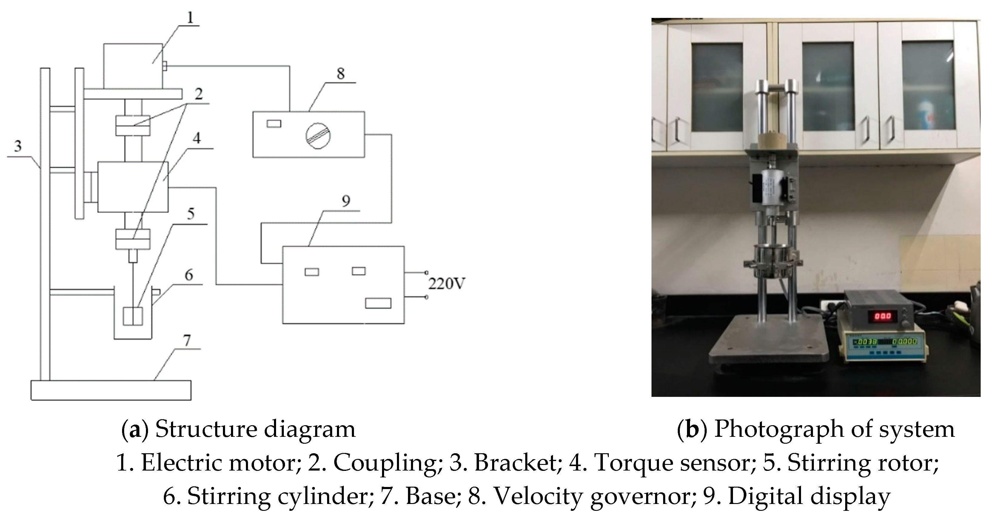
Figure 1. (a) Schematic and (b) photograph of a rheometer for high-concentration coal gangue backfill slurry (HCGS rheometer) structure.
Processes 08 00284 g001
Figure 2. Schematic diagram for the rotor rotation.
Processes 08 00284 g002
Figure 3. Rheological parameter testing process.
Processes 08 00284 g003
Figure 4. The particle size distribution of fly ash.
Processes 08 00284 g004
Figure 5. M Ω curve of the slurry with concentrations of 76%–79% (Group A).
Processes 08 00284 g005
Figure 6. M Ω curve of slurry with 15%–30% fly ash content (Group B).
Processes 08 00284 g006
Table 1. Granular composition of coal gangue.
Particle Size (mm)20–1010–55–2.52.5–1.251.25–0.630.63–0.310.31–0.16<0.16
Content (%)18231712.595.55.59.5
Table 2. M Ω relationship.
GroupsVariable M Ω   Fitted   Formulas ab
A. Mass concentration (%)76 M = 4.25 × 10⁻⁴ Ω + 8.88 × 10−34.25 × 10−48.88 × 10⁻³
77 M = 4.48 × 10⁻⁴ Ω + 9.50 × 10−34.48 × 10−49.50 × 10⁻³
78 M = 4.75 × 10⁻⁴ Ω + 1.15 × 10−34.75 × 10−41.15 × 10⁻³
79 M = 5.07 × 10⁻⁴ Ω + 1.64 × 10−35.07 × 10−41.64× 10⁻³
B. Fly ash content (%)15 M = 4.32 × 10⁻⁴ Ω + 1.49 × 10−34.32 × 10−41.49 × 10⁻³
20 M = 4.53 × 10⁻⁴ Ω + 1.31 × 10−34.53 × 10−41.31 × 10⁻³
25 M = 4.75 × 10⁻⁴ Ω + 1.15 × 10−34.75 × 10−41.15 × 10⁻³
30 M = 5.42 × 10⁻⁴ Ω + 1.54 × 10−35.42 × 10−41.54 × 10⁻³
Table 3. Rheological parameter values of the slurry.
Mass Concentration (%)76777879
τ 0 (Pa)54.057.869.999.7
η (Pa·s)2.372.502.652.83
Fly Ash Content (%)15202530
τ 0 (Pa)90.979.569.993.5
η (Pa·s)2.412.522.653.02
Table 4. Reynolds number and critical Reynolds number of the slurry.
Mass Concentration76%77%78%79%
D = 0.1 m Re 160152143134
Re c 2662267027502967
D = 0.2 m Re 321304287269
Re c 3217323333893809
Table 5. Friction resistance coefficients under different pipe diameters.
Inner   Diameter   D
(m)
Slurry   Velocity   U
(m/s)
Frictional   Resistance   Coefficients   f (kPa/m)
Mass Concentration 77%Mass Concentration 78%
0.131.8811.2712.30
0.141.628.819.67
0.151.427.107.84
0.161.245.806.44