Process Drive Sizing Methodology and Multi-Level Modeling Linking MATLAB® and Aspen Plus® Environment


Abstract
1. Introduction
- First, it presents a robust method for optimal process drive sizing and integration considering all relevant factors affecting the design, while the method is suitable for operational optimization as well;
- Second, both the process-side and steam-side are modeled using Aspen Plus® and MATLAB® linking, which is a novel and promising approach for complex systems’ operation analysis and optimization purposes.
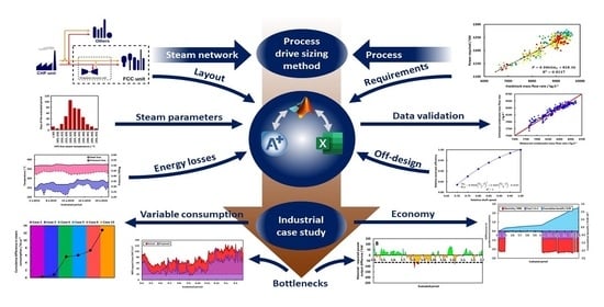
2. Process Drive Sizing Method
2.1. Equipment Operation Assessment and Modeling
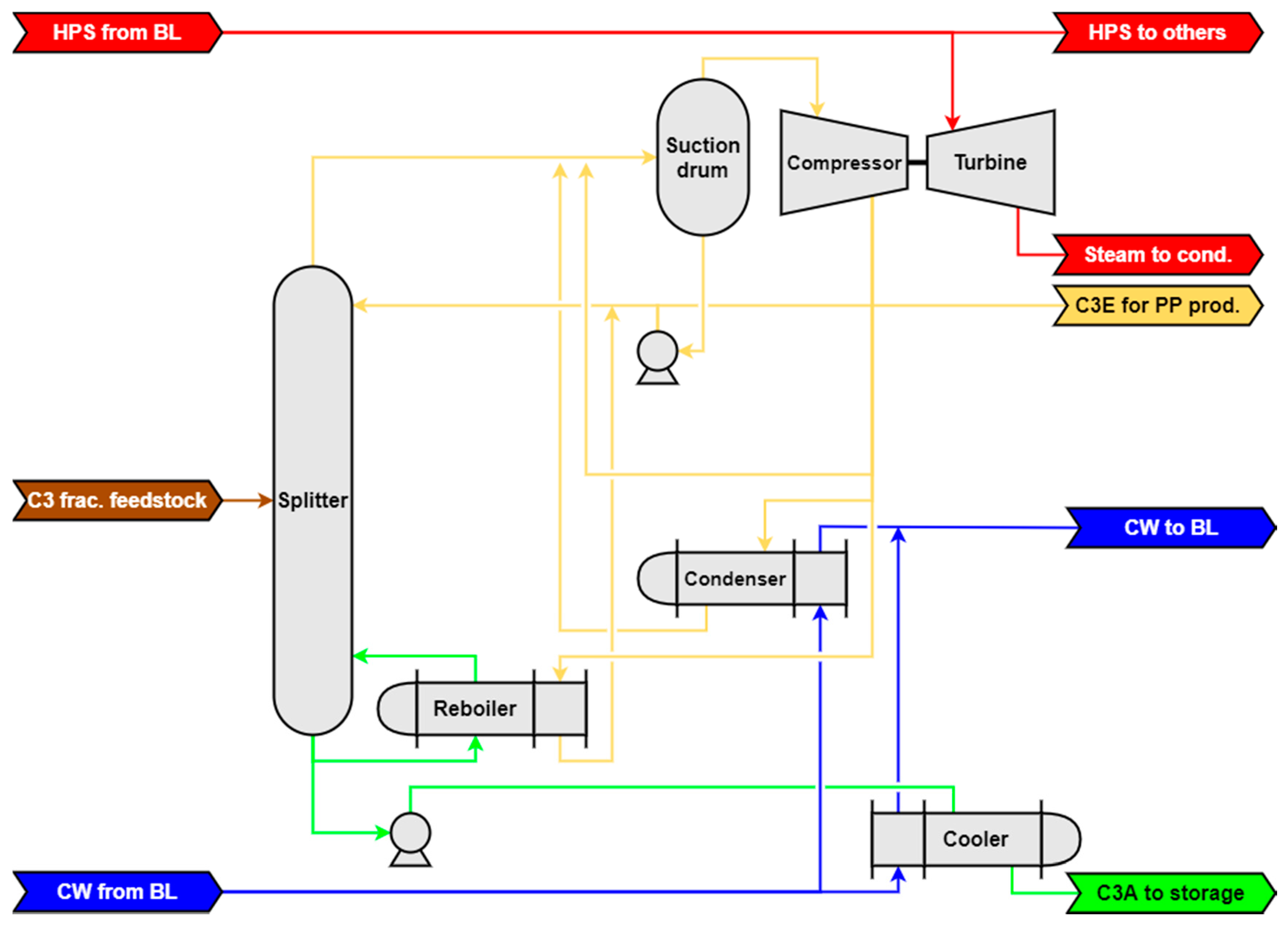
2.1.1. Heat Pump-Assisted C3 Fraction Splitting
- Due to simplicity of the mixture being distilled, an equilibrium model using Murphree tray efficiency was chosen;
- Because the operating temperature of the column (25–35 °C) was similar to ambient temperature, heat loss from the system was neglected;
- Technical details regarding the number of column trays and the position of the feed stage; exchanger areas, overall heat transfer coefficients, and logarithmic mean temperature differences; and compressor and condensing turbine characteristics were taken from technical documentation provided by the manufacturer.
2.1.2. Compressor Operation
2.1.3. Process Drive Operation
2.1.4. Steam Network
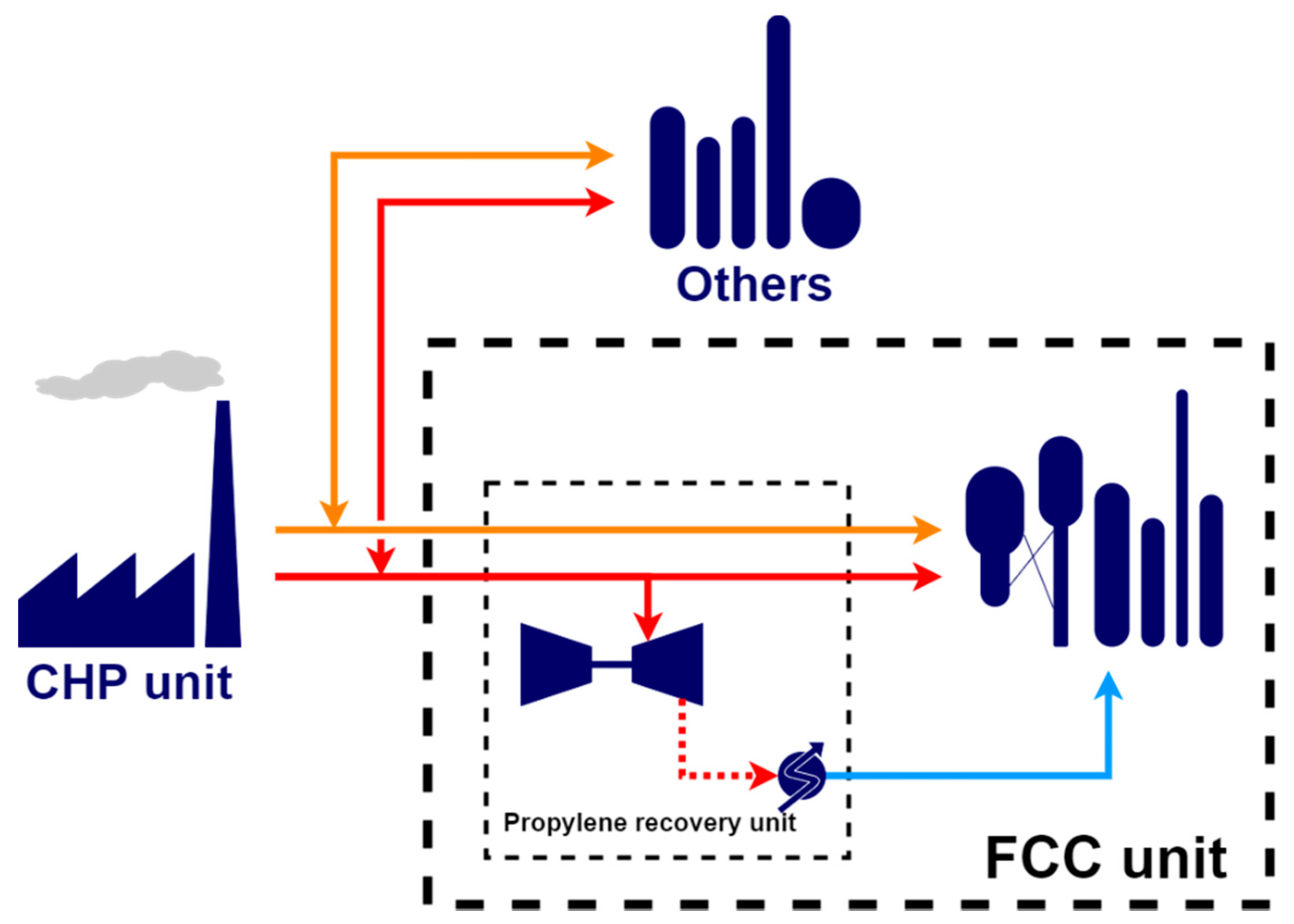
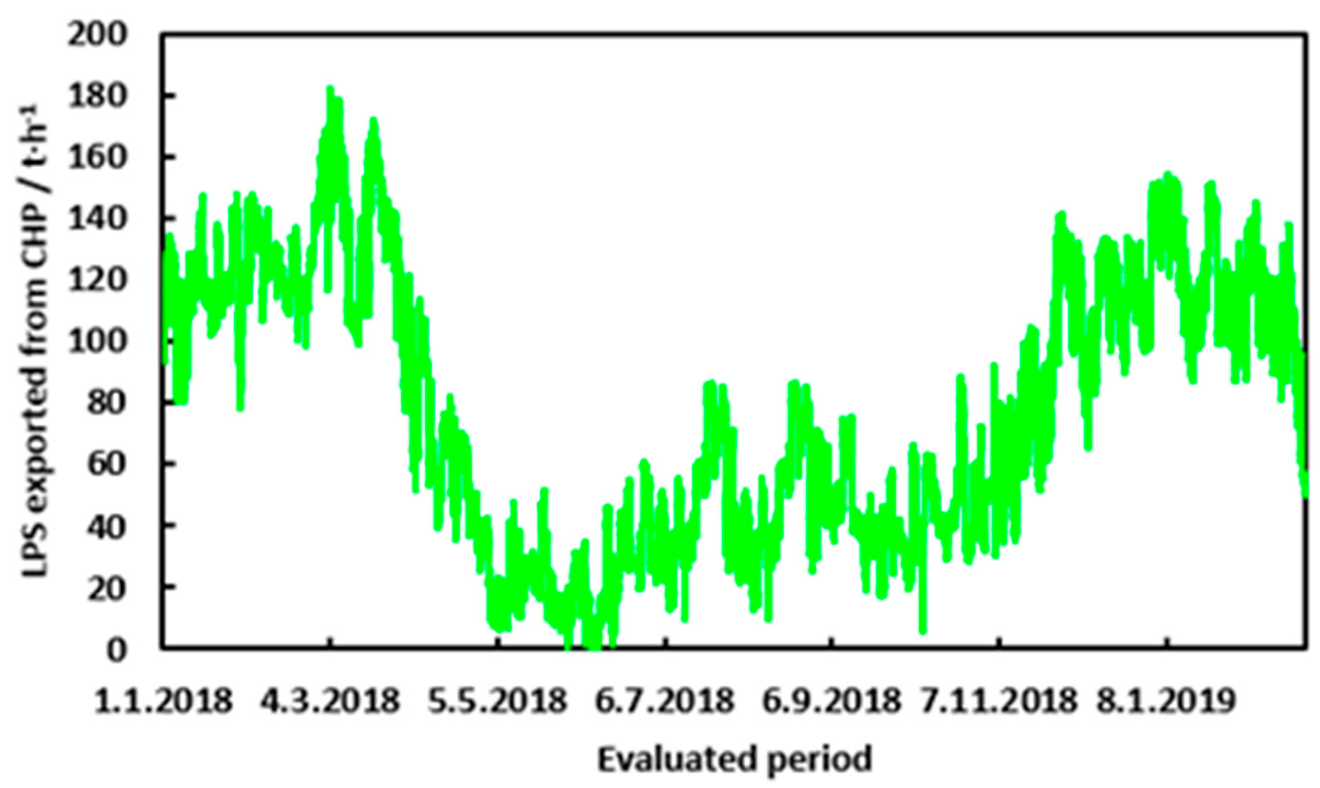
2.1.5. Combined Heat and Power Unit (CHP) as Marginal Steam Source
2.2. Data Processing
2.2.1. Measured Data
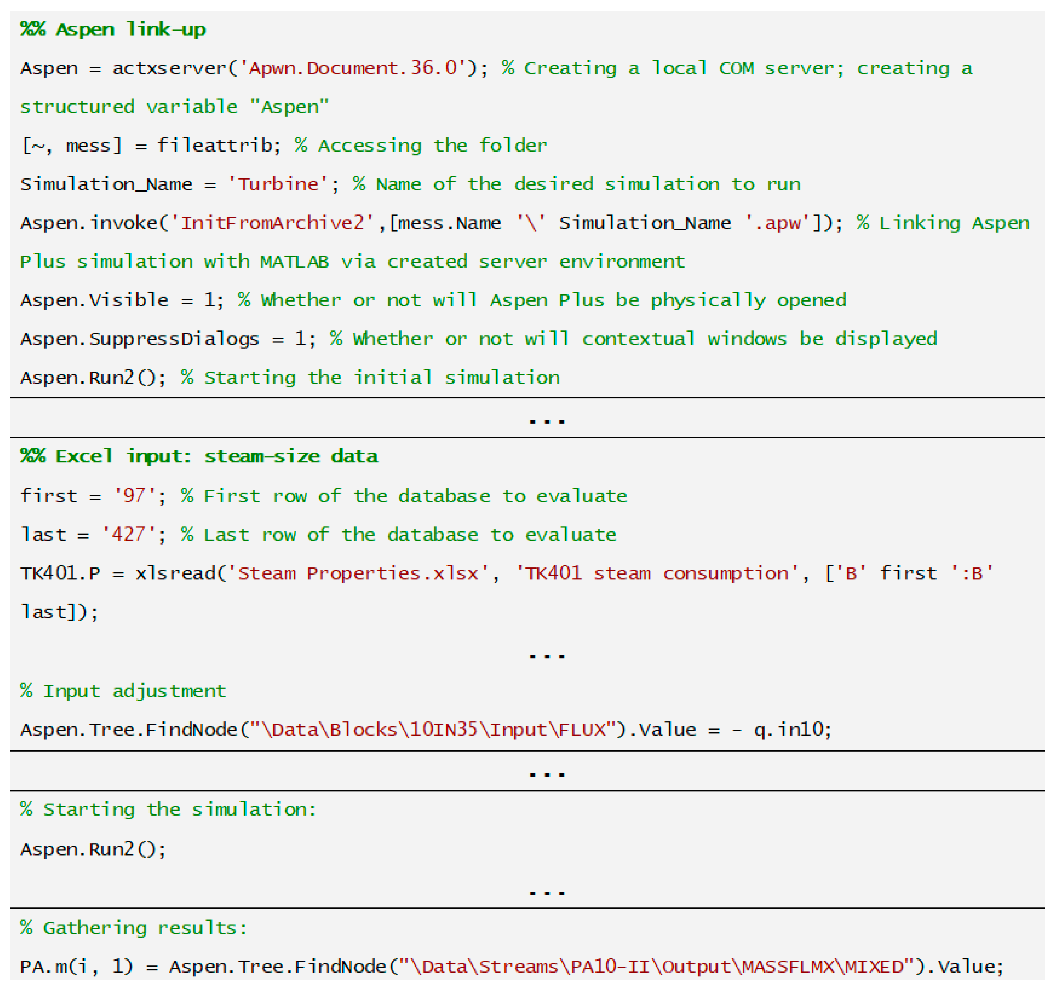
2.2.2. Aspen–MATLAB Linking
- to connect inputs and results of Aspen Plus® simulations to other applications;
- to manipulate (create, reconnect, delete, etc.) Aspen Plus® objects;
- to control the Aspen Plus® user interface (handle events, suppress dialog boxes, disable user interface features, etc.);
- to control a simulation (run, stop, reinitialize, etc.).
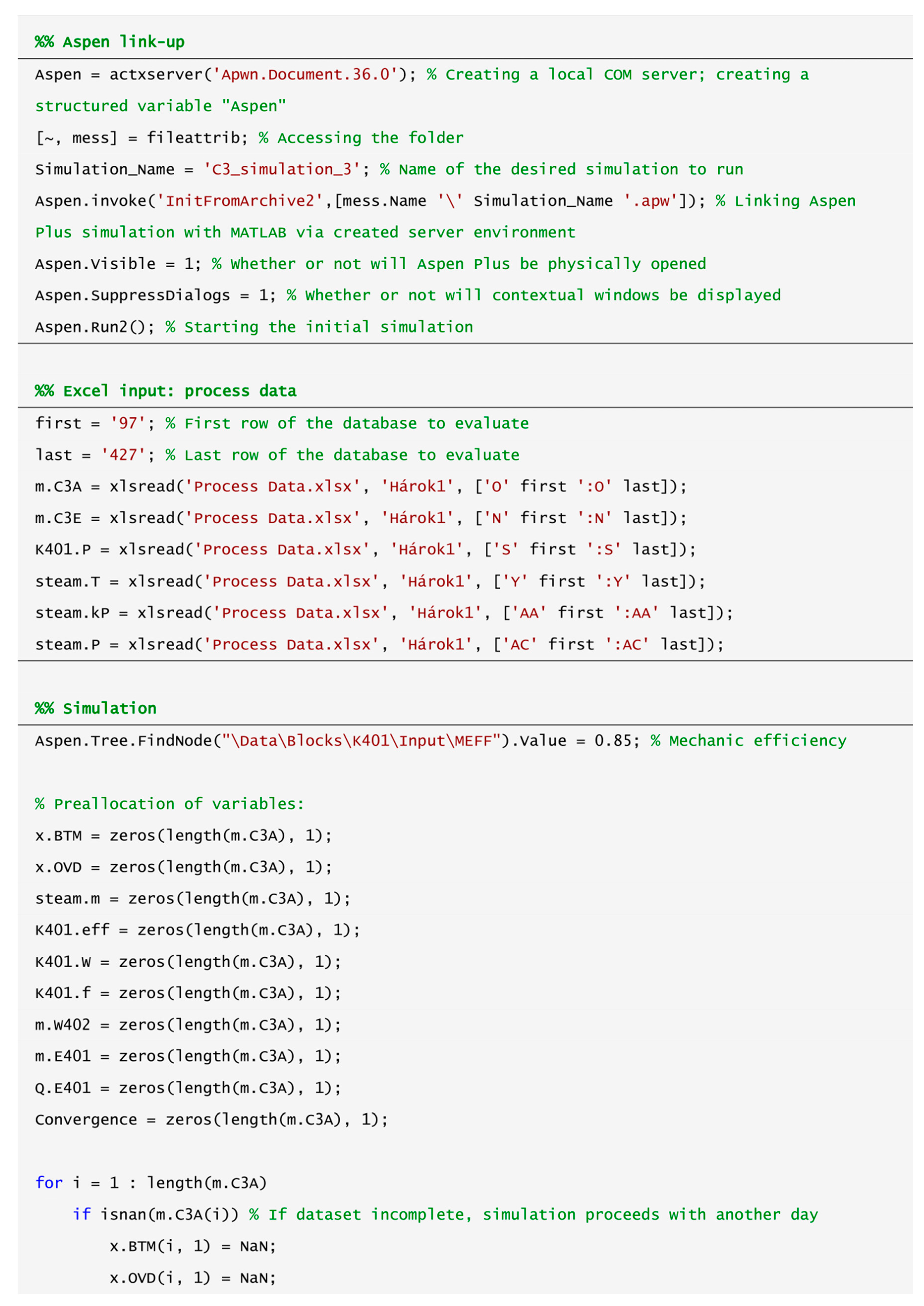
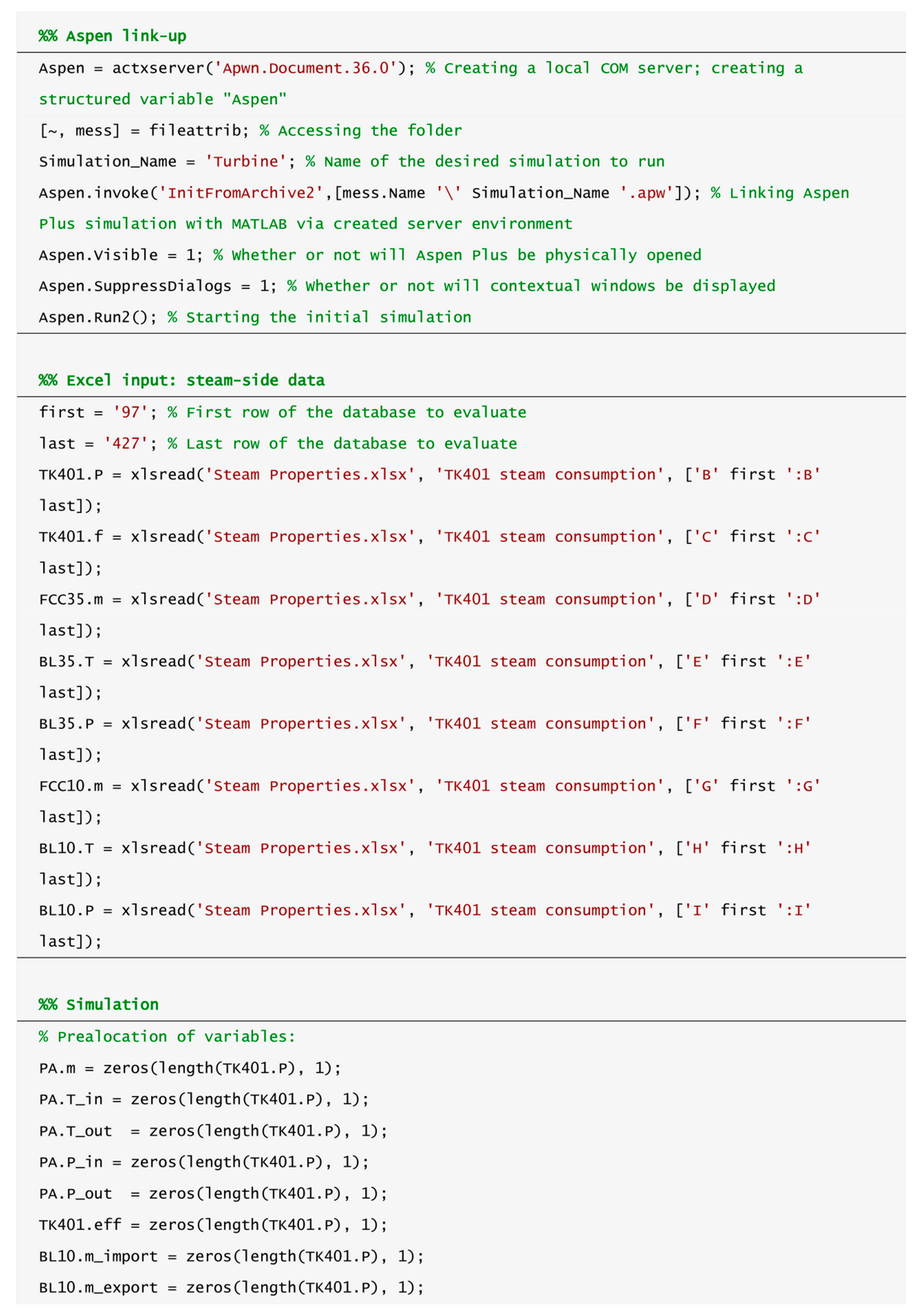
- First, a local ActiveX server is created where the component object model is situated using the inbuilt function “actxserver”. The syntax is as follows: var = actxserver(ProgID), where var is a structured variable used to access the server and ProgID is the program identifier. The program identifier for Aspen Plus® documents is “Apwn.Document.X” where X depends on the Aspen Plus® version: 34.0 for V8.8, 35.0 for V9.0, and 36.0 for V10.0 (e.g., “Apwn.Document.36.0” for Aspen Plus® V10);
- After the server creation, the whole system is initialized as shown in Figure 3. There are three initialization methods depending on the format of the simulation: “InitFromArchive2” (for use with .bkp and .apw archive files), “InitFromTemplate2” (for use with templates), and “InitFromFile2” (for use with .apwn compound files). No difference has been observed in their performance, though .bkp files are generally the smallest in size and thus recommended. As with other MATLAB® scripts, all files have to be located in the same folder;
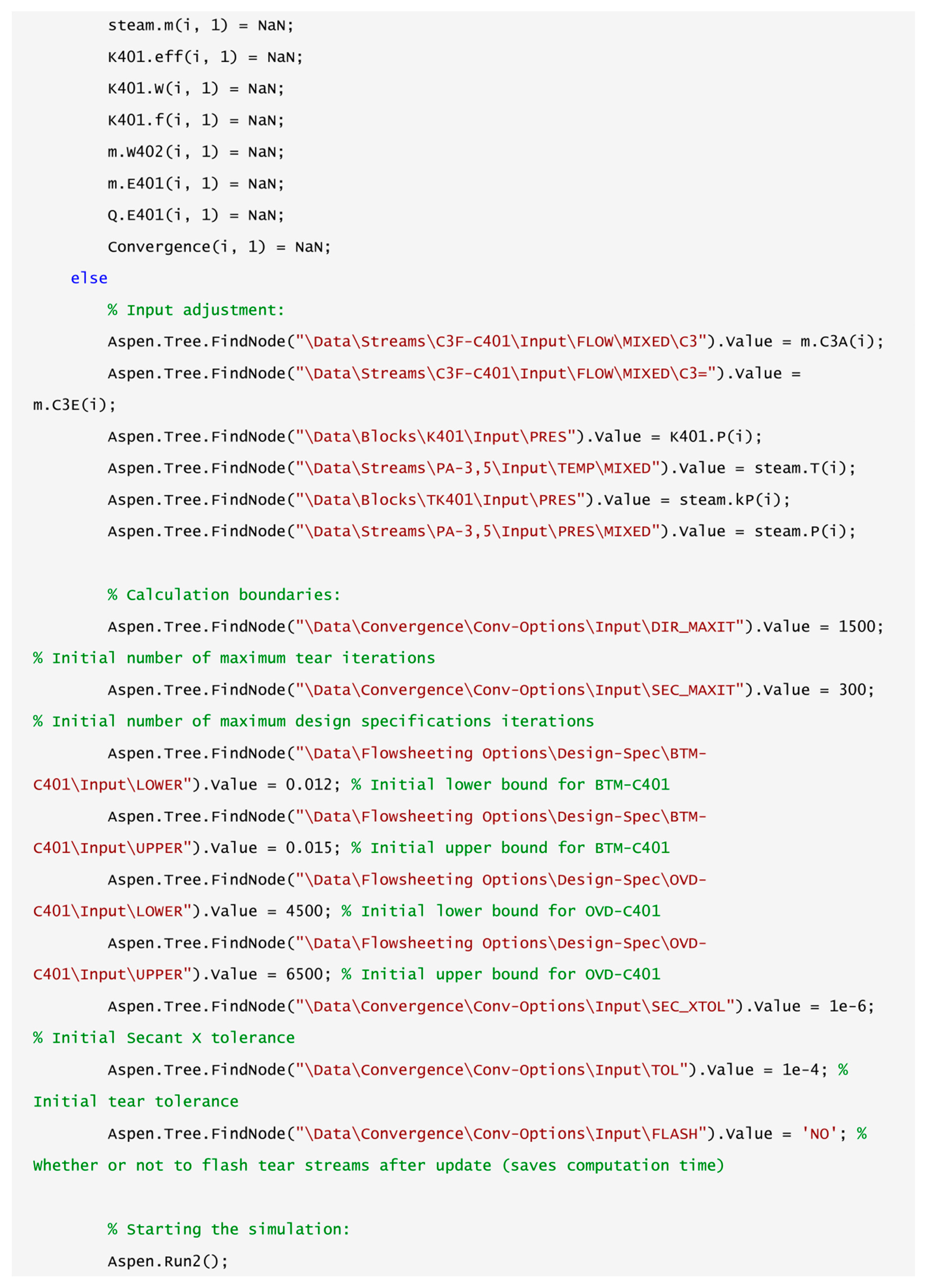
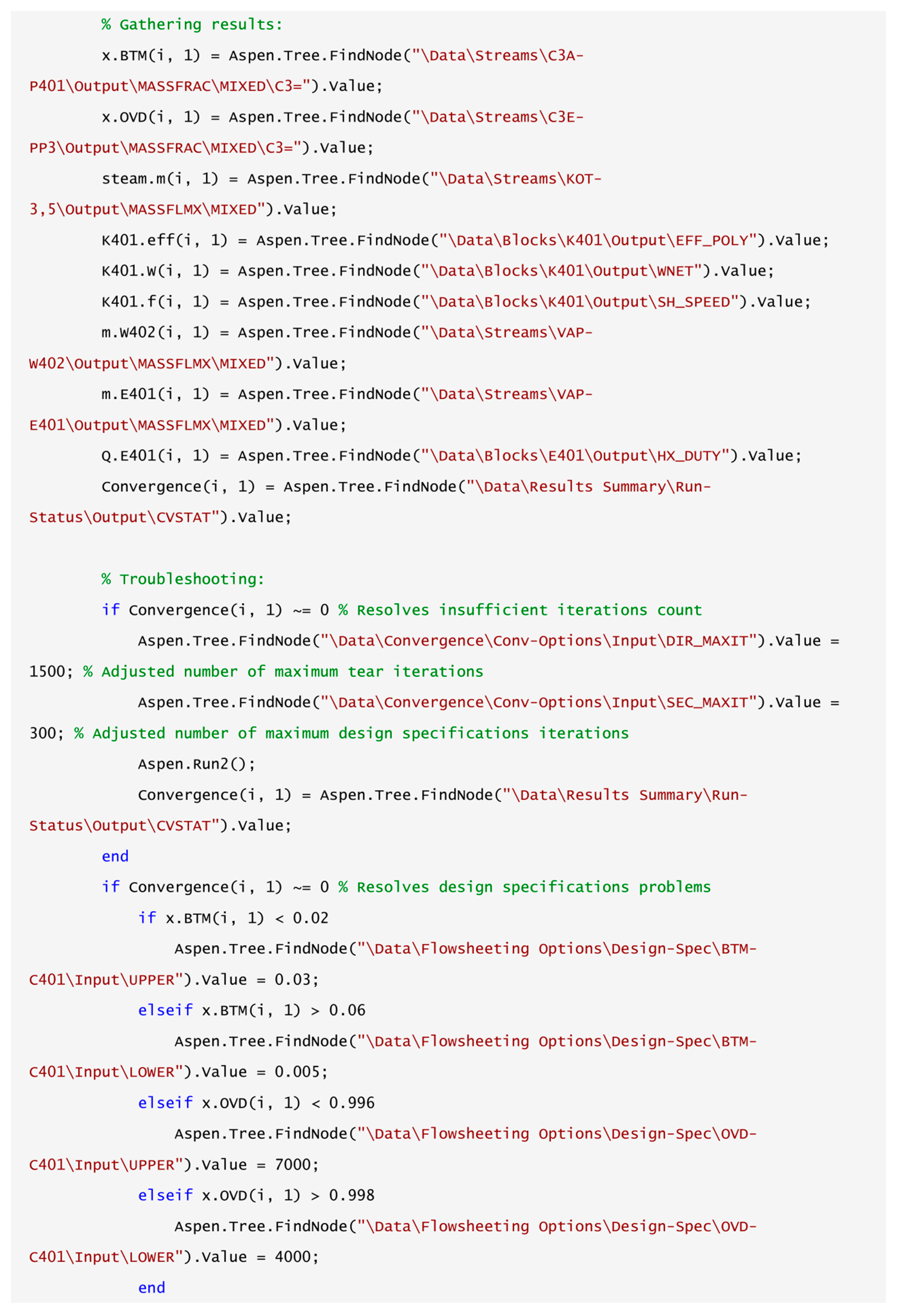
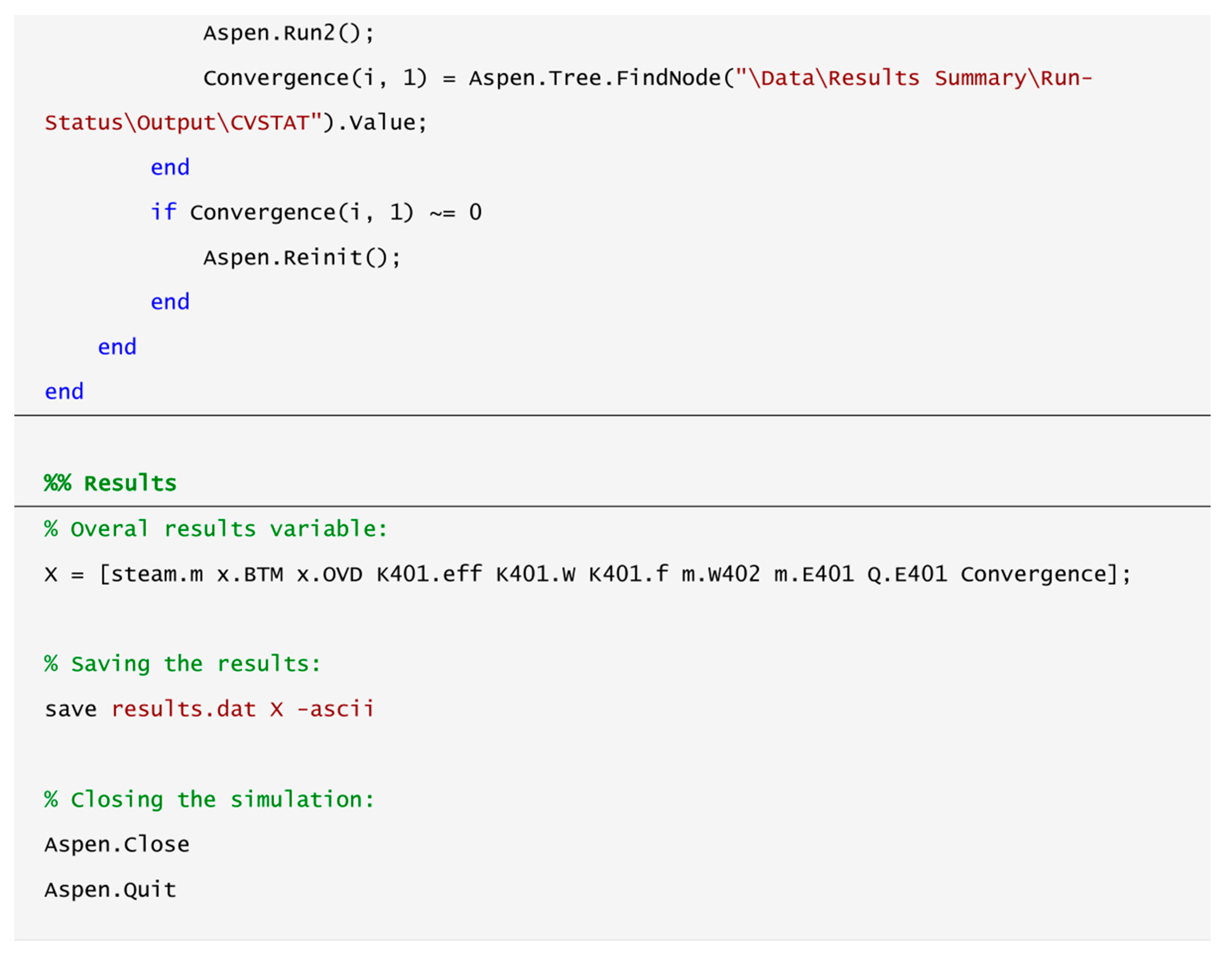
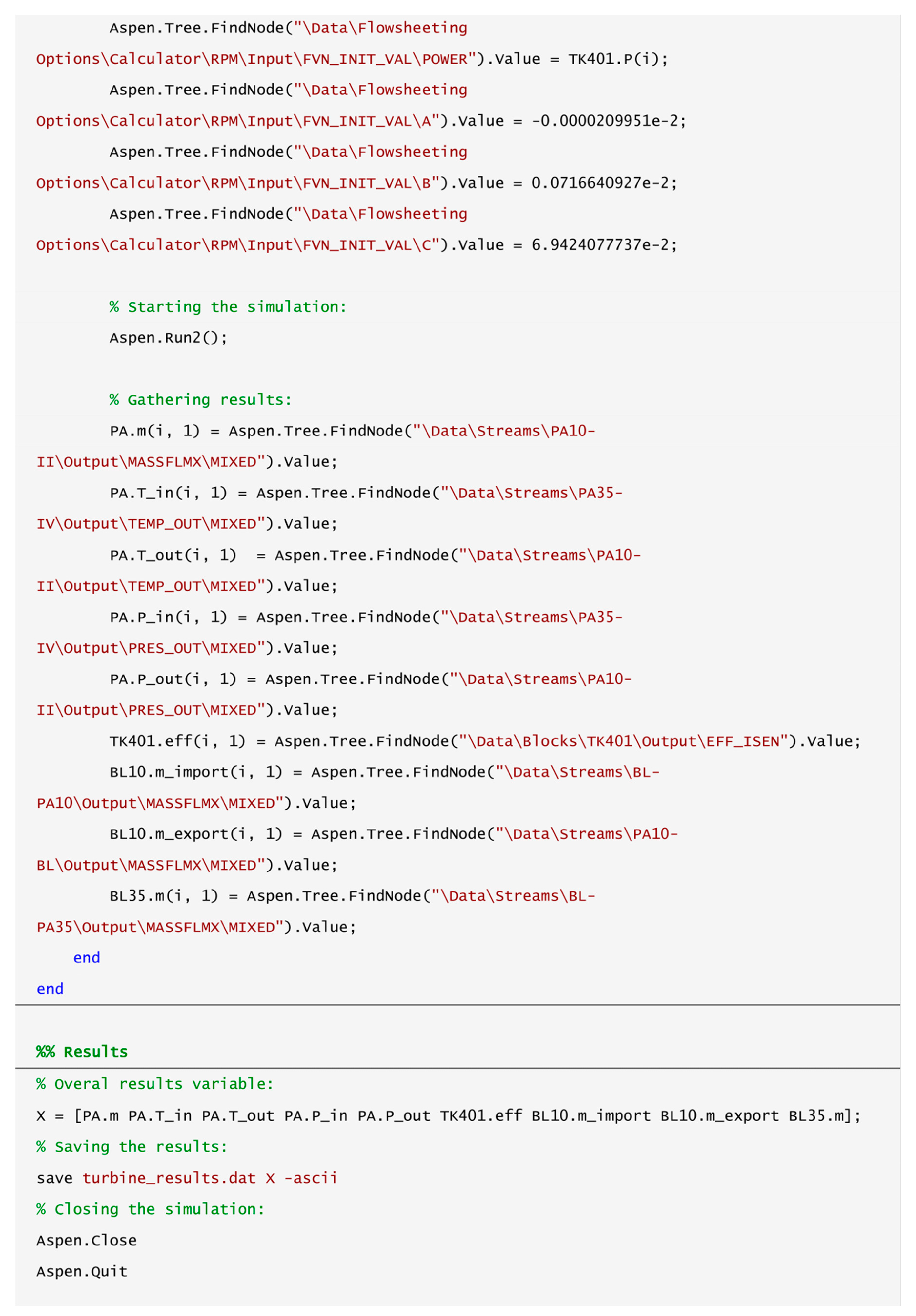
- From this point on, the Aspen–MATLAB® link is ready to use. To access results, manage inputs, and control the simulation and/or the user interface, dot notations are used. Examples of the syntax for various commands are given below:
- Simulation controlSyntax: var.command (e.g., var.Run2, var.Reinit, …)
- User interface controlSyntax: var.attribute = value (e.g., var.Visible = 1, …)
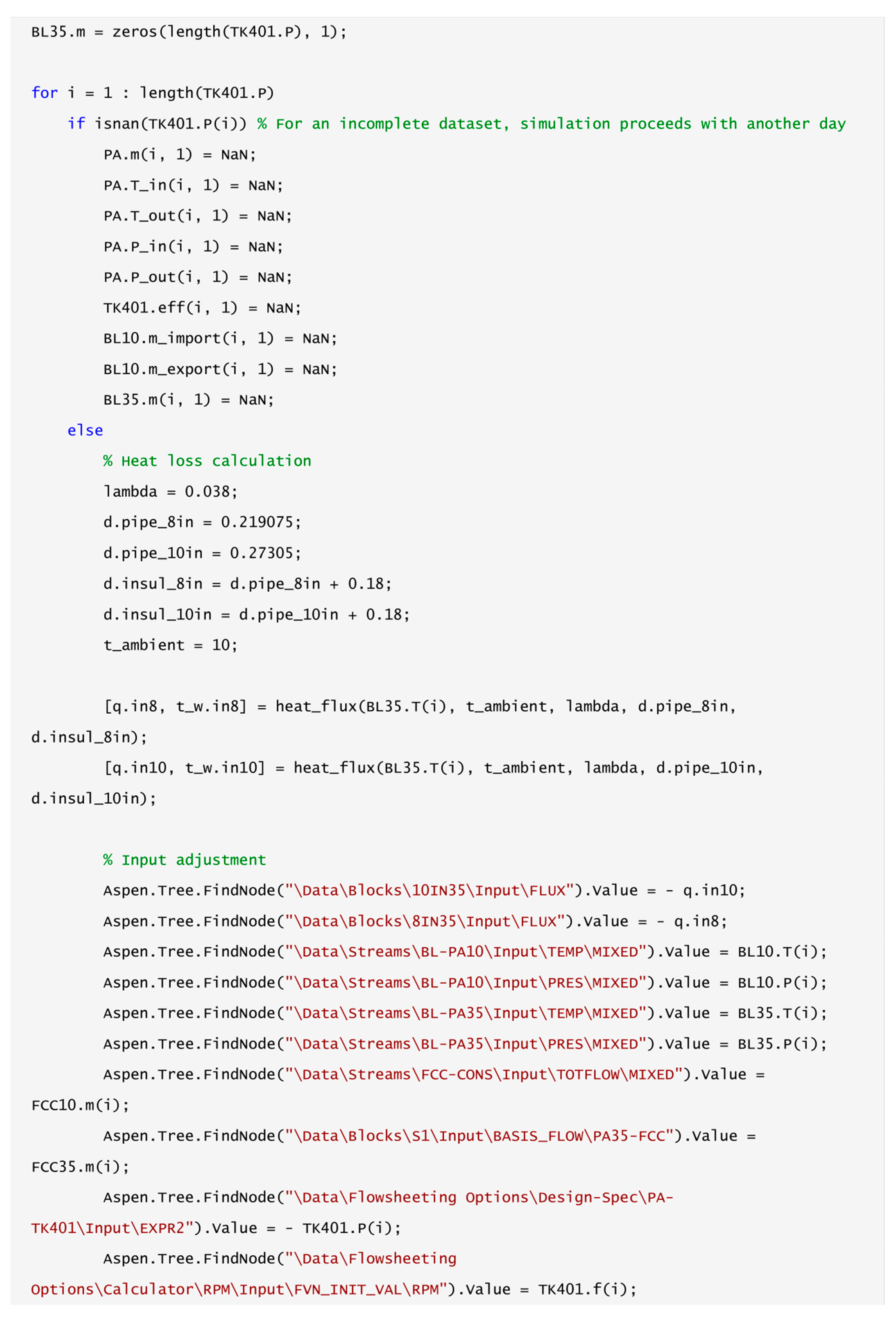
- Input alterationSyntax: var.Tree.Findnode(path).Value = value_a
- Results gatheringSyntax: value_b = var.Tree.Findnode(path).Value
- Prior to launching the simulation, it is sensible to also link MATLAB to Excel for more flexible operation via simple and useful inbuilt functions “xlsread” and “xlswrite” enabling reading and writing data from and to the Excel spreadsheet, respectively, without the need for opening the data file manually. An example can be seen in Figure 3.
3. Industrial Case Study
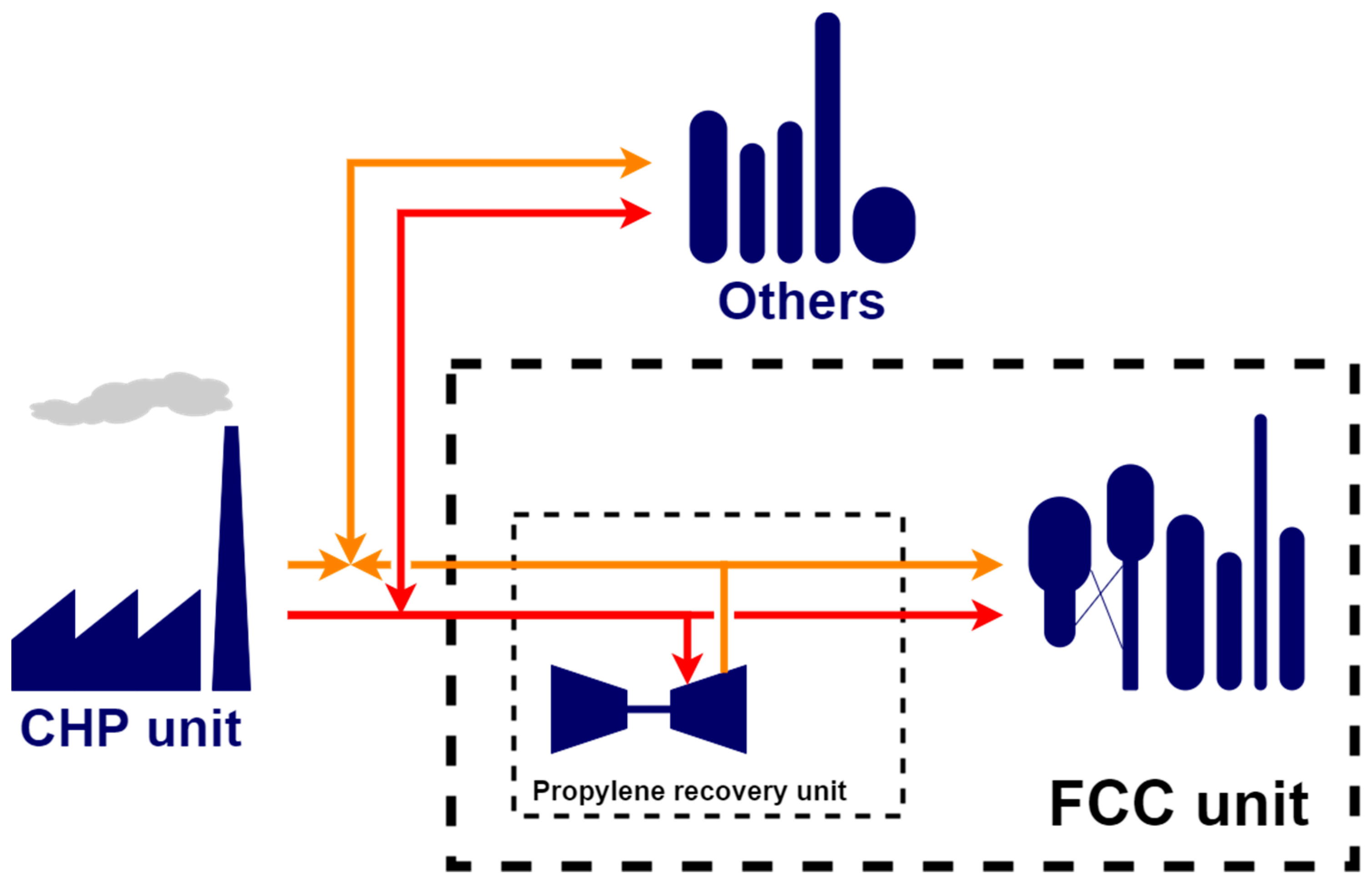
3.1. System Description
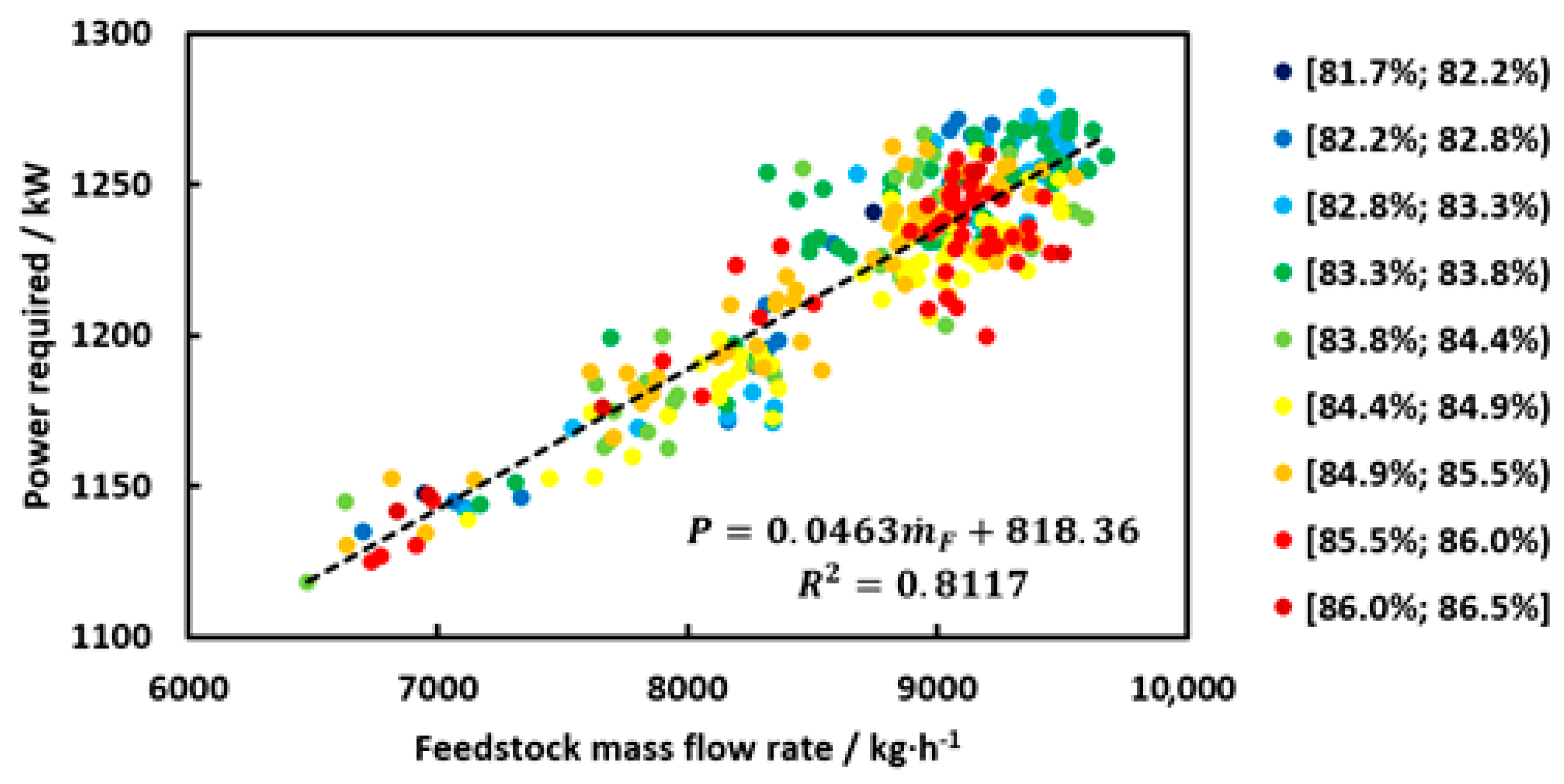
- The unit’s feedstock flow rate was flexible, ranging from 6.5 to 9.7 t/h;
- Feedstock quality ranged from 81.7 to 86.5 mass % of propylene;
- Turbine condensate pump was by-pass protected.
- Maximal unit throughput was 10 t/h of the propane–propylene fraction;
- Maximal compressor power at the coupling is 1250 kW.
3.2. Proposed Change in Steam Drive Type
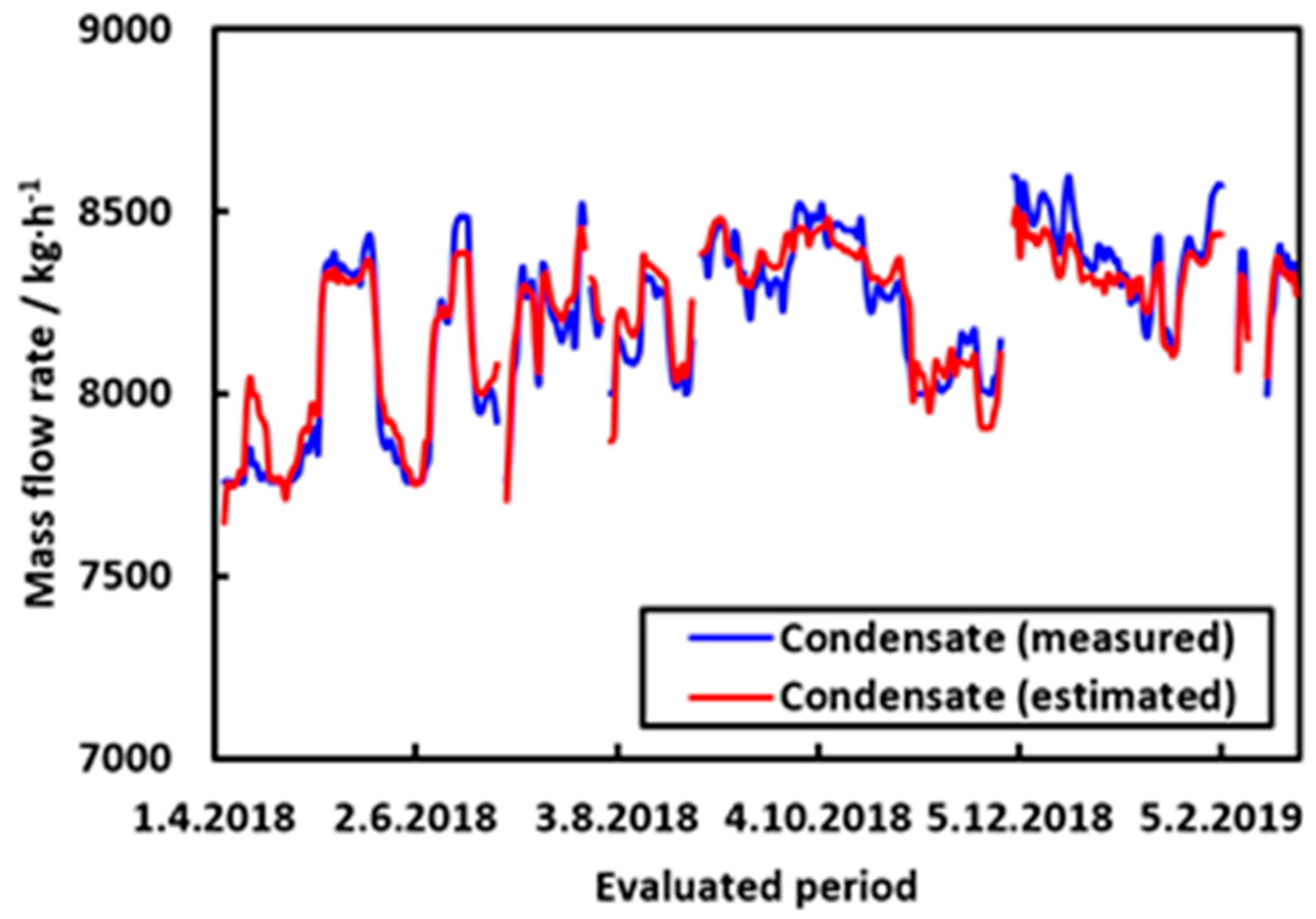
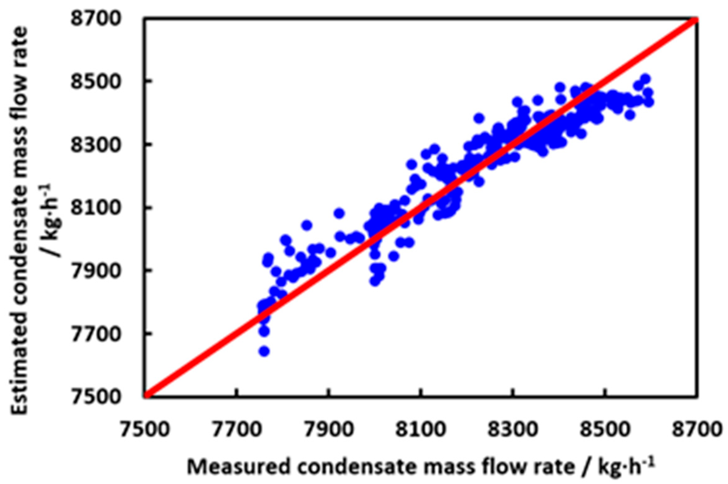
3.3. Key System Analysis and Model Verification
- Obtain the process side characteristics—to evaluate the maximal power requirements and predict the process behavior in case of insufficient power supply as well as the daily performance;
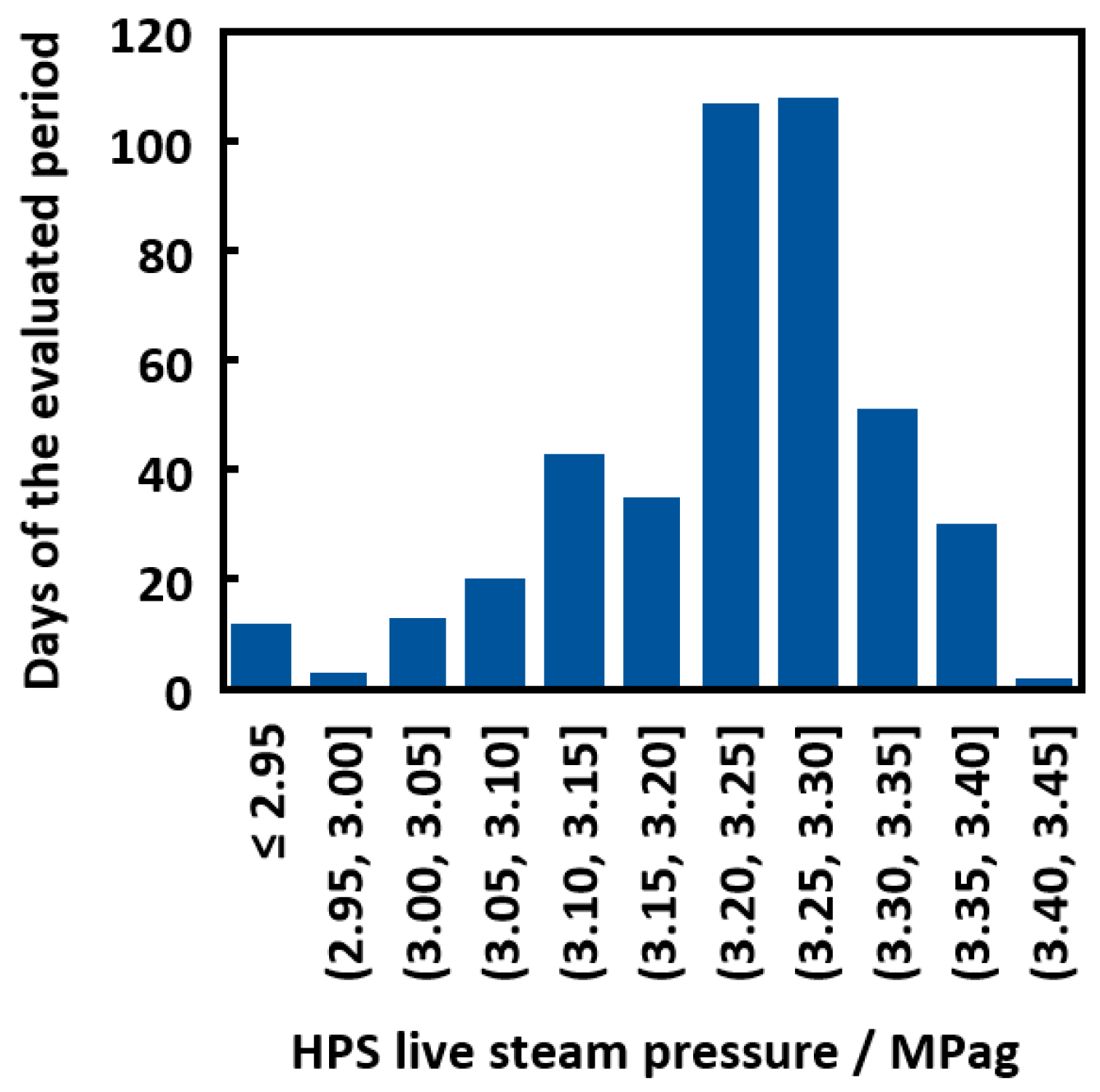
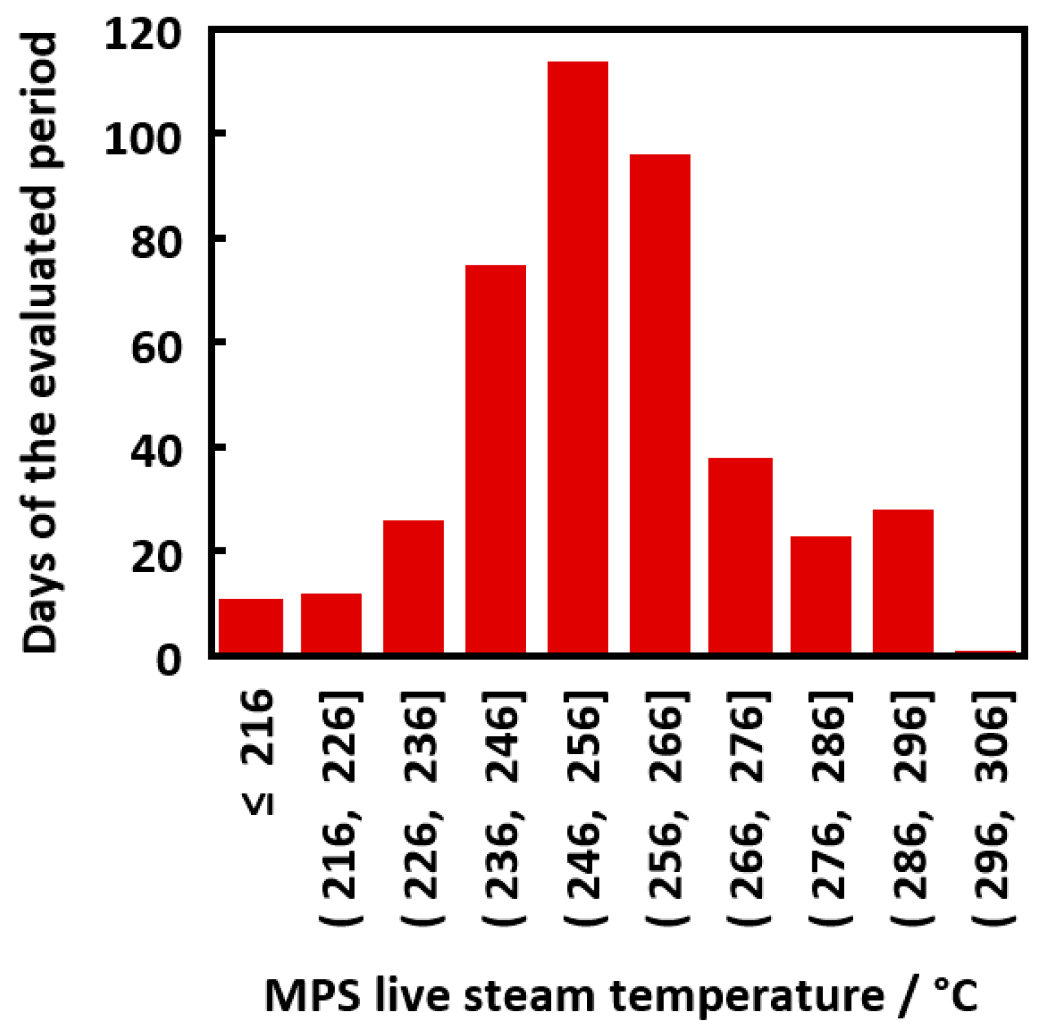
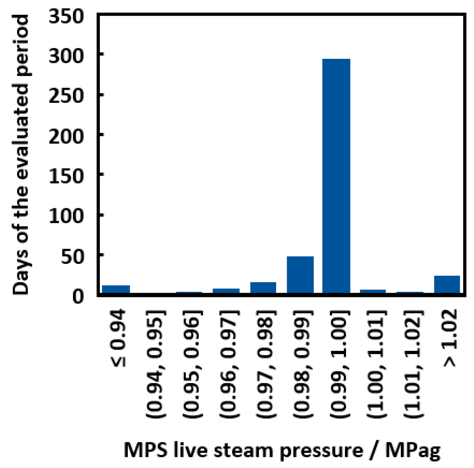
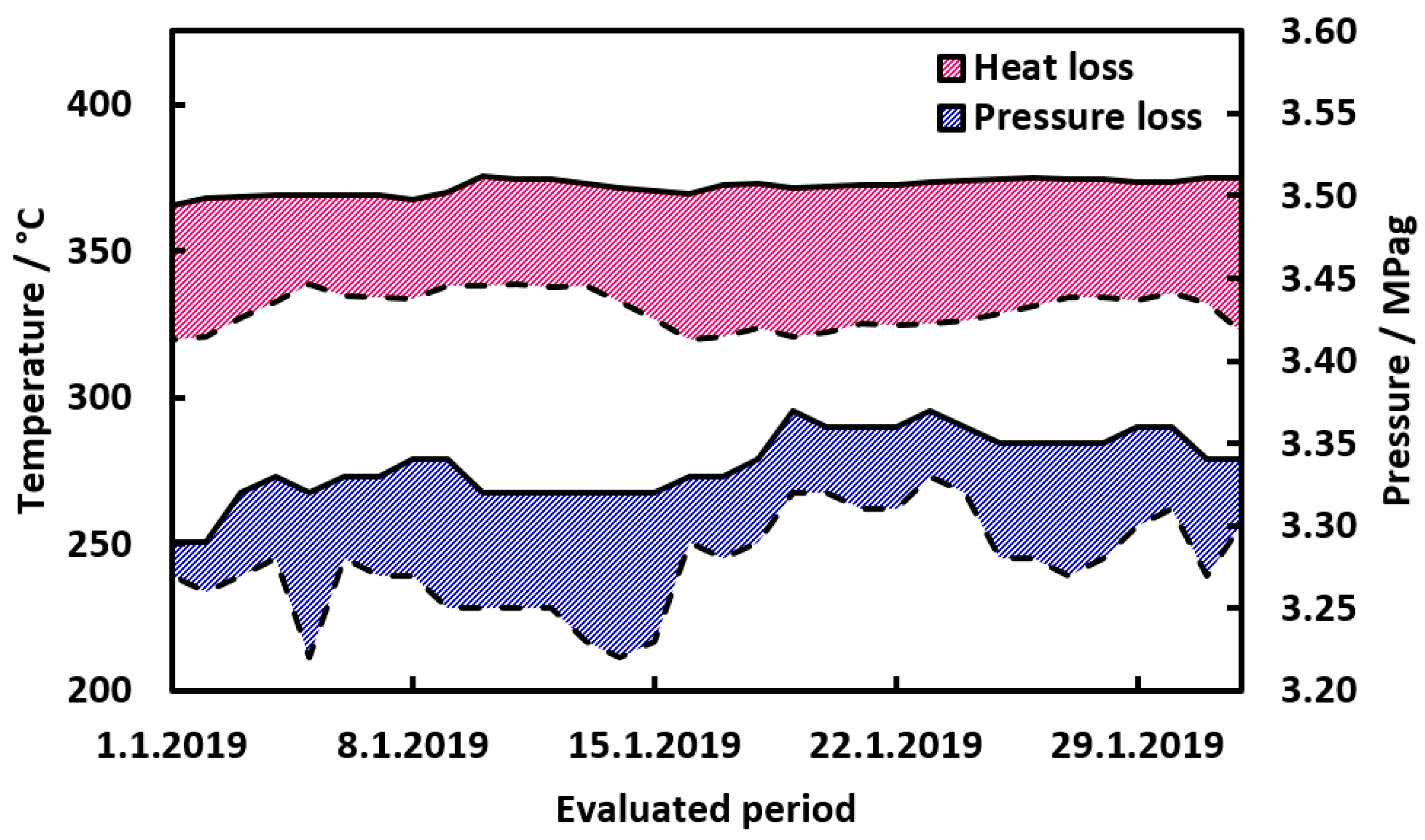
- Map fluctuations in the steam network as to find the most appropriate design parameters for a new steam drive;
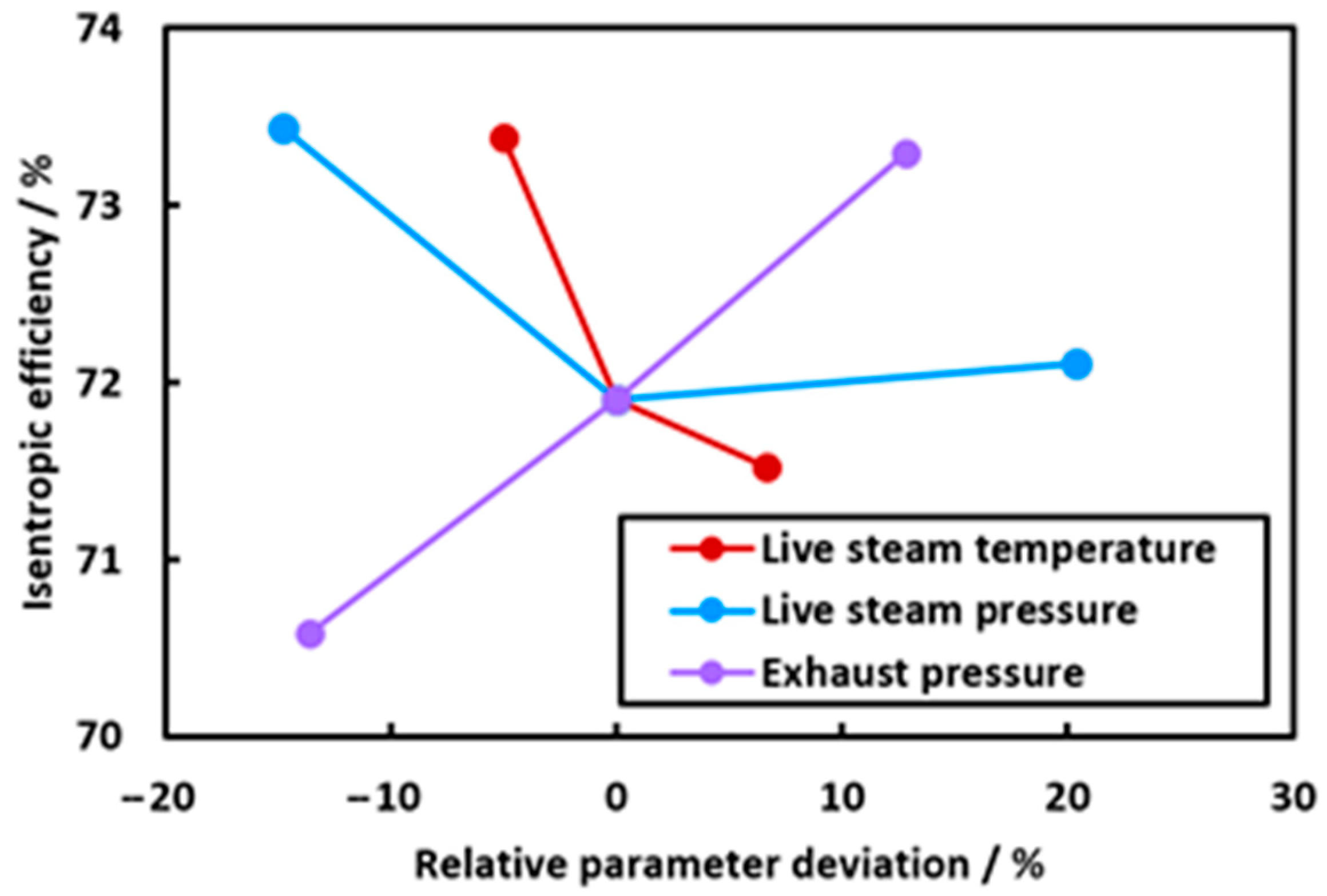
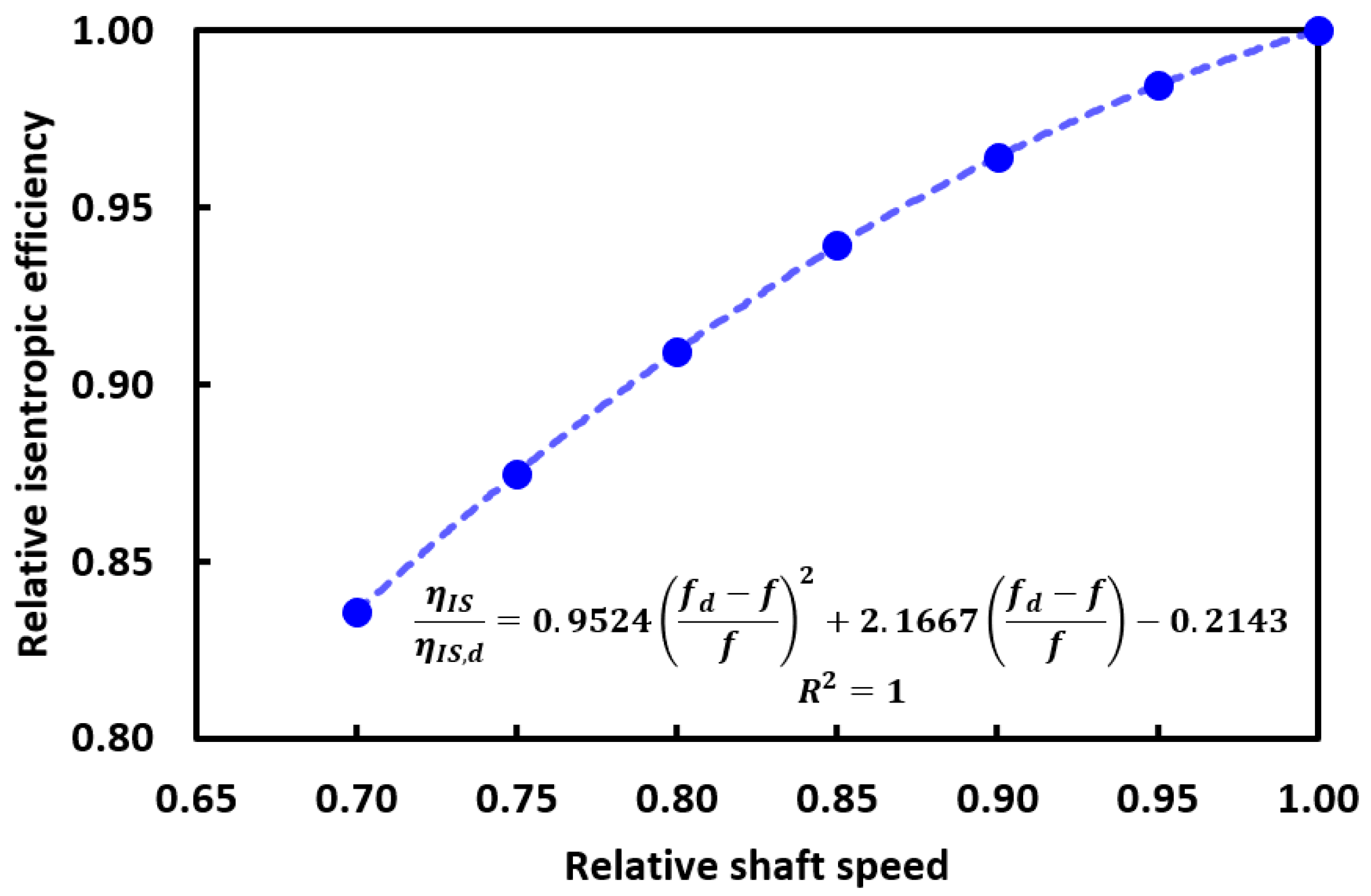
- Understand the effects of the process side (shaft speed and power requirements) and steam side (live steam pressure, live steam temperature, and exhaust pressure) parameters on turbine efficiency.
3.4. Variable Approaches in Steam Drive Design
4. Results and Discussion
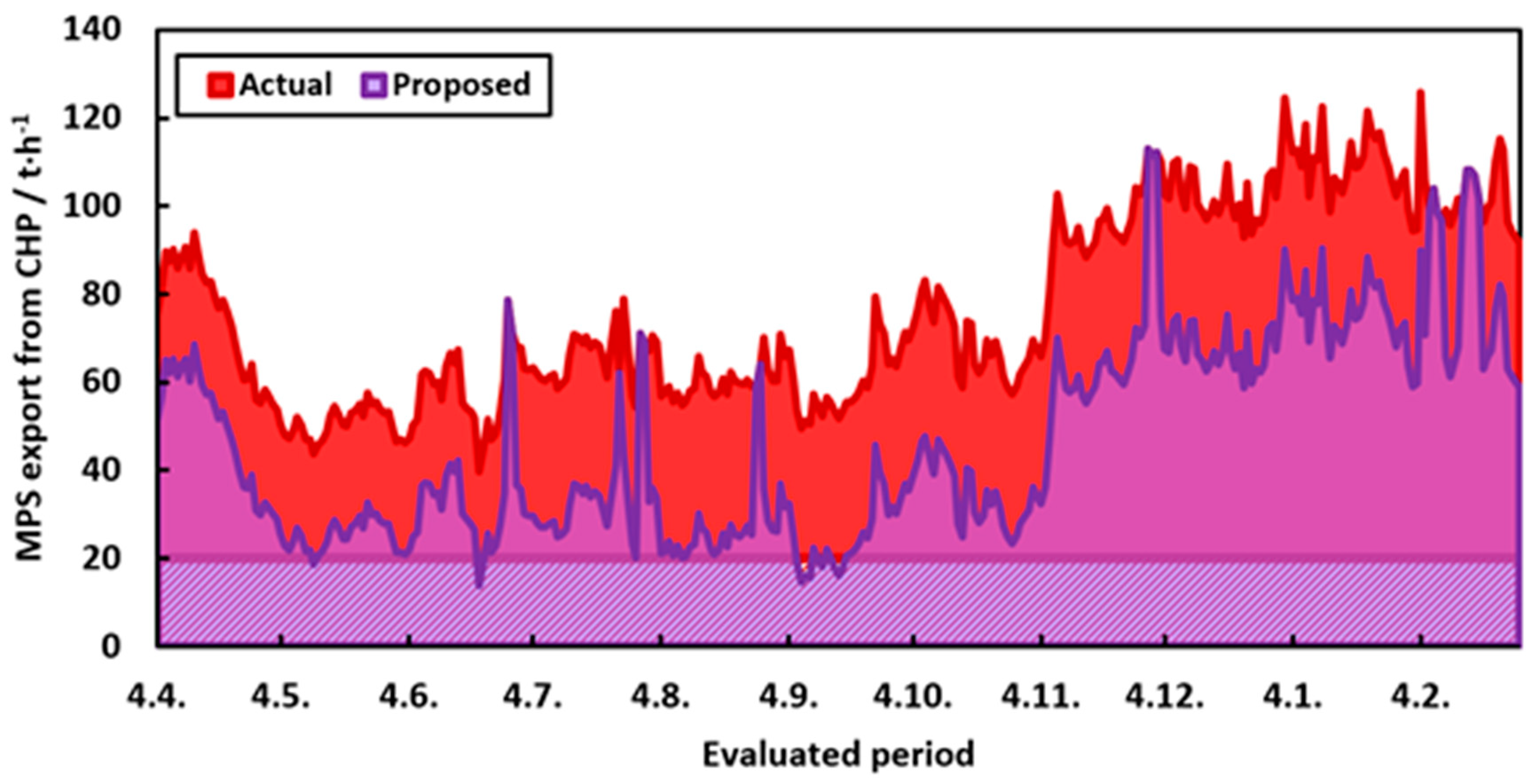
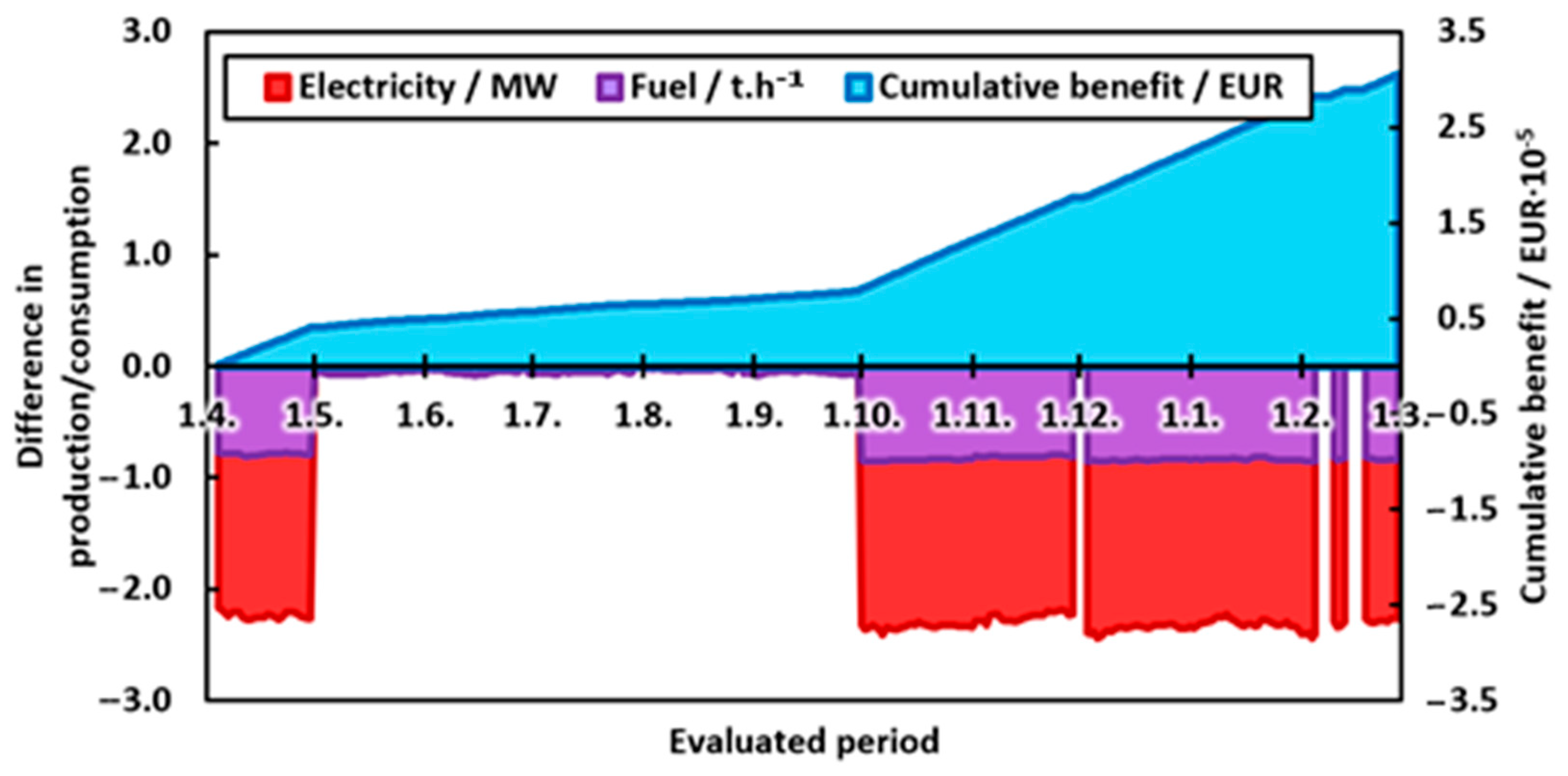
- In colder months (October to April), fuel is saved, and CO2 emissions are reduced. Backpressure power production in the CHP is also reduced;
- In warmer months (May to September), the reduction in the CHP backpressure power production is compensated by an increase in the condensing production which keeps the total power output of the CHP unchanged. The resulting change in fuel consumption and in CO2 emissions production is determined by the difference between: (a) Marginal condensing power production efficiency of the CHP and, (b) the condensing mechanical power production in the replaced condensing steam drive.
- Average thermal efficiency of the CHP is 85%, determined as the ratio of the enthalpy in exported steam to the fuel lower heating value;
- Heavy fuel oil combusted in the CHP produces 3.2 tons of CO2 per 1 ton of oil;
- Marginal efficiency of the condensing power production in the CHP is 3 MWh per ton of combusted fuel.
5. Conclusions
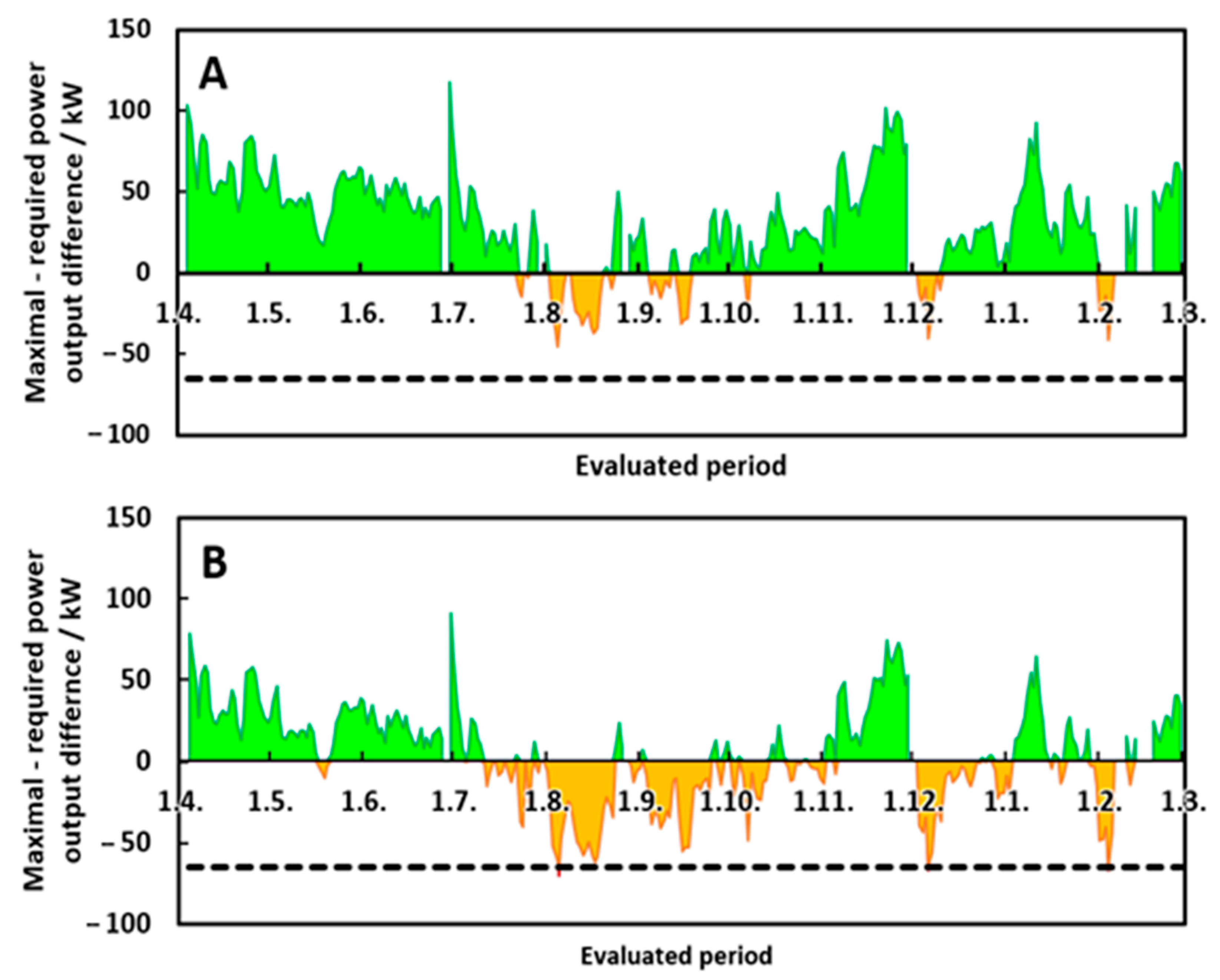
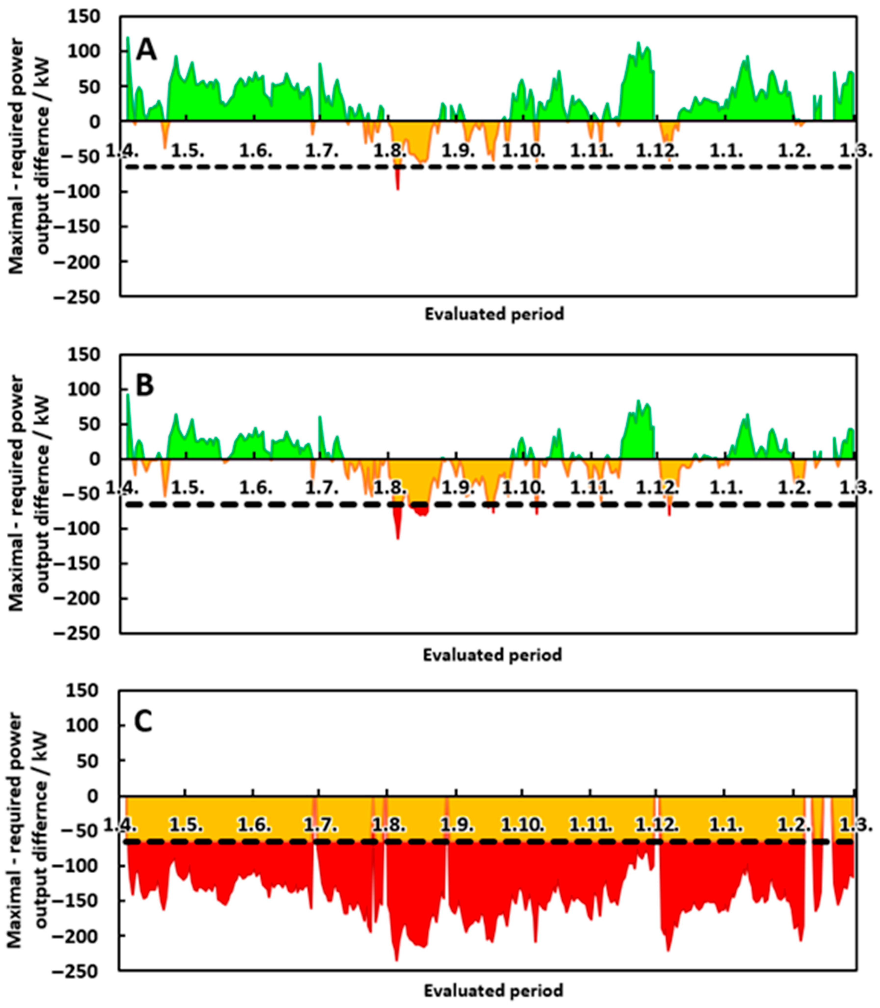
- Steam drive undersizing resulted from lower complexity of the sizing methods;
- Neglecting the variable frequency of the driven equipment, frictional pressure losses, and the steam drive efficiency loss at partial load operation could decrease the ability of the steam drive to provide the power required for the process;
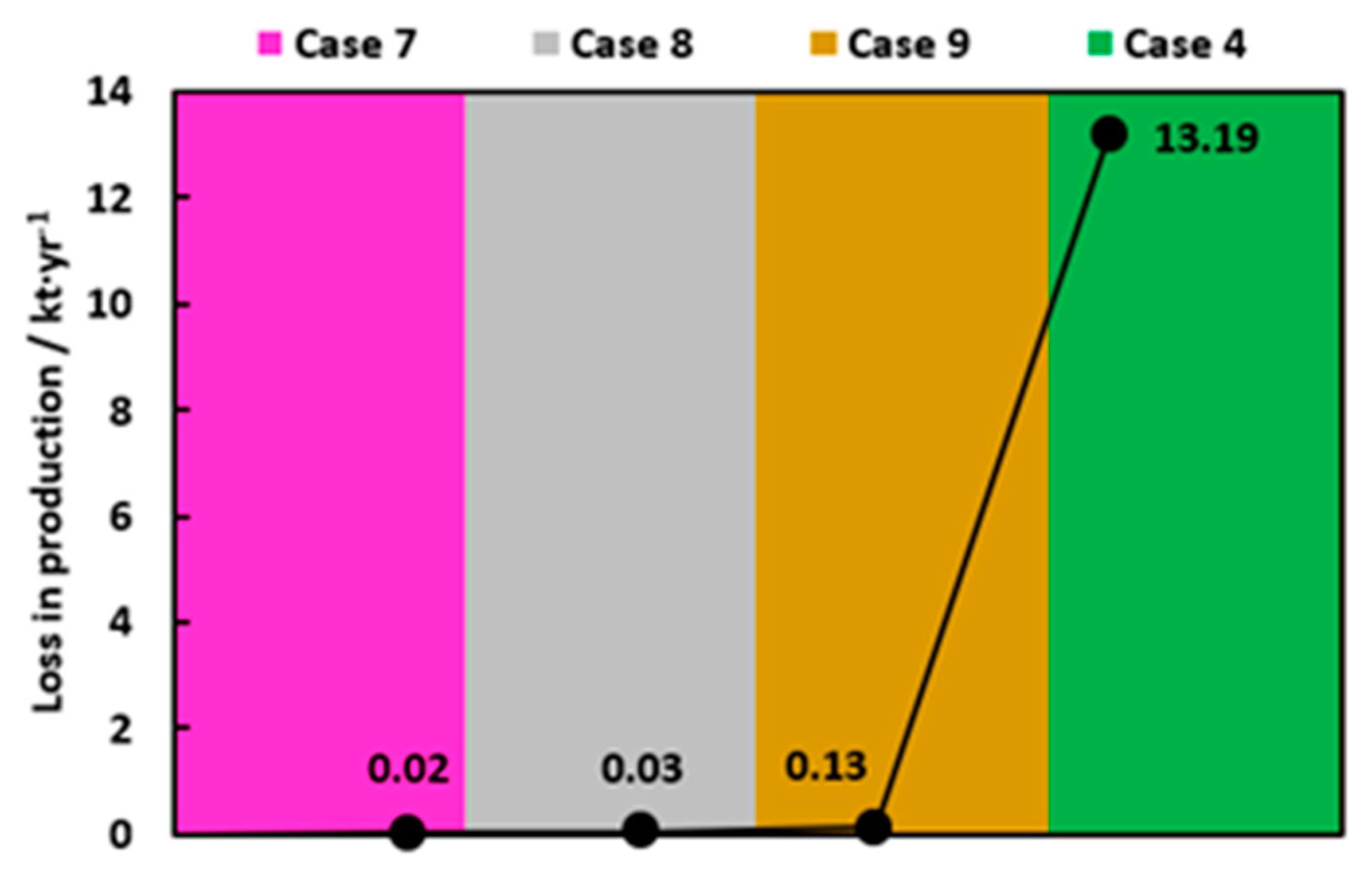
- The simplest sizing method combined with the ten-times-longer steam pipeline led to a C3 fraction splitting capacity decrease of around 20%, which was unacceptable.
Author Contributions
Funding
Conflicts of Interest
Nomenclature
| Abbreviations | |
| BE | balance equations |
| BL | battery limit |
| C3 | propane–propylene mixture |
| C3A | propane |
| C3E | propylene |
| Calc. | calculated |
| CHP | combined heat and power unit |
| COM | component object model |
| Cond. | condenser |
| CW | cooling water |
| FCC | fluid catalytic cracking |
| frac. | fraction |
| HPS | high-pressure steam |
| MPS | middle-pressure steam |
| LPS | low-pressure steam |
| N/A | not applicable |
| NP | not provided |
| PP | polypropylene |
| prod. | production |
| Reg. | calculated based on statistic regression |
| SA | sensitivity analysis |
| SS | saturated steam conditions |
| WS | wet steam conditions |
| Symbols | |
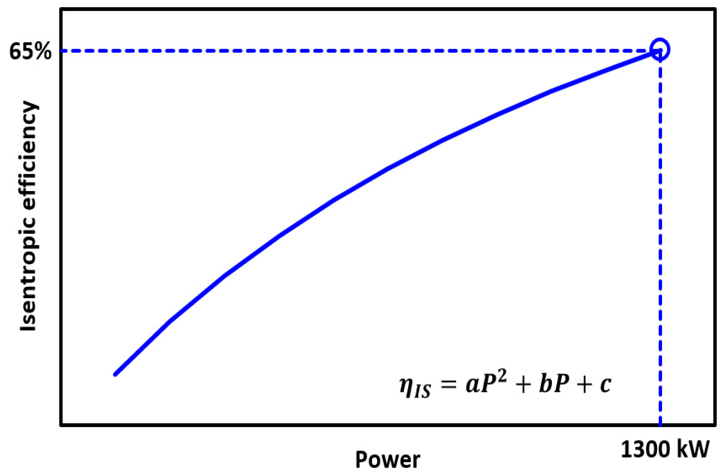
| first parameter of polynomial regression, Figure 19 (kW−2) | |
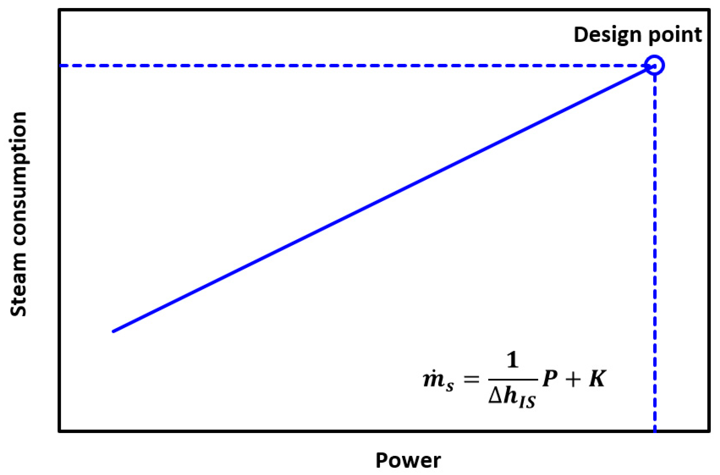
| parameter, Equation (2) (kW) | |
| second parameter of polynomial regression, Figure 19 (kW−1) | |
| parameter, Equation (2) | |
| third parameter of polynomial regression, Figure 19 | |
| diameter (m) | |
| shaft speed (rpm) | |
| gravitational acceleration, | |
| specific enthalpy (kJ·kg−1) | |
| intercept, Equation (1) (kW) | |
| slope, Equation (1) (kJ·kg−1) | |
| intercept, Equations (3), (13) and (14) (kg·s−1) | |
| length (m) | |
| mass flow rate (kg·s−1) | |
| power (kW) | |
| pressure, Equations (4)–(6) (Pa) | |
| length-specific heat flux (W·m−1) | |
| fluid mean transport velocity (m·s−1) | |
| net work (kW) | |
| geographical height (m) | |
| Greek symbols | |
| heat transfer coefficient (W·m−2·K−1) | |
| dimensionless parameter, Equation (4) | |
| difference | |
| specific mechanical energy (kJ·kg−1) | |
| efficiency | |
| overall heat transfer coefficient (W·m−1·K−1) | |
| friction factor | |
| coefficient of local dissipation | |
| density (kg·m−3) | |
| Subscripts | |
| A | ambient |
| d | design |
| dis | dissipation |
| F | fluid |
| I | insulation |
| IS | isentropic |
| max | maximal |
| mech | mechanical |
| W | wall |
Appendix A


References
- Murugan, S.; Horák, B. Tri and polygeneration systems—A review. Renew. Sustain. Energy Rev. 2016, 60, 1032–1051. [Google Scholar] [CrossRef]
- Jana, K.; Ray, A.; Majoumerd, M.M.; Assadi, M.; De, S. Polygeneration as a future sustainable energy solution—A comprehensive review. Appl. Energy 2017, 202, 88–111. [Google Scholar] [CrossRef]
- Baláž, V.; Nežinský, E.; Jeck, T.; Filčák, R. Energy and Emission Efficiency of the Slovak Regions. Sustainability 2020, 12, 2611. [Google Scholar] [CrossRef]
- Brożyna, J.; Strielkowski, W.; Fomina, A.; Nikitina, N. Renewable Energy and EU 2020 Target for Energy Efficiency in the Czech Republic and Slovakia. Energies 2020, 13, 965. [Google Scholar] [CrossRef]
- Rehfeldt, M.; Worrell, E.; Eichhammer, W.; Fleiter, T. A review of the emission reduction potential of fuel switch towards biomass and electricity in European basic materials industry until 2030. Renew. Sustain. Energy Rev. 2020, 120, 109672. [Google Scholar] [CrossRef]
- Korkmaz, P.; Gardumi, F.; Avgerinopoulos, G.; Blesl, M.; Fahl, U. A comparison of three transformation pathways towards a sustainable European society—An integrated analysis from an energy system perspective. Energy Strategy Rev. 2020, 28, 100461. [Google Scholar] [CrossRef]
- Martins, F.; Felgueiras, C.; Smitkova, M.; Caetano, N. Analysis of Fossil Fuel Energy Consumption and Environmental Impacts in European Countries. Energies 2019, 12, 964. [Google Scholar] [CrossRef]
- Malinauskaite, J.; Jouhara, H.; Ahmad, L.; Milani, M.; Montorsi, L.; Venturelli, M. Energy efficiency in industry: EU and national policies in Italy and the UK. Energy 2019, 172, 255–269. [Google Scholar] [CrossRef]
- Linares, P.; Pintos, P.; Würzburg, K. Assessing the potential and costs of reducing energy demand. Energy Transit. 2017, 1, 4. [Google Scholar] [CrossRef]
- Maciková, L.; Smorada, M.; Dorčák, P.; Beug, B.; Markovič, P. Financial Aspects of Sustainability: An Evidence from Slovak Companies. Sustainability 2018, 10, 2274. [Google Scholar] [CrossRef]
- Lieskovský, M.; Trenčiansky, M.; Majlingová, A.; Jankovský, J. Energy Resources, Load Coverage of the Electricity System and Environmental Consequences of the Energy Sources Operation in the Slovak Republic—An Overview. Energies 2019, 12, 1701. [Google Scholar] [CrossRef]
- Ghoniem, A.F. Needs, resources and climate change: Clean and efficient conversion technologies. Prog. Energy Combust. Sci. 2011, 37, 15–51. [Google Scholar] [CrossRef]
- Sutherland, B.R. Sustainably Heating Heavy Industry. Joule 2020, 4, 14–16. [Google Scholar] [CrossRef]
- Rivas, D.F.; Castro-Hernández, E.; Villanueva Perales, A.L.; van der Meer, W. Evaluation method for process intensification alternatives. Chem. Eng. Process.-Process Intensif. 2018, 123, 221–232. [Google Scholar] [CrossRef]
- Ifaei, P.; Safder, U.; Yoo, C. Multi-scale smart management of integrated energy systems, Part 1: Energy, economic, environmental, exergy, risk (4ER) and water-exergy nexus analyses. Energy Convers. Manag. 2019, 197, 111851. [Google Scholar] [CrossRef]
- Safder, U.; Ifaei, P.; Yoo, C. Multi-scale smart management of integrated energy systems, Part 2: Weighted multi-objective optimization, multi-criteria decision making, and multi-scale management (3M) methodology. Energy Convers. Manag. 2019, 198, 111830. [Google Scholar] [CrossRef]
- Rong, A.; Lahdelma, R. Role of polygeneration in sustainable energy system development challenges and opportunities from optimization viewpoints. Renew. Sustain. Energy Rev. 2016, 53, 363–372. [Google Scholar] [CrossRef]
- Pintarič, Z.N.; Varbanov, P.S.; Klemeš, J.J.; Kravanja, Z. Multi-objective multi-period synthesis of energy efficient processes under variable environmental taxes. Energy 2019, 189, 116182. [Google Scholar] [CrossRef]
- Al Moussawi, H.; Fardoun, F.; Louahlia, H. Selection based on differences between cogeneration and trigeneration in various prime mover technologies. Renew. Sustain. Energy Rev. 2017, 74, 491–511. [Google Scholar] [CrossRef]
- Bamufleh, H.S.; Ponce-Ortega, J.M.; El-Halwagi, M.M. Multi-objective optimization of process cogeneration systems with economic, environmental, and social tradeoffs. Clean Technol. Environ. Policy 2012, 15, 185–197. [Google Scholar] [CrossRef]
- Chen, Z.; Wang, J. Heat, mass, and work exchange networks. Front. Chem. Sci. Eng. 2012, 6, 484–502. [Google Scholar] [CrossRef]
- Chew, K.; Klemeš, J.; Alwi, S.; Manan, Z.; Reverberi, A. Total Site Heat Integration Considering Pressure Drops. Energies 2015, 8, 1114–1137. [Google Scholar] [CrossRef]
- Fan, Y.V.; Chin, H.H.; Klemeš, J.J.; Varbanov, P.S.; Liu, X. Optimisation and process design tools for cleaner production. J. Clean. Prod. 2020, 247, 119181. [Google Scholar] [CrossRef]
- Frate, G.F.; Ferrari, L.; Lensi, R.; Desideri, U. Steam expander as a throttling valve replacement in industrial plants: A techno-economic feasibility analysis. Appl. Energy 2019, 238, 11–21. [Google Scholar] [CrossRef]
- Ge, Z.; Zhang, F.; Sun, S.; He, J.; Du, X. Energy Analysis of Cascade Heating with High Back-Pressure Large-Scale Steam Turbine. Energies 2018, 11, 119. [Google Scholar] [CrossRef]
- Hanus, K.; Variny, M.; Illés, P. Assessment and Prediction of Complex Industrial Steam Network Operation by Combined Thermo-Hydrodynamic Modeling. Processes 2020, 8, 622. [Google Scholar] [CrossRef]
- Kler, A.M.; Stepanova, E.L.; Maksimov, A.S. Investigating the efficiency of a steam-turbine heating plant with a back-pressure steam turbine and waste-heat recovery. Thermophys. Aeromech. 2019, 25, 929–938. [Google Scholar] [CrossRef]
- Liew, P.Y.; Wan Alwi, S.R.; Varbanov, P.S.; Manan, Z.A.; Klemeš, J.J. Centralised utility system planning for a Total Site Heat Integration network. Comput. Chem. Eng. 2013, 57, 104–111. [Google Scholar] [CrossRef]
- Marton, S.; Svensson, E.; Subiaco, R.; Bengtsson, F.; Harvey, S. A Steam Utility Network Model for the Evaluation of Heat Integration Retrofits—A Case Study of an Oil Refinery. J. Sustain. Dev. Energy Water Environ. Syst. 2017, 5, 560–578. [Google Scholar] [CrossRef][Green Version]
- Mrzljak, V.; Poljak, I.; Mrakovčić, T. Energy and exergy analysis of the turbo-generators and steam turbine for the main feed water pump drive on LNG carrier. Energy Convers. Manag. 2017, 140, 307–323. [Google Scholar] [CrossRef]
- Ng, R.T.L.; Loo, J.S.W.; Ng, D.K.S.; Foo, D.C.Y.; Kim, J.-K.; Tan, R.R. Targeting for cogeneration potential and steam allocation for steam distribution network. Appl. Therm. Eng. 2017, 113, 1610–1621. [Google Scholar] [CrossRef]
- Sanaye, S.; Khakpaay, N.; Chitsaz, A. Thermo-economic and environmental multi-objective optimization of a novel arranged biomass-fueled gas engine and backpressure steam turbine combined system for pulp and paper mills. Sustain. Energy Technol. Assess. 2020, 40, 100778. [Google Scholar] [CrossRef]
- Sun, L.; Doyle, S.; Smith, R. Heat recovery and power targeting in utility systems. Energy 2015, 84, 196–206. [Google Scholar] [CrossRef]
- Sun, W.; Zhao, Y.; Wang, Y. Electro- or Turbo-Driven?—Analysis of Different Blast Processes of Blast Furnace. Processes 2016, 4, 28. [Google Scholar] [CrossRef]
- Tian, Y.; Xing, Z.; He, Z.; Wu, H. Modeling and performance analysis of twin-screw steam expander under fluctuating operating conditions in steam pipeline pressure energy recovery applications. Energy 2017, 141, 692–701. [Google Scholar] [CrossRef]
- Wu, L.; Liu, Y.; Liang, X.; Kang, L. Multi-objective optimization for design of a steam system with drivers option in process industries. J. Clean. Prod. 2016, 136, 89–98. [Google Scholar] [CrossRef]
- Wu, Y.; Wang, R.; Wang, Y.; Feng, X. An area-wide layout design method considering piecewise steam piping and energy loss. Chem. Eng. Res. Des. 2018, 138, 405–417. [Google Scholar] [CrossRef]
- Zhao, L.; Zhong, W.; Du, W. Data-Driven Robust Optimization for Steam Systems in Ethylene Plants under Uncertainty. Processes 2019, 7, 744. [Google Scholar] [CrossRef]
- Huang, Y.; Hou, W.; Huang, Y.; Li, J.; Li, Q.; Wang, D.; Zhang, Y. Multi-Objective Optimal Operation for Steam Power Scheduling Based on Economic and Exergetic Analysis. Energies 2020, 13, 1886. [Google Scholar] [CrossRef]
- Marton, S.; Svensson, E.; Harvey, S. Operability and Technical Implementation Issues Related to Heat Integration Measures—Interview Study at an Oil Refinery in Sweden. Energies 2020, 13, 3478. [Google Scholar] [CrossRef]
- Beangstrom, S.G.; Majozi, T. Steam system network synthesis with hot liquid reuse: II. Incorporating shaft work and optimum steam levels. Comput. Chem. Eng. 2016, 85, 202–209. [Google Scholar] [CrossRef]
- Min, K.-J.; Binns, M.; Oh, S.-Y.; Cha, H.-Y.; Kim, J.-K.; Yeo, Y.-K. Screening of site-wide retrofit options for the minimization of CO2 emissions in process industries. Appl. Therm. Eng 2015, 90, 335–344. [Google Scholar] [CrossRef]
- Bütün, H.; Kantor, I.; Maréchal, F. Incorporating Location Aspects in Process Integration Methodology. Energies 2019, 12, 3338. [Google Scholar] [CrossRef]
- Wu, Y.; Wang, Y.; Feng, X. A heuristic approach for petrochemical plant layout considering steam pipeline length. Chin. J. Chem. Eng. 2016, 24, 1032–1037. [Google Scholar] [CrossRef]
- Svensson, E.; Morandin, M.; Harvey, S.; Papadokonstantakis, S. Studying the Role of System Aggregation in Energy Targeting: A Case Study of a Swedish Oil Refinery. Energies 2020, 13, 958. [Google Scholar] [CrossRef]
- Chowdhury, J.I.; Hu, Y.; Haltas, I.; Balta-Ozkan, N.; Matthew, G., Jr.; Varga, L. Reducing industrial energy demand in the UK: A review of energy efficiency technologies and energy saving potential in selected sectors. Renew. Sustain. Energy Rev. 2018, 94, 1153–1178. [Google Scholar] [CrossRef]
- Variny, M.; Blahušiak, M.; Mierka, O.; Godó, Š.; Margetíny, T. Energy saving measures from their cradle to full adoption with verified, monitored, and targeted performance: A look back at energy audit at Catalytic Naphtha Reforming Unit (CCR). Energy Effic. 2019, 12, 1771–1793. [Google Scholar] [CrossRef]
- Variny, M.; Furda, P.; Švistun, L.; Rimár, M.; Kizek, J.; Kováč, N.; Illés, P.; Janošovský, J.; Váhovský, J.; Mierka, O. Novel Concept of Cogeneration-Integrated Heat Pump-Assisted Fractionation of Alkylation Reactor Effluent for Increased Power Production and Overall CO2 Emissions Decrease. Processes 2020, 8, 183. [Google Scholar] [CrossRef]
- van de Bor, D.M.; Infante Ferreira, C.A.; Kiss, A.A. Low grade waste heat recovery using heat pumps and power cycles. Energy 2015, 89, 864–873. [Google Scholar] [CrossRef]
- Gangar, N.; Macchietto, S.; Markides, C.N. Recovery and Utilization of Low-Grade Waste Heat in the Oil-Refining Industry Using Heat Engines and Heat Pumps: An International Technoeconomic Comparison. Energies 2020, 13, 2560. [Google Scholar] [CrossRef]
- Kazemi, A.; Hosseini, M.; Mehrabani-Zeinabad, A.; Faizi, V. Evaluation of different vapor recompression distillation configurations based on energy requirements and associated costs. Appl. Therm. Eng. 2016, 94, 305–313. [Google Scholar] [CrossRef]
- Holmberg, H.; Ruohonen, P.; Ahtila, P. Determination of the Real Loss of Power for a Condensing and a Backpressure Turbine by Means of Second Law Analysis. Entropy 2009, 11, 702–712. [Google Scholar] [CrossRef]
- Fontalvo, J. Using user models in Matlab® within the Aspen Plus® interface with an Excel® link. Ing. Investig. 2014, 34, 39–43. [Google Scholar] [CrossRef]
- Fontalvo, J.; Cuellar, P.; Timmer, J.M.K.; Vorstman, M.A.G.; Wijers, J.G.; Keurentjes, J.T.F. Comparing Pervaporation and Vapor Permeation Hybrid Distillation Processes. Ind. Eng. Chem. Res. 2005, 44, 5259–5266. [Google Scholar] [CrossRef]
- Darkwah, K.; Knutson, B.L.; Seay, J.R. Multi-objective versus single-objective optimization of batch bioethanol production based on a time-dependent fermentation model. Clean Technol. Environ. Policy 2018, 20, 1271–1285. [Google Scholar] [CrossRef]
- Briones Ramírez, A.; Gutiérrez Antonio, C. Multiobjective Optimization of Chemical Processes with Complete Models using MATLAB and Aspen Plus. Comput. Sist. 2018, 22, 1157–1170. [Google Scholar] [CrossRef]
- Muñoz, C.A.; Telen, D.; Nimmegeers, P.; Cabianca, L.; Logist, F.; Van Impe, J. Investigating practical aspects of the exergy based multi-objective optimization of chemical processes. Comput. Aided Chem. Eng. 2017, 40, 2173–2178. [Google Scholar] [CrossRef]
- Cui, C.; Zhang, X.; Sun, J. Design and optimization of energy-efficient liquid-only side-stream distillation configurations using a stochastic algorithm. Chem. Eng. Res. Des. 2019, 145, 48–52. [Google Scholar] [CrossRef]
- Capra, F.; Magli, F.; Gatti, M. Biomethane liquefaction: A systematic comparative analysis of refrigeration technologies. Appl. Therm. Eng. 2019, 158, 113815. [Google Scholar] [CrossRef]
- dos Santos Vidal, S.F.; Schmitz, J.E.; Franco, I.C.; Frattini Fileti, A.M.; Da Silva, F.V. Fuzzy Multivariable Control Strategy Applied to a Refrigeration System. Chem. Prod. Process Modeling 2017, 12, 20160033. [Google Scholar] [CrossRef]
- Ryu, H.; Lee, J.M. Model Predictive Control (MPC)-Based Supervisory Control and Design of Off-Gas Recovery Plant with Periodic Disturbances from Parallel Batch Reactors. Ind. Eng. Chem. Res. 2016, 55, 3013–3025. [Google Scholar] [CrossRef]
- Silva, W.C.; Araújo, E.C.C.; Calmanovici, C.E.; Bernardo, A.; Giulietti, M. Environmental assessment of a standard distillery using aspen plus®: Simulation and renewability analysis. J. Clean. Prod. 2017, 162, 1442–1454. [Google Scholar] [CrossRef]
- Ping, W.; Changfang, X.; Shiming, X.; Yulin, G. Study of Direct Compression Heat Pump Energy-saving Technology. Procedia Environ. Sci. 2012, 12, 394–399. [Google Scholar] [CrossRef][Green Version]
- Gao, X.; Gu, Q.; Ma, J.; Zeng, Y. MVR heat pump distillation coupled with ORC process for separating a benzene-toluene mixture. Energy 2018, 143, 658–665. [Google Scholar] [CrossRef]
- Peng, D.-Y.; Robinson, D.B. A New Two-Constant Equation of State. Ind. Eng. Chem. Fundam. 1976, 15, 59–64. [Google Scholar] [CrossRef]
- Ho, Q.N.; Yoo, K.S.; Lee, B.G.; Lim, J.S. Measurement of vapor–liquid equilibria for the binary mixture of propylene (R-1270)+propane (R-290). Fluid Phase Equilibria 2006, 245, 63–70. [Google Scholar] [CrossRef]
- Sarath Yadav, E.; Indiran, T.; Nayak, D.; Aditya Kumar, C.; Selvakumar, M. Simulation study of distillation column using Aspen plus. Mater. Today Proc. 2020. in Press. [Google Scholar] [CrossRef]
- Querol, E.; Gonzalez-Regueral, B.; Ramos, A.; Perez-Benedito, J.L. Novel application for exergy and thermoeconomic analysis of processes simulated with Aspen Plus®. Energy 2011, 36, 964–974. [Google Scholar] [CrossRef]
- Lan, W.; Chen, G.; Zhu, X.; Wang, X.; Liu, C.; Xu, B. Biomass gasification-gas turbine combustion for power generation system model based on ASPEN PLUS. Sci. Total Environ. 2018, 628–629, 1278–1286. [Google Scholar] [CrossRef]
- Li, S.; Li, F. Prediction of Cracking Gas Compressor Performance and Its Application in Process Optimization. Chin. J. Chem. Eng. 2012, 20, 1089–1093. [Google Scholar] [CrossRef]
- Liu, Z.; Karimi, I.A. Simulating combined cycle gas turbine power plants in Aspen HYSYS. Energy Convers. Manag. 2018, 171, 1213–1225. [Google Scholar] [CrossRef]
- Pouransari, N.; Bocquenet, G.; Maréchal, F. Site-scale process integration and utility optimization with multi-level energy requirement definition. Energy Convers. Manag. 2014, 85, 774–783. [Google Scholar] [CrossRef]
- Zhu, Q.; Luo, X.; Zhang, B.; Chen, Y.; Mo, S. Mathematical modeling, validation, and operation optimization of an industrial complex steam turbine network-methodology and application. Energy 2016, 97, 191–213. [Google Scholar] [CrossRef]
- Sun, L.; Doyle, S.; Smith, R. Understanding steam costs for energy conservation projects. Appl. Energy 2016, 161, 647–655. [Google Scholar] [CrossRef]
- Golmohamadi, G.; Asadi, A. Integration of joint power-heat flexibility of oil refinery industries to uncertain energy markets. Energies 2020, 13, 4874. [Google Scholar] [CrossRef]
- Abril, A.F. Aspen Plus—Matlab Link. Available online: https://www.mathworks.com/matlabcentral/fileexchange/69464-aspen-plus-matlab-link (accessed on 9 September 2020).
- Lu, J.; Tang, J.; Chen, X.; Cui, M.; Fei, Z.; Zhang, Z.; Qiao, X. Global Optimization of Reactive Distillation Processes using Bat Algorithm. Chem. Eng. Trans. 2017, 61, 1279–1284. [Google Scholar] [CrossRef]
- Gulied, M.; Al Nouss, A.; Khraisheh, M.; AlMomani, F. Modeling and simulation of fertilizer drawn forward osmosis process using Aspen Plus-MATLAB model. Sci. Total Environ. 2020, 700, 134461. [Google Scholar] [CrossRef]
- Aspen Technology Inc. Aspen Plus User Guide; Version 10.2; Aspen Technology Inc.: Cambridge, MA, USA, 2000. [Google Scholar]
- Mavromatis, S.P.; Kokossis, A.C. Conceptual optimisation of utility networks for operational variations—I. Targets and level optimisation. Chem. Eng. Sci. 1998, 53, 1585–1608. [Google Scholar] [CrossRef]
- Varbanov, P.S.; Doyle, S.; Smith, R. Modelling and Optimization of Utility Systems. Chem. Eng. Res. Des. 2004, 82, 561–578. [Google Scholar] [CrossRef]
- Mavromatis, S.P.; Kokossis, A.C. Conceptual optimisation of utility networks for operational variations—II. Network development and optimisation. Chem. Eng. Sci. 1998, 53, 1609–1630. [Google Scholar] [CrossRef]
- Brkić, D.; Praks, P. Unified Friction Formulation from Laminar to Fully Rough Turbulent Flow. Appl. Sci. 2018, 8, 2036. [Google Scholar] [CrossRef]
- Wang, H.; Wang, H.; Zhu, T.; Deng, W. A novel model for steam transportation considering drainage loss in pipeline networks. Appl. Energy 2017, 188, 178–189. [Google Scholar] [CrossRef]


| Parameter/Feature | Method | ||||||||
|---|---|---|---|---|---|---|---|---|---|
| Wu et al. [36] | Ng et al. [31] | Frate et al. [24] | Marton et al. 2017 [29] | Sun et al. 2016 [34] | Bütün et al. [43] | Mrzljak et al. [30] | Tian et al. [35] | Proposed Method | |
| Inlet steam temperature & pressure | Fixed | Fixed | SS; SA | NP | SA | Fixed | Varying; process data | SS; SA | Varying; process data |
| Discharge steam pressure | Fixed | Fixed | SA | NP | NP | Fixed | Varying; process data | SA | Varying; process data |
| Discharge steam temperature | Fixed | Fixed | WS | NP | NP | Fixed | WS | WS | Calc.; polytropic expansion |
| Frictional pressure losses | 🗶 | 🗶 | 🗶 | 🗶 | 🗶 | 🗸 | 🗶 | 🗸 | 🗸 |
| Heat losses from pipelines | 🗶 | 🗶 | 🗶 | 🗶 | 🗶 | 🗸 | 🗶 | 🗶 | 🗸 |
| Turbine revolutions | 🗶 | 🗶 | 🗶 | 🗶 | Varying; NP | 🗶 | Varying | SA | Varying; process data |
| Turbine efficiency | Reg. | Fixed | SA | NP | Varying | NP | Calc. | Calc. | Calc. |
| Driven equipment efficiency | Fixed | N/A | N/A | N/A | Varying; NP | N/A | Efficiency map | N/A | Efficiency map |
| Shaft work required | Fixed | N/A | N/A | N/A | Calc.; process-dependent | N/A | Varying; process data | N/A | Calc.; process-dependent |
| Process modeled | 🗶 | N/A | N/A | Aspen utilities planner + Excel | Process and steam BE | Steam and heat BE | 🗶 | N/A | Aspen Plus® linked with MATLAB® |
| Equipment/Material Stream/Unit | Data | Purpose | Details |
|---|---|---|---|
| Propylene (product stream) | Total mass flow | Simulation | Together with propane stream represents the feed stream |
| Propylene content | |||
| Propane (component analysis) | Simulation | Feed stream composition | |
| Column | Head pressure | Simulation | |
| Bottoms pressure | Simulation | ||
| Suction drum | Pressure | Simulation | |
| Compressor | Exhaust pressure | Simulation | |
| Exhaust temperature | Verification | Compressor exhaust temperature documents isentropic efficiency calculation accuracy | |
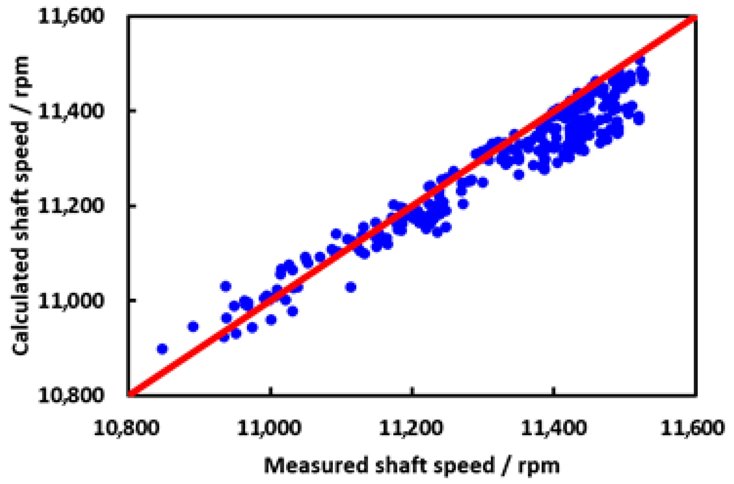
| Shaft speed | Verification | Shaft speed documents compressor performance calculation accuracy | |
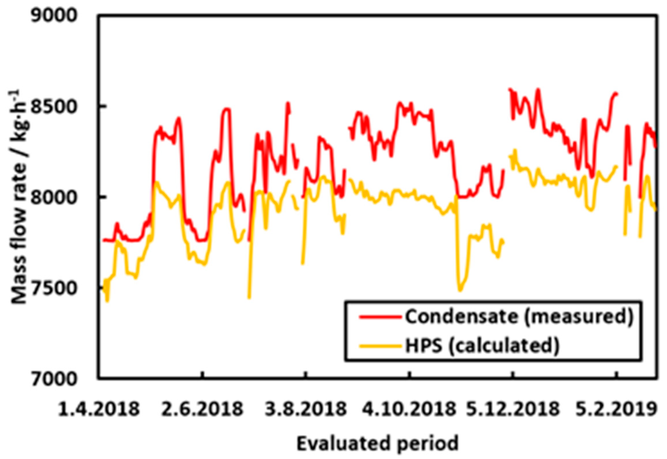
| Turbine | Steam consumption/condensate mass flow | Verification | For systems where steam consumption is not measured directly, it is possible to measure mass flow of turbine condensate |
| Condensate pump by-pass valve position | Verification | When measuring condensate mass flow, it is sensible to check whether condensate pump by-pass is in operation and to what degree | |
| Live steam temperature | Simulation | ||
| Exhaust pressure/condenser temperature | Simulation | For systems where exhaust pressure is not measured directly, it is possible to estimate it based on the condenser temperature | |
| HPS from BL | Mass flow | Simulation | |
| (utility stream) | Temperature | Simulation | |
| Pressure | Simulation | ||
| MPS from BL | Mass flow | Simulation | |
| (utility stream) | Temperature | Simulation | |
| Pressure | Simulation | ||
| CHP unit | HPS mass flow | Simulation | |
| MPS mass flow | Simulation |
| Approach | Pipe Length | Pipeline Heat Loss | Pressure Drop | Steam Quality Fluctuations | Varying Shaft Speed | Varying Isentropic Efficiency | |
|---|---|---|---|---|---|---|---|
| Real Insulation Conductivity | Design Insulation Conductivity | ||||||
| Case 1 | 100% | 🗸 | 🗶 | 🗸 | 🗸 | 🗸 | 🗸 |
| Case 2 | 100% | 🗶 | 🗸 | 🗸 | 🗸 | 🗸 | 🗸 |
| Case 3 | 100% | 🗶 | 🗶 | 🗸 | 🗸 | 🗸 | 🗸 |
| Case 4 | - | 🗶 | 🗶 | 🗶 | 🗸 | 🗸 | 🗸 |
| Case 5 | - | 🗶 | 🗶 | 🗶 | 🗶 | 🗸 | 🗸 |
| Case 6 | - | 🗶 | 🗶 | 🗶 | 🗶 | 🗶 | 🗸 |
| Case 7 | 1000% | 🗸 | 🗶 | 🗸 | 🗸 | 🗸 | 🗸 |
| Case 8 | 1000% | 🗶 | 🗸 | 🗸 | 🗸 | 🗸 | 🗸 |
| Case 9 | 1000% | 🗶 | 🗶 | 🗸 | 🗸 | 🗸 | 🗸 |
| Case 10 | - | 🗶 | 🗶 | 🗶 | 🗶 | 🗶 | 🗶 |
| Ambient Temperature/°C | Nominal HPS Consumption/kg·h−1 | Nominal Δh/kJ·kg−1 | ΔhIS/kJ·kg−1 | K/kg·s−1 | a·107 | b·104 | c·102 | |
|---|---|---|---|---|---|---|---|---|
| Case 1 | 10 | 34,703 | 158.6 | 244.0 | 4.312 | −2.101 | 7.169 | 6.953 |
| 35 | 34,703 | 158.6 | 244.0 | 4.312 | −2.101 | 7.169 | 6.953 | |
| −14 | 34,724 | 158.5 | 243.8 | 4.314 | −2.101 | 7.170 | 6.954 | |
| Case 2 | 10 | 34,685 | 158.8 | 244.3 | 4.314 | −2.098 | 7.164 | 6.933 |
| 35 | 34,682 | 158.8 | 244.3 | 4.313 | −2.099 | 7.164 | 6.935 | |
| −14 | 34,688 | 158.8 | 244.3 | 4.314 | −2.098 | 7.163 | 6.930 | |
| Case 3 | N/A | 34,623 | 159.0 | 244.6 | 4.303 | −2.100 | 7.168 | 6.947 |
| Cases 4–6 | N/A | 33,954 | 162.1 | 249.4 | 4.219 | −2.101 | 7.169 | 6.953 |
| Case 7 | 10 | 42,782 | 128.7 | 198.0 | 5.318 | −2.100 | 7.166 | 6.942 |
| 35 | 42,707 | 128.9 | 198.3 | 5.308 | −2.100 | 7.168 | 6.948 | |
| −14 | 42,855 | 128.5 | 197.7 | 5.328 | −2.103 | 7.178 | 6.953 | |
| Case 8 | 10 | 42,172 | 130.5 | 200.8 | 5.239 | −2.101 | 7.170 | 6.955 |
| 35 | 42,137 | 130.7 | 201.1 | 5.240 | −2.098 | 7.159 | 6.945 | |
| −14 | 42,208 | 130.4 | 200.6 | 5.244 | −2.103 | 7.176 | 6.961 | |
| Case 9 | N/A | 41,182 | 133.7 | 205.7 | 5.119 | −2.100 | 7.166 | 6.942 |
| Base Case | Average Relative Deviation in HPS Consumption/% | |||||||
|---|---|---|---|---|---|---|---|---|
| Case 2 | Case 3 | Case 4 | Case 5 | Case 6 | Case 8 | Case 9 | Case 10 | |
| Case 1 | 0.08 | 0.31 | 2.21 | 2.32 | 2.84 | - | - | 5.01 |
| Case 7 | - | - | 20.35 | 20.09 | 20.52 | 1.61 | 3.74 | 22.28 |
Publisher’s Note: MDPI stays neutral with regard to jurisdictional claims in published maps and institutional affiliations. |
© 2020 by the authors. Licensee MDPI, Basel, Switzerland. This article is an open access article distributed under the terms and conditions of the Creative Commons Attribution (CC BY) license (http://creativecommons.org/licenses/by/4.0/).
Share and Cite
Furda, P.; Variny, M.; Labovská, Z.; Cibulka, T. Process Drive Sizing Methodology and Multi-Level Modeling Linking MATLAB® and Aspen Plus® Environment. Processes 2020, 8, 1495. https://doi.org/10.3390/pr8111495
Furda P, Variny M, Labovská Z, Cibulka T. Process Drive Sizing Methodology and Multi-Level Modeling Linking MATLAB® and Aspen Plus® Environment. Processes. 2020; 8(11):1495. https://doi.org/10.3390/pr8111495
Chicago/Turabian StyleFurda, Patrik, Miroslav Variny, Zuzana Labovská, and Tomáš Cibulka. 2020. "Process Drive Sizing Methodology and Multi-Level Modeling Linking MATLAB® and Aspen Plus® Environment" Processes 8, no. 11: 1495. https://doi.org/10.3390/pr8111495
APA StyleFurda, P., Variny, M., Labovská, Z., & Cibulka, T. (2020). Process Drive Sizing Methodology and Multi-Level Modeling Linking MATLAB® and Aspen Plus® Environment. Processes, 8(11), 1495. https://doi.org/10.3390/pr8111495