Article

Laser-Induced Ignition and Combustion Behavior of Individual Graphite Microparticles in a Micro-Combustor

1
Institute of Energy, Department of Physics, Hangzhou Dianzi University, Hangzhou 310018, China
2
College of Materials and Environmental Engineering, Hangzhou Dianzi University, Hangzhou 310018, China
*
Authors to whom correspondence should be addressed.
Processes 2020, 8(11), 1493; https://doi.org/10.3390/pr8111493
Submission received: 24 October 2020 / Revised: 13 November 2020 / Accepted: 16 November 2020 / Published: 19 November 2020
(This article belongs to the Special Issue Experimental and Computational Combustion Process)

Abstract

:
Microscale combustion has potential application in a micro power generator. This paper studied the ignition and combustion behavior of individual graphite microparticles in a micro-combustor to explore the utilization of carbon-based fuels at the microscale system. The individual graphite microparticles inside the micro-combustor were ignited by a highly focused laser in an air flow with natural convection at atmospheric temperature and pressure. The results show that the ignition of graphite microparticles was heterogeneous. The particle diameter had a small weak effect on ignition delay time and threshold ignition energy. The micro-combustor wall heat losses had significant effects on the ignition and combustion. During combustion, flame instability, photophoresis, repetitive extinction and reignition were identified. The flame structure was asymmetric, and the fluctuation of flame front and radiation intensity showed combustion instability. Photophoretic force pushed the graphite away from the focal point and resulted in extinction. Owing to large wall heat loss, the flame quickly extinguished. However, the graphite was inductively reignited by laser.

1. Introduction

Combustion of solid carbon-based fuels is an important research subject, and is indispensable for practical utilization of coal [1], biomass [2], solid waste [3], etc. Owing to complexities involved and appearances of new technology concepts for combustion, further studies of pure carbon (like char and graphite) combustion play a significant role in revealing the burning mechanism of carbon-based fuels [4]. Valerio et al. [5] experimentally investigated the burnout time and the ignition temperature of individual char particles, and finally presented a predictive model of burnout time. Heating, oxidation [6,7], ignition [8], and burning [9,10] characteristics of graphite have been extensively studied, not only experimentally, but also theoretically and/or numerically. Qu et al. [8] reported that the graphite particles were heated gradually, and accumulated heat released the oxidation reaction that triggered the ignition of graphite. Significant differences among the burning behaviors of graphite exist under different operation conditions. Makino et al. [9,11,12,13] studied the burning characteristics of graphite in detail, including flame structure and combustion rate of graphite in a stagnation air or water vapor flow under high temperature.
These previous investigations have demonstrated general characteristics of heating, oxidation, ignition and burning behavior of graphite at the macroscale. Nevertheless, at the microscale, no studies have been done to understand the ignition and/or combustion behavior of graphite.
Generally, at the microscale, gas phase hydrogen or hydrocarbon fuels are widely used, and the ignition and combustion mechanisms have been theoretically and experimentally investigated. As the scale of the combustion chamber decreases from macro to micro, igniting the gas phase hydrogen or hydrocarbon fuels and establishing sustainable combustion become more challenging due to the increase of heat loss and radical loss on the combustor wall [14]. Some events that may take place either individually or jointly during combustion have not been understood because of the complexity of physical and chemical interactions [15].
To better understand the ignition and burning behavior of solid fuels like graphite in a limited micro-combustor, we attempted to design and integrate a microscale combustion chamber, laser ignition, in situ microimaging and flame radiation measurement. The experiments were conducted to observe the ignition and burning behavior of individual micron-sized graphite particles, and to understand the complex phenomena involved during the early heating, ignition and burnout stages. In a micro-combustor, the use of laser radiation is most suitable for studying the ignition of solid fuels: (1) distortions of intrusive sources can be eliminated by positioning the ignition source distance from the ignition point; (2) the system complexity can be simplified by integrating with the microimaging system; and (3) it is able to direct specific mode or configuration energy for ignition, since laser power can be highly focused to a point, sheet or core.
The aims of the present study are: (1) to study the laser-induced ignition and combustion behavior of individual micron-sized graphite particles in a micro-combustor, and explore the effect of wall heat loss on the ignition and combustion; and (2) to demonstrate the flame structure, diffusion, radiation characteristics and burning stages, and identify the combustion phenomena including instability, repetitive extinction, reignition, etc.

2. Materials and Methods

2.1. Preparation and Characterization

The graphite powders (CAS: 7782-42-5) were purchased from Aladdin Industrial Corporation, Shanghai, China. The graphite microparticles appear black to the eye, and their purity reaches ~99.95% (metals basis) through high temperature purification. The melting point of graphite is ~3774 K, and its density is ~2.2 × 10³ kg/m3. The specific heat is ~710 J/(kg·K), and the thermal conductivity is ~129 W/(m·K). Graphite powders were characterized by scanning electron microscopy (SEM, Quanta 600FEG, FEI Company, Hillsboro, OR, USA) and the morphology is shown in Figure 1. It can be obviously seen that the graphite has a layered, planar structure. In each layer, the carbon atoms are arranged in a honeycomb lattice with separation of 0.142 nm, and the distance between planes is 0.335 nm [16].
Energy dispersive spectrometer analysis (EDS, INCA Energy 300, Oxford instruments, Abingdon, UK) of graphite powders (Figure 2) demonstrated that the atom percentage of carbon and oxygen were 89.16% and 10.84% respectively, indicating that the oxidation occurred on the surface of graphite powders.
The X-ray diffraction (XRD) pattern of graphite powders was obtained with a Bruke X’PERT diffractometer (Cu Ka radiation, 16 KW, D8 ADVANCE, Bruker AXS GmbH, Karlsruhe, Germany), as shown in Figure 3. The XRD pattern indicated that the graphite crystal has X-diffraction angle (2 theta) of 26.47 and 54.61, corresponding to the 002 and 004 crystallographic planes.

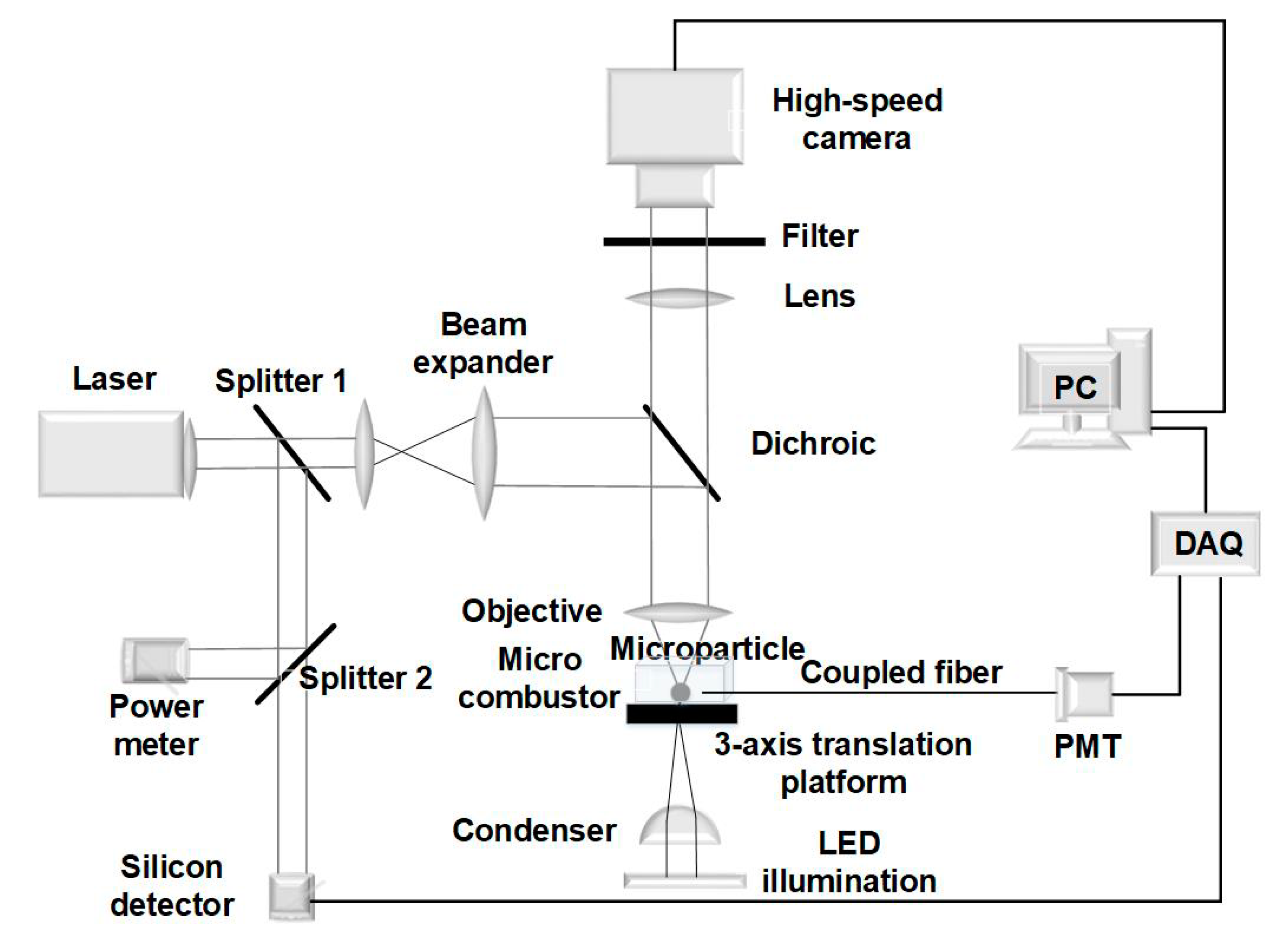
2.2. Experimental Setup for Ignition and Combustion Test

The experimental setup is shown in Figure 4. One dominant beam was used to ignite the graphite microparticles through splitter 1, beam expander, dichroic and the objective. The other beam was again split into two beams by splitter 2, and then reached the power meter and the silicon detector to evaluate the ignition power and the response time of the laser, respectively.
The ignition system and the illumination and microimaging system are similar to that described in our previous works [17,18,19]. The flame radiation detection system is composed of a lensed multimode fiber (MMF) and a photomultiplier tube (PMT H10722-20, Hamamatsu Corp., Hamamatsu, Japan). At one end of MMF, a lens was fabricated by high voltage fusion to enhance collection efficiency for the flame radiation signal. The lensed MMF was then placed into combustor; thus, the flame radiation signals could be picked up and delivered into PMT. The signals collected from both the silicon detector and the PMT were acquired by a data acquisition system (DAQ) (PCI-6221, National Instruments, Austin, TX, USA) and post processed using LabVIEW software.
The microscale combustion system includes the micro-combustor, pipes, adapting pieces and other accessories. The micro-combustor was fabricated by photo etching technology, which is made up of transparent cover glass (at the top) and flat glass (at the bottom). The inner dimensions are ~350 μm (width) × 100 μm (depth) × 20 mm (length), like a channel. With a 3-axis (X, Y, and Z) translation that manually adjusted with the resolution of 10 μm, the micro-combustor was fixed on the stage. The micron-sized graphite powders were placed into the micro-combustor by a pneumatic conveyor. The graphite microparticles were scattered in the micro-combustor. All accessories connecting with the micro-combustor were then removed. The micro-combustor was exposed in the surrounding atmosphere, and the air inside the micro-combustor diffused by natural convection.
The dimensions of the particle and flame profile were measured by comparing the scale at the same imaging condition and microscopic magnification with the calibration scale. All the photos and videos of ignition and burning behavior of graphite particles were acquired by CCD camera at 158 fps, and then post processed by self-programming digital image processing.
In general, the graphite microparticles are irregular and non-spherical. We define a characteristic dimension D (also called as equivalent diameter) to represent the graphite size. Statistical analysis shows that the size of graphite particles ranges from 1.0 μm to 15.0 μm.

3. Results and Discussion

3.1. Ignition

3.1.1. Ignition Mode

Essenhigh et al. [20] reported three ignition modes, including homogeneous, heterogeneous and combination modes, which depend on the heating rate and particle diameter. For this case, the graphite diameter is micron-sized, and the heating rate can be simply calculated by the conservation of energy. In the micro-combustor, the temperature evolution of the graphite particle (TP) absorbed laser radiation energy can be given by:
m P C P d T P d t = α Q ˙ L + Q ˙ R + Q ˙ c o n v + Q ˙ r a d
where Q ˙ L represents the laser power, and α is the absorption coefficient, which is ~0.8 at a laser wavelength of 1064 nm. Q ˙ R represents the heat of reaction. Q ˙ c o n v and Q ˙ r a d represent convective heat loss and radiative heat loss, respectively, which can be expressed:
Q ˙ c o n v = π D P μ g C g Pr g ( T g T p ) N u P
Q ˙ r a d = ε σ ( T g 4 T p 4 ) A P
In Equation (2), the Nusselt number ( N u P ) is a function of the Reynolds number ( Re P ):
N u P = 2 [ 1 + Re P 1 2 Pr g 1 3 / 3 ]
Re P = D P ρ g | u P u g | / μ g
where C, D, T, t, μ, ε, m, ρ, and σ represent the specific heat, diameter, temperature, time, dynamic viscosity, emissivity, mass, density, and Stefan-Boltzmann constant, respectively. Prg is the Prandtl number, and AP is the surface area of the particle. The subscripts p and g represent the graphite particle and ambient gas.
The graphite reacts with oxygen in air at nearly 900 K. Thus, as the temperature is below 900 K, the heat of reaction ( Q ˙ R ) can be ignored compared with the heating laser power. Figure 5 shows the temperature rising rate (heating rate) and convective and radiative losses.
The diameter of the focusing laser beam was ~3 μm, which was less than the size of a graphite particle. This means that the graphite particle was heated locally. For the graphite particles of 3 μm and 5 μm, the heating rate was above 108 K/s if 12.0 mW laser power was exerted. The surface temperature reached 900 K when a 3 μm particle was heated for 1.12 μs, and the convective and radiative heat losses were ~2.98 × 10⁻⁴ W and 8.77 × 10⁻⁶ W at that moment. It took 5.28 μs to arrive at 900 K for a particle of 5 μm, and the convective and radiative heat losses were about 5.00 × 10⁻⁴ W and 2.45 × 10⁻⁶ W. For the graphite particles of 7~11 μm, it took tens of hundreds of microseconds to get to 900 K at the graphite surface. The heating time to reach 900 K for 7 μm was almost half of the full width at half maximum (FWHM) of the first pulse (64.5 μs for 7.14 μm) shown in Figure 7. The convective and radiative heat losses were of the order of magnitude of 10−4 W and 10−6 W.
Since the heating rate was above 107 K/s, the ignition mode of the micron-sized graphite particle should be heterogeneous (Figure 6). The experimental result testified the heterogeneous mode, as shown in an example like Figure 6b. It can be observed that a local weak flame was above the particle.
Since the oxidation rate was extremely low, the heat of reaction is two or three orders of magnitude lower than the heating energy. This indicates that the laser energy dominantly contributes to heat the graphite particle and compensate for the convective and radiative heat losses. It is informative to note that the released heat of the exothermic reaction of graphite with oxygen was lower than the convective and radiative losses. This suggests that an individual graphite particle cannot self-sustainably combust due to the large heat loss towards the surrounding air.

3.1.2. Ignition Delay Time and Threshold Energy

Ignition of a graphite particle is governed by the ability to absorb a critical amount of energy from laser radiation. The graphite particle was firstly heated by the highly focused laser. As the requirement of activation energy of 188 ± 2.2 kJ/mol was met, the active sites at the surface of graphite reacted with oxygen [21]. The reaction of graphite with oxygen could be chemically or diffusively controlled, or a combination of the two, which depends on the surface temperature. At lower surface temperatures, a chemically controlled reaction occurs, and at the graphite surface, oxygen is excessive. The reaction rate depends only on the chemical kinetics of graphite and oxygen. Gulbransen et al. [22] showed that below 800 °C a small amount of surface oxide was formed. Whereas, at higher surface temperatures, at the surface, the oxygen is rapidly depleted, and the reaction rate will be limited by the oxygen diffusion rate to the reacting surface. At the surface of graphite, carbon underwent the reactions 2C + O2 → 2CO and C + CO2 → 2CO, while in the gas phase, the CO + 1/2O2 → CO2 reaction proceeded. As the surface temperature quickly surpasses 1000 K, the surface C + O2 → CO2 reaction can be excluded [23]. For this case, the air naturally diffuses on the surface of graphite. The chemically controlled reaction dominates the oxidation process at the initial heating stage.
Figure 7 shows a radiation signal of an individual graphite microparticle with the diameter of 7.25 μm in the micro-combustor. On the curve of the radiation signal, the first sharp pulse can be easily observed. This pulse has a narrow FWHM of ~128.6 μs, indicating that the graphite particle was quickly heated and then ignited. The ignition delay time (τ) of individual micron-sized graphite particles can be calculated by using the equation in our previous paper [18]. The ignition delay of the graphite particle was 0.15 ± 0.02 ms. The igniting power was ~12.0 mW, and thus the threshold ignition energy is calculated by multiplying the laser power and the delay time, which is about 1.80 ± 0.02 μJ.

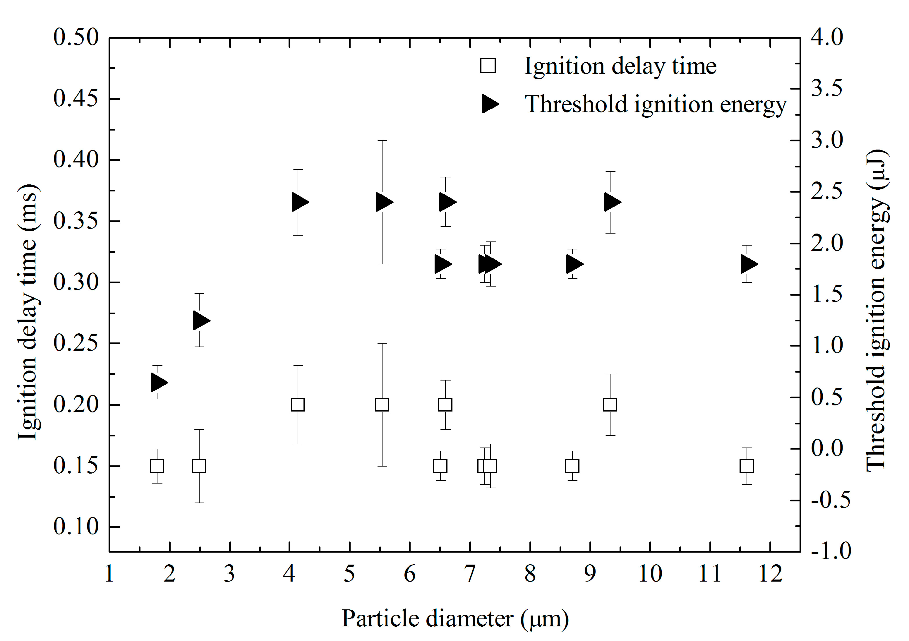
3.1.3. Effect of Particle Diameter on Ignition Delay and Threshold Energy

In this work, the effect of graphite diameter on its ignition delay and threshold of ignition energy were examined. The results are shown in Figure 8. The micron-sized graphite particles ranging from 1.0 μm to 12.0 μm were ignited with a delay of 0.15~0.20 ms. Considering the uncertainty of measurement, the ignition delay time was almost the same, and was scarcely affected by the particle diameter.
The beam diameter highly focused by the objective was ~3.0 μm, and the power density was about 1.33 × 10⁹ W/m2. For the graphite particles whose diameters were larger than the focused beam diameter, the locally illuminated zone at the graphite surface was quickly heated. However, in the transverse, the heat could not propagate in such a short time due to a low thermal conductivity of 129 W/(m·K). This led to a high temperature rise in the illuminated region. For the graphite particles whose diameters were smaller than the focused beam diameter, although the graphite particles were encircled to heat, the aspheric surface and tiny impurities of particles possibly had non-uniformly temperature distribution. Therefore, the graphite microparticles were heterogeneously ignited by the highly focused laser beam with the same delay time.
Figure 8 shows that the threshold ignition energy increases with increasing the particle diameter, as the graphite particle was smaller than the focused beam diameter (3.0 μm). This suggests that the smaller the particle size is, the larger the surface area-to-volume ratio becomes, resulting in lower activity energy and ignition energy. As the graphite particle was larger than the focused beam diameter, the threshold ignition energy ranged from 1.8 μJ to 2.4 μJ. The particle diameter had a small weak effect on the threshold ignition energy.

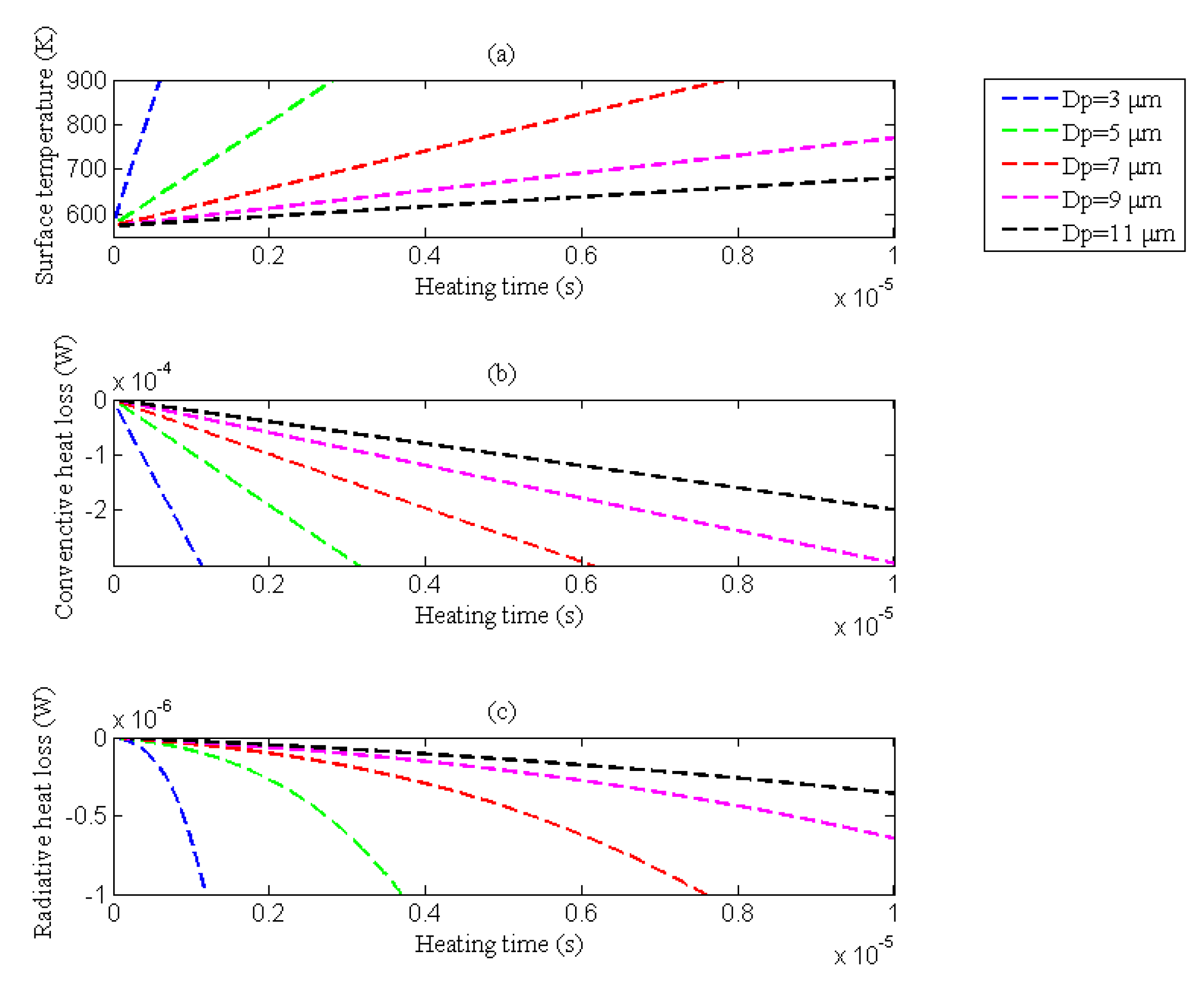
3.1.4. Influence of the Wall Heat Loss on the Ignition

The cool wall of the micro-combustor would result in a large heat loss [14], possibly influencing the ignition delay time and threshold ignition energy. According to our previous work [24], the wall had a similar temperature rise trend as the microparticle directly lying at the bottom wall of the micro-combustor, which was heated by laser. The temperature difference between the microparticle and the combustor wall gradually increases with the increase of microparticle temperature. Thus, the combustor wall heat loss could not be neglected owing to the heat exchange from the graphite microparticle to the wall during heating.

3.2. Combustion

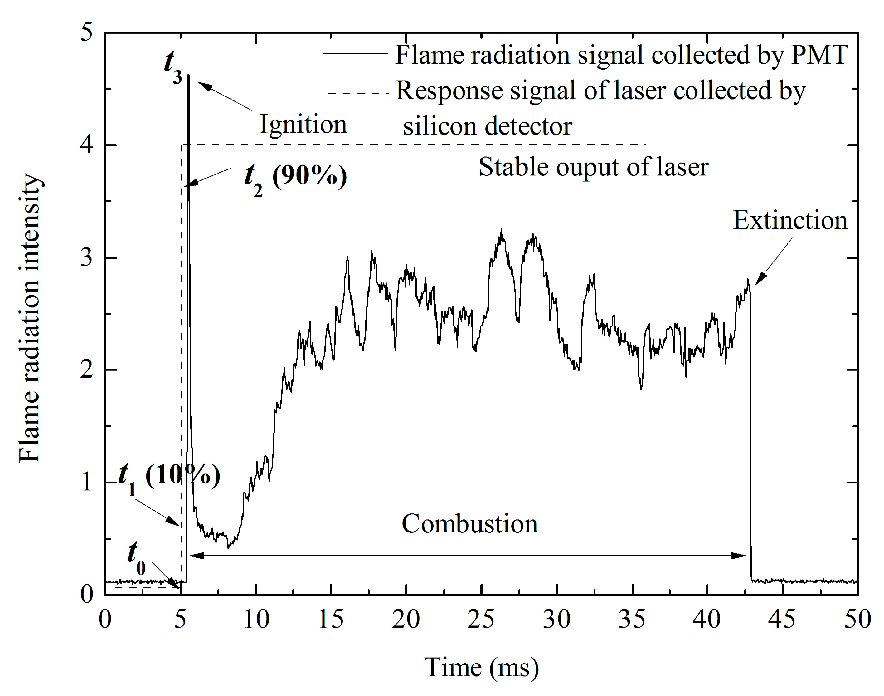
3.2.1. Combustion Stages

At the microscale, the large heat loss and the strong flame-wall structure thermal and kinetic coupling result in flame instability such as the repetitive ignition and extinction [25,26,27]. Figure 7 shows that, at natural convection and room temperature, the radiation intensity first increased, then abruptly decreased, and again increased and oscillated to become abruptly extinct, indicating the heating, ignition, instability combustion and extinction of graphite. In this case, the convective and radiative heat losses were considerable, compared with the heat of reaction. Therefore, the flame was instable, and the flame radiation intensity oscillated with a frequency of 7.8 KHz.

3.2.2. Flame Structure

Figure 6 demonstrates the burning sequence of an individual micron-sized graphite particle with the equivalent diameter of 4.16 μm. The flame was weak at the initial burning stage (Figure 6a). The envelop flame of graphite combustion became brighter gradually as the oxidation of graphite accelerated (Figure 6b–e). Simultaneously, the combustion flame front diffused quickly. The flame structure was asymmetric. In Figure 6e, the flame structure looked like a comet. The phenomenon is called delayed combustion, suggesting that the surface of graphite is mainly oxidized as carbon monoxide at the initial stage. Carbon monoxide takes the next step reaction with the diffusive oxygen from the gas film near the carbon surface, leading to the generation of carbon dioxide. Carbon monoxide encircles the graphite particle, and diffuses outward to the surrounding atmosphere, resulting in the occurrence of homogeneous combustion. The relative quantities of CO and CO2 formed in oxidation and the effective heat of reaction per mole of carbon consumed can be calculated by the oxygen stoichiometric coefficient in the carbon conversion reaction. During combustion of carbon, CO2 can also play a role of oxidizer at the surface reaction. This means that the oxygen concentration in the oxidizer flow can further be reduced by increasing CO2 concentration.

3.2.3. Flame Front

The evolution history of the flame front is shown in Figure 9, including flame extension, fluctuation and suppression. After ignition, the flame front extended toward the surrounding air with an averaged velocity of 1.21 mm/s. Before extinction, the flame front suppressed toward the graphite surface with an averaged velocity of ~1.28 mm/s. The flame extension velocity was almost equal to the suppression velocity, suggesting that the naturally diffusive velocity of oxygen remained stable and the oxidation reaction depended on oxygen diffusion control.

3.2.4. Crystalline Structure of Graphite after Combustion

After combustion, some graphite powders were collected and tested by XRD. The XRD spectrum of burned graphite, as shown in Figure 3, had the same pattern as the unburned graphite. At low temperatures, the chemically controlled reactions are so slow that the oxygen can penetrate the graphite in depth, causing rather uniform attack and thus affecting the thermal physical properties without changing the graphite geometry. At high temperatures, the diffusively controlled reactions are so high that the oxygen penetrating the laminar boundary layer near the hot graphite reacts immediately at the surface. The oxidation induces geometry changes of the graphite body without damaging the deeper material. This indicates that, during combustion, the oxidization reaction occurs at the surface of graphite, and scarcely affects the crystalline form of unburned carbon [28].

3.3. Photophoresis

As soon as a graphite particle is illuminated by laser, absorption, reflection, refraction and diffraction occur at the surface of the particle. Simultaneously, the surface of the particle is heated unevenly along the optical axis by laser radiation. The gas molecule collisions on the particle surface would result in a small photophoretic force. In general, for strong absorbent particles, more absorption can occur on the illuminated side, which leads to positive photophoresis. However, if the wavelength of illuminating irradiation has the same order as the particle diameter, illumination performs negative photophoresis, and even strong absorbent particles are transparent [29].
Experimental observations showed that the graphite particle illuminated by the laser beam moved inversely towards the focal point due to the negative photophoretic force. This possibly meant that the graphite particles could not be ignited. During combustion, the graphite particles possibly move, as shown in Figure 10. The equivalent diameter of the graphite particle is 4.13 μm. The graphite particle was ignited, and then a bright flame was clearly observed in Figure 10b. However, the graphite particle was repelled from the laser focus (Figure 10c). The repelled velocity was ~446.7 μm/s. Owing to the drift, the whole graphite particle was not located in the laser focus, so the flame quenched in cool air at once.
The photophoretic force relates to the temperature difference or accommodation coefficient difference over the particle surface. They are called the ΔT force and Δα force, respectively. The ΔT force, caused by inhomogeneous heating, is in its nature a radiometric force. It is the positive or negative force of longitudinal photophoresis. It is strongly dependent on pressure. The Δα force, which is strongly dependent on the surface properties, points from the higher accommodation coefficient side to the lower accommodation coefficient side [30].
During ignition or during combustion, the drift event of the graphite particle resulted from the increase of ΔT force and Δα force. The inhomogeneous heating and heterogeneous combustion of the graphite particle made its temperature distribution nonuniform. The overall temperature of the particle was higher than the air temperature. The ΔT and Δα force would increase with the increase of the particle temperature.

3.4. Repetitive Extinction and Reignition

Figure 11 shows another burning sequence and time history of an individual micron-sized graphite particle with the equivalent diameter of 1.79 μm. The graphite was ignited with the delay of 0.15 ms, and it burned for 672 ms. In Figure 11b, although the particle diameter is smaller than the focused laser beam, it can be testified that the ignition mode of graphite is heterogeneous. During combustion, two extinctions were observed at 156 ms and 432 ms (Figure 11e,i). Generally, at the microscale, the temperature and reactivity of weak flames are stabilized and low [31,32,33]. However, owing to insufficient heat generation and large heat loss inside the micro-combustor, the flame quenches. Under the assistance of the laser, two reignitions of graphite followed the extinctions (Figure 11f,j). The flame interaction between the thermal and chemical surface led to flame quenching and made the flames bifurcated (Figure 11c). At the microscale, such flames were also observed under the gas-solid thermal coupling in particle laden flames and strained flames under the combined effects of radiation and unequal diffusive-thermal transport [34].

4. Conclusions

Ignition and burning behavior of individual micron-sized graphite particles in a micro-combustor were investigated. One emphasis was to investigate laser-induced ignition behavior of individual micron-sized graphite particle in a limited space. The other emphasis was to discover possible new combustion phenomena and burning behavior owing to large heat loss of the combustor wall, including photophoresis, repetitive extinction and reignition. In the present work, some conclusions were made as following.
(1)
The micron-sized graphite particles scattered in the micro-combustor were heterogeneously ignited by laser. The particle diameter scarcely influenced the threshold ignition energy and the ignition delay time. After combustion, the crystalline structure of graphite had the same pattern as the unburned graphite.
(2)
The combustion radiation intensity first increased, then abruptly decreased, and again increased and oscillated to become abruptly extinct. The envelop flame front diffused quickly, and the flame became brighter. After oscillating combustion, the envelop flame front suppressed. The extension and suppression velocities of the flame were almost equivalent.
(3)
During combustion, the graphite particle suffered the negative photophoretic force and moved far from the focal point of the laser, resulting in extinction.
(4)
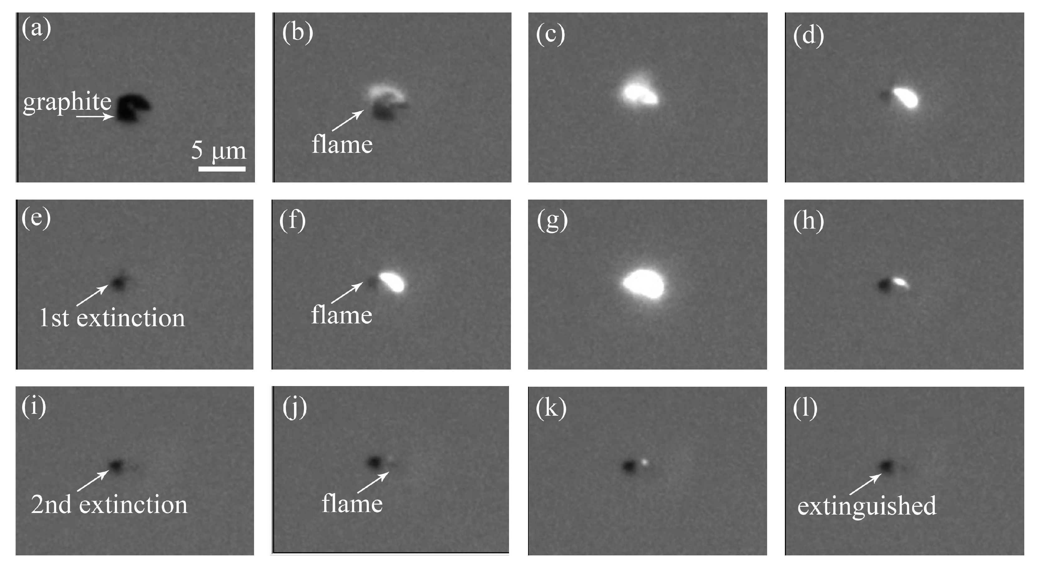
The heat loss of the micro-combustor wall had a significant effect on the ignition and combustion. The flame bifurcations, weak flame, repetitive extinction and reignition of the graphite in limited space could be clearly recognized.

Author Contributions

Conceptualization, X.H. and S.L.; methodology, X.H.; investigation, Y.W., M.Z., S.C., S.L., and X.H.; data curation, M.Z. and S.C.; Writing—original draft, Y.W.; Writing—review & editing, S.L. and X.H. All authors have read and agreed to the published version of the manuscript.

Funding

This work was financially supported by the National Natural Science Foundation of China (51976050), the Natural Science Foundation of Zhejiang Province (LY20E060004), and the Fundamental Research Funds for the Provincial Universities of Zhejiang (GK209907299001-004).

Conflicts of Interest

The authors declare no conflict of interest.

References

  1. Smith, I.W. The combustion rates of coal chars: A review. Symp. (Int.) Combust. 1982, 19, 1045–1065. [Google Scholar] [CrossRef]
  2. Abuelnuor, A.A.A.; Wahid, M.A.; Hosseini, S.E.; Saat, A.; Saqr, K.M.; Sait, H.H.; Osman, M. Characteristics of biomass in flameless combustion: A review. Renew. Sustain. Energy Rev. 2014, 33, 363–370. [Google Scholar] [CrossRef]
  3. Zhou, H.; Meng, A.H.; Long, Y.Q.; Li, Q.H.; Zhang, Y.G. An overview of characteristics of municipal solid waste fuel in China: Physical, chemical composition and heating value. Renew. Sustain. Energy Rev. 2014, 36, 107–122. [Google Scholar] [CrossRef]
  4. Thomas, J.M. Reactivity of carbon: Some current problems and trends. Carbon 1970, 8, 413–421. [Google Scholar] [CrossRef]
  5. Valerio, C.; Luigi, P.; Sandro, P. Ignition and combustion of individual, levitated char particles. Combust. Flame 1995, 103, 181–193. [Google Scholar]
  6. Solís-Fernández, P.; Paredes, J.I.; Cosío, A.; Martínez-Alonso, A.; Tascón, J.M.D. A comparison between physically and chemically driven etching in the oxidation of graphite surfaces. J. Colloid Interface Sci. 2010, 344, 451–459. [Google Scholar] [CrossRef]
  7. Stevens, F.; Beebe, T.P. Computer modeling of graphite oxidation: Differences between monolayer and multilayer etching. Comput. Chem. 1999, 23, 175–183. [Google Scholar] [CrossRef]
  8. Qu, M.; Ishigaki, M.; Tokuda, M. Ignition and combustion of laser-heated pulverized coal. Fuel 1996, 75, 1155–1160. [Google Scholar] [CrossRef]
  9. Makino, A.; Namikiri, T.; Kimura, K. Combustion rates of graphite rods in the forward stagnation field with high-temperature airflow. Combust. Flame 2003, 132, 743–753. [Google Scholar] [CrossRef]
  10. Stauch, R.; Maas, U. Transient detailed numerical simulation of the combustion of carbon particles. Int. J. Heat Mass Tranf. 2009, 52, 4584–4591. [Google Scholar] [CrossRef]
  11. Makino, A.; Kato, I.; Senba, M.; Fujizaki, H.; Araki, N. Flame structure and combustion rate of burning graphite in the stagnation flow. Symp. (Int.) Combust. 1996, 26, 3067–3074. [Google Scholar] [CrossRef]
  12. Makino, A.; Fujizaki, H.; Araki, N. Combustion Rate of Burning Graphite in a Stagnation Flow of Water Vapor. Combust. Flame 1998, 113, 258–263. [Google Scholar] [CrossRef]
  13. Makino, A.; Umehara, N. Combustion rates of graphite rods in the forward stagnation field of the high-temperature, humid airflow. Proc. Combust. Inst. 2007, 31, 1873–1880. [Google Scholar] [CrossRef]
  14. Maruta, K. Micro and mesoscale combustion. Proc. Combust. Inst. 2011, 33, 125–150. [Google Scholar] [CrossRef]
  15. Ju, Y.G.; Maruta, K. Microscale combustion: Technology development and fundamental research. Prog. Energy Combust. Sci. 2011, 37, 669–715. [Google Scholar] [CrossRef]
  16. Delhaes, P. Graphite and Precursors; CRC Press: Boca Raton, FL, USA, 2001; pp. 40–50. ISBN 90-5699-228-7. [Google Scholar]
  17. Li, S.J.; Huang, X.F. The manipulation and combustion of carbon-based micro particles by optical tweezers. Int. J. Optomechatron. 2015, 9, 35–47. [Google Scholar] [CrossRef] [Green Version]
  18. Li, S.; Huang, X.; Zhou, D. Experiments and Numerical Calculations on Laser-Induced Ignition of Single Micron-Sized Aluminum Fuel Particle. Propellants Explos. Pyrotech. 2017, 42, 523–531. [Google Scholar] [CrossRef]
  19. Huang, X.; Li, S.; Zheng, X.; Yang, S.; Guo, Y. Combustion Mechanism of a Novel Energetic Fuel Candidate Based on Amine Metal Borohydrides. Energy Fuel 2016, 30, 1383–1389. [Google Scholar] [CrossRef]
  20. Essenhigh, R.H.; Misra, M.K.; Shaw, D.W. Ignition of coal particle: A review. Combust. Flame 1989, 77, 3–30. [Google Scholar] [CrossRef]
  21. Effron, E.; Hoelscher, H.E. Graphite oxidation at low temperature. AIChE J. 1964, 10, 388–392. [Google Scholar] [CrossRef]
  22. Gulbransen, E.A.; Andrew, K.F.; Brassart, F.A. The Oxidation of Graphite at Temperatures of 600° to 1500 °C and at Pressures of 2 to 76 Torr of Oxygen. J. Electrochem. Soc. 1963, 110, 476–483. [Google Scholar] [CrossRef]
  23. Arthur, J.R. Reactions between carbon and oxygen. Trans. Faraday Soc. 1951, 47, 164–178. [Google Scholar] [CrossRef]
  24. Hou, F.; Li, S.; Wang, Y.; Huang, X. Laser-Induced Ignition and Combustion of Individual Aluminum Particles below 10 μm by Microscopic High-Speed Cinematography. Processes 2020, 8, 280. [Google Scholar] [CrossRef] [Green Version]
  25. Richecoeur, F.; Kyritsis, D.C. Experimental study of flame stabilization in low Reynolds and Dean number flows in curved mesoscale ducts. Proc. Combust. Inst. 2005, 30, 2419–2427. [Google Scholar] [CrossRef]
  26. Miesse, C.; Masel, R.I.; Short, M.; Shannon, M.A. Diffusion flame instabilities in a 0.75 mm non-premixed microburner. Proc. Combust. Inst. 2005, 30, 2499–2507. [Google Scholar] [CrossRef]
  27. Xu, B.; Ju, Y. Studies on non-premixed flame streets in a mesoscale channel. Proc. Combust. Inst. 2009, 32, 1375–1382. [Google Scholar] [CrossRef]
  28. Snead, L.; Burchell, T. Oxidation of High-Quality Graphite for IFE. In Proceedings of the 3rd Laser IFE Program Workshop, San Diego, CA, USA, 13–14 November 2001; pp. 1–9. [Google Scholar]
  29. Jovanovic, O. Photophoresis-Light induced motion of particles suspended in gas. J. Quant. Spectrosc. Radiat. Transf. 2009, 110, 889–901. [Google Scholar] [CrossRef]
  30. Wurm, G.; Krauss, O. Experiments on negative photophoresis and application to the atmosphere. Atmos. Environ. 2008, 42, 2682–2690. [Google Scholar] [CrossRef]
  31. Mikami, M.; Kojima, N. An experimental and modeling study on stochastic aspects of microexplosion of binary-fuel droplets. Proc. Combust. Inst. 2002, 29, 551–559. [Google Scholar] [CrossRef]
  32. Tsuboi, Y.; Yokomori, T.; Maruta, K. Lower limit of weak flame in a heated channel. Proc. Combust. Inst. 2009, 32, 3075–3081. [Google Scholar] [CrossRef]
  33. Oshibe, H.; Nakamura, H.; Tezuka, T.; Hasegawa, S.; Maruta, K. Stabilized three stage oxidation of DME/air mixture in a micro flow reactor with a controlled temperature profile. Combust. Flame 2010, 157, 1572–1580. [Google Scholar] [CrossRef]
  34. Kim, K.T.; Lee, D.H.; Kwon, S. Effects of thermal and chemical surface-flame interaction on flame quenching. Combust. Flame 2006, 146, 19–28. [Google Scholar] [CrossRef]
Figure 1. SEM (scanning electron microscopy) morphology of graphite powders.
Processes 08 01493 g001
Figure 2. EDS (Energy dispersive spectrometer) morphology of graphite powders.
Processes 08 01493 g002
Figure 3. XRD (X-ray diffraction) patterns of graphite particles before and after combustion.
Processes 08 01493 g003
Figure 4. Experimental setup.
Processes 08 01493 g004
Figure 5. The calculated curves of temperature rise (heating rate) and convective and radiative heat losses of graphite under laser radiation absorption. (a) Surface temperature rise; (b) Convective heat loss; (c) Radiative heat loss.
Processes 08 01493 g005
Figure 6. A burning sequence and flame structure of an individual micron-sized graphite particle, (a) 0 ms; (b) 6 ms; (c) 30 ms; (d) 36 ms; (e) 42 ms; (f) 48 ms.
Processes 08 01493 g006
Figure 7. The curves are used to measure the ignition delay time of individual micron-sized graphite particles. The solid line shows the history of flame radiation intensity of the individual micron-sized graphite particles during combustion, which was acquired by the PMT (photomultiplier tube). The dashed line presents the history of the laser beam from turning it on to its stable output, which was acquired by a silicon detector.
Processes 08 01493 g007
Figure 8. Ignition delay time and threshold ignition energy of graphite at microscale.
Processes 08 01493 g008
Figure 9. The flame front evolution during the combustion of the graphite particle.
Processes 08 01493 g009
Figure 10. Photophoresis of the graphite particle during combustion, (a) 0 ms; (b) 6 ms; (c) 12 ms; (d) 18 ms.
Processes 08 01493 g010
Figure 11. A burning sequence and time history of repetitive extinction and reignition of a graphite particle, (a) 0 ms; (b) 6 ms; (c) 12 ms; (d) 144 ms; (e) 156 ms; (f) 162 ms; (g) 168 ms; (h) 198 ms; (i) 432 ms; (j) 456 ms; (k) 492 ms; (l) 672 ms.
Processes 08 01493 g011
Publisher’s Note: MDPI stays neutral with regard to jurisdictional claims in published maps and institutional affiliations.

