Study of a Method to Effectively Remove Char Byproduct Generated from Fast Pyrolysis of Lignocellulosic Biomass in a Bubbling Fluidized Bed Reactor


Abstract
:1. Introduction
2. Materials and Methods
2.1. Materials
2.2. Methods
2.3. Analyses
3. Results and Discussion
3.1. Distribution of Product
3.2. Characterization of Products
4. Conclusions
Author Contributions
Funding
Conflicts of Interest
References
- Bauen, A.; Berndes, G.; Junginger, M.; Londo, M.; Vuille, F. Bioenergy—A sustainable and reliable energy source, A review of status and prospects. IEA Bioenergy Annu. Rep. 2009, 5, 108. [Google Scholar]
- Saidur, R.; Abdelaziz, E.A.; Demirbas, A.; Hossain, M.S.; Mekhilef, S. A review on biomass as a fuel for boilers. Renew. Sustain. Energy Rev. 2011, 15, 2262–2289. [Google Scholar] [CrossRef]
- Tillman, D.A. Biomass cofiring: The technology, the experience, the combustion consequences. Biomass Bioenergy 2000, 19, 365–384. [Google Scholar] [CrossRef]
- Míguez, J.L.; Morán, J.C.; Granada, E.; Porteiro, J. Review of technology in small-scale biomass combustion systems in the European market. Renew. Sustain. Energy Rev. 2012, 16, 3867–3875. [Google Scholar] [CrossRef]
- Panwar, N.L.; Kothari, R.; Tyagi, V.V. Thermo chemical conversion of biomass—Eco friendly energy routes. Renew. Sustain. Energy Rev. 2012, 16, 1801–1816. [Google Scholar] [CrossRef]
- Bridgwater, A.V.; Peacocke, G.V.C. Fast pyrolysis processes for biomass. Renew. Sustain. Energy Rev. 2000, 4, 1–73. [Google Scholar] [CrossRef]
- Huang, H.; Yuan, X. Review: Recent progress in the direct liquefaction of typical biomass. Prog. Energy Combust. Sci. 2015, 49, 59–80. [Google Scholar] [CrossRef]
- Ahmad, A.A.; Zawawi, N.A.; Kasim, F.H.; Inayat, A.; Khasri, A. Assessing the gasification performance of biomass: A review on biomass gasification process conditions, optimization and economic evaluation. Renew. Sustain. Energy Rev. 2016, 53, 1333–1347. [Google Scholar] [CrossRef]
- Swain, P.K.; Das, L.M.; Naik, S.N. Biomass to liquid: A prospective challenge to research and development in 21st century. Renew. Sustain. Energy Rev. 2011, 15, 4917–4933. [Google Scholar] [CrossRef]
- Trippe, F.; Fröhling, M.; Schultmann, F.; Stahl, R.; Henrich, E.; Dalai, A. Comprehensive techno-economic assessment of dimethyl ether (DME) synthesis and Fischer-Trospsch synthesis as alternative process steps within biomass-to-liquid production. Fuel Process. Technol. 2013, 106, 577–586. [Google Scholar] [CrossRef]
- Elliott, D.C.; Biller, P.; Ross, A.B.; Schmidt, A.J.; Jones, S.B. Hydrothermal liquefaction of biomass: Developments from batch to continuous process. Bioresour. Technol. 2015, 178, 147–156. [Google Scholar] [CrossRef] [PubMed] [Green Version]
- Kan, T.; Strezov, V.; Evans, T.J. Lignocellulosic biomass pyrolysis: A review of product properties and effects of pyrolysis parameters. Renew. Sustain. Energy Rev. 2016, 57, 1126–1140. [Google Scholar] [CrossRef]
- Lu, Q.; Li, W.Z.; Zhu, X.F. Overview of fuel properties of biomass fast pyrolysis oils. Energy Convers. Manag. 2009, 50, 1376–1383. [Google Scholar] [CrossRef]
- Lehto, J.; Oasmaa, A.; Solantausta, Y.; Kytö, M.; Chiaramonti, D. Review of fuel oil quality and combustion of fast pyrolysis bio-oils from lignocellulosic biomass. Appl. Energy 2014, 116, 178–190. [Google Scholar] [CrossRef]
- Czernik, S.; Bridgwater, A.V. Overview of applications of biomass fast pyrolysis oil. Energy Fuels 2004, 18, 590–598. [Google Scholar] [CrossRef]
- No, S.Y. Application of bio-oils from lignocellulosic biomass to transportation, heat and power generation—A review. Renew. Sustain. Energy Rev. 2014, 40, 1108–1125. [Google Scholar] [CrossRef]
- Mercader, F.D.M.; Groeneveld, M.J.; Kersten, S.R.A.; Venderbosh, R.H.; Hogendoorn, J.A. Pyrolysis oil upgrading by high pressure thermal treatment. Fuel 2010, 89, 2829–2837. [Google Scholar] [CrossRef]
- Patel, M.; Kumar, A. Production of renewable diesel through the hydroprocessing of lignocellulosic biomass-derived bio-oil: A review. Renew. Sustain. Energy Rev. 2016, 58, 1293–1307. [Google Scholar] [CrossRef]
- Rezaei, P.S.; Shafaghat, H.; Daud, W.M.A.W. Production of green aromatics and olefins by catalytic cracking of oxygenate compounds derived from biomass pyrolysis: A review. Appl. Catal. A Gen. 2014, 469, 490–511. [Google Scholar] [CrossRef]
- Bahng, M.K.; Mukarakate, C.; Robichaud, D.J.; Nimlos, M.R. Current technologies for analysis of biomass thermochemical processing: A review. Anal. Chim. Acta 2009, 651, 117–138. [Google Scholar] [CrossRef]
- Ishak, W.N.R.W.; Hisham, M.W.M.; Yarmo, M.A.; Hin, T.Y. A review on bio-oil production from biomass by using pyrolysis method. Renew. Sustain. Energy Rev. 2012, 16, 5910–5923. [Google Scholar] [CrossRef]
- Vardiambasis, I.O.; Kapetanakis, T.N.; Nikolopoulos, C.D.; Trang, T.K.; Tsubota, T.; Keyikoglu, R.; Khataee, A.; Kalderis, D. Hydrochars as emerging biofuels: Recent advances and application of artificial neural networks for the prediction of heating values. Energies 2020, 13, 4572. [Google Scholar] [CrossRef]
- Venderboasch, R.H.; Prins, W. Fast pyrolysis technology development. Biofuels Bioprod. Biorefin. 2010, 4, 178–208. [Google Scholar] [CrossRef]
- Solantausta, Y.; Oasmaa, A.; Sipilar, K.; Lindfors, C.; Lehto, J.; Autio, J.; Jokela, P.; Alin, J.; Heiskanen, J. Bio-oil production from biomass: Steps toward demonstration. Energy Fuels 2012, 26, 233–240. [Google Scholar] [CrossRef]
- Karmee, S.K.; Kumari, G.; Soni, B. Pilot scale oxidative fast pyrolysis of sawdust in a fluidized bed reactor: A biorefinery approach. Bioresour. Technol. 2020, 318, 124071. [Google Scholar] [CrossRef]
- Chen, B.; Han, X.; Tong, J.; Mu, M.; Jiang, X.; Wang, S.; Shen, J.; Ye, X. Studies of fast co-pyrolysis of oil shale and wood in a bubbling fluidized bed. Energy Convers. Manag. 2020, 205, 112356. [Google Scholar] [CrossRef]
- Santamaria, L.; Beirow, M.; Mangold, F.; Lopez, G.; Olazar, M.; Schmid, M.; Li, Z.; Scheffknecht, G. Influence of temperature on products from fluidized bed pyrolysis of wood and solid recovered fuel. Fuel 2021, 283, 118922. [Google Scholar] [CrossRef]
- Xianwen, D.; Chuangzhi, W.; Haibin, L.; Yong, C. The fast pyrolysis of biomass in CFB reactor. Energy Fuels 2000, 14, 552–557. [Google Scholar] [CrossRef]
- Park, J.Y.; Kim, J.K.; Oh, C.H.; Park, J.W.; Kwon, E.E. Production of bio-oil from fast pyrolysis of biomass using a pilot-scale circulating fluidized bed reactor and its characterization. J. Environ. Manag. 2019, 234, 138–144. [Google Scholar] [CrossRef]
- Dupont, C.; Commandré, J.M.; Gauthier, P.; Boissonnet, G.; Salvador, S.; Schweich, D. Biomass pyrolysis experiments in an analytical entrained flow reactor between 1073 K and 1273 K. Fuel 2008, 87, 1155–1164. [Google Scholar] [CrossRef] [Green Version]
- Ashcraft, R.W.; Heynderickx, G.J.; Marin, G.B. Modeling fast biomass pyrolysis in a gas-solid vortex reactor. Chem. Eng. J. 2012, 207, 195–208. [Google Scholar] [CrossRef] [Green Version]
- Johansson, A.C.; Wiinikka, H.; Sandström, L.; Marklund, M.; Öhrman, O.G.W.; Narvesjö, J. Characterization of pyrolysis products produced from different Nordic biomass types in a cyclone pilot plant. Fuel Process. Technol. 2016, 146, 9–19. [Google Scholar] [CrossRef]
- Trinh, T.N.; Jensen, P.A.; Sárossy, Z.; Dam-Johansen, K.; Knudsen, N.O.; Sørensen, H.R.; Egsgaard, H. Fast pyrolysis of lignin using a pyrolysis centrifuge reactor. Energy Fuels 2013, 27, 3802–3810. [Google Scholar] [CrossRef]
- Gable, P.; Brown, R.C. Effect of biomass heating time on bio-oil yields in a free fall fast pyrolysis reactor. Fuel 2016, 166, 361–366. [Google Scholar] [CrossRef]
- Li, J. The optimal of pyrolysis process in the rotating cone reactor and pyrolysis product analysis. In Proceedings of the International Conference on Challenges in Environmental Science and Computer Engineering, SESCE 2010, Wuhan, China, 6–7 March 2010; Volume 1, pp. 530–533. [Google Scholar]
- Luz, F.C.; Cordiner, S.; Manni, A.; Mulone, V.; Rocco, V. Biomass fast pyrolysis in screw reactors: Prediction of spent coffee grounds bio-oil production through a monodimensional model. Energy Convers. Manag. 2018, 168, 98–106. [Google Scholar]
- Park, H.J.; Park, Y.K.; Kim, J.S. Influence of reaction conditions and the char separation system on the production of bio-oil from radiate pine sawdust by fast pyrolysis. Fuel Process. Technol. 2008, 89, 797–802. [Google Scholar]
- Muley, P.D.; Henkel, C.; Abdollahi, K.K.; Marculescu, C.; Boldor, D. A critical comparison of pyrolysis of cellulose, lignin, and pine sawdust using an induction heating reactor. Energy Convers. Manag. 2016, 117, 273–280. [Google Scholar] [CrossRef] [Green Version]
- Klemetsrud, B.; Eatherton, D.; Shonnard, D. Effects of lignin content and temperature on the properties of hydrid poplar bio-oil, char, and gas obtained by fast pyrolysis. Energy Fuels 2017, 31, 2879–2886. [Google Scholar] [CrossRef]
- Zhou, S.; Pecha, B.; Kuppevelt, M.V.; McDonald, A.G.; Garcia-Perez, M. Slow and fat pyrolysis of Douglas-fir lignin: Importance of liquid-intermediate formation on the distribution of products. Biomass Bioenergy 2014, 6, 398–409. [Google Scholar] [CrossRef]
- Azargohar, R.; Nanda, S.; Kozinski, J.A.; Dalai, A.K.; Sutarto, R. Effects of temperature on the physicochemical characteristics of fast pyrolysis bio-chars derived from Canadian waste biomass. Fuel 2014, 125, 90–100. [Google Scholar] [CrossRef]


| Proximate Analysis a (wt%) | Ultimate Analysis b (wt%) | Heating Value c (MJ/kg) | ||||||||
|---|---|---|---|---|---|---|---|---|---|---|
| M | VM | FC | Ash | C | H | N | S | O d | HHV | LHV |
| 9.7 | 73.7 | 16.0 | 0.5 | 45.5 | 7.0 | 0.6 | 0.002 | 46.9 | 17.9 | 16.1 |
| Pyrolysis Temperature (°C) at 0.84 kg/h Feeding Rate | Sawdust Feeding Rate (kg/h) at 440 °C | |||||||
|---|---|---|---|---|---|---|---|---|
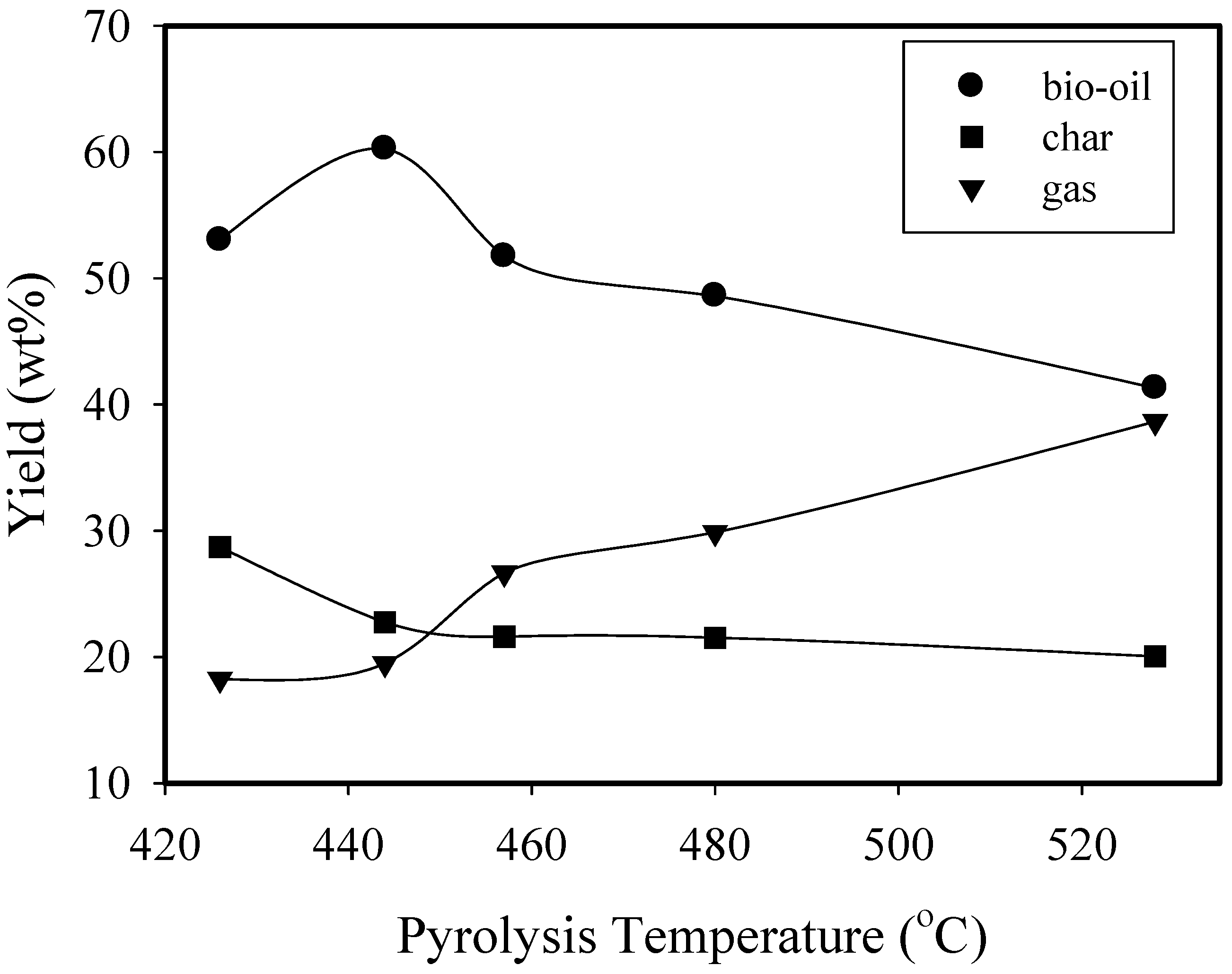
| 426 | 444 | 457 | 480 | 528 | 0.84 | 1.32 | 1.77 | |
| Yield (wt%) | 53.0 | 60.3 | 51.7 | 48.1 | 41.3 | 60.3 | 62.4 | 62.2 |
| Elemental comp. (wt%) | ||||||||
| C | 34.2 | 43.2 | 39.3 | 41.3 | 32.3 | 43.2 | 40.1 | 39.9 |
| H | 9.1 | 10.1 | 10.1 | 9.8 | 9.1 | 10.1 | 9.9 | 9.8 |
| N | 0.9 | 1.2 | 0.9 | 0.9 | 0.9 | 1.2 | 0.9 | 0.1 |
| O a | 55.8 | 45.5 | 49.7 | 48.0 | 57.7 | 45.5 | 49.1 | 50.2 |
| O/C (mol/mol) | 1.22 | 0.79 | 0.95 | 0.87 | 1.34 | 0.79 | 0.92 | 0.94 |
| H/C (mol/mol) | 3.19 | 2.81 | 3.08 | 2.85 | 3.38 | 2.81 | 2.96 | 2.95 |
| Water content (wt%) | 36.4 | 35.4 | 36.8 | 30.7 | 49.2 | 35.4 | 34.5 | 40.6 |
| HHV (MJ/kg) | 17.12 | 17.46 | 17.12 | 17.12 | 17.12 | 17.46 | 16.79 | 16.87 |
| TOC (g/L) | 384.6 | 383.6 | 366.5 | 410.6 | 310.5 | 383.6 | 404.9 | 364.1 |
| COD (gO2/L) | 1328 | 1216 | 1344 | 1288 | 1336 | 1216 | 1208 | 1144 |
| pH | 1.8 | 1.9 | 2.0 | 1.9 | 2.3 | 1.9 | 1.8 | 1.8 |
| No. | RT | Compound | Area (%) | |
|---|---|---|---|---|
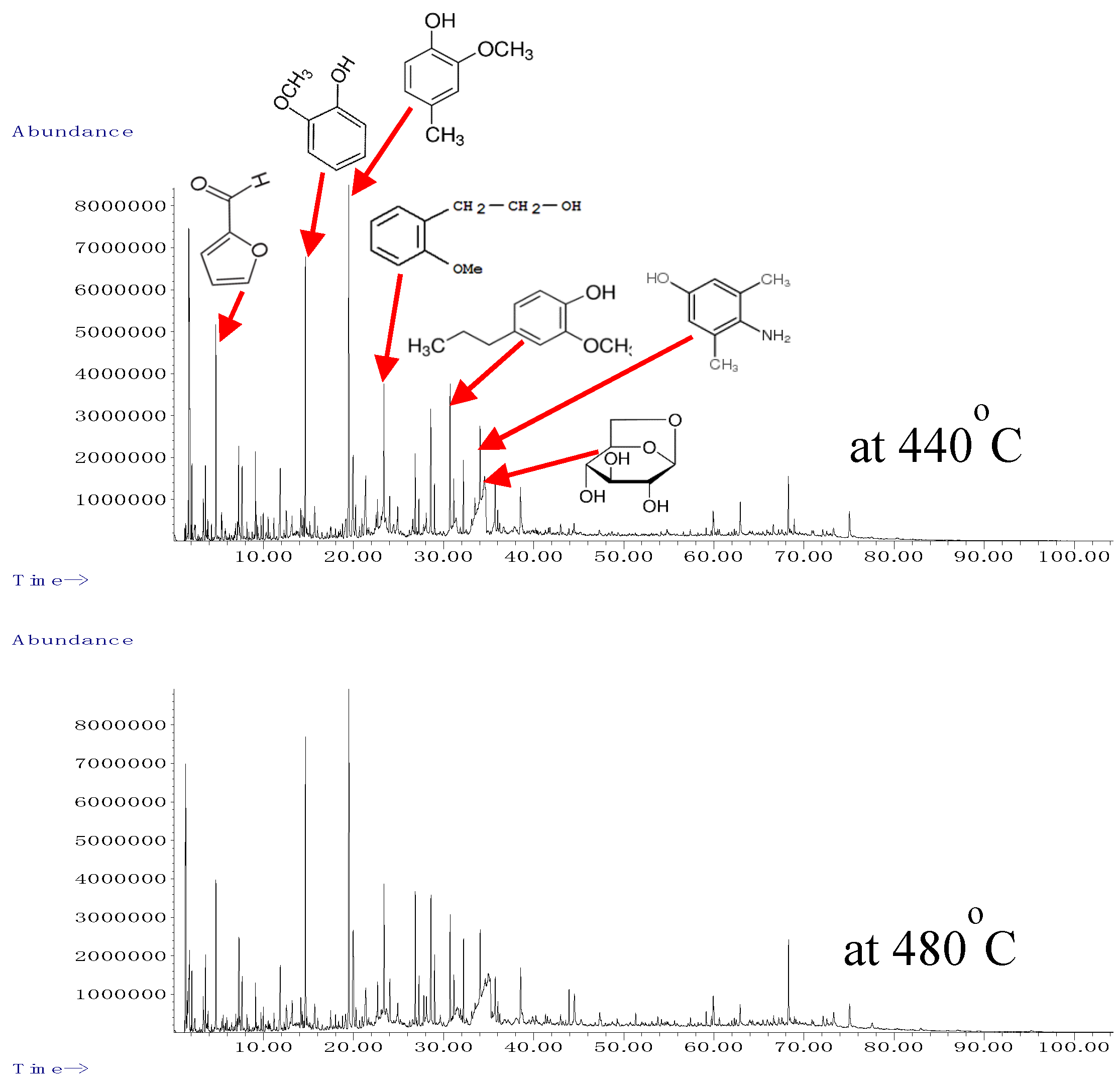
| (min) | 440 °C | 480 °C | ||
| 1 | 4.722 | Furfural | 2.48 | 2.20 |
| 2 | 7.269 | 2(5H)-Furanone | 1.77 | 2.24 |
| 3 | 7.658 | 1,2-Cyclopentanedione | 1.99 | 1.44 |
| 4 | 9.111 | Furfural, 5-methyl- | 1.09 | 0.71 |
| 5 | 11.875 | 2-Cyclopenten-1-one, 2-hydroxy-3-methyl- | 1.82 | 1.92 |
| 6 | 12.533 | 4-Methyl-5H-furan-2-one | 0.73 | 0.87 |
| 7 | 14.147 | Phenol, 4-methyl- | 0.75 | 0.73 |
| 8 | 14.662 | Phenol, 2-methoxy- (guaiacol) | 4.62 | 5.45 |
| 9 | 15.692 | Maltol | 0.98 | 0.77 |
| 10 | 19.176 | 4H-Pyran-4-one, 3,5-dihydroxy-2-methyl- | 0.88 | 0.58 |
| 11 | 19.480 | Phenol, 2-methoxy-4-methyl- (cresol) | 6.90 | 7.41 |
| 12 | 19.954 | 1,2-Benzenediol | 2.92 | 3.86 |
| 13 | 20.241 | 1,4:3,6-Dianhydro-.alpha.-d-glucopyranose | 0.73 | 0.48 |
| 14 | 21.368 | 2-Furancarboxaldehyde, 5-(hydroxymethyl)- | 2.44 | 1.80 |
| 15 | 22.655 | 1,2-Benzenediol, 3-methyl- | 0.67 | 1.06 |
| 16 | 23.382 | Benzeneethanol, 2-methoxy- | 3.05 | 3.31 |
| 17 | 24.017 | 4 Methyl catechol | 0.95 | 1.53 |
| 18 | 24.904 | 2-Methoxy-4-vinylphenol | 0.57 | 0.55 |
| 19 | 26.844 | Phenol, 2-methoxy-3-(2-propenyl)- | 1.36 | 2.54 |
| 20 | 27.262 | Phenol, 2-methoxy-4-propyl- | 0.57 | 0.94 |
| 21 | 28.578 | Vanillin | 2.46 | 3.32 |
| 22 | 30.723 | Phenol, 2-methoxy-4-(1-propenyl)- (isoeugenol) | 2.94 | 2.17 |
| 23 | 31.130 | Phenol, 2-methoxy-4-propyl- | 1.24 | 1.27 |
| 24 | 32.194 | Ethanone, 1-(4-hydroxy-3-methoxyphenyl)- | 1.24 | 1.70 |
| 26 | 33.476 | Benzoic acid, 4-hydroxy-3-methoxy-, methyl ester | 3.44 | 1.41 |
| 27 | 34.042 | 2,6-dimethyl-4-hydroxyaniline | 1.38 | 4.13 |
| 28 | 34.311 | d-Allose | 3.55 | 1.61 |
| 29 | 34.546 | 1,6-Anhydro-.beta.-D-glucopyranose (levoglucosan) | 2.96 | 6.50 |
| 30 | 36.005 | propano 3-methoxy-4-hydroxyphenone | 0.52 | 0.65 |
| 31 | 38.534 | Benzeneacetic acid, 4-hydroxy-3-methoxy- | 1.56 | 1.72 |
| 32 | 62.927 | 1-Phenanthrenecarboxylic acid | 0.98 | 0.53 |
| total | 67.90 | 65.40 | ||
| Pyrolysis Temperature (°C) at 0.84 kg/h Feeding Rate | Sawdust Feeding Rate (kg/h) at 440 °C | |||||||
|---|---|---|---|---|---|---|---|---|
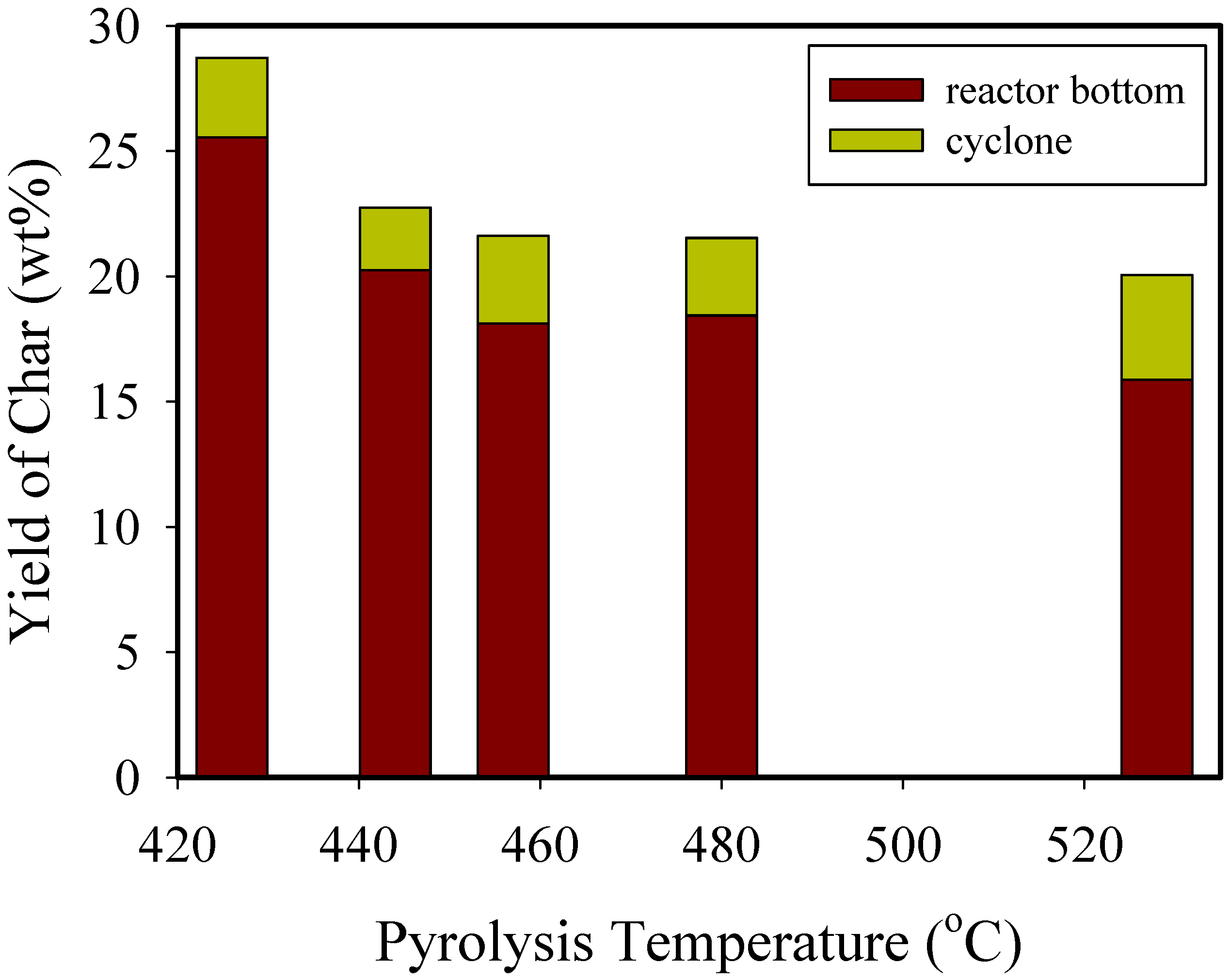
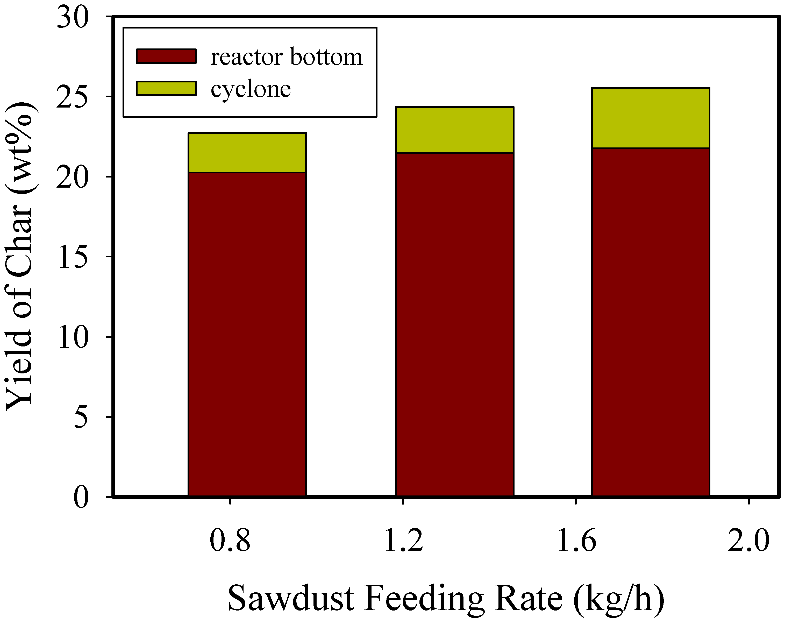
| 426 | 444 | 457 | 480 | 528 | 0.84 | 1.32 | 1.77 | |
| Yield (wt%) | 28.7 | 22.7 | 21.6 | 21.5 | 20.10 | 22.7 | 24.4 | 25.54 |
| Proximate anal. (wt%) | ||||||||
| Moisture content | 3.5 | 3.2 | 3.3 | 3.4 | 3.3 | 3.2 | 2.9 | 3.1 |
| Volatile matter | 37.5 | 33.1 | 32.1 | 26.4 | 22.0 | 33.1 | 36.3 | 36.1 |
| Fixed carbon | 50.1 | 53.6 | 59.3 | 56.6 | 58.3 | 53.6 | 53.6 | 57.1 |
| Ash | 9.0 | 10.2 | 5.3 | 13.6 | 16.4 | 10.2 | 7.3 | 3.6 |
| Elemental comp. (wt%) | ||||||||
| C | 68.6 | 74.0 | 66.5 | 75.7 | 58.0 | 74.0 | 64.2 | 72.8 |
| H | 4.6 | 4.8 | 3.8 | 4.0 | 2.3 | 4.8 | 4.0 | 4.5 |
| N | 0.4 | 0.3 | 0.3 | 0.4 | 0.6 | 0.3 | 0.4 | 0.4 |
| O a | 26.4 | 20.9 | 29.4 | 19.9 | 39.1 | 20.9 | 31.4 | 22.3 |
| O/C (mol/mol) | 0.38 | 0.21 | 0.33 | 0.20 | 0.51 | 0.21 | 0.37 | 0.23 |
| H/C (mol/mol) | 0.80 | 0.78 | 0.69 | 0.63 | 0.48 | 0.78 | 0.75 | 0.74 |
| HHV (MJ/kg) | 25.33 | 26.62 | 26.08 | 26.71 | 24.32 | 26.62 | 24.40 | 25.87 |
| Biochar Product | Proximate Analysis (wt%) | Ultimate Analysis b (wt%) | Heating Value c (MJ/kg) | ||||||||
|---|---|---|---|---|---|---|---|---|---|---|---|
| M a | VM | FC | Ash | C | H | N | S | O d | HHV | LHV | |
| Reactor bottom | 2.9 | 36.0 | 58.2 | 2.9 | 74.7 | 4.6 | 0.4 | ND e | 20.3 | 26.6 | 25.5 |
| Cyclone | 8.9 | 42.3 | 47.1 | 1.7 | 68.8 | 4.3 | 0.5 | 10−3 | 26.4 | 24.9 | 23.7 |
Publisher’s Note: MDPI stays neutral with regard to jurisdictional claims in published maps and institutional affiliations. |
© 2020 by the authors. Licensee MDPI, Basel, Switzerland. This article is an open access article distributed under the terms and conditions of the Creative Commons Attribution (CC BY) license (http://creativecommons.org/licenses/by/4.0/).
Share and Cite
Ha, J.H.; Lee, I.-G. Study of a Method to Effectively Remove Char Byproduct Generated from Fast Pyrolysis of Lignocellulosic Biomass in a Bubbling Fluidized Bed Reactor. Processes 2020, 8, 1407. https://doi.org/10.3390/pr8111407
Ha JH, Lee I-G. Study of a Method to Effectively Remove Char Byproduct Generated from Fast Pyrolysis of Lignocellulosic Biomass in a Bubbling Fluidized Bed Reactor. Processes. 2020; 8(11):1407. https://doi.org/10.3390/pr8111407
Chicago/Turabian StyleHa, Jong Hyeon, and In-Gu Lee. 2020. "Study of a Method to Effectively Remove Char Byproduct Generated from Fast Pyrolysis of Lignocellulosic Biomass in a Bubbling Fluidized Bed Reactor" Processes 8, no. 11: 1407. https://doi.org/10.3390/pr8111407
APA StyleHa, J. H., & Lee, I.-G. (2020). Study of a Method to Effectively Remove Char Byproduct Generated from Fast Pyrolysis of Lignocellulosic Biomass in a Bubbling Fluidized Bed Reactor. Processes, 8(11), 1407. https://doi.org/10.3390/pr8111407