Abstract
(1) Background: shape, dimension, hemodynamics, and hemocompatibility are just a few of the several challenging key points that must be addressed in designing any suitable solution for the ventricular chamber of mechanical circulatory support devices. A preliminary evaluation of different geometries of bellow-like ventricular chambers is herein proposed. The chambers were made with a polycarbonate urethane that is acknowledged to be a hemocompatible polymer. (2) Methods: an explicit dynamic computational analysis was performed. The actuation of the three chambers was simulated without the presence of an internal fluid. Maximum stress and strain values were identified, as well as the most critical regions. Geometric changes were checked during simulated motion to verify that the dimensional constraints were satisfied. (3) Results: one chamber appeared to be the best solution compared to the others, since its dimensional variations were negligible, and effective stresses and strains did not reach critical values. (4) Conclusions: the identification of the best geometric solution will allow proceeding with further experimental studies. Fluid–structure interactions and fatigue analyses were investigated.
1. Introduction
Today, research teams worldwide are engaged in the creation of a variety of innovative biomedical devices, such as the total artificial heart (TAH). Early development of TAHs is usually dated to the beginning of the 21st century when Charles Lindbergh and Alexis Carrel joined forces to advance mechanical circulatory supports []. After a sequence of trials in pre-clinical models, the first TAH implantation in a human was performed in 1969 as a bridge to cardiac transplantation []. More than fifty years later, only two devices have been approved for human use: the AbioCor Implantable Replacement Heart (IRH, Abiomed, Inc., Danvers, MA, USA) and the SynCardia Temporary Total Artificial Heart (TAH-t, SynCardia Systems, Inc., Tucson, AZ, USA) []. A third TAH has recently entered clinical trials: the CARMAT TAH, which has been implanted in patients at imminent risk of death (compassionate use) from biventricular heart failure, and who are not eligible for transplant [].
Nowadays, TAHs represent a bridge to transplant (BTT) solution, giving a significant survival chance to patients waiting for organ transplantation []. The implantation of these devices is increasingly important, but several drawbacks still limit their wider exploitation. First, the dimensions of the currently approved TAHs are relevant: they can only be implanted in patients with a body surface area (BSA) of 1.7–2.5 m2 or with a body mass between 84 and 129 kg [,]. However, the recently designed SynCardia 50 cc TAH has been approved for use in patients of smaller stature, allowing more women and adolescents to access this device.
The chest size is of paramount importance: 100 mm between the sternum and spinal vertebras is the minimum distance allowed, since a smaller size causes the device to compress important vessels (e.g., inferior vena cava and pulmonary veins) [].
Each TAH has to assure a blood flow rate ranging from 5 to 9 L/min. Most of the devices are operated by volumetric pumps, which are actuated by flexible membranes that allow the fluid to circulate by alternately expanding and reducing the inner volume of rigid domes. Thus, the imposed flow rate helps to determine the minimum size of the device. Indeed, researchers are evaluating the use of rotary pumps as non-pulsatile blood flow generators: they can sustain life with a non-physiological blood flow []. This might result in a reduction of the overall TAH dimensions.
During recent decades, different ventricular chambers have been designed to minimize the size and reduce the adverse reactions and complications caused by mechanical devices in permanent contact with the blood, in particular TAHs [], such as hemorrhages and thromboembolic events [].
The search for suitable and biocompatible biomaterials is still ongoing, but thermoplastic polyurethane elastomers are providing an important contribution to the development of blood-contacting components. These polymers assure good biocompatibility, hemocompatibility, and biostability; their physical and chemical properties are strictly related to the starting monomers. Polycarbonate-based polyurethanes (PCUs) achieve higher chemical and thermal stability compared to other polyurethanes. The relative amount of diisocyanate, chain extenders, and long-chain diol molecules determines the extension of soft and hard segments and the number of virtual crosslinks. Hence, it is possible to prepare a PCU characterized by tunable stiffness whose chemical and light resistance depends on the nature of its monomers [,].
A commercial PCU (ChronoFlex AR-LT, AdvanceSource Biomaterials, Wilmington, MA, USA) was identified for the production of an innovative prototype of a pulsatile ventricular chamber. It is composed of aromatic diisocyanates, such as methylene diisocyanate (MDI), polycarbonate diols, 1,3 diaminocyclohexane, and ethylene diamine (EDA), and it is characterized by the addition of silica microparticles to obtain low-tackiness features [,].
The present work is aimed at comparing three alternative geometries for a polymeric innovative ventricular chamber: whose development stems from the design patented by Gerosa et al. [], which identified an original configuration for the ventricular chamber of a novel TAH. The device is intended to be electro-magnetically actuated.
Preliminary computational analyses were carried out to verify that the geometrical constraints were constantly respected during actuation, and to find critical states in terms of stresses or strains; as these can cause the premature failure of the device.
Computational analyses were useful to select the most suitable design for the creation of a physical prototype.
2. Materials and Methods
2.1. Ventricular Chamber Configurations
Three alternative configurations for a bellow-like ventricular chamber were examined in the present work. 3D models were created using Autodesk Fusion 360® (Autodesk Inc., San Rafael, CA, USA). A wall thickness of 2 mm was considered. An overall volume not exceeding 100 mm in length, 80 mm in width, and 80 mm in height was imposed.
The investigated configurations of the ventricular chamber differ from each other as to the overall geometry and internal volume. The first model (Figure 1A) has a capacity of 60 mL, whereas the second (Figure 1B) and third (Figure 1C) models both have a capacity of 70 mL.
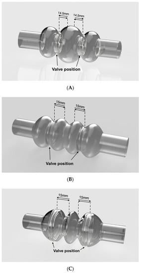
Figure 1.
Simulated ventricular chambers: (A–C) reproduce the geometric models of the three simulated configurations. Arrows indicate the displacement of the rigid plates (Model A and Model B) or the valve positions (Model C). Valve displacement is set at 14.5 mm for Model A, and 15 mm for Model B and Model C.
All configurations are characterized by the presence of three compartments; one central and two lateral. The central compartment is separated from the lateral ones by means of two prosthetic heart valves that assure unidirectional flow. The actuation of the device operates the valvular planes, moving them forward and backward; by alternate compression and expansion of the central compartment, the device receives and ejects blood. All compartments are flexible and the lateral ones are fixed at the edges, where they are to be connected to the patient’s atrium and aorta (or pulmonic artery), respectively; they have to follow the cyclic compression/expansion of the central compartment (Figure 2). The actuation will be performed by two rigid plates anchored to the valvular planes; the plates will be electromechanically moved by an external stator.
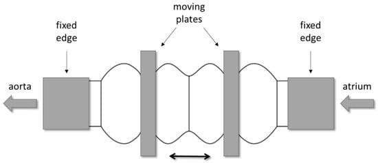
Figure 2.
Example of the mechanism for the actuation of the ventricular chamber: two rigid plates, anchored to the valvular planes, are electro-mechanically operated to compress and expand the central compartment.
The first configuration (Model A in Figure 1A) was equipped with two 21 mm heart valves located inside the necks between central and lateral compartments. The second configuration (model B in Figure 1B) contained two 31 mm valves, while the third (Model C in Figure 1C) was equipped with two 50 mm valves. The latter are not commercially available; thus, they had to be created specifically for this configuration. This configuration was conceived to avoid the presence of rigid valvular planes: valves should be sufficient to efficiently compress the rib of the central compartment.
The models were developed paying attention not to exceed the imposed size limits previously explained. The dimensions of the considered ventricular chambers are reported in Figure 3.
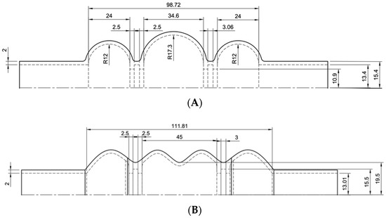
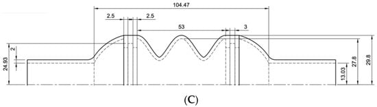
Figure 3.
Drawings of the three ventricular chambers. Sketches (A–C) provide the dimensions of the chambers.
2.2. PCU Characterization
Mechanical characterization of the ChronoFlex AR-LT was necessary to correctly simulate the material behavior during the computational analyses. Data were elaborated to obtain the stress vs. strain curve, which had to be implemented in simulation software (LS-DYNA).
Dog-bone-shaped samples of ChronoFlex AR-LT were used for uniaxial tensile tests (Figure 4). Tests were performed using a Bose ElectroForce Test Bench (TA Instruments, New Castel, DE, USA). Engineering stress σ (MPa) was calculated as the tensile force measured by the cell (Newton) divided by the original cross-sectional area measured in the middle of the sample; the strain ε (%) was defined as the ratio between the grip displacement and the gauge length. An elongation rate of 1 mm/s was set.
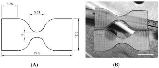
Figure 4.
Dog-bone-shaped samples: (A) dimensions and (B) aspects of the tested specimens (scale bar = 10 mm).
2.3. Computational Analyses
Computational analyses allowed the simulation of the dynamic behavior of the investigated ventricular chambers during actuation, that is, imposing cyclic expansion and compression of the compartments by moving the rigid plates back and forth. Given the mechanical properties of the material and the displacement of the rigid plates, it was possible to calculate the states of stress caused by the actuation. It is worth mentioning that the simulations were performed neglecting fluid–structure interactions.
Analyses were performed using the multiphysics solver LS-DYNA. The geometric model of each ventricular chamber was uploaded in LS Pre-Post; therefore, a mesh with shell elements was created for the flexible material (PCU), while solid elements were used for the plates (idealized as rigid bodies).
The elastomer was simulated using a two-parametric model (MAT027 MOONEY-RIVLIN_RUBBER), which required the following data: Poisson’s ratio (0.218), material’s density (1200 kg/m3), and the force versus actual gauge length change. Instead of the experimental loading curve, the engineering stress versus engineering strain curve was defined, since it was possible to set the thickness, width, and gauge length equal to 1 [].
A MAT020 MAT_RIGID material model was used for the rigid plates, and aluminum data were defined in the model card: density (2700 kg/m3), Young’s Modulus (70 GPa), and Poisson’s ratio (0.3).
Contact definition was necessary to avoid any kind of element penetration or sliding. The following constraints were set:
- AUTOMATIC_SINGLE_SURFACE: this contact avoided the interpenetration of the shell elements;
- AUTOMATIC_SURFACE_TO_SURFACE: this contact was defined to eliminate the penetration of solid elements into the shell elements and vice versa;
- TIED_NODES_TO_SURFACE contact was defined, since the rigid plates must not slide with respect to the ventricular chamber; the rigid plates must be fixed at the valves’ locations.
Boundary constraints were also defined to avoid undesired movement of the chamber and valvular planes, and to better simulate real actuation. No translations or rotations were allowed to the nodes of the cylindrical extremities of the chamber, while the planes could move only along the axis of the chamber.
Expansion and contraction of the model were reproduced by the symmetric motion of the valvular planes: a displacement versus time curve was defined, considering 10 mm as the minimum permitted distance between the valves (Table 1). Since the third configuration did not have rigid plates, motion was prescribed to mesh nodes at the valve level (Figure 5).

Table 1.
Displacement (for a single plane) from the original position versus time. For Model B and Model C, 15 mm was set as the maximum displacement, because of the different geometrical characteristics. Thus, the chamber can complete three cycles per second, that is, 180 bmp.
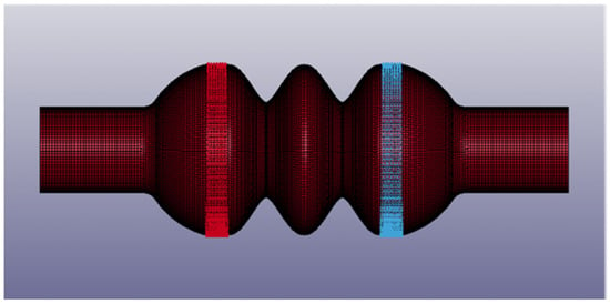
Figure 5.
Details of the third chamber configuration (Model C): moving nodes are in red and in blue. The image was captured from LS Pre-Post®.
It was supposed that the simulated ventricular chambers could not eject the whole fluid volume: for this reason, they were assumed to operate at about 180 bpm to assure the desired flow rate. This means that the rigid plates have to move back and forth at least 3 times per second. The behavior of the mechanical valves was simply simulated by an on/off mechanism, thus neglecting the opening/closing dynamics of the valve leaflets.
2.4. Mesh Convergence Analyses
Before reporting the results of the LS-DYNA® numerical simulations, a number of analyses were performed to validate the density of the adopted four-node shell element mesh (Figure 5). To accomplish this task, Ansys workbench® was adopted to rapidly import the geometry, generate the finite element (FE) mesh of a given size, and run the numerical analyses. A Mooney–Rivlin, 2 parameter, hyperelastic material was defined, and large displacement capability was activated in the simulation, so as to be consistent with the material and analysis settings adopted in the LS-DYNA® simulations, as discussed in Section 2.3. Model B was analyzed, and Figure 6 shows the different FE meshes adopted, while Table 2 specifies the mesh size corresponding to each FE model. More precisely, Table 2 indicates the size of the mesh generated in the fixed edges reported in Figure 1, where the radius of the cylindrical cross section is R. A constant displacement of 10 mm was imposed on to each moving plate. The Von Mises stress was evaluated on the outer point of the two central compartments, shown in Figure 1. Figure 7 reports the results versus the mesh density ratio R/a: it demonstrates that for R/a equal to or greater than 15 (translating into an element size a = 1 mm according to Table 2) convergence is practically achieved.
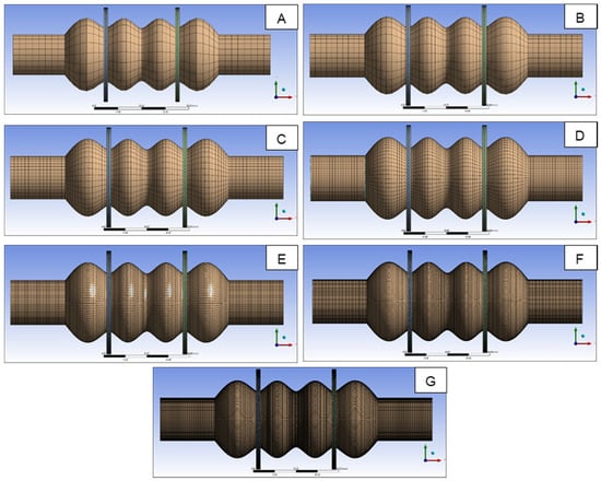
Figure 6.
FE models analyzed to validate the mesh size adopted in numerical simulations.
Table 2.
FE size of the different models reported in Figure 6.
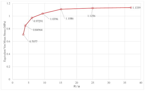
Figure 7.
Convergence of the Von Mises stress versus the mesh density ratio.
In the LS-DYNA® Simulations, a mapped mesh of 1-mm-shell elements was adopted, which is consistent with the convergence analysis reported in Figure 7. The results of the numerical simulations are reported and commented on in the next section.
3. Results
Figure 8 shows the engineering curve for the PCU, as obtained by the uniaxial tensile test. This curve was implemented in LS-DYNA® to simulate the mechanical behavior of the polymer. The experimental set up is shown in Figure 9.
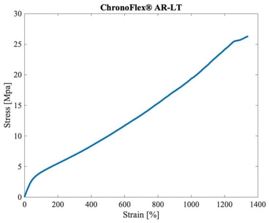
Figure 8.
Engineering curve of the ChronoFlex® AR-LT, as obtained by the uniaxial tensile tests.
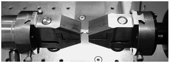
Figure 9.
Uniaxial test set up: the dog-bone-shaped sample was held by the two grips, and elongated by the electromagnetic actuators.
The first configuration of the ventricular chamber (Model A) generated a maximum stress lower than 1 MPa and a maximum strain of 18.3% (values are expressed as effective Von Mises stress and effective strain, respectively). These values were achieved at the maximum compression of the central compartment (Figure 10A). They were not excessive, but the central compartment diameter increased from 66 mm up to 80 mm. As shown in Figure 10B, the second configuration (Model B) reached the maximum stress in the middle of the central compartment (1.5 MPa). The maximum deformation was 19.5%, and the diameter did not change appreciably; it increased from 55 mm to 57 mm. The third configuration (Model C) showed an intensive deformation of the lateral compartments: at maximum compression, a stress of 3.5 MPa and a strain of 60% were developed in these regions (Figure 10C). As for Model B, the expansion of the central compartment was minimal, from 60 mm to 65 mm.
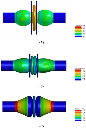
Figure 10.
Results of the numerical simulations: (A–C) illustrate Von Mises effective stress at the maximum compression of the three simulated ventricular chamber configurations.
Model B seemed to be the best compromise between the state of stress and the dimensional constraints. For this reason, the force vs. displacement curve was also acquired for Model B (Figure 11).
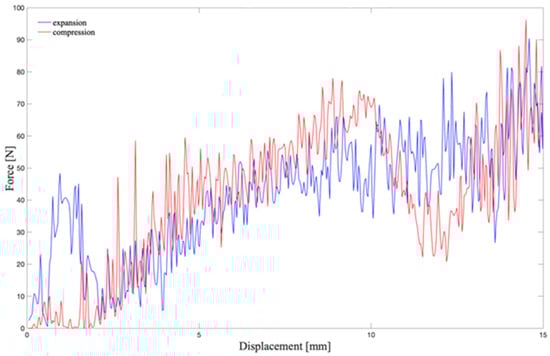
Figure 11.
Force vs. displacement curve: its integration gives the work that the plate has to develop to compress the chamber. The red line shows the calculated force during the compression of the chamber; the blue line represents the force during the expansion, from 15 mm to the initial position.
4. Discussion
In order to compare three different configurations of an innovative ventricular chamber, numerical simulations were performed without considering fluid–structure interactions. The first configuration (Model A) did not show excessive stresses nor deformations, but the radial expansion of the central compartment made it unsuitable for the intended application: the diameter increased up to 80 mm, thus exceeding the imposed geometric constraints. When the central compartment was fully compressed, Model B showed an almost negligible variation of its diameter, from 55 mm to 57 mm. In Model C, the central compartment diameter varied from 60 mm to 65 mm. Fulfilling the geometric constraints is mandatory for the intended application. The mechanical heart, which is composed of two independently operated ventricular chambers, has to be surgically placed within the recipient’s chest: therefore, it has to be small enough to suit a wide number of individuals, even pediatric patients and women.
Stress and strain values, as determined by numerical simulations, are important to compare the performance of the intended ventricular chambers. It is fundamental to assess the order of magnitude of the stresses and deformations caused by the motion of the chamber, as this information allows for the preliminary selection of the material suitable for the production of the physical prototype. Model A and Model B were characterized by low stress states compared to Model C; indeed, both models A and B reached a maximum stress lower than 2 MPa, and diameter deformations (estimated for the central compartment) of 18.3% and 19.5%, respectively. Model C showed an important elongation during the compression of the central compartment: a strain of 60% and a stress of 3.5 MPa were achieved.
The estimated stress and strain values allowed the exclusion of Model C. Moreover, the imposed dimensional constraints indicated that Model B was the most appropriate for the intended purpose. Thus, the force vs. displacement curve was calculated for Model B: it allowed the work that the actuation system has to perform to compress the chamber (without fluid) to be estimated. By trapezoidal numerical integration of the curve, the work required for moving one valvular plane is 1.21 J. Power was then calculated dividing the work by the time interval of the actuation, i.e., 300 ms. Theoretically, a power of 4.03 W is required for actuating one valvular plane. Since the chamber is supposed to be symmetrically operated by two moving planes, the total power needed is higher than 8 W.
There is at least one other fundamental aspect to consider in designing any blood-contact device, that is, its hemocompatibility []. It implies the absence of hemolysis and platelet activation, and the prevention of the cellular components’ consumption, and activation of coagulation pathways. In order to improve the blood compatibility of the proposed ventricular chamber, its inner surfaces will be produced with an innovative material obtained by coupling the aforementioned polymer with decellularized porcine pericardium. The synthetic polymer will give the chamber walls the necessary mechanical resistance, while the decellularized tissue will provide hemocompatibility.
5. Conclusions
The investigation of a novel TAH is an ambitious challenge: the present project, which includes the development of the innovative ventricular chamber, aims at overcoming the drawbacks and limitations of the existing devices. Recent scientific and technological achievements have allowed the production of more hemocompatible materials, and the design of less bulky devices, which can be implanted in smaller patients, i.e., women and adolescents []. Moreover, the intended electromechanical actuation, combined with the fully implantable battery, will make patients free from percutaneous drivelines and an external power supply. Taken together, all these features along with optimized hemodynamic performances will open the way towards the development of a reliable TAH, as the destination therapy. This can be a solution to face the growing shortage of organs from donors. The clinical and social impact of such an accomplishment can be easily understood, considering that heart failure is an ever-increasing problem: it affects millions of people worldwide and one out of five will develop heart failure in their lifetime []. Furthermore, 5% of these are “end-stage” patients, with terminal heart failure, and every 10 min, a new patient is included on the transplant waiting list [].
Starting from an original configuration of a pulsatile ventricular chamber, three different models were compared by numerical simulation. It is worth noting that the present analysis is of a preliminary nature. This work allowed selecting the most suitable configuration for the intended ventricular chamber, as well as guiding the selection of the material to be used for the production of the physical prototype.
The presence of a fluid and the pressure drop across the chamber will be taken into account during further simulations on the selected model prior to moving towards the creation of a physical prototype. The latter will be assessed experimentally to determine its performance.
Author Contributions
Conceptualization, G.M., A.F., G.G. and A.B.; methodology, V.C., M.T., G.M. and A.B.; software, G.M. and V.C.; validation, A.V., A.B. and G.M.; formal analysis, A.V., V.C. and M.T.; investigation, G.M. and V.C.; resources, G.M. and A.B.; data curation, A.V. and V.C.; writing—original draft preparation, V.C. and A.B.; writing—review and editing, G.M., A.F. and A.B.; visualization, V.C.; supervision, G.M. and A.B.; project administration, A.B.; funding acquisition, G.G. and A.B. All authors have read and agreed to the published version of the manuscript.
Funding
This work was supported by the LifeLab Program of the Consorzio per la Ricerca Sanitaria (CORIS) of the Veneto Region, Italy (DGR1017, 17 July 2018).
Conflicts of Interest
The authors declare no conflict of interest.
References
- Khan, S.; Jehangir, W. Evolution of Artificial Hearts: An Overview and History. Cardiol. Res. 2014, 5, 121–125. [Google Scholar] [CrossRef] [PubMed]
- Cooley, D.A.; Liotta, D.; Hallman, G.L.; Bloodwell, R.D.; Leachman, R.D.; Milam, J.D. Orthotopic cardiac prosthesis for two-staged cardiac replacement. Am. J. Cardiol. 1969, 24, 723–730. [Google Scholar] [CrossRef]
- Gaitan, B.D.; Thunberg, C.A.; Stansbury, L.G.; Jaroszewski, D.E.; Arabia, F.A.; Griffith, B.P.; Grigore, A.M. Development, current status, and anesthetic management of the implanted artificial heart. J. Cardiothorac. Vasc. Anesth. 2011, 25, 1179–1192. [Google Scholar] [CrossRef] [PubMed]
- Carpentier, A.; Latrémouille, C.; Cholley, B.; Smadja, D.M.; Roussel, J.C.; Boissier, E.; Trochu, J.N.; Gueffet, J.P.; Treillot, M.; Bizouarn, P.; et al. First clinical use of a bioprosthetic total artificial heart: Report of two cases. Lancet 2015, 386, 1556–1563. [Google Scholar] [CrossRef]
- Lee, T.; Torregrossa, G. Total artificial heart. In Encyclopedia of Cardiovascular Research and Medicine; Elsevier Inc.: Amsterdam, The Netherlands; Mount Sinai St. Luke’s Hospital: Amsterdam, NY, USA, 2018; pp. 545–557. [Google Scholar]
- Smith, P.A.; Cohn, W.E.; Frazier, O.H. Mechanical Circulatory and Respiratory Support; Gregory, S.D., Stevens, M.C., Fraser, J.F., Eds.; Academic Press: Cambridge, MA, USA, 2018; Volume 1, pp. 221–244. [Google Scholar]
- Dal Sasso, E.; Bagno, A.; Scuri, S.T.G.; Gerosa, G.; Iop, L. The Biocompatibility Challenges in the Total Artificial Heart Evolution. Annu. Rev. Biomed. Eng. 2019, 4, 85–110. [Google Scholar] [CrossRef] [PubMed]
- Reed, A.M.; Potter, J.; Szycher, M. A Solution Grade Biostable Plyurethane Elastomer: ChronoFlex® AR. J. Biomater. Appl. 1994, 8, 210–236. [Google Scholar] [CrossRef]
- Marcano, A.; Fatyeyeva, K.; Koun, M.; Dubuis, P.; Grimme, M.; Marais, S. Barrier behavior of biomedical polyurethanes: Relationship of structure, morphology and properties. Biointerface Res. Appl. Chem. 2018, 8, 3324–3334. [Google Scholar]
- Scuri, S.T.G.; Mantovani, F.; Perlato, T.; Gerosa, G.; Susin, F.M. Pumps having Flexible Elements, e.g., with Membranes, Diaphragms, or Bladder pumps. International Application Published Under the patent Cooperation Treaty (PCT). International Publication Number WO2015092732A1, 18 December 2014. [Google Scholar]
- LS-DYNA®. Keyword User’s Manual Volume II Material Models; Livermore software technology Corporation (LSTC): Troy, MI, USA, 2014. [Google Scholar]
- Gerosa, G.; Scuri, S.; Iopo, L.; Torregorssa, G. Present and future perspectives on total artificial hearts. Ann. Cardiothorac. Surg. 2014, 3, 595–602. [Google Scholar]
- Ensminger, S.; Morshuis, M.; Gummert, J. A Novel Bioprosthetic Total Artificial Heart. Transplantation 2016, 100, 699–700. [Google Scholar] [CrossRef] [PubMed]
- Sunjaya, A.F.; Sunjaya, A.P. Combating Donor Organ Shortage: Organ Care System Prolonging Organ Storage Time and Improving the Outcome of Heart Transplantations. Cardiovasc. Ther. 2019, 1, 9482797. [Google Scholar] [CrossRef] [PubMed]
Publisher’s Note: MDPI stays neutral with regard to jurisdictional claims in published maps and institutional affiliations. |
© 2020 by the authors. Licensee MDPI, Basel, Switzerland. This article is an open access article distributed under the terms and conditions of the Creative Commons Attribution (CC BY) license (http://creativecommons.org/licenses/by/4.0/).