Article

A Reference-Model-Based Artificial Neural Network Approach for a Temperature Control System

1
Division of Electronics and Informatics, Gunma University, Kiryu 376-8515, Japan
2
Department of Electrical Engineering, Yangzhou University N.196 Huayang West Road, Yangzhou 225-000, China
3
R & D Division, RKC Instrument Inc., Tokyo 146-8515, Japan
*
Author to whom correspondence should be addressed.
Current address: 1-5-1 Tenjin-cho, Kiryu, Gunma 376-8515, Japan.
These authors contributed equally to this work.
Processes 2020, 8(1), 50; https://doi.org/10.3390/pr8010050
Submission received: 31 October 2019 / Revised: 10 December 2019 / Accepted: 19 December 2019 / Published: 1 January 2020
(This article belongs to the Section Process Control and Monitoring)

Abstract

:
Artificial neural networks (ANNs), which have excellent self-learning performance, have been applied to various applications, such as target detection and industrial control. In this paper, a reference-model-based ANN controller with integral-proportional-derivative (I-PD) compensation has been proposed for temperature control systems. To improve the ANN self-learning efficiency, a reference model is introduced for providing the teaching signal for the ANN. System simulations were carried out in the MATLAB/SIMULINK environment and experiments were carried out on a digital-signal-processor (DSP)-based experimental platform. The simulation and experimental results were compared with those for a conventional I-PD control system. The effectiveness of the proposed method was verified.

1. Introduction

Industrial processes, such as thermal and manufacturing processes, are becoming increasingly important, and processing high requirements for operation performance. Heating systems are used in thermal processes, which have a wide range of industrial applications, especially in food processing. A variety of control methods have been proposed for the precise temperature control and improved the transient response of heating systems. Conventional control methods, especially proportional-integral-derivative (PID) control, have become commonly used due to their simplicity and applicability, even for multi-point temperature control systems [1,2,3,4,5].
However, due to the nonlinearity and large lag of heating systems, the performance of a PID control system may not meet the requirements. A series-connected fuzzy-proportional integral control method has been proposed to improve control performance [6]. In addition, to achieve more precise control, a mathematical model of the controlled object is required. Numerous identification methods have been used to build such models. One of the most popular methods is the step response method [7,8,9,10].
Based on the mathematical plant model, some advanced compensation method have been proposed to improve the performance of conventional PID control, including Smith estimator predictive control [11], self-adaption control [12], generalized predictive control [13], fuzzy control [14] and model predictive control [15].
For complex heating process systems, the mathematical model cannot be obtained precisely. Data-driven approaches have been proposed for controlling such systems [16], Some optimization methods have also been proposed [17].
A problem with typical heating system control methods is that once the parameters of the control system are defined, they cannot be adjusted while the system is in operation. Plant perturbations thus lead to instability of the control system. Artificial neural networks (ANNs), which have excellent self-learning ability and can adjust their parameters online to handle variations of the controlled system, have received increasing attention for industrial applications. With advancements in machine learning methods, ANNs has been applied to a number of industrial applications, such as the development of an occupancy prediction model [18], improvement of thermal comfort indices [19], and data measurement in temperature control systems [20,21,22,23,24]. For a thermal process system with strong nonlinearly, large lag and strong coupling, an adaptive system can improve control performance in terms of the transient response and overshoot [25,26,27].
In the present study, to improve the transient response of a heating system with strong nonlinearity and large lag, a reference-model-based ANN control method is proposed. In the proposed method, the system is driven by the error signal between the reference model output and the real system output. This error signal is used as the teaching signal for the ANN. The ANN controller is added to an I-PD control system to appropriately adjust the control input. The rest of the paper is organized as follows. The configuration of the proposed system is described in detail in Section 2. The simulation and experimental results for the proposed method are presented in Section 3 and Section 4, respectively. The results are compared with those for a conventional I-PD control system. The conclusions are given in Section 5.

2. Configuration of ANN with Reference Model System

In this section, we describe the configuration of the proposed ANN control system with a reference model. Figure 1 shows the block diagram of the reference-model-based ANN control system.
For simplicity, the controlled object is expressed as a first order plus time delay (FOPTD) model. In Figure 1, y r e f is the set reference value for the system, e y is the teaching signal for the ANN controller, which is calculated as the error between the output y r of reference model R m and the output temperature y, C is a conventional PID controller (in this paper, an I-PD configuration is employed), and x is the control input, which is the sum of the ANN controller output x N and IPD output x C . The reference model R m is designed based on the controlled object, thus it can provide the reference output temperature with the same time delay. The explanation of the control system is divided into four main parts.

2.1. Controlled Object with Time Delay

The controlled object is the thermal processing system, which can be represented as a FOPTD system. With its large delay time, the transfer function of the plant can be expressed as Equation (1), where K is the steady-state gain of the output temperature against the input signal, T is the time constant of the plant, and τ is the delay time of the response. The step response of the plant is shown in Figure 2. Since this model is only suitable to the autotuning method of the I-PD controller, it is not required to design the ANN controller itself.
P ( s ) = K T s + 1 e τ s

2.2. Conventional I-PD Control

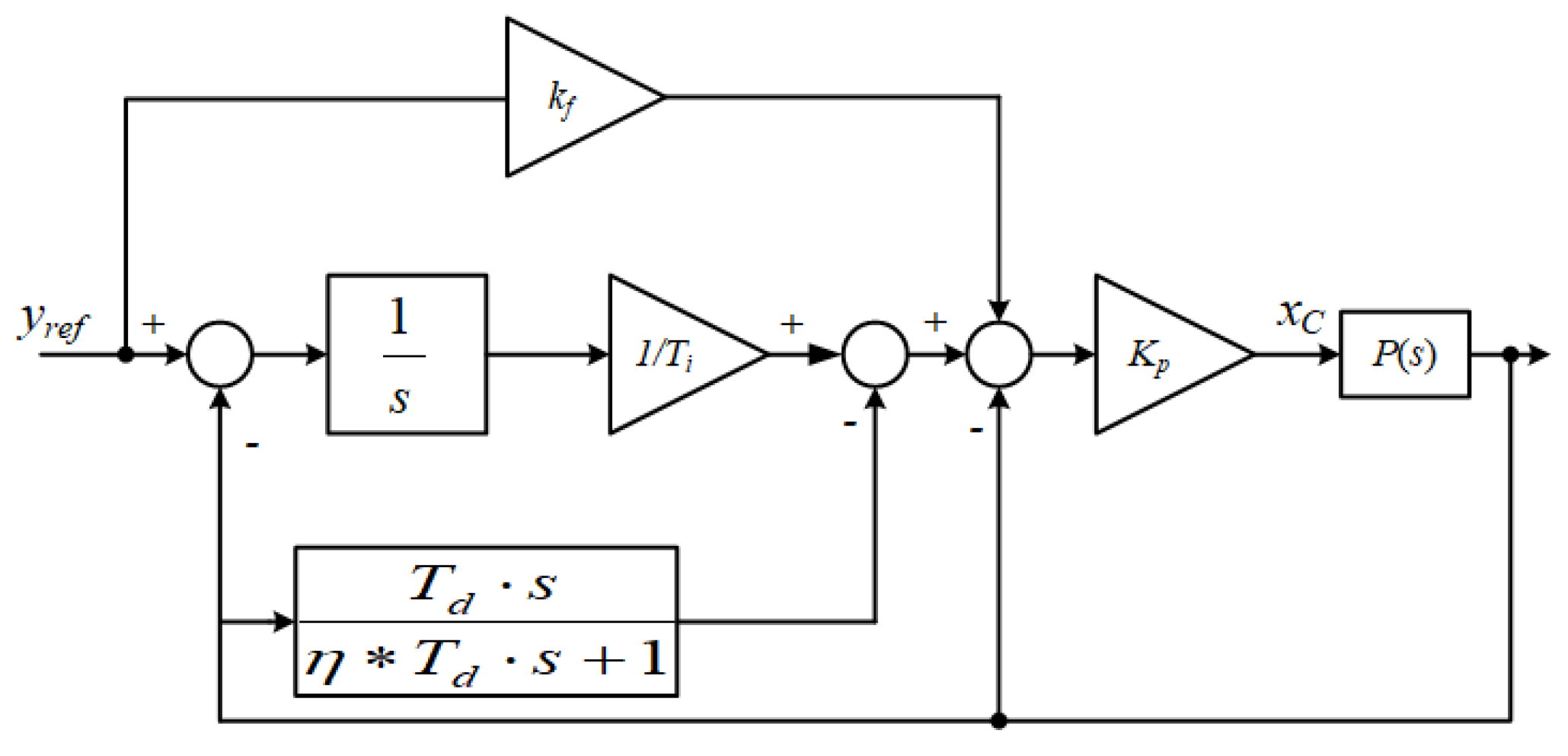
Considering that the ANN controller needs time to learn and train its parameters, and will mainly act after finishing training, a conventional I-PD controller is designed for the control of the initial state. The block diagram of I-PD controller is shown in Figure 3, where k f is the feed-forward gain used to decide the system response speed (0: slow; 0.5: middle; 1: fast), T i is the integral time constant, T d is the differential time constant, η is the gain of the low-pass filter (LPF) which is necessary for the feasibility of the derivative action, and K p is the proportional gain of the controller.
Stability is one of the most important factors of a controller. Several methods have been proposed for controller stability analysis [28,29]. Because the parameters of the I-PD controller are designed based on the Ziegler–Nichols rule (step response method), stability is ensured [30]. These values are determined by τ , K and T in Equation (1). The I-PD parameter K p , T i and T d can be calculated as Equations (2)–(4), respectively.
K p = 1.2 T τ
T i = 0.5 T
T d = 2 τ

2.3. ANN Controller

In order to realize model free control and auto learning for reference model output tracking, a multi-layer ANN controller is introduced into the I-PD control system. In the proposed system, the ANN controller has one input layer, two hidden layers, and one output layer. The two hidden layers have 10 neurons, and thus the structure of the ANN controller is 2-10-10-1.
In this system, the reference value of the system y r e f and the output temperature y are set as the input signals of the ANN. x N is the output value of the ANN. The calculation process, from the input N i n to the output N o u t , is shown in Equation (5), where N N i n is the input vector and N N o u t is the output vector, the W 1 , W 2 and W 3 are the weight of neurons, θ 1 and θ 2 are the offset value for each hidden neuron, and f(·) is the neuron activation function.
N N o u t = W 3 f ( W 2 f ( W 1 N N i n + θ 1 ) + θ 2 )
Regarding self-learning, the back-propagation algorithm is applied for the weight training and neuron bias update. Assuming that neuron j is a neuron in hidden layer connected to the output neuron k. The signal flow analysis is under the nth iteration (i.e., nth training sample). The neuron j is fed by a set of function signals produced by a layer of neurons to its left. Thus, the output of neuron j and k can be obtained as Equations (6) and (7), respectively, where m is the total number of inputs (excluding the bias) applied to neuron j (here, m = 10). The synaptic weight w j 0 (corresponding to the fixed input y 0 = +1) equals the bias θ j applied to neuron j.
y j ( n ) = f ( i = 0 m w j i ( n ) y i ( n ) )
y k ( n ) = f ( j = 1 m w k j ( n ) y j ( n ) )
The back-propagation begins at the output layer of the ANN controller. The error signal is used as the teaching signal for the neurons, the error signal at nth iteration is defined as Equation (8), which is provided by the difference between the reference model output y r e f and the real plant output y r , as is shown in Figure 1.
e k ( n ) = y r ( n ) y ( n )
According to the back-propagation algorithm, the corrections of the weight w k j is that in Equation (9) and Δ w k j is obtained as shown in Equation (10), where α is the learning gain, and ε(n) is the instantaneous value of the error energy.
w k j ( n + 1 ) = w k j ( n ) + Δ w k j ( n )
Δ w k j ( n ) = α ε ( n ) w k j ( n )
The weight correction for neuron j is obtained as shown in Equation (11). Δ w j i ( n ) is expressed as shown in Equation (12), where δ j ( n ) is the local gradient of neuron j, and can be calculated as shown in Equation (13), m k is the total number of output layer (here, m k = 1).
w j i ( n + 1 ) = w j i ( n ) + Δ w j i ( n )
Δ w k j ( n ) = α ε ( n ) w k j ( n ) = α δ j ( n ) y i ( n )
δ j ( n ) = f ( v j ( n ) ) k = 1 m k δ k ( n ) w k j ( n )
The neuron bias needs to be adjusted. The correction is determined by δ(n). The bias correction for neuron j at the nth iteration is expressed as Equation (14), where β is the bias training gain.
θ j ( n + 1 ) = θ j ( n ) β δ j ( n )
To improve the self-learning ability of the ANN controller, the ReLu neuron activation function, shown in Equation (15) has been applied, and its derivative is shown in Equation (16).
f ( x ) = x , x > 0 0 , x 0
f ( x ) = 1 , x > 0 0 , x 0

2.4. Reference Model-Based ANN Control System

The reference model, which is based on the plant transfer function, is applied to provide the training signal for the ANN controller and also help to prevent the over learning of the NN controller. Reducing the memory required to store the output can make the controller realization easy, thus the approximation of the dead time needs to be introduced. There are several approximation methods, such as graphical approximation and Pad e ´ approximation. Here, the Pad e ´ approximation method is applied, as given by Equation (17).
e τ s 1 ( τ s 2 + 1 ) 2
The reference model settings are based on the approximated plant model. To improve the transient response speed, gain R is added to the plant time constant in the approximated model as shown in Equation (18).
R ( s ) K T R s + 1 × 1 ( τ s 2 + 1 ) 2

3. Simulation Results

3.1. Comparison Simulation with Conventional Error Feedback ANN Method

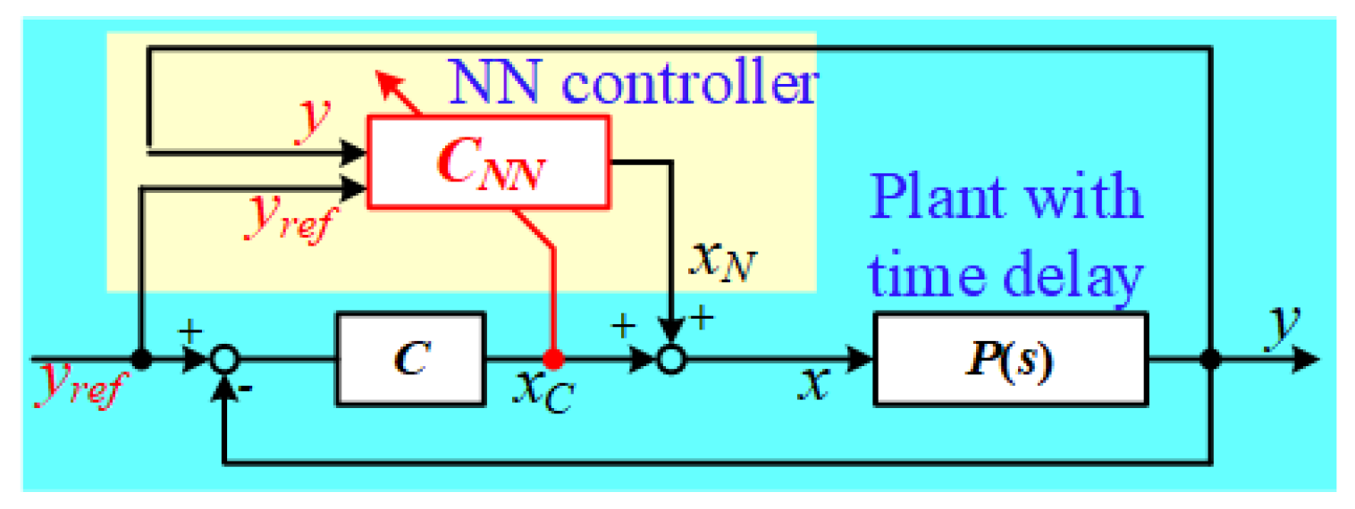
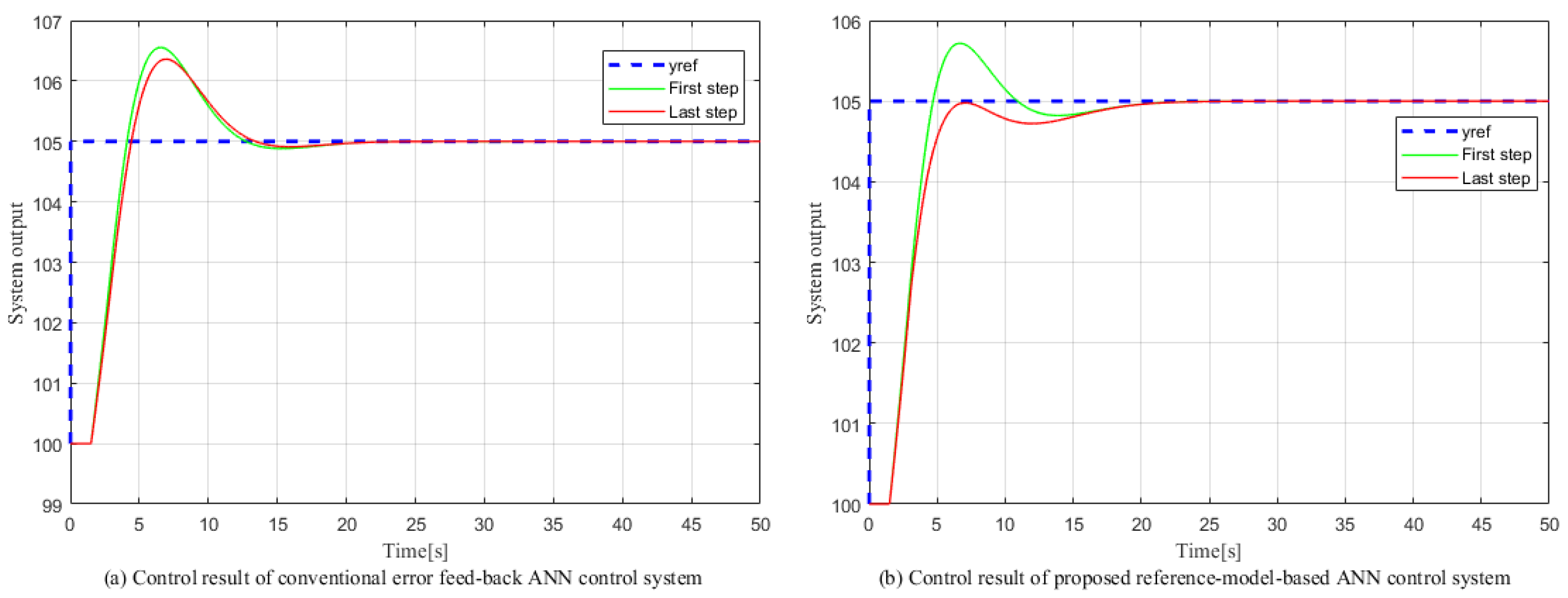
To verify the proposed control method, the comparison with conventional error feedback ANN control method needs to be carried out. The structure of the conventional error feedback ANN control method is shown in Figure 4, where the output of the IPD controller is used as the learning signal of the NN controller. In this comparison simulation, the control object is freely chosen as Equation (19), which only has 1 s delay time, and the reference model is designed as introduced above. Both the conventional error feedback ANN control method and the proposed reference-model-based ANN control method has been applied to this control object, a step signal from 100 to 105 is applied as the reference value which will be repeated several times, and have both first step response and the last step response compared.
P ( s ) = 540 225 s + 1 e s
Figure 5a,b respectively show the time response of the conventional error feedback ANN control system and the proposed reference-model-based ANN control system. From the simulation results, the first step response and the last step response of the conventional error feedback ANN control are almost the same, which means that after repeating several times the conventional feedback ANN control merthod can’t improve the system response. However, by introducing the proposed reference-model-based ANN method, compared with the first step response the last step response has been improved by the overshoot and transient response. Thus, we state that our proposed reference-model-based ANN control method is better than the conventional error feedback ANN method.

3.2. Experimental Setup and System Identification

To verify the control efficiency of the reference-model-based ANN control method, the controlled object was based on a real plant system. A step response experiment was performed to obtain the transfer function for the controlled object. The experimental setup is shown in Figure 6. It includes a digital signal processor (DSP) as the temperature controller. The system has four coupled channels. Each channel has two independent heaters and one temperature sensor. The temperature sensor transforms the temperature (0–400 ° C ) into an output voltage (0–10 VDC). The heaters are controlled by the solid-state relay (SSR has shown in Figure 6), and the SSR is driven by pulse width modulation (PWM) signals. The temperature can be controlled through the duty ratio of the PWM signals.
Channel Ch1 is defined as the input channel (heating channel) and Ch4 is defined as the output channel. The step response method was used for system identification. The plant was identified as shown in Equation (20).
P ( s ) = 2.36 2626 s + 1 e 524 s

3.3. Simulation Results

The simulation was carried out in the MATLAB/SIMULINK environment. In the simulation, the controlled object was based on the identified plant (Equation (20)). Hence, the reference model was expressed as Equation (21). Here, R was set to 0.01.
R ( s ) 2.36 26.26 s + 1 × 1 ( 524 2 s + 1 ) 2
The I-PD parameters were determined by the plant parameters using the Ziegler–Nichols method, as described above. The parameters were K p = 10.3, T i = 838, and T d = 209. Moreover, the hyper-parameters of the ANN were determined as α = 1 × 10 9 and β = 2 × 10 5 , these two parameters are designed by try and error method. The initial value of the weight was set to a random value between −1 and 1.
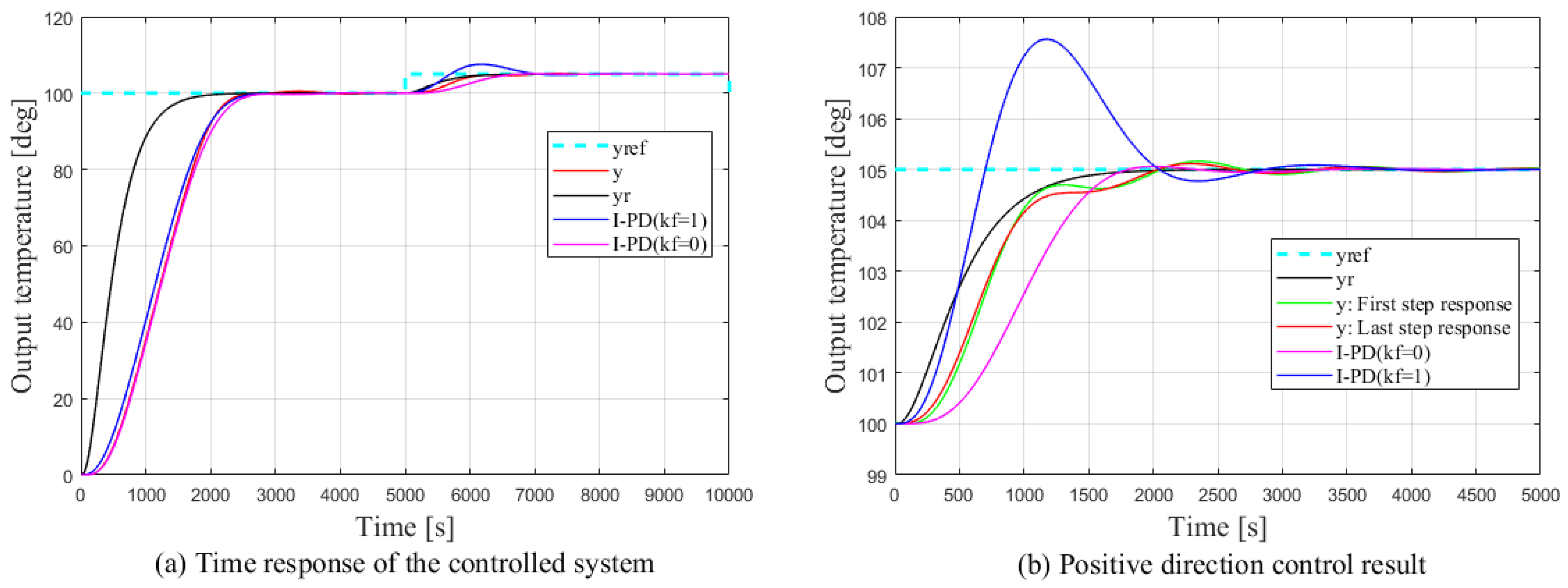
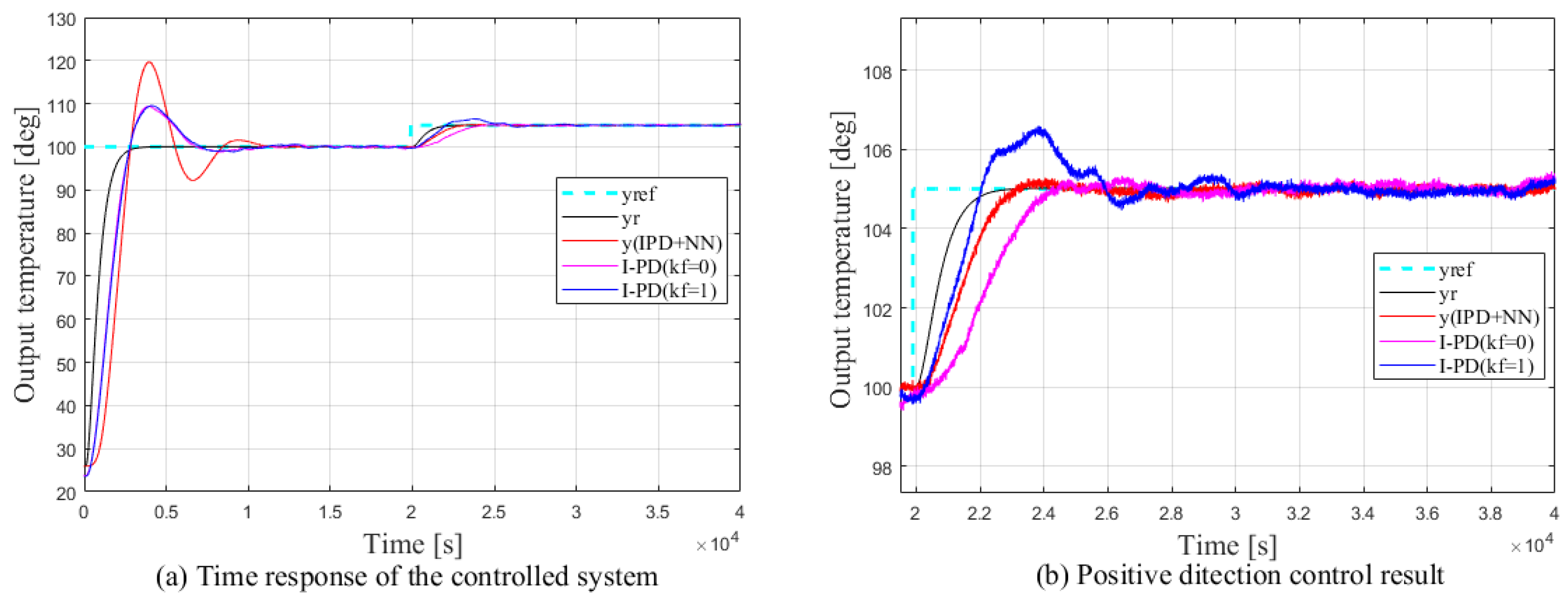
The simulation can be divided into two steps, namely the ANN learning period and positive direction control (we define control temperature from 100 ° C to 105 ° C as the positive direction control). In the first step, the temperature goes from 0 ° C to 100 ° C, and the control switches from I-PD controller to the ANN controller. In the second step, the reference is set to 105 ° C, and the temperature is controlled from 100 ° C to 105 ° C. This particular step will be repeated several times to obtain the first step and last step results. Figure 7a,b respectively show the time response of the controlled system and the results of the control system for temperature increase from 100 ° C to 105 ° C. The results were compared with those obtained using a conventional I-PD control system with feed-forward gain k f = 0 (slow) and k f = 1 (fast).
From the simulation results, the response time for the conventional I-PD control system is about 1300 s and that for the proposed ANN control system is about 700 s, an improvement of almost 46%. Moreover, because the first step response is almost the same as the last step response, the learning process ended at the beginning of the first step. The system response follows the reference model, although there is a slight deviation. These results show that the proposed system improved control efficiency. And from the simulation results, the last step response are almost the same, meaning the learning of the NN control was nearly finished by the time of the first step response, thus realizing the quick-learning.
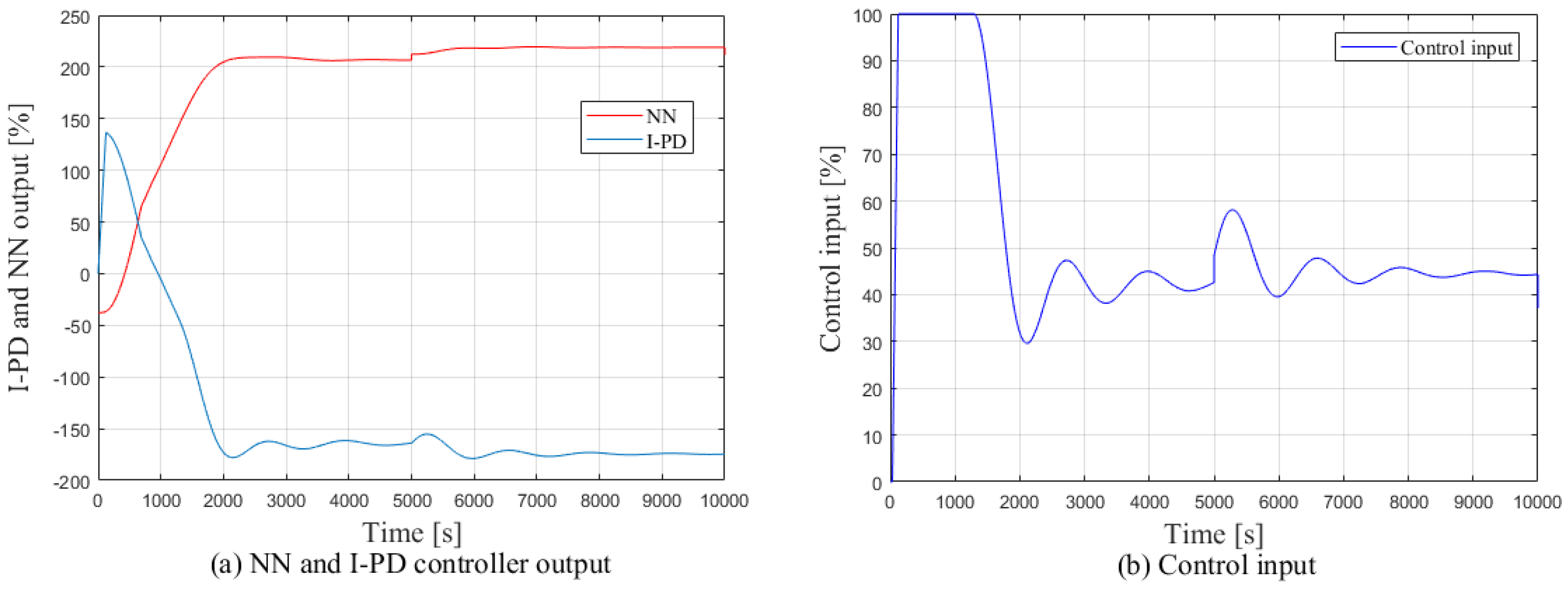
Figure 8a,b, respectively, show the outputs of the ANN and I-PD controllers and the control input, which is expressed as the sum of the ANN and I-PD outputs. As shown, the output of the I-PD controller is initially positive, about 140%, and that of the ANN controller is initially negative, about −40%. In this condition, the I-PD controller plays a dominant role. As the system approaches the setpoint, the output of the I-PD controller becomes negative, about −180%, and that of the ANN controller becomes positive, about 225%. The control efficiency switches from the I-PD controller to the ANN controller. The control input respects the sum of the I-PD and ANN output; the steady-state value is about 45%.

4. Experimental Results

Experiments with the proposed reference-model-based ANN control method were carried out using parameter values identical to those used in the simulation. The experimental setup was the same as that shown in Figure 6. The condition of experiments are as the following: sampling period is 0.1 s, controller sampling bit is 12 bits, sensor resolution is 0.1 ° C and the air conditioner is set as 25 ° C. In the experiments, as in the simulation, to verify the control efficiency of the proposed method, the results were compared with those for a conventional I-PD control system with feed-forward gain k f = 0 (slow) and k f = 1 (fast). The experiments were carried out by controlling the temperature of Ch1 from 100 ° C to 105 ° C. The results for the output temperature are shown in Figure 9. The temperature change from room temperature to 100 ° C is defined as the learning period of the ANN controller, and the temperature change from 100 ° C to 105 ° C is the control result for the controlled system.
The response time of the controlled system is about 2300 s and about 1900 s for the conventional I-PD system with k f = 0 and k f = 1, respectively, and about 2000 s for the proposed ANN control system. Although the response time for the proposed system is 5% slower than that for the I-PD ( k f = 1 ) system, it is 15% faster than that for the I-PD ( k f = 0 ) system. Although the I-PD ( k f = 1 ) system has the fastest response, it exhibits an overshoot of 1.5 ° C, which is about 30% of the reference value. The proposed ANN control system and the I-PD ( k f = 0 ) system do not exhibit overshoot. Thus, control effectiveness is improved by the proposed method. The simulation and experimental results both verigy the proposed reference-model-based ANN control method.
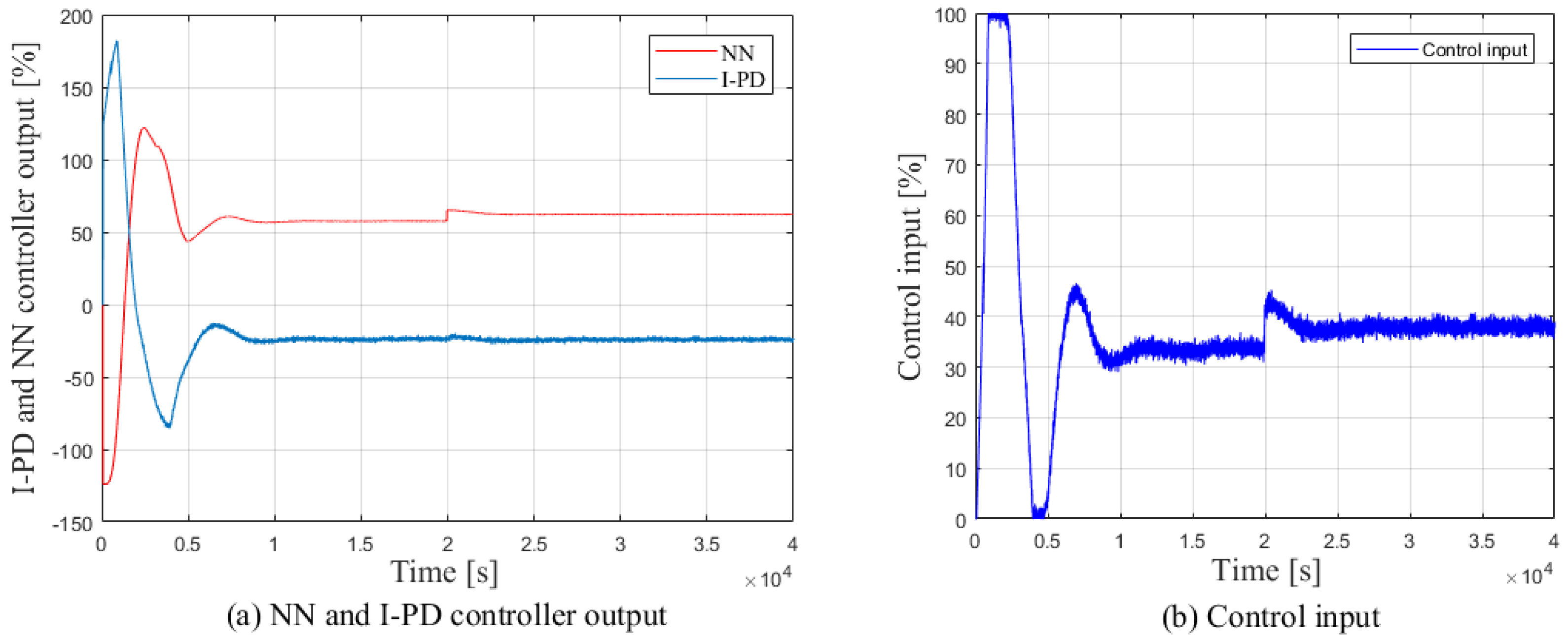
Figure 10a,b respectively show the output of the ANN and I-PD controllers and the control input, which is expressed as the sum of the ANN and I-PD output. As shown, the output of the I-PD controller is initially positive, about 140%, and that of the ANN controller is initially negative, about −120%. Under this condition, the I-PD controller plays a dominant role. As the system approaches the setpoint, the output of the I-PD controller becomes negative, about −25%, and that of the ANN controller becomes positive, about 63%. The control efficiency switches from the I-PD controller to the ANN controller. And the control input respects the sum of the I-PD output and ANN output; the steady-state value is about 38%.

5. Conclusions

In this paper, a reference-model-based ANN control method is proposed for temperature control systems. The error between the real system output and the reference model output is used to drive the system and this error signal is used as the teaching signal for the ANN controller. The whole control system is a combination of the ANN controller and the I-PD controller. The simulation was carried out in the MATLAB/SIMULINK environment to verify the control system. Experiments were carried out on a DSP based temperature system platform. Both simulation and experimental results were quantitively compared with those of the conventional I-PD control system to evaluate the improvement in the transient response. The control effectiveness of the proposed method was successfully verified. Although the transient response time and overshoot have been improved by the proposed ANN control method, there still remain some shortcomings such as the necessesity for the reference model to be based on the plant model, and presently the proposed method is only applied to the FOPTD plant.

Author Contributions

Conceptualization, S.H. and S.X.; methodology, S.H.; software, S.X. and Y.J.; validation, S.X., S.H., Y.J. and W.J.; formal analysis, S.H. and S.X.; investigation, S.H.; resources, W.J.; data curation, S.X. and Y.J.; writing—original draft preparation, S.X.; writing—review and editing, S.H.; visualization, W.J.; supervision, W.J.; project administration, S.H., K.I., T.K. and R.I.; funding acquisition, S.H., K.I., T.K., R.I. and W.J. All authors have read and agreed to the published version of the manuscript.

Funding

This research received no external funding.

Acknowledgments

In this section you can acknowledge any support given which is not covered by the author contribution or funding sections. This may include administrative and technical support, or donations in kind (e.g., materials used for experiments).

Conflicts of Interest

The authors declare no conflict of interest.

References

  1. Suda, N. PID Control; Asakura Publishing: Tokyo, Japan, 1992. [Google Scholar]
  2. Oshima, M. Process Control Systems; Corona Publishing: New York, NY, USA, 2003. [Google Scholar]
  3. Goodwin, G.C.; Fraebe, S.F.; Salgado, M.E. Control System Design; Prentice Hall: Upper Saddle River, NJ, USA, 2001. [Google Scholar]
  4. Morari, M.; Zafiriou, E. Robust Process Control; Prentice Hall: Upper Saddle River, NJ, USA, 1992. [Google Scholar]
  5. Maciejowski, J.M. Multivariable Feedback Design; Addison Wesley: Boston, MA, USA, 1989. [Google Scholar]
  6. Ko, J.S.; Huh, J.H.; Kim, J.C. Improvement of Temperature Control Performance of Thermoelectric Dehumidifier Used Industry 4.0 by the SF-PI Controller. Processes 2019, 7, 98. [Google Scholar] [CrossRef] [Green Version]
  7. Song, B.Q.; Mills, J.K.; Liu, Y.H.; Fan, C.Z. Nonlinear Dynamic Modeling and Control of a Small-Scale Helicopter. Int. J. Control Automat. Syst. 2010, 8, 534–543. [Google Scholar] [CrossRef]
  8. Fujimori, A.; Ohara, S. Order Reduction of Plant and Controller in Closed Loop Identification based on Joint Input-Output Approach. Int. J. Control Automat. Syst. 2017, 15, 1217–1226. [Google Scholar] [CrossRef]
  9. Yao, Y.; Yang, K.; Huang, M.; Wang, L. A state-space model for dynamic response of indoor air temperature and humidity. Build. Environ. 2013, 64, 26–37. [Google Scholar] [CrossRef]
  10. Yao, Y.; Yang, K.; Huang, M.; Wang, L. A technique for identification of linear systems. IEEE Trans. Autom. Control 1965, AC-10, 461–464. [Google Scholar]
  11. Fliess, M.; Marquez, R.; Mounier, H. An extension of predictive control: PID regulators and Smith predictors to some linear delay systems. Int. J. Control 2002, 75, 728–743. [Google Scholar] [CrossRef]
  12. Bai, J.; Wang, S.; Zhang, X. Development of an adaptive Smith predictor-basedself-tuning PI controller for an HVAC system in an experiment room. Energy Build. 2008, 40, 2244–2252. [Google Scholar] [CrossRef]
  13. Xu, M.; Li, S. Practical generalized predictive control with decentralized identification approach to HVAC systems. Energy Convers. Manag. 2007, 48, 292–299. [Google Scholar] [CrossRef]
  14. Zhang, J. Experimental study on a novel fuzzy control method for static pressure reset based on the maximum damper position feedback. Energy Build. 2015, 108, 215–222. [Google Scholar] [CrossRef]
  15. Afram, A.; Janabi-Sharifi, F. Theory and applications of HVAC control systems—Areview of model predictive control (MPC). Build. Environ. 2014, 72, 343–355. [Google Scholar] [CrossRef]
  16. Gao, Z.; Nguang, S.K.; Kong, D.X. Data-driven approaches for complex industrial systems. IEEE Trans. Ind. Inform. 2013, 9, 2210–2212. [Google Scholar] [CrossRef]
  17. Gao, Z.; Nguang, S.K.; Kong, D.X. Advances in Modelling, Monitoring, and Control for Complex Industrial Systems. Complexity 2019, 2019, 2975083. [Google Scholar] [CrossRef]
  18. Ryu, S.H.; Moon, H.J. Development of an occupancy prediction model using indoor environmental data based on machine learning techniques. Build. Environ. 2016, 107, 1–9. [Google Scholar] [CrossRef]
  19. Megri, A.C.; Naqa, I.E. Prediction of the thermal comfort indices using improved support vector machine classifiers and nonlinear kernel functions. Indoor Built Environ. 2016, 25, 6–16. [Google Scholar] [CrossRef] [Green Version]
  20. Badia, M.; McCarthy, R. Data estimation methods for predicting temperatures of fruit in refrigerated containers. Biosyst. Eng. 2016, 151, 251–272. [Google Scholar]
  21. Mercier, S.; Marcos, B. Identification of the best temperature measurement position inside a food pallet for the prediction of its temperature distribution. Int. J. Refrig. 2017, 76, 147–159. [Google Scholar] [CrossRef]
  22. Badia, M.; Qian, J.P.; Fan, B.L. Artificial neural networks and thermal image for temperature prediction in apples. Food Bioprocess Technol. 2012, 9, 1089–1099. [Google Scholar] [CrossRef]
  23. Nunes, M.C.N.; Nicometo, M.; Emond, J.P.; Badia-Melis, R.; Uysal, I. Improvement in fresh fruit and vegetable logistics quality: Berry logistics field studies. Philos. Trans. R. Soc. A Math. Phys. Eng. Sci. 2014, 372, 20130307. [Google Scholar] [CrossRef] [Green Version]
  24. Raab, V.; Petersen, B.; Kreyenschmidt, J. Temperature monitoring in meat supply chains. Br. Food J. 2011, 113, 1267–1289. [Google Scholar] [CrossRef]
  25. Katic, K.; Li, R.L.; Verharrt, J.; Zeiler, W. Neural network based predictive control of personalized heating systems. Energy Build. 2018, 174, 199–213. [Google Scholar] [CrossRef]
  26. Li, X.M.; Zhao, T.Y.; Zhang, J.L.; Chen, T.T. Predication control for indoor temperature time-delay using Elman neural network in variable air volume system. Energy Build. 2017, 154, 545–552. [Google Scholar] [CrossRef]
  27. Mercier, S.; Uysal, I. Neural network models for predicting perishable food temperatures along the supply chain. Biosyst. Eng. 2018, 171, 91–100. [Google Scholar] [CrossRef]
  28. Thenozhi, S.; Yu, W. Stability analysis of active vibration control of building structures using PD/PID control. Eng. Struct. 2014, 81, 208–218. [Google Scholar] [CrossRef]
  29. Guerrero, J.; Torres, J.; Creuze, V.; Chemori, A.; Campos, E. Saturation based nonlinear PID control for underwater vehicles: Design, stability analysis and experiments. Mechatronics 2019, 61, 96–105. [Google Scholar] [CrossRef] [Green Version]
  30. Ziegler, J.G.; Nichols, N.B. Optimum settings for automatic controllers. Trans. ASME 1942, 64, 759–768. [Google Scholar] [CrossRef]
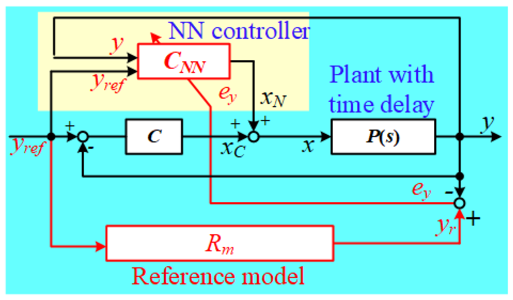
Figure 1. Block diagram of proposed reference-model-based ANN control system.
Processes 08 00050 g001
Figure 2. Step response of FOPTD plant.
Processes 08 00050 g002
Figure 3. Structure of conventional I-PD control.
Processes 08 00050 g003
Figure 4. Structure of conventional error feed back ANN control method.
Processes 08 00050 g004
Figure 5. Comparison simulation results. (a) Time response of the conventional error feed back ANN control method and (b) Time response of the proposed reference-model-based ANN control method.
Processes 08 00050 g005
Figure 6. Experimental setup.
Processes 08 00050 g006
Figure 7. Simulation results. (a) Time response for the controlled system and (b) results of positive direction control for proposed control system and conventional I-PD control system for temperature increase from 100 ° C to 105 ° C obtained from simulation.
Processes 08 00050 g007
Figure 8. (a) Outputs of ANN controller and I-PD controller and (b) control input obtained from simulation.
Processes 08 00050 g008
Figure 9. Experiment results. (a) Time response for the controlled system and (b) results of positive direction control for proposed control system and conventional I-PD control system for temperature increase from 100 ° C to 105 ° C obtained from experiments.
Processes 08 00050 g009
Figure 10. (a) Outputs of ANN controller and I-PD controller and (b) control input obtained from experiments.
Processes 08 00050 g010