Article

Cooling Performance Assessment of a Slinky Closed Loop Lake Water Heat Pump System under the Climate Conditions of Pakistan

by
Muhammad Kashif Shahzad
1,
Mirza Abdullah Rehan
2,*,
Muzaffar Ali
1,
Azeem Mustafa
2,*,
Zafar Abbas
2,
Muhammad Mujtaba
2,
Muhammad Imran Akram
2 and
Muhammad Rabeet Yousaf
2
1
Energy Engineering Department, University of Engineering and Technology, Taxila 47080, Pakistan
2
Department of Mechanical Engineering, Pakistan Institute of Engineering and Technology, Multan 60000, Pakistan
*
Authors to whom correspondence should be addressed.
Processes 2019, 7(9), 553; https://doi.org/10.3390/pr7090553
Submission received: 25 May 2019 / Revised: 15 July 2019 / Accepted: 19 July 2019 / Published: 22 August 2019

Abstract

:
This paper presents an experimental evaluation of a closed loop lake water heat pump (LWHPs) system based on the slinky coiled configuration. Initially, a mathematical model is developed in the Engineering Equation Solver (EES) for the heat pump system and the submerged coils in a lake. System performance is determined for the submerged slinky copper coils under the various operating conditions. Afterwards, parametric analysis is performed considering different influencing parameters, such as the lake water temperature, ambient temperature, and mass flow rate of the circulating fluid at constant lake depth of 4 ft. The experimental setup is developed for 3.51 kW cooling capacity after cooling load calculation for a small room. In the current study, slinky copper coils are used to exchange heat with lake water. The experimental setup is installed in Taxila, Pakistan, and the system’s performance is analyzed during selected days. After experimentation based on hourly and daily operation characteristics, it is observed that the lake water temperature has significant influence on the heat transfer rate between slinky coil and lake water. While the lake water temperature in summer decreases and increases in winter with the depth. The resulted daily average coefficient of performance (COP) of the system is within the range of 3.24–3.46 during the selected days of cooling season. Based on these results, it can be concluded that the LWHP systems can be considered a viable solution for Pakistan having a well-established canal system.

1. Introduction

The need for alternative and efficient means of energy generation is now undeniable, as Pakistan is facing a severe energy crisis at this time due to the electricity shortfall. In this regard, the Government is taking steps to overcome this crisis by 2025 but there is a need of more efficient air-conditioning systems in order to accommodate the changing face of energy provision, because Pakistan is considered to be one of those countries with some of the highest energy consumption for domestic use in the world. Domestic annual energy consumption in Pakistan is about 45.9%, while for the industrial sector, use is about 27.5% of the total energy. About 37% of the total energy is being consumed for HVAC applications [1]. Therefore, it is obvious from the facts that the energy being consumed is significant to maintain comfortable indoor conditions for human beings. Improvement in the efficiency of the available systems and utilization of efficient air-conditioning technologies can be effective to enable reduction in costs, energy consumption and the provision of a healthy environment.
Comfortable air-conditioning provision in buildings often requires a significant amount of energy. To main the indoor zone in the comfort range, separate cooling and heating systems are normally used and these systems use energy which is produced from depleting energy resources like fossil fuels and others. About 46% of solar energy in the form of radiations is absorbed by the earth, including water resources. This absorbed energy can be used for cooling and heating purposes using ground source heat pumps (GSHPs). These ground source heat pumps including ground water heat pumps, ground coupled heat pumps and surface water heat pumps (SWHPs) are often referred to as geothermal heat pumps (GHPs). These systems have become increasingly popular because of their outstanding cooling and heating performance as compared to conventional air conditioning systems. Moreover, these systems can offer significant reductions in electricity consumption by providing a high-level comfort, and they are also environmentally friendly systems [2,3].
SWHP system is one such technology, and it can play a key role in maintaining comfort conditions in an efficient way, thus reducing the electricity demands for air-conditioning. SWHP systems using surface water as a heat source for heat pumps are a relatively low cost and efficient heat pump in relatively warm climate conditions [4] and can be either open or closed loop systems. In open loop systems, surface water is pumped through a heat exchanger used in place of an air source heat exchanger in the heat pumps and is drained out to the water source at some distance. A closed loop system consists of a piping coil submerged in the water body at certain depth. The piping loop is used to extract heat from the water body to the water or antifreeze solution contained in the coil and circulate it through the water-refrigerant heat exchanger and to the submerged coil. As compared to open loop systems, closed loop systems are more efficient due to less pumping consumption of water to the heat pump system [5].
Prior to the current study, many studies have been presented previously on the performance, design of the system and coil configuration for closed and open loop water-based heat pump systems. Kavanaugh and Pezent (1991) presented their work on the design and performance investigation on such heat pump systems utilizing surface water as source of energy in Alabama, in southern USA. Seasonal variation of temperature in the lake and different coil designs were discussed briefly. But the outcomes of their study did not specify whether the heat transfer results indicated on graphs were for the coils or the heat transfer rate in the space [6]. Peer and Joycs (2002) developed a thermal model for lakes using an open loop system for direct cooling purposes in the Cornell University campus [7]. Similarly, Xiao Chen et al. (2006) performed a performance analysis using open loop lake water heat pump systems [8].
The dynamic heat transfer process between coils and lake water was not modeled, and the heat transfer rate was assumed as a constant value. Chiasson et al. developed a model to simulate the performance of a shallow pond as a supplemental heat rejecter for ground-coupled heat pump systems [9]. Thermal stratification of the surface water was neglected. The outlet fluid temperature of submerged coils and the average pond temperature were computed iteratively. X. Chen and G. Zhang (2013) performed a study on closed loop SWHPs considering thermal stratification in the climates of China using the spiral coils of an HDPE pipe [10].
Ji Liang et al. (2011) performed an analysis to evaluate the performance of shallow water heat pump systems in china, arguing that high performance results can be obtained using stable water temperature in shallow lakes instead of deeper water [11]. Pengfei Si et al. (2015) have presented an optimized model for river water temperature calculation for water source heat pump systems, to check the energy potential in the source [12].
It can be seen from the aforementioned literature review that surface water heat pump (SWHP) technology is being used in various parts of the world but its implementation in Pakistan is rarely analyzed. Some studies have been performed on geothermal potential in Pakistan, but nothing has been found at a technological level [13,14]. Therefore, this work is based on the experimental investigation performed on surface water heat pump systems (SWHPs) at Taxila, Pakistan. In this study, a slinky coiled type heat exchanger constructed using copper coils was used instead of an HDPE pipe, which has a higher thermal conductivity and surrounds less surface area for heat transfer. The system was designed for 1-ton heating and cooling capacity. The experimental setup was established at a fresh canal/lake water passing nearby the University of Engineering and Technology Taxila, Pakistan with the intent of determining slinky lake water heat exchanger’s performance under heat extraction and heat rejection conditions. This study was performed to investigate the performance and potential viability of such LWHPs leading to district cooling in Pakistan by having a well-established canal system.

2. Mathematical Modelling

The system under investigation consisted of a slinky copper coil submerged in the lake water, and a water-to-air heat pump, which was used for the cooling of a test room. The lake was utilized as heat source-sink of closed-loop.

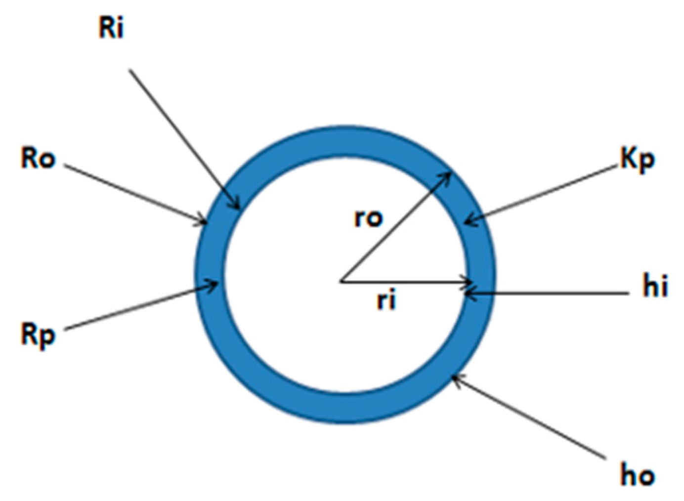
2.1. Heat Transfer Model of Submerged Heat Exchanger (HX)

2.1.1. External Convection Heat Transfer Coefficient of Coil

Heat transfer between the reservoir and submerged slinky copper coils can be modelled as natural convection on the outer side of coils. Chiasson et al. calculated the coefficient of heat convection at the external surface of the slinky coils submerged in the water by using the relation for natural free convection for horizontal cylinder [9]. However, the thermal interference among pipes causes the actual HTC of coils to be considerably less than the theoretically calculated value. In this model, two experiential formulae based on measured values of HTC of tested coil under various conditions are used for calculating the HTC of coils for the sake of modeling accuracy improvement. The Rayleigh number is calculated by Equation (1).
R a = g β ( Δ T ) L 3 v α  
The Prandtl number is calculated by Equation (2).
P r = C p . μ k
A correlation used in this model for free convection in coils is defined as (Churchill et al.) [15].
N u o = ( 0.60 + 0.387 R a 1 6 ( 1 + ( 0.599 P r ) 9 16 ) 8 27 ) 2
The convection coefficient at the external pipe surface h o can be calculated by Equation (4).
h o = N u o . K L

2.1.2. Internal Convection Heat Transfer Coefficient of Coil

The internal convection heat transfer coefficient of the submerged coils in the lake is forced convection due to turbulent flow. Gnielski presented a correlation to calculate the Nusselt number in the case of forced convective heat transfer. This correlation is applicable for a Reynold’s number ranging more than 4000 [6]. The relation for Nusselt number is calculated by Equation (5).
N u i = f 8 ( R e 1000 ) P r 1 + 12.7 f 8 ( P r 2 3 1 )
The Reynold’s number, Darcy’s friction factor for (Re ≤ 5 ×   10 6 ) and internal convective heat transfer coefficient are found by Equations (6)–(9):
R e = v . D ϑ
f = 1 ( 0.790 ln ( R e ) 1.64 ) 2
  h i = N i . K L

2.1.3. Overall Heat Transfer between the Submerged Coil and Lake Water

A closed loop involves the calculation of overall heat transfer rate between the fluid circulating in loop and the lake water. The relative magnitude of the components limiting the lake coil heat transfer rates can best be seen by incorporating the thermal resistance concept. Thermal resistances influencing heat transfer rate in slinky coils are shown in Figure 1.
The rate heat transfer in the copper pipe is calculated by Equation (9) [6].
Q = T w T a v g R i + R p + R o
Thermal resistances including internal, external and due to pipe material R p can be calculated by using the relation of h o and h i in Equations (10)–(12).
R i = 1 2 π r i L h i
R i = 1 2 π r o L h o
R p = ln ( r o r i ) 2 π k p L
In Equation (9), Tavg can be found if the values of Tin and Tout are known, while Tin is the temperature of the fluid in coils after exchanging heat with the lake water and before entering the co-axial heat exchanger [16]. It is given by Equation (13).
T i n = T w + Q l o a d . M . C p
Tout is the fluid’s temperature after exchanging its heat with refrigerant in the co-axial heat exchanger and is given by Equation (14).
T o u t = T i n + Q l o a d . M . C p
Here Cp is the specific heat capacity of the fluid (water) flowing through the slinky coils [J/K/Kg]. “M” is the mass flow rate of the fluid. The emissivity of copper coils is taken as 0.85 [17] and the average temperature Tavg of the fluid inside the coils is calculated by Equation (15).
T a v g = T i n + T o u t 2
It was assumed that the heat transfer with the greatest thermal resistance is that between the lake water and surface of slinky coils, and as such, transfer through the walls of heat exchanger and between the inner surface and the fluid inside is not considered. It is justified that heat transfer due to natural convection is known to be significantly lower than that due to forced convection, as will be experienced in the heat exchanger, and the walls of the heat exchanger can be assumed to be thin and thus conduction will be negligible.

2.2. Heat Pump Performance Model
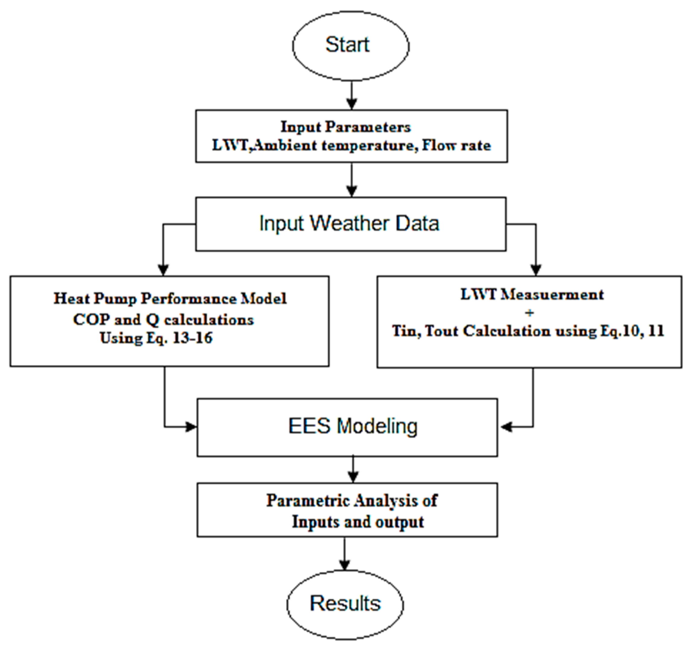
The temperature measurements of the inlet and outlet water were taken after a specific interval of time i.e., 10 min through the co-axial heat exchanger to calculate the heat extracted from the co-axial heat exchanger and lake water. The inlet and outlet temperatures of the refrigerant passed through the condenser were measured to calculate the heating capacity. Inlet and outlet air temperature were measured for load calculation purpose. The values of the voltage and current for the compressor, fan, and pump were recorded after interval of time to calculate their power. These measurements were used to evaluate the performance of heat pump system. A schematic diagram of LWHPs is shown in Figure 2.
The parameters to be calculated based on the experimental data are described as:
Heat extracted from evaporator q ˙ evp through submerged slinky coils and the heat extracted from the condenser is given by Equations (16) and (18), respectively. Here m ˙ w is the mass flow rate of water passed the evaporator, (hinhout) is the water enthalpy difference between inlet and outlet of evaporator [18]. The heat extract from water q ˙ w is considered equal to heat extract of evaporator q ˙ evp.
q ˙ e v p   =   m ˙ w   .   ( h i n h o u t )
q ˙ w = q ˙ e v p
q ˙ c o n d =   m ˙ r   ( h 3     h 2 )
Here q ˙ cond is the heating capacity and (h3h2) is the refrigerant enthalpy difference between inlet and outlet of condenser. r is the mass flow rate of refrigerant. The energy efficiency of the LWHP unit [16] and the whole system can be defined by Equation (19).
C O P h p = q ˙ c o n d W c

2.3. EES Modeling

To compare the experimental results with the theoretical results, an Engineering Equation Solver (EES) model was developed using heat and mass balance equations, co-relations for submerged slinky coils and heat pump performance parameters. Parametric analysis for the system performance (COP and heat capacity) was carried out using input parameter e.g., lake water temperature, ambient temperature and flow rate. A schematic flow chart of the EES model is shown in Figure 3.

3. Experimental Setup

The experimental setup (previously shown in Figure 2) used for the experimentation purposes consists of the test room for the experimental usage, slinky lake water coils of copper and the refrigerant circuit, which is the heat pump system.

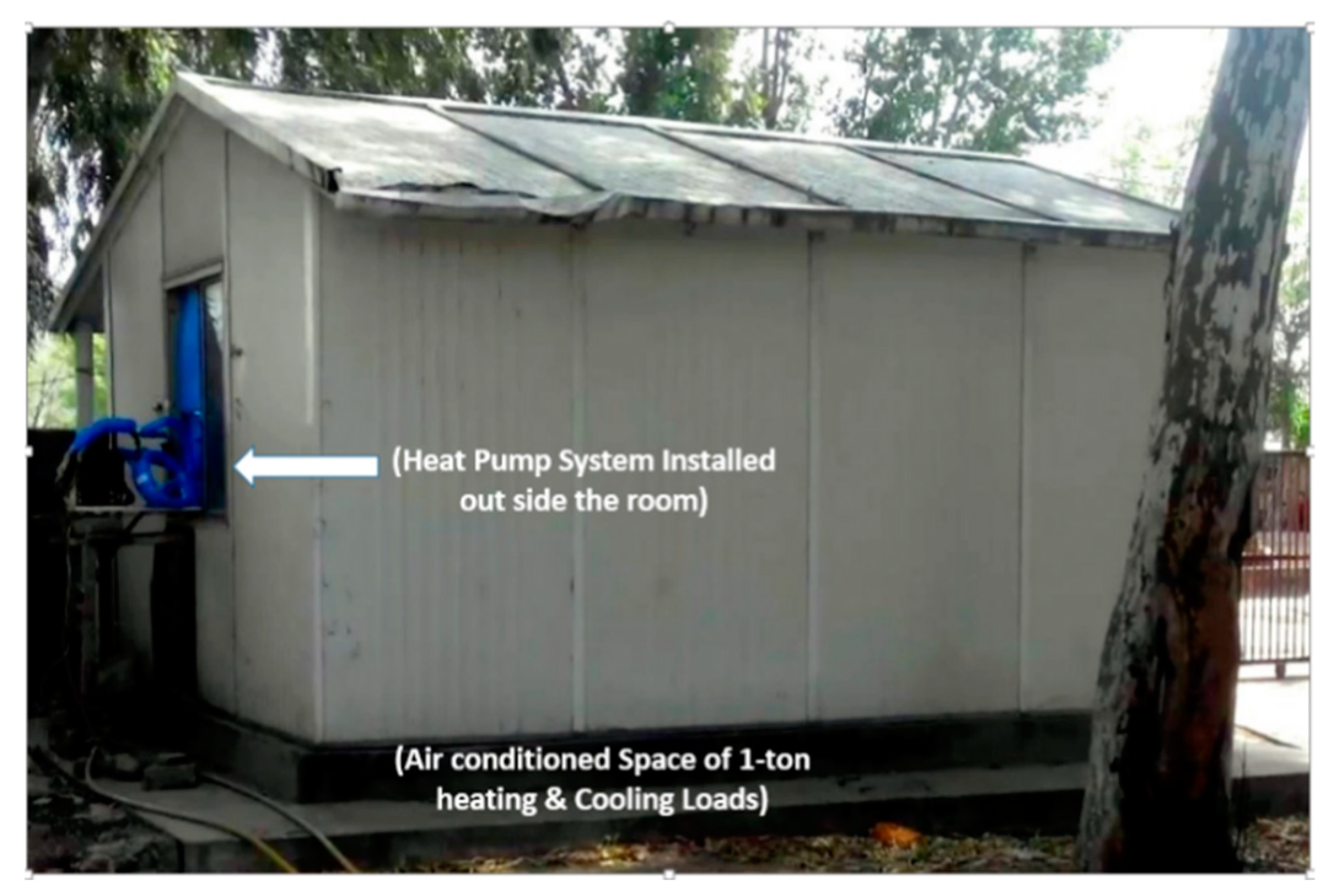
3.1. Test Room Used for Experimental Purposes

For the experimental purpose, a cabin of dimensions (10.5 × 14 × 11) with two windows (east and west) with single glazing was used, as shown in Figure 4. The cabin’s total heating and cooling load calculated were 1.14-ton and 1.06-ton, respectively.

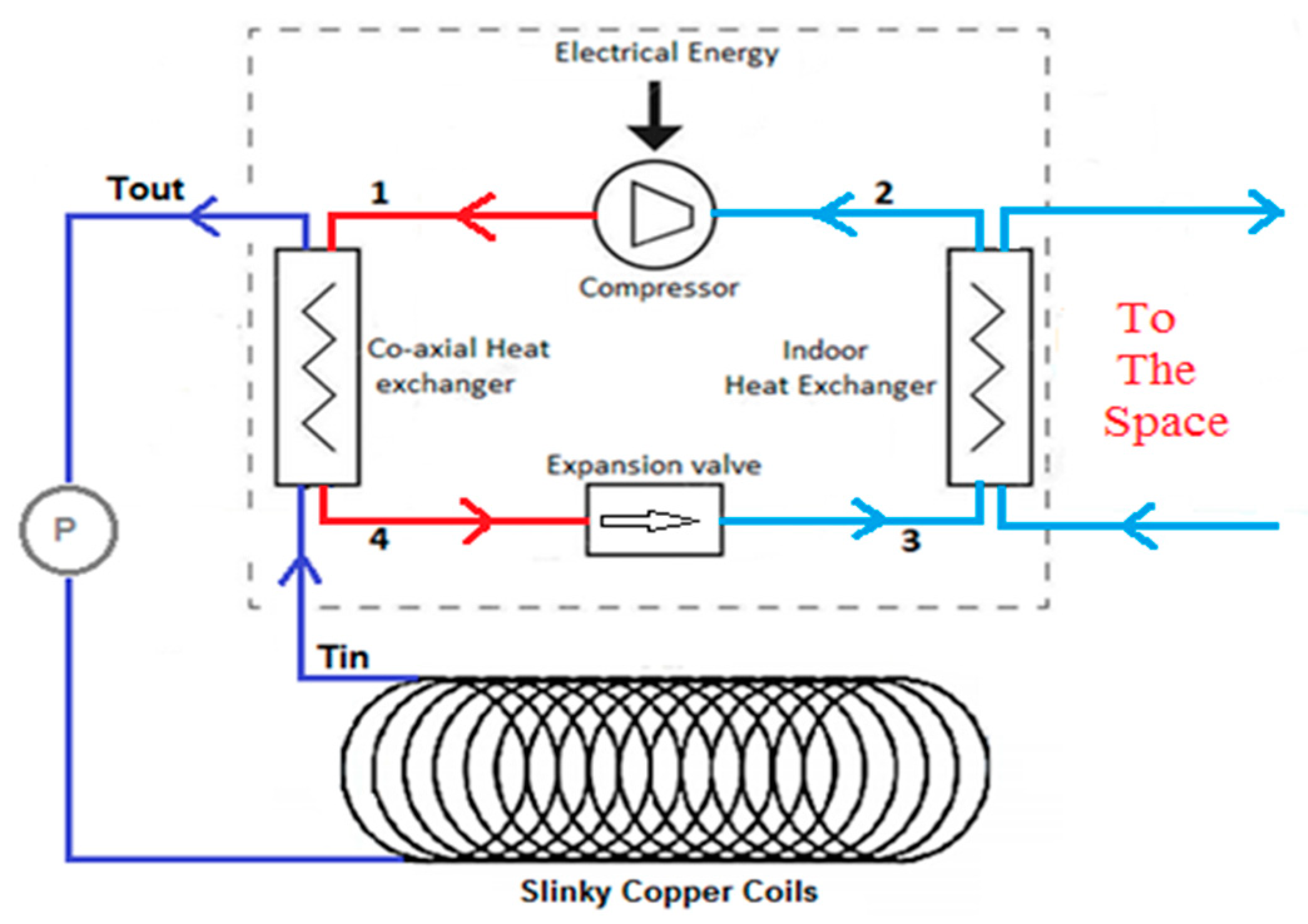
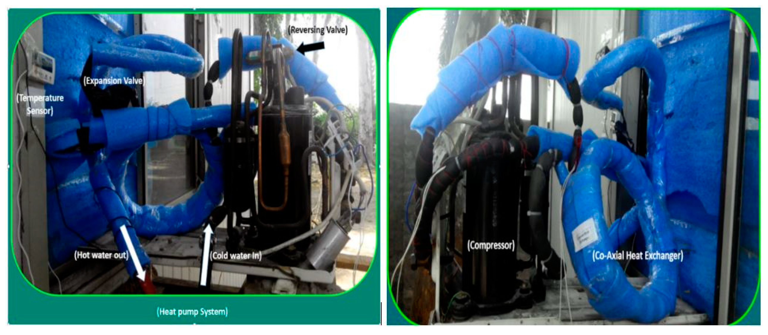
3.2. Heat Pump/Reversible Vapor Compression System

Keeping in view the cooling load of the test space, thermodynamic modeling for a heat pump system of 1-ton capacity was performed, and the experimental task was accomplished by using a simple reversible air conditioning system of one-ton capacity. In order to utilize the thermal potential of lake water air-cooled, the condenser was replaced with a co-axial liquid to liquid heat exchanger. The installed heat pump system is shown in Figure 5. A fan coil arrangement is used to exchange heat with room air and was installed inside of the cabin.
The lake water heat pump system included two loops, a refrigerant (R410-A) vapor compression loop and the other coil’s loop submerged in water containing an antifreeze solution (aqueous solution of ethylene glycol) as circulating fluid. To make heat transfer possible between the refrigerant and antifreeze solution, a liquid to liquid heat exchanger was used, as shown in Figure 6.

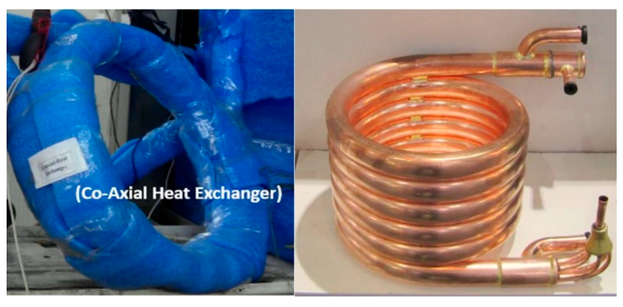
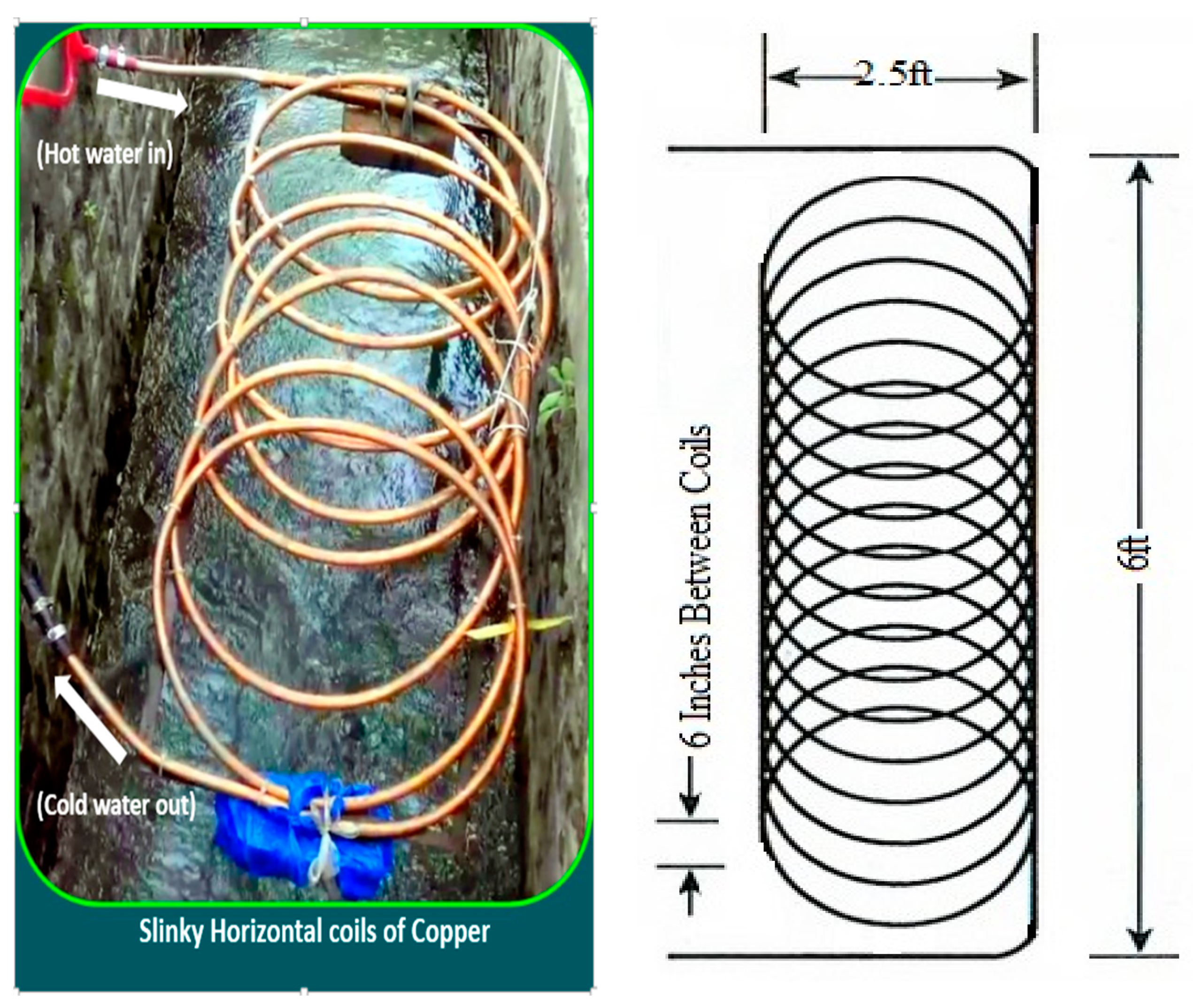
3.3. Lake Water Heat Exchanger

One of the main factors behind convection heat transfer coefficients at outer surface of heat exchangers is the configuration. Previous studies related to the heat exchangers identified that heat transfer capacity reduces when the tubes are more densely packed into a confined area. In order to make a heat exchanger with better capacity, its size and configuration should be refined. To achieve this, different devices such as slinky assembly guide rails, a metal suspension frame and different spacers were designed, fabricated, and utilized.
In order to construct a slinky coil from the 60 ft copper pipe, a guide rail system and spacers were designed. The guide rail system was built such that the center to center loop diameter was 2.5 ft while the guide length was 6 ft. The length of spacer used for coils were set equal to the pitch of coil. Zip ties were used to wrap up the coil to prevent it from unraveling. Figure 7 shows a slinky coil set fabricated using guides and rails. To circulate the fluid in slinky coil’s loop a 0.5 hp circulating pump was used. A water storage tank was used to store and make the circulating fluid level in coil.

3.4. Sensors

3.4.1. Temperature Sensors

For the experiments, k-type thermocouples were used to measure temperatures with the help of digital temperature meter (TES 1310). To measure the temperatures of the circulating fluid, Tin and Tout in-pipe thermocouple probes were used. To measure LWT at different depth, four thermocouples attached to a steel rod at a distance of 1-ft were used.

3.4.2. Flow Meter

A doppler flow meter (HFM-3A) was used for testing purposes from Dynamic Fluid System Inc. The flow measurement range of this instrument was (0.5–20) GPM with uncertainty of ±1% in the full-scale flow measurement.

4. Results and Discussion

The performance investigation for the heat pump system was initially executed by obtaining thermal results from the reservoir during the selected days of experimentation. The measurements of the temperature were performed after every 10 min for the inlet and outlet water temperature through the co-axial heat exchanger to calculate the heat extracted from the slinky coils and ground. Then temperature measurements were made for the heat pump system about indoor heat exchanger to determine the cooling capacity of the system. These results were used to find the COP of the heat pump system during the selected days of summer.

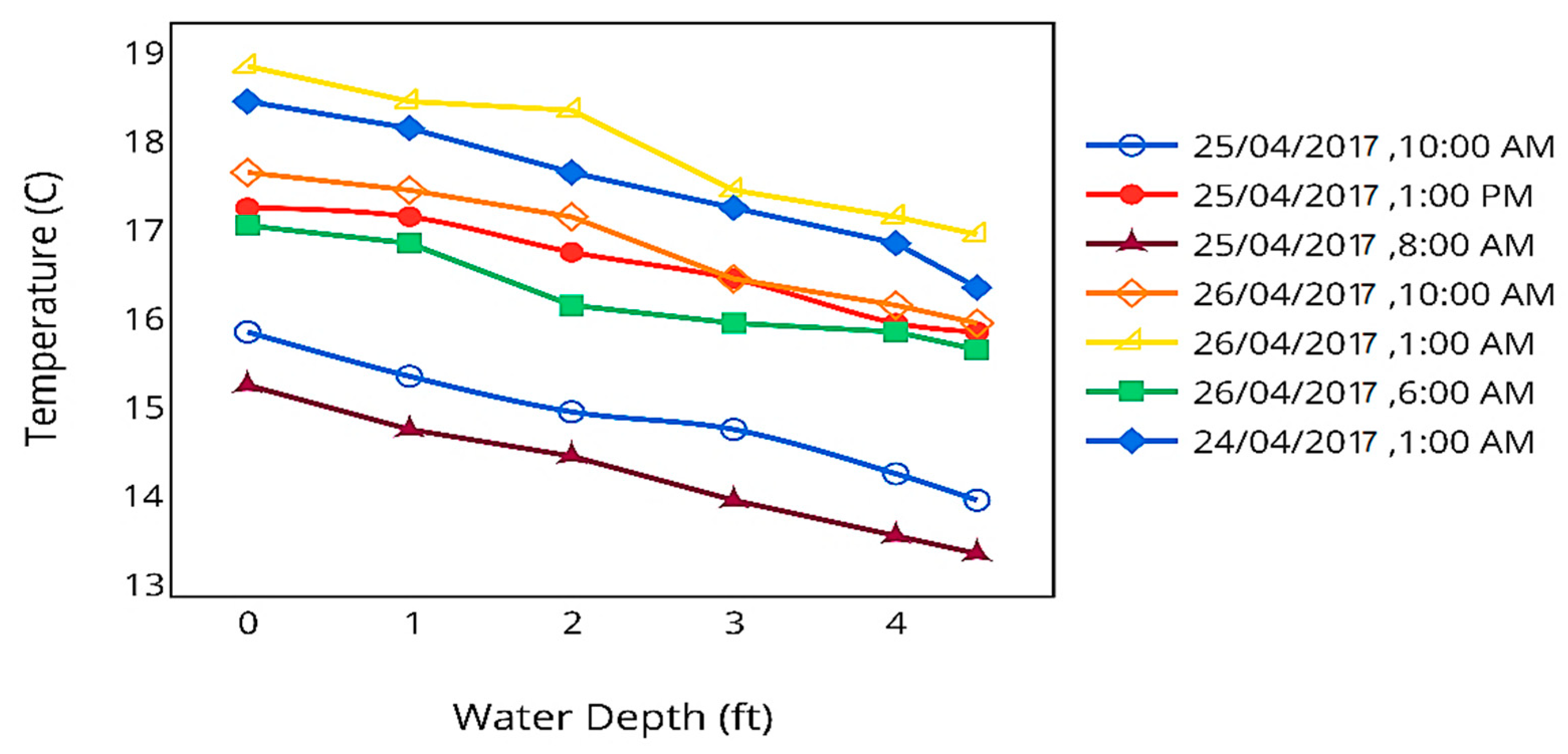
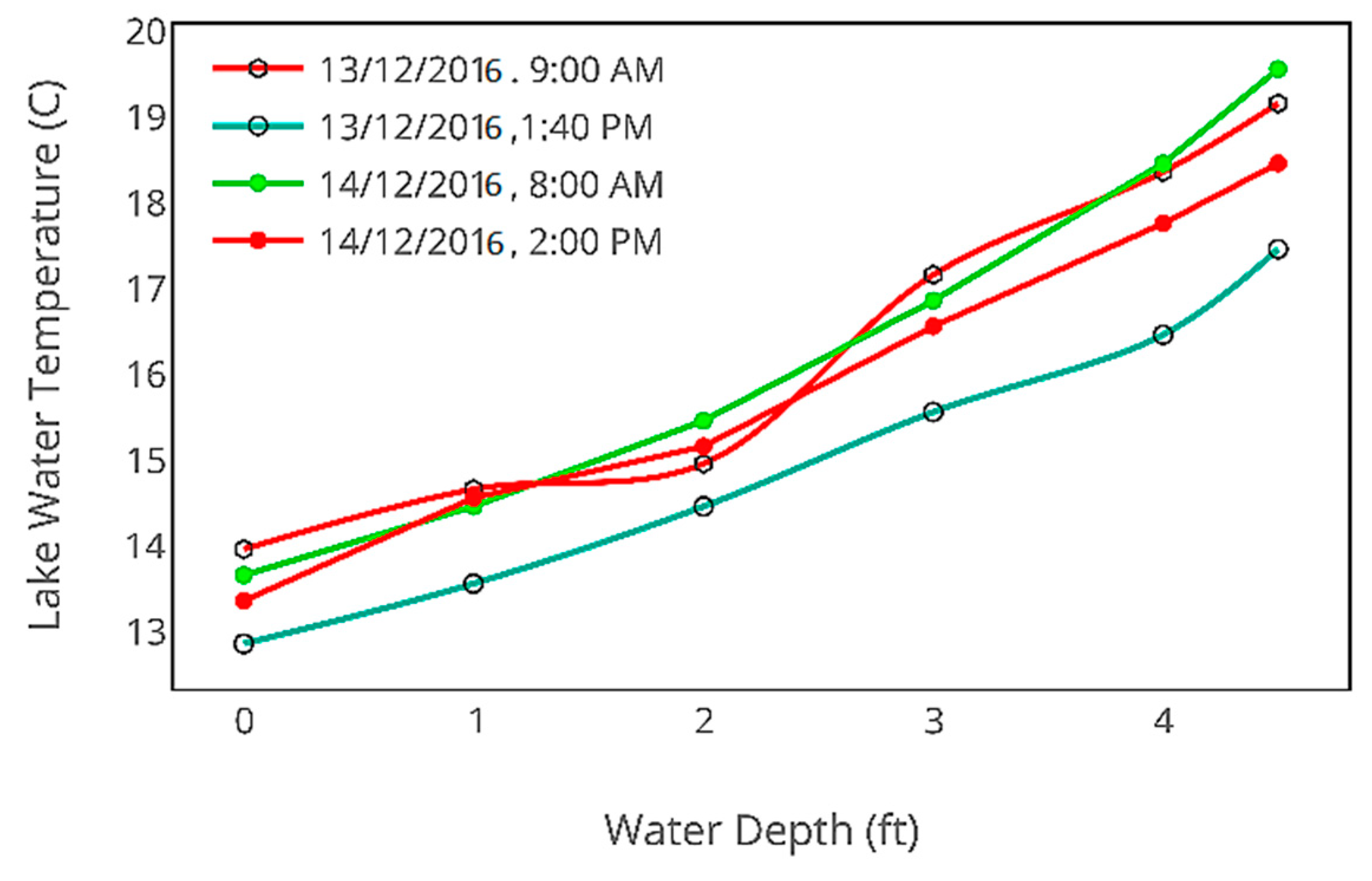
4.1. Effect of Lack Depth on Water Temperature

Measurements of the reservoir temperature were performed at the canal passing nearby the University of Engineering and Technology, Taxila on 13 December 2016 to 24 April 2017. Temperature measurements with respect to depth were taken in the heating and cooling seasons. Figure 8 and Figure 9 show the relation between the temperature change with respect to depth such that rises or falls during the heating and cooling season, respectively in correspondence with the depth of the lake water.
A second point to note is the thermal stratification that exists in the reservoir having a variation of 1–2 °C difference between the top and bottom layers as shown in Figure 8 and Figure 9. This shows the thermal behavior of different layers with depth.
It can be clearly seen from Figure 8 and Figure 9 for the lake water temperature and depth that the water temperature increases with depth in winter while decreases in summer. The reason is that the heat absorbed by the surrounding earth area during the summer season gets transferred to the water and is used in the winter. The lake water temperature is more than that of the ambient air during the winter season and less than ambient air temperature in summer. It means that the at higher depths lake water temperature will be more suitable as a heat source for the heat pumps.

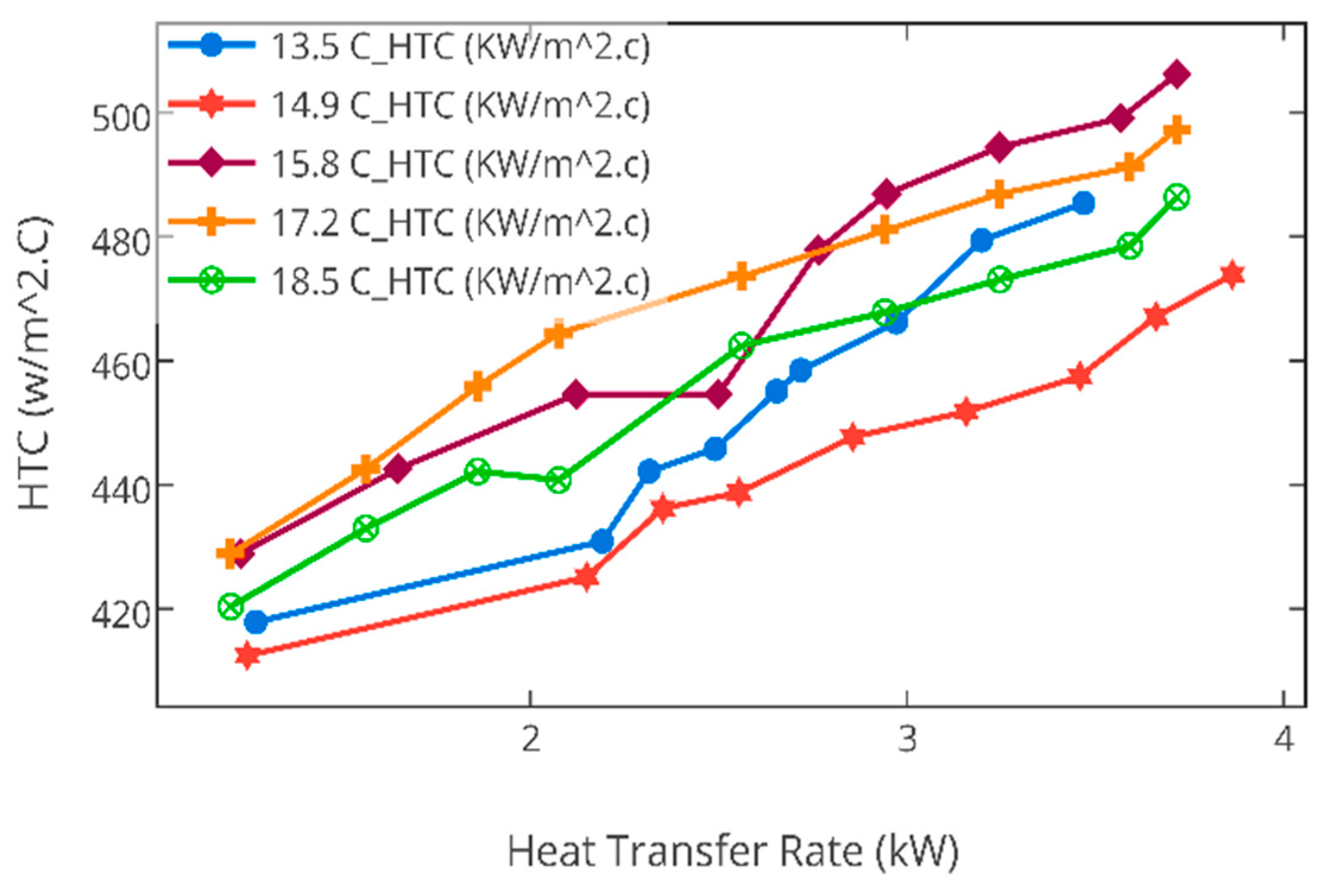
4.2. Effect of Heat Transfer Rate through Slinky Coils on Heat Transfer Coefficient

The experimental apparatus is shown in Figure 2 with slinky coils of copper. Slinky coils were placed in the lake and the other apparatus was set on the bank. Four k-type thermocouples were used to take measurements of lake water temperature. Flow meter and regulating valves were used to regulate the flow and study its effect on the heat transfer rate.
To investigate the effect of heat transfer rate and LWT on the HTC of submerged coils, heat transfer rate and heat transfer co-efficient HTC were calculated at different LWTs during the experimental hours. The measured HTCs under with different LWTs and the effect due to different heat transfer rate are shown in Figure 10.
In general, the HTC for the same LWT decreases with the decrease in the heat transfer rate. It can be attributed to the fact that the decrease in the heat transfer rate results in the decrease in temperature difference between the coil surface and the lake water, which leads to a reduction in the natural convection heat transfer coefficient. The HTC for the same heat transfer rate decreased with the drop of LWT, and the HTC in heat rejection mode was larger than that in heat extraction mode as a whole. This is because the decrease in LWT causes a reduction in natural convection heat transfer coefficient according to natural convection mechanism.
In order to investigate, the effect of varying flow rate of circulating fluid on the HTC between the lake water and the circulating fluid in slinky coils, flow rate was varied between 2–3 GPM. Hence it was observed that by the increase of flow rate HTC was also increased and by decreasing the flow rate HTC was decreased, as shown in Figure 11. The rise in HTC is due to direct proportionality of HTC with the mass flow rate of circulating fluid.

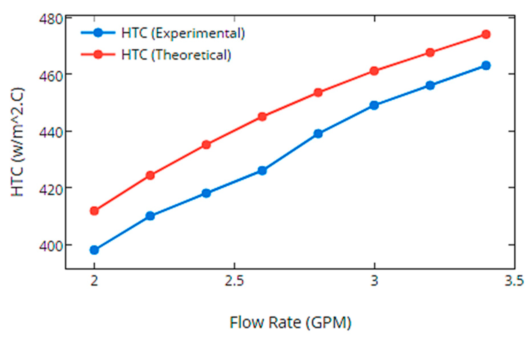
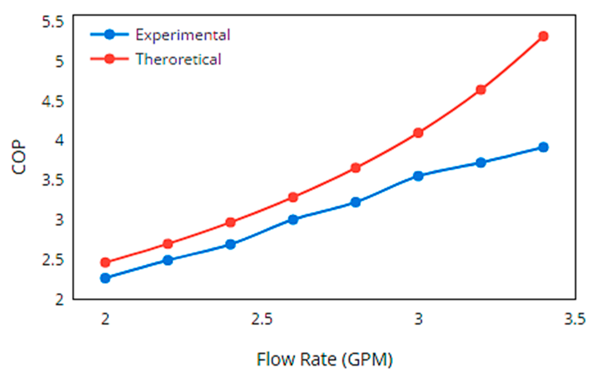
4.3. Performance Results of Heat Pump

As LWHPs primarily depend on the lake water temperatures and have better performance as compared to other air source heat pumps due to greater temperature difference between the fluid and refrigerant. Figure 12 shows the COP on daily basis during the cooling season. It can be seen that the system is less sensitive to the ambient conditions. However, the system’s COP is dependent on the lake water temperature. The lower the water temperature (Tw), the higher the cooling performance will be due to the greater temperature difference between the fluid and refrigerant temperatures.
The lake water heat pump’s performance is primarily dependent on the flow rate of the circulating fluid in slinky coils. As the rate of heat transfer is directly proportional to the flow rate of fluid and as heat transfer rate is directly related to the flow rate of the fluid and the temperature difference between the refrigerant and the circulating fluid in the co-axial heat exchanger. Therefore, the COP of the LWHPs increases with the flow rate and relation as shown in Figure 13. The difference between the experimental and theoretical trends reveals that an exponential growth in COP occurs with increase in flow rate. However, experimental results are found to be in good agreement with theoretical results, qualitatively.

5. Conclusions

The performance evaluation of closed loop LWHP system was carried out in Taxila, a city in Pakistan, by developing an experimental setup and using canal water as a heat source passing nearby the University area. Experiments were performed for the selected cooling days of summer and it was observed that the lake water temperature has significant influence on the heat transfer rate between slinky submerged coils and lake water. Lake water temperature measurements supported the fact that the water temperature decrease with the increase of depth during the summer. So, the deeper lakes will have the better performance due to higher temperature gradients. The resulting daily average coefficient of performance (COP) of the system is within the range of 3.24–3.46 during the selected days of cooling season. These systems have performance advantage over air source systems and can cut down the rising energy issues due to their better performance results. Based on these results, it can be concluded that such LWHP systems can be considered as a viable solution for Pakistan having a well-established canal system.

Author Contributions

Conceptualization, M.K.S.; Formal analysis, M.A.; Investigation, M.A.; Methodology, M.K.S., M.A.R. and A.M.; Validation, M.A.R. and A.M.; Writing—original draft, M.K.S.; Writing—review & editing, M.A.R., A.M., Z.A., M.M., M.I.A. and M.R.Y.

Funding

This research received no external funding.

Conflicts of Interest

The authors declare no conflict of interest.

Nomenclature

vKinematic Viscosity of lake water [ m 2 s 1 ]
R a Rayleigh number
P r Parantal Number
C p Specific heat of water [ J . Kg 1 . K 1 ]
μDynamic viscosity of fluid [kg.m−1.s−1]
K w Thermal Conductivity of water [W.m−1.K−1]
N u o Outside Nusstlet Number
N u i Internal Nusselt Number
D o Outside diameter of pipe [inch]
K p , KThermal Conductivity of copper pipe [ W / m K ]
f Darcy friction factor
R e Renoyld Number
h o External convective coefficient of slinky coils [ W m 2 . C ]
h i Internal convective coefficient of slinky coils [ W / m 2 . C ]
Effectiveness of submerged copper coils
g Acceleration due to gravity [ m s 2 ]
αThermal diffusivity   [ m 2 s 1 ]
R _ i Internal thermal resistance of pipe
R p Thermal resistance of copper pipe
R _ o Thermal resistance outside the pipe

Abbreviation

HDPEHigh Density Polyethylene
HVACHeating Ventilation and Air Conditioning
LWHPLake water Heat Pump System [ W / m 2 K ]
LWTLake water temperatures [C]
HTCOverall heat transfer coefficient

References

  1. Kavanaugh, S.P. Field test of vertical ground-coupled heat pump in Alabama. ASHRAE Trans. 1992, 98, 607–616. [Google Scholar]
  2. Kavanaugh, S.P. Development of design tools for ground-source heat pump piping. ASHRAE Trans. 1998, 104, 932–937. [Google Scholar]
  3. Sohail, M.; Qureshi, M.U.D. Ahmed Sohail and Moin ud Din Qureshi, Energy efficient buildings in Pakistan. Sci. Vis. 2010, 16–17, 27–38. [Google Scholar]
  4. American Society of Heating Refrigerating and Air-Conditioning Engineers. ASHRAE Handbook-HVAC Applications; American Society of Heating Refrigerating and Air-Conditioning Engineers: Atlanta, GA, USA, 2011. [Google Scholar]
  5. Kavanaugh, S.P.; Rafferty, K. Ground-Source Heat Pumps-Design of Geothermal Systems for Commercial and Institutional Buildings; American Society of Heating Refrigerating and Air-Conditioning Engineers: Atlanta, GA, USA, 1997. [Google Scholar]
  6. Kavanaugh, S.P. Ground and Water Source Heat Pumps—A Manual for the Design and Installation of Ground-Coupled, Ground Water and Lake Water Heating and Cooling Systems in Southern Climates; University of Alabama: Tuscaloosa, AL, USA, 1991. [Google Scholar]
  7. Peer, T.; Joyce, W.S. Lake Source Cooling. ASHRAE J. 2002, 44, 37–39. [Google Scholar]
  8. Chen, X.; Zhang, G.; Peng, J.; Lin, X.; Liu, T. The performance of an open-loop lake water heat pump system in south China. Appl. Therm. Eng. 2006, 26, 2255–2261. [Google Scholar] [CrossRef]
  9. Chiasson, A.D.; Spitler, J.D.; Rees, S.J. A model for simulating the performance of a shallow pond as a supplemental heat rejecter with closed-loop ground source heat pump systems. ASHRAE Trans. 2002, 106, 107–121. [Google Scholar]
  10. Chen, X.; Zhang, G. On the study of closed-loop lake water heat pump applications in south China climates. Energy Build. 2013, 6. [Google Scholar]
  11. Liang, J.; Yang, Q.; Liu, L.; Li, X. Modeling and performance evaluation of shallow ground water heat pumps in Beijing plain, China. Energy Build. 2011, 43, 3131–3138. [Google Scholar] [CrossRef]
  12. Si, P.; Li, A.; Rong, X.; Feng, Y.; Yang, Z.; Gao, Q. New optimized model for water temperature calculation of river-water source heat pump and its application in simulation of energy consumption. Renew. Energy 2015, 84, 65–73. [Google Scholar] [CrossRef]
  13. Zaigham, N.A. Geothermal Energy Resources of Pakistan. In Proceedings of the World Geothermal Congress 2005, Antalya, Turkey, 24–29 April 2005. [Google Scholar]
  14. Bakht, M.S. An Overview of Geothermal Resources of Pakistan. In Proceedings of the World Geothermal Congress 2000, Kyushu, Japan, 28 May–10 June 2000. [Google Scholar]
  15. Churchill, S.W.; Chu, H.H.S. Correlating equations for laminar and turbulent free convection from a horizontal cylinder. Int. J. Heat Mass Transf. 1975, 18, 1049–1053. [Google Scholar] [CrossRef]
  16. Morton, A.C. Assessing the Performance of a Reservoir-Based Water Source Heat Pump; Renewable Energy Systems and the Environment; University of Strathclyde Engineering: Glasgow, UK, 2013. [Google Scholar]
  17. Hussen, H.M.; Hisham, A.H. Experimental model of ground source heat pump system. In Proceedings of the 7th Jordanian International Mechanical Engineering Conference (JIMEC’7), Amman, Jordan, 27–29 September 2010. [Google Scholar]
  18. Çağlar, A.; Yamali, C. Performance analysis of solar assisted heat pump with an evacuated collector for domestic heating. Energy Build. 2016, 54, 22–28. [Google Scholar] [CrossRef]
Figure 1. Pipe cross-section under different thermal resistances.
Processes 07 00553 g001
Figure 2. Schematic diagram of the lake water heat pumps (LWHPs) illustrating the inlet and outlets of each component.
Processes 07 00553 g002
Figure 3. Schematic flow chart for the Engineering Equation Solver (EES) parametric analysis.
Processes 07 00553 g003
Figure 4. Test room with installed heat pump system.
Processes 07 00553 g004
Figure 5. Installed heat pump systems with a co-axial heat exchanger.
Processes 07 00553 g005
Figure 6. Co-axial heat exchanger with and without insulation.
Processes 07 00553 g006
Figure 7. Submerged slinky copper coils.
Processes 07 00553 g007
Figure 8. Effect of the lake water depth on the lake water temperature in summer.
Processes 07 00553 g008
Figure 9. Effect of lake water depth on the lake water temperature in winter.
Processes 07 00553 g009
Figure 10. Showing a correlation between HTC and heat transfer rate w.r.t to LWTs.
Processes 07 00553 g010
Figure 11. Effect of flow rate on the heat transfer coefficient (HTC).
Processes 07 00553 g011
Figure 12. System performance during the selected experimental days w.r.t. Tamb and Tw.
Processes 07 00553 g012
Figure 13. Coefficient of performance (COP) of the LWHP system showing with flow rate of circulating fluid.
Processes 07 00553 g013

