Article

Finite Time Thermodynamic Optimization of an Irreversible Proton Exchange Membrane Fuel Cell for Vehicle Use

College of Automobile and Traffic Engineering, Nanjing Forestry University, Nanjing 210037, China
*
Author to whom correspondence should be addressed.
Processes 2019, 7(7), 419; https://doi.org/10.3390/pr7070419
Submission received: 17 June 2019 / Revised: 27 June 2019 / Accepted: 28 June 2019 / Published: 3 July 2019
(This article belongs to the Special Issue Thermodynamics: Modeling and Simulation)

Abstract

:
A finite time thermodynamic model of an irreversible proton exchange membrane fuel cell (PEMFC) for vehicle use was established considering the effects of polarization losses and leakage current. Effects of operating parameters, including operating temperature, operating pressure, proton exchange membrane water content, and proton exchange membrane thickness, on the optimal performance of the irreversible PEMFC are numerically studied in detail. When the operating temperature of the PEMFC increases, the optimal performances of PEMFC including output power density, output efficiency, ecological objective function, and ecological coefficient of performance, will be improved. Among them, the optimal ecological objective function increased by 81%. The proton film thickness has little effect on the output efficiency and the ecological of coefficient performance. The maximum output power density increased by 58% as the water content of the proton exchange membrane increased from 50% to the saturation point. The maximum output power density increases with the operating pressure.

1. Introduction

PEMFC converts the chemical energy of hydrogen and oxygen directly into electricity. Its high efficiency and low emissions make it the main candidates for powering the next generation of electric vehicles. The basic structure and operation principle of PEMFC considered here are explained in Figure 1. The PEMFC consists of a dual electrode, a gas diffusion layer (GDL), a proton exchange membrane (PEM) and a catalytic layer. Under the action of the anode catalyst, hydrogen molecules are converted into hydrogen ions and electrons according to:
H 2 Pt 2 H + + 2 e
At the cathode of the PEMFC, after the air humidified by the humidifier, the humidified oxygen passes through the air flow channel of the cathode current collector to the cathode GDL. The oxygen in the cathode gas stream diffuses through the gas diffusion electrode towards the catalyst interface where it combines with the hydrogen protons and the electrons to form water according to:
2 H + + 2 e + 1 2 O 2 Pt H 2 O + H e a t
The overall reaction can be written as:
H 2 + 1 2 O 2 Pt H 2 O + H e a t + E l e c t r i c i t y
Finite time thermodynamics is a study of the optimal results of process with thermal phenomena occurring in a finite time, and the optimal performance of devices and systems with thermal phenomena operating in a finite time. Yuan [1] studied the physical and chemical properties of PEMFC by combining electrochemical, non-equilibrium thermodynamics and finite time thermodynamics. The article points out that it is possible to find the maximum output power and maximum output efficiency, as long as the minimum total entropy production rate is obtained. The minimum total entropy production is caused by the irreversibility of chemical reaction and heat transfer, which can be expressed as: Stot = (ΔH/T − ΔH/T0) + (Q/TQ/T0), T0 represents the ambient temperature. Yan [2] pointed out that the PEMFC model and results of the literature [1] are not appropriate for engineering use. The electrochemical reaction of an actual PEMFC is not completely irreversible, but rather has several types of irreversibilities. Therefore, when the actual fuel cell is working, only part of the ΔG is lost. However, Yuan [3] believes that the calculation of the total entropy production rate of the system and related environment is not correct in the literature [2], and other conclusions obtained from this are not established.
Yin [4] established a mathematical model of an irreversible phosphoric acid fuel cell (PAFC). Considering that the chiller (AR) can absorb the heat generated during the PAFC work, the mathematical model of PAFC-AR is built. Based on the finite time thermodynamic optimization theory, it is concluded that the maximum output power of PAFC-AR is 3.41% higher than the maximum output power of PAFC.
Wei [5] established a mathematical model of the entropy production and ecological performance coefficient of PEMFC based on the finite time thermodynamic theory. It is obtained that increasing the working temperature or increasing the working pressure will reduce the entropy production; increasing the working temperature or decreasing the thickness of the proton membrane will increase the ecological coefficient of performance. In addition, different objective functions such as ecological coefficient of performance ECOP, ecological objective function E and output power were optimized and compared. According to different optimization objectives of PEMFC, different optimization working intervals were obtained.
When optimizing the performance of PEMFC, researchers mostly use PEMFC output efficiency and total cost as the common optimization goal. Zhang et al. [6] used PEMFC’s maximum output efficiency and lowest cost as the synchronization optimization target. The multi-objective optimization model of PEMFC was established based on the current density, operating pressure, and the chemical calculation coefficient of air and hydrogen. Calculation result surface: When the optimal current density is 994 mA/cm2, the compromise solution of the Pareto front is obtained. At this time, the output efficiency is 0.5472, and the total cost is 280.3 $/kW.
Xue et al. [7] used the effective area of PEMFC and the air stoichiometric coefficient as the operational variables, and established an optimization model with independent efficiency and minimum cost as independent optimization targets. Taking the Ballard fuel cell as an example, the article breaks the barriers of traditional performance design and product cost not being considered at the same time, so that performance and production costs can enter the design stage and be optimized together.
Frangopoulos et al. [8] used the current density and operating temperature of the PEMFC system as operating variables, established an optimization model with independent efficiency and minimum cost as the independent optimization target, applied optimization techniques to determine the optimal design and operation mode of the PEMFC system, and considered the system was applied to a merchant ship as an example.
The remaining part of this article was arranged as follows. In Section 1, the irreversible model of fuel cell was established. In Section Results and discussion, the effect of different parameters on the optimal performance of PEMFC were discussed. The last section presented the important conclusions such as the operating temperature of the irreversible PEMFC increasing from 50 °C to 80 °C, the optimal output power density increasing by 16%, etc.

2. Finite Time Thermodynamic Model of Irreversible PEMFC

2.1. Reversible Output Voltage

The reversible output voltage of PEMFC can be obtained from the Nernst equation [9,10,11].
E r = Δ g f 0 n F + 1 n F { ( T 298.15 ) Δ h + R T [ ln ( a H 2 ) + 0.5 ln ( a O 2 ) ] }
In Equation (4), Er represents the reversible output voltage; T is the operating temperature; Δh is the standard molar enthalpy; R is a gas constant; and aH2 and aO2 are partial pressures of hydrogen and oxygen, respectively.
The partial pressures of hydrogen and oxygen can be expressed as [9]
a H 2 = 0.5 P H 2 O s a t [ 1 exp ( 1.653 i / T 1.334 ) x H 2 O s a t 1 ]
and
a O 2 = P [ 1 x H 2 O s a t x 0 t h e r g a s e s c h a n n e l exp ( 0.29 i / T 0.832 ) ]
The mole fraction of water in saturation can be expressed as
x H 2 O s a t = P H 2 O s a t P
Saturated vapor pressure can be expressed as [12,13]
log 10 P H 2 O s a t = 2.95 × 10 2 ( T T 0 ) 9.18 × 10 5 ( T T 0 ) 2 + 1.45 × 10 7 ( T T 0 ) 3 2.18
The mole fraction of outlet gas can be expressed as
x o t h e r g a s e s c h a n n e d = x o t h e r g a s e s i n x o t h e r g a s e s o u t ln [ x o t h e r g a s e s i n / x o t h e r g a s e s o u t ]
where the molar fraction of the intake gas can be expressed as
x o t h e r g a s e s i n = 0.79 ( 1 x H 2 O s a t )
The mole fraction of the outlet gas can be expressed as
x o t h e r g a s e s o u t = 1 x H 2 O s a t 1 + [ ( λ a i r 1 ) / λ a i r ] ( 0.21 / 0.79 )

2.2. The Irreversibility of PEMFC

Due to the electrochemical reaction of the PEMFC itself, the internal resistance of the electron and the heat transfer to the environment, the irreversibility of the PEMFC will be caused, and its irreversibility will cause a certain loss, called irreversible loss. Because of the existence of irreversible losses, the actual output electromotive force of the PEMFC will be lower than the ideal reversible electromotive force, and the greater the irreversible loss, the more the performance of the PEMFC will be degraded. Therefore, studying the irreversibility of PEMFC is very important for improving its performance.
In fact, polarization is the main cause of the irreversible loss of PEMFC. The so-called polarization phenomenon refers to the process of physical and chemical changes between the two ends of the electrode during the electrochemical operation of the PEMFC, such as the diffusion of anode hydrogen, cathode oxygen, the dissolution of the reaction gas, and the adsorption of protons by the proton exchange membrane. Changes occur in the entry of gases and related impurities. However, there is a certain resistance in each change process to hinder the progress of this change. In order to enable the PEMFC to work continuously, the PEMFC must consume its own energy to overcome such resistance, and the consumed energy will cause the actual output potential of the PEMFC. The decrease is so that there is a phenomenon that the electrode potential is lower than the ideal reversible potential. Polarization can cause three kinds of polarization overpotentials: activation overpotential, Ohmic overpotential, and concentration overpotential.
In fact, PEMFC will also generate a fourth loss during operation, which is caused by internal leakage of PEMFC, hydrogen crossover and unnecessary chemical side reactions. Under normal circumstances, the electrolyte is not electrically conductive and is also incapable of permeating the gas. However, in practical applications, a small portion of hydrogen and electrons diffuse through the electrolyte. Hydrogen and electrons diffused through the electrolyte cause less electrons to flow to the external circuit, a small fraction of the current generated by the hydrogen and electrons diffused by the electrolyte, commonly referred to as leakage current [14]. In the case of open circuit or low current region, the influence of leakage current on the concentration overpotential and activation overpotential of PEMFC is not negligible, resulting in an open circuit voltage lower than the thermodynamic electromotive force.

2.2.1. Activation Overpotential

The activation polarization is directly related to the electrochemical reaction rate. The slower the electrochemical reaction, the more severe the polarization phenomenon and the greater the activation overpotential. In addition, the magnitude of the activation overpotential is also related to the catalyst used in the two stages of cathode and anode. The better the catalyst activity, the smaller the activation overpotential. The activation overpotential is caused by the kinetic control of the electrochemical reaction on the surface of the electrode. Similar to the general electrochemical reaction, the activation energy of the reaction needs to be overcome in the electrochemical process, and the actual output potential of the PEMFC is lower than the equilibrium potential. In the mathematical model of PEMFC, it is usually assumed that the charge transfer process is unidirectional and singular and can be represented by the well-known Butler-Walmer equation [15,16,17,18].
i = i 0 { exp ( α n F V a c t R T ) exp [ ( 1 α ) n F V a c t R T ] }
In Equation (12), α is the transfer coefficient. In general, the transfer coefficient is taken as 0.5 [16,18,19,20,21].
In 1905, Tafel published an article on the famous Tafel equation for the first time [22].
V a c t = a + b ln ( i )
In Equation (13), a and b are constants, which can be expressed respectively
a = 2.3 R T α n F ln ( i 0 )
and
b = 2.3 R T α n F
When the transfer coefficient is taken as 0.5, according to the famous Tafel equation, the empirical equation of the activation overpotential of PEMFC can be expressed as
V a c t = 4.6 R T n F ln ( i i 0 )
In Equation (16), the magnitude of the exchange current density can be expressed as [22]
i 0 = D exp ( Δ Q / ( m T ) )
In the Equation (17), D is a constant irrespective of temperature; ΔQ represents activation energy; m is a coefficient of determination.

2.2.2. Ohmic Overpotential

In the electrochemical reaction process, charge transport is a frictional motion process, and the conductor inherently hinders the charge flow, which will cause loss of cell voltage. For PEMFC, the loss due to the resistance between the components is called the Ohmic overpotential. The Ohmic resistor is mainly composed of two parts of resistance: on the one hand, the resistance generated by the flow of ions in the electrolyte through the proton exchange membrane, and on the other hand, due to the electrical resistance generated by the flow of electrons across the electrode. The Ohmic overpotential of PEMFC can be expressed by Ohm’s law [23,24]
V o h m = i R o h m = i ( R i o n + R e l e )
In Equation (18), Rion represents the electric resistance generated by the proton passing through the proton exchange membrane; Rele represents the electric resistance generated by the electron flow passing through the both ends of the electrode, generally due to the material of the bipolar plate.
Rele is very small relative to Rion, which is usually considered 0.005 [25], and which Rion can be expressed for
R i o n = λ m e m r m / A
where A indicates the activation area of PEMFC, r m represents the resistivity of the proton exchange membrane and can be expressed as [13,26]
r m = 181.6 [ 1 + 0.03 i + 0.062 ( T / 303 ) 2 i 2.5 ] [ λ 0.634 3 i ] exp ( 4.18 ( 1 303 / T ) )
In Equation (20), λ is the water content of the proton exchange membrane.

2.2.3. Concentration Overpotential

The concentration overpotential is caused by the mass transfer of hydrogen and oxygen. The reaction gas is a slow diffusion process from just entering the PEMFC to participating in the electrochemical reaction. When the PEMFC cathode oxygen and the anode hydrogen participate in the electrochemical reaction, the concentration of the reaction gas at the two poles will be consumed, which is lower than the concentration of the agglomerated gas that has just entered the PEMFC and will participate in the reaction in the future. The concentration of the gas participating in the electrochemical reaction and the concentration of the gas participating in the reaction in the future have a certain concentration gradient, and the irreversible loss caused by this concentration gradient is called the concentration overpotential. The concentration overpotential can be expressed as [27,28].
V c o n c = c ln ( i L i L i )
In Equation (21), iL indicates that the PEMFC can reach the limiting current density during operation; c indicates the concentration loss constant.
When c is only based on the effect of concentration loss on thermodynamic voltage, it can be expressed as [29]
c = R T n F
But when c represents the effect of mass transfer limitations on thermodynamic voltage and reaction rate, it can be expressed as [13]
c = ( 1 + 1 μ ) R T n F

2.2.4. Leakage Current

Santarelli [30] mentioned that the leakage current density increases with the increase of the operating temperature of the PEMFC. When the operating temperature is 50–80 °C, the leakage current density is 6–12 mA/cm2. Shaker [22] believes that when the operating temperature of PEMFC is constant, the magnitude of leakage current density is fixed, and this conjecture is verified by their own experimental investigation. The fitted image is obtained according to the experimental data, as shown in Figure 2.
According to Figure 2, the magnitude of the operating temperature and leakage current density is a quantitative relationship, which can be expressed as [22]
ln ( i l e a k ) = 2342.9 ( 1 T ) + 9.0877
According to Equation (24), a mathematical model of leakage current density can be derived [25].
i l e a k = m e n T
In Equation (25), m = exp ( 9.087 ) , n = 2342.9 .

2.2.5. Output Voltage

The actual output voltage of PEMFC is determined by reversible electromotive force and irreversible electromotive force. The irreversible electromotive force is generated by activating polarization, Ohmic polarization and concentration polarization. Considering the influence of leakage current on the activation overpotential and Ohmic overpotential, the actual output voltage can be expressed as
V = E r V a c t V o h m V c o n c = E r 4.6 R T n F ln ( i + i l e a k i 0 ) i ( R o h m i c + 0.005 ) c ln ( i L i L ( i + i l e a k ) ) = 1 n F [ ( T T 0 ) Δ s Δ g f o + 4.6 R T ln ( i 0 ) c n F ln ( i L ) + R T ln ( 0.5 P H 2 O s a t a 0.5 ) ] + f
In Equation (26), f can be expressed as
f = R T n F [ ln [ 1 exp ( 1.653 i / T 1.334 ) x H 2 O s a t 1 ] + 1 2 ln [ 1 x H 2 O s a t x 0 t h e r g a s e s c h a n n e l exp ( 0.29 i T 0.832 ) ] ] 4.6 R T n F ln ( i + i l e a k ) i ( λ m e m r m / A + 0.005 ) + c ln [ i L ( i + i l e a k ) ]

2.3. Evaluation of PEMFC Finite Time Thermodynamic Performance Indicators

Angulo-Brown [31] proposed the ecological criterion function E = PTLσ as a goal to discuss the performance of a finite time Carnot engine, where TL is the temperature of the low-temperature heat source, P is the output power of the finite time heat engine, and σ is the entropy production of the heat engine. Yan Zikai made a correct comment on the literature [31]. He pointed out that the product of the temperature TL of the low-temperature heat source and the entropy production σ of the ecological criterion function of the finite time Kano heat engine is the actual power loss. And replace TL in the mathematical model with T0, that is, the ecological criterion function can be expressed as [32]
E = P T 0 σ
In the Equation (28), T 0 represents the ambient temperature.
Yasin Ust [33] proposed the Ecological Coefficient of Performance when analyzing and optimizing the finite time irreversible double cycle performance. The coefficient of ecological performance is defined as the power output per unit of loss availability, which can be expressed as
E C O P = P / T 0 σ

2.3.1. Output Power Density

According to the relationship between the output power of the PEMFC and the output voltage, the output power density of the PEMFC can be expressed as
P = V i = ( E r V a c t V o h m V c o n c ) i = i n F [ ( T T 0 ) Δ s Δ g f o + 4.6 R T ln ( i 0 ) c n F ln ( i L ) + R T ln ( 0.5 P H 2 O s a t a 0.5 ) ] + f i

2.3.2. Output Efficiency

PEMFC is a device that extracts the internal energy of hydrogen and oxygen into electrical energy. The maximum energy extracted from hydrogen and oxygen depends on the reflection
Δ H = k | d e n k d t | h k ( T ) j | d e n j d t | h j ( T ) = I n F Δ h ( T )
where Δh(T) represents a molar enthalpy at a temperature of T; j represents a reactant of the reaction; and k represents a product of the reaction.
For any energy conversion device, the basic definition of thermal efficiency is the useful work output divided by the total energy input. The total energy input by the PEMFC is its own reflection, then the actual output efficiency can be expressed as
η = P Δ H = ( E r V a c t V o h m V c o n c ) i Δ H

2.3.3. Entropy Production

The change in Gibbs free energy of PEMFC can be expressed as
Δ G = k | d e n k d t | μ k ( T , p ) j | d e n j d t | μ j ( T , p ) = I n F Δ g ( T , p )
Under isothermal isostatic pressure, the maximum output power density that a reversible PEMFC can be determined by Gibbs free energy [17].
P . r e v = Δ G . = [ k | d e n k d t | μ k ( T , p ) j | d e n j d t | μ j ( T , p ) ] / A = i n F Δ g ( T , p ) = i n F [ Δ g ( T T 0 ) Δ s R T ln ( a H 2 a O 2 ) ]
In Equation (34), Δg represents the standard molar Gibbs free energy at normal temperature and pressure, which is a constant.
The power dissipation of PEMFC is equal to the product of its entropy production and ambient temperature, which can be expressed by the change of Gibbs free energy and the actual output power.
T 0 σ = P . r e v P = Δ G . P = i n F [ Δ g ( T T 0 ) Δ s R T ln ( P H 2 P O 2 ) ] ( E r V a c t V o h m V c o n c ) i
Then, the entropy production of PEMFC can be expressed as
σ = ( Δ G . P ) / T 0 = 1 T 0 [ i n F [ Δ g ( T T 0 ) Δ s R T ln ( a H 2 a O 2 ) ] ( E r V a c t V o h m V c o n c ) i ]

2.3.4. Ecological Objective Function

The actual power dissipation is product of the ambient temperature and the entropy production [2]. Based on the thermodynamic view, the difference between the thermodynamics output rate and its power dissipation is defined as the ecological objective function. For PEMFC, its ecological objective function can be expressed as
E = P T 0 σ = ( E r V a c t V o h m V c o n c ) ( i i l e a k ) ( i + i l e a k ) ( V a c t + V o h m + V c o n c )

2.3.5. Ecological Coefficient of Performance

Based on previous research, Ust [33] proposed a new ecological objective function called the ecological coefficient of performance. For PEMFC, the ecological performance coefficient of PEMFC is the ratio of actual output power to power dissipation
E C O P = P T 0 σ = ( E r V a c t V o h m V c o n c ) i i 2 R int + i l e a k 2 R l e a k
The ecological performance coefficient compromises the relationship between output power and power dissipation, and is an important finite time thermodynamic index for irreversible PEMFC.

3. Results and Discussion

The relevant parameters of the PEMFC monomer are shown in Table 1 [5,31,34,35,36,37].

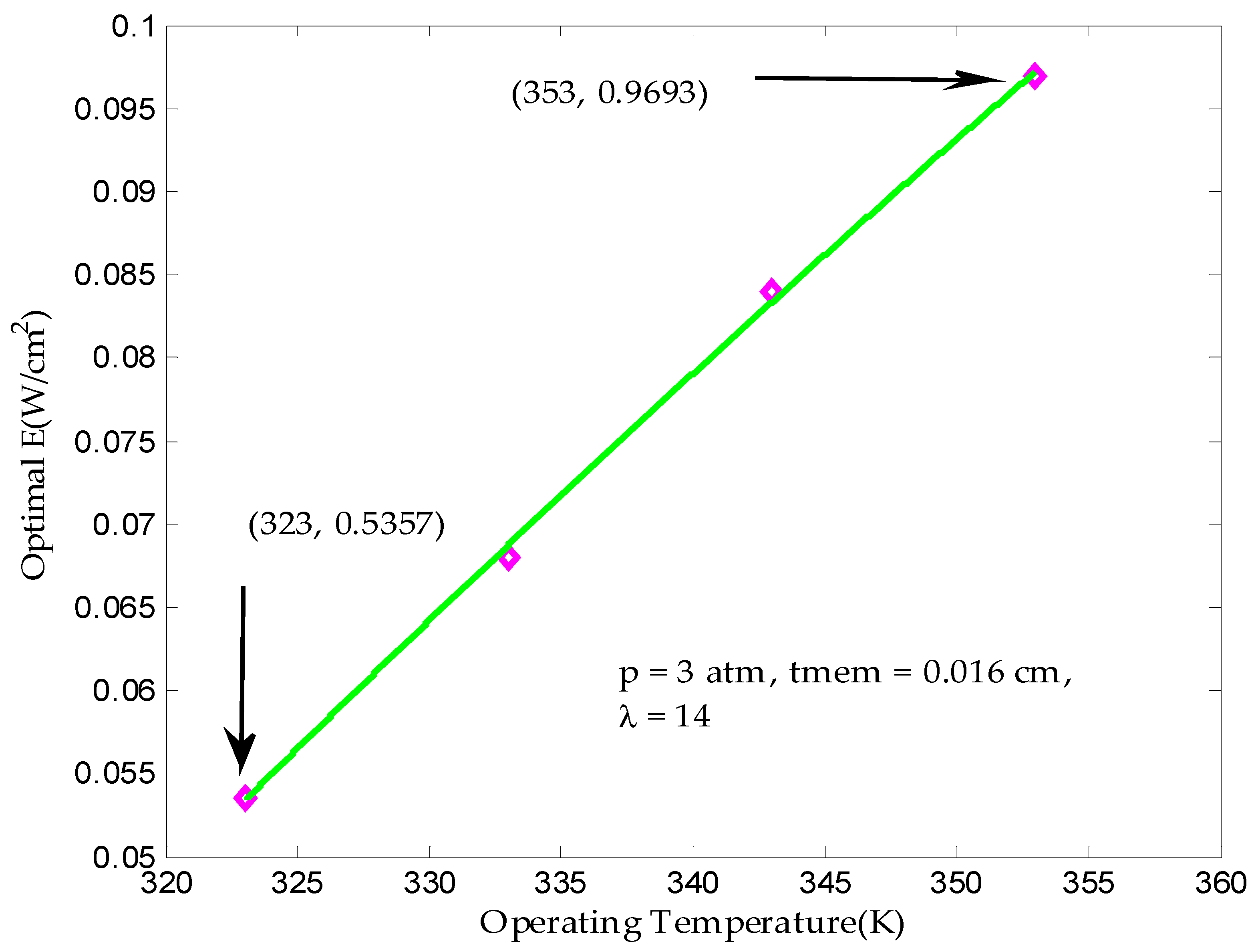
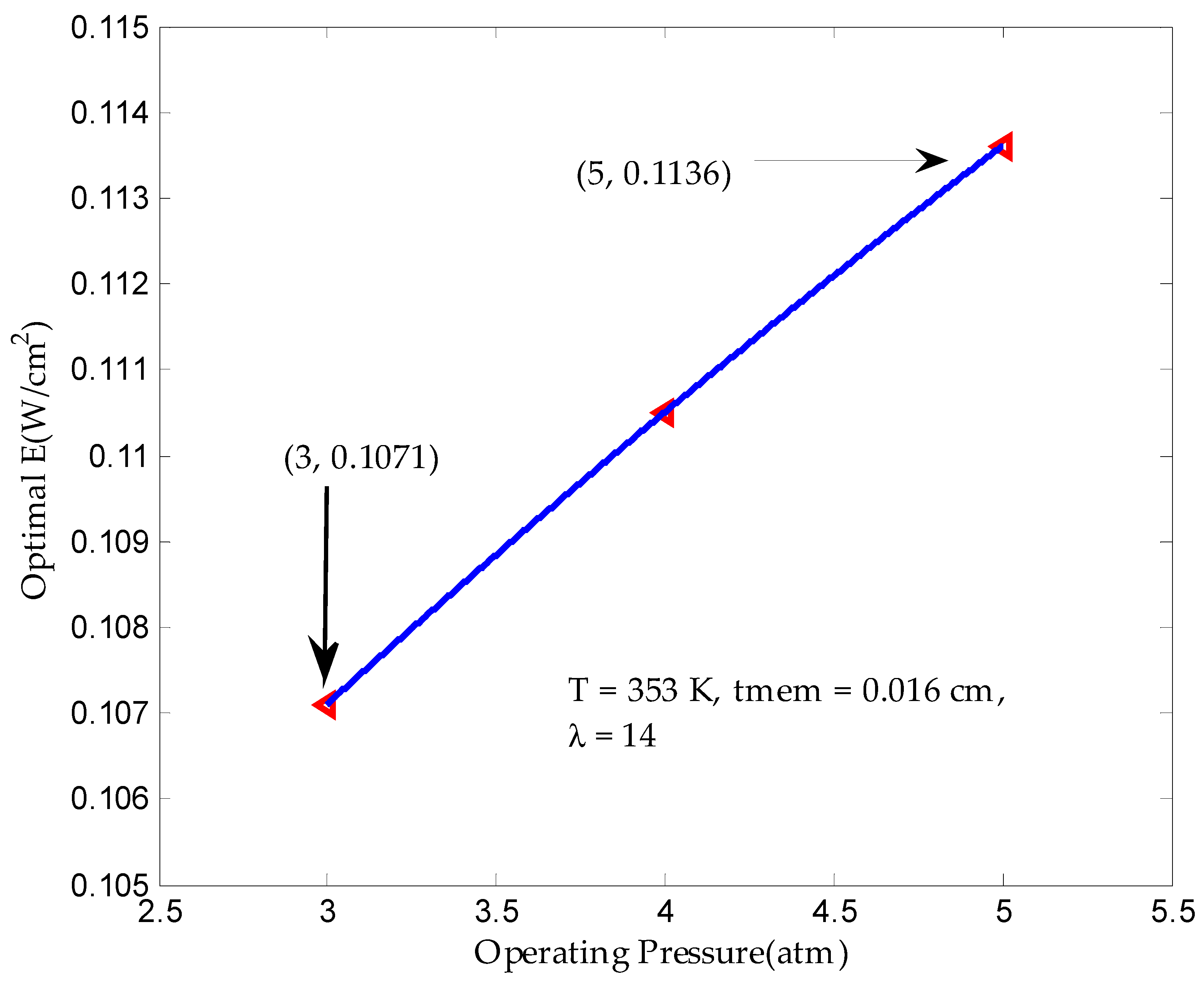
3.1. Maximum Output Power Density in Finite Time

In the finite time working process of the irreversible PEMFC, the output power density keeps going with the work, that is, as the current density increases, it increases first and then decreases. Therefore, during the finite time working of the irreversible PEMFC, it must be there is a current density that maximizes the output power density of the irreversible PEMFC. At this time, the irreversible PEMFC has the lowest power dissipation and the most useful output power.
The output power density P of the irreversible PEMFC is related to the operating temperature T, the working pressure a, the proton exchange membrane water content λ and the proton membrane thickness t m e m and the current density i, which can be expressed as
P = f ( i , T , a , λ , t m e m )
When the working pressure a of the irreversible PEMFC, the water content λ of the proton exchange membrane, and the thickness t m e m of the proton exchange membrane are kept constant, the output power density is only related to the current density i and the operating temperature T , which can be expressed as
P * = g ( i , T )
When the operating temperature of the irreversible PEMFC is T 1 , then the output power density of the irreversible PEMFC is only related to the current density, which can be expressed as
P 1 = h ( i )
In Equations (1)–(30), the output power P 1 is a constrained composite function with respect to the current density i , and the maximum output power density P max 1 can be obtained. When the operating temperature of the irreversible PEMFC is T 2 , the output power density is a constrained composite function with respect to the current density, and the maximum output power density P max 2 can be obtained. By analogy, when the operating temperature of the irreversible PEMFC is Tn, the maximum output power density is obtained as Pn, so that the maximum output power density of the irreversible PEMFC in a finite time can be obtained as a function of the operating temperature of the PEMFC. Similarly, the effect of the operating pressure of the irreversible PEMFC, the water content of the proton exchange membrane, and the thickness of the proton exchange membrane on its optimal output power density can also be studied.
Figure 3 reflects the maximum output power density of the irreversible PEMFC as a function of operating temperature. It can be seen from the figure that the maximum output power density of the irreversible PEMFC increases with the increase of the operating temperature in a finite time. Mainly due to the increase of temperature, the exchange current density can be increased, the activation overpotential is reduced, and the proton pass rate can be increased, so that the Ohmic overpotential is reduced, and the power dissipation caused by the activation overpotential and the Ohmic overpotential is reduced. When the power dissipation is small, the minimum entropy production decreases, and the maximum output power increases. When the operating temperature is 323 K, the corresponding optimal output power density is 0.4765 W/cm2; when the operating temperature is 353 K, the corresponding optimal output power density is 0.5539 W/cm2. This shows that increasing the operating temperature of the PEMFC from 50 °C to 80 °C can increase the optimal output power density by 16% for a finite time. From the results obtained, increasing the operating temperature of the PEMFC can effectively improve its optimal output power density in a suitable working range.
Figure 4 shows that increasing the operating pressure can increase the optimal output power density of the irreversible PEMFC. The increase of the operating pressure causes the exchange current density to increase, the activation overpotential decreases, and the reversible potential increases. Then the irreversibility of the irreversible PEMFC is weakened, the reversibility is enhanced, the minimum entropy production is reduced, and the maximum output power density is increased. When the working pressure is 3 atm, the corresponding optimal output power density is 0.4629 W/cm2; when the working pressure is 5 atm, the corresponding optimal output power density is 0.5161 W/cm2. From the numerical value of increase, the working pressure of PEMFC is increased from 3 atm to 5 atm, and the optimal output power density is increased by 11.5%. This shows that the irreversible PEMFC can further improve its optimal output power density by appropriately increasing its operating pressure during finite time operation.
It is known from Figure 5 that the maximum output power density decreases as the proton film thickness increases. Increasing the thickness of the proton exchange membrane increases the hindrance of ions through the proton exchange membrane. At the same time, the Ohmic loss is increased, the output power density is reduced, and the maximum output power is correspondingly reduced. When the proton exchange membrane thickness is 0.012 cm, the corresponding optimal output power density is 0.5139 W/cm2; when the proton exchange membrane thickness is 0.020 cm, the corresponding optimal output power density is 0.425 W/cm2. This shows that when the proton film thickness is reduced from 0.020 cm to 0.012 cm, the optimal output power density is increased by 21%. From the data point of view, reducing the thickness of the proton exchange membrane can increase the optimal output power density of the PEMFC in a finite time, but the thickness of the proton membrane should not be too thin to avoid needle punching or cracking, and reduce the performance of the PEMFC.
As can be seen from Figure 6, increasing the water content of the proton membrane can improve the performance of the irreversible PEMFC and further improve the optimal output power density. When the membrane water content λ = 7, the optimal output power density is only 0.2973 W/cm2, which indicates that the performance of PEMFC is seriously degraded when the water content of the membrane is too small; when the membrane water content λ = 23, that is, the water content of the proton membrane reaches saturation state, The optimal output power density is only 0.4711 W/cm2. The optimal output power density of the PEMFC increased by 58% when the water content of the proton exchange membrane increased from 50% to saturation. Controlling the water content of the proton exchange membrane between the ideal state and the saturated state at any time can effectively improve the optimal output power density of the irreversible PEMFC.

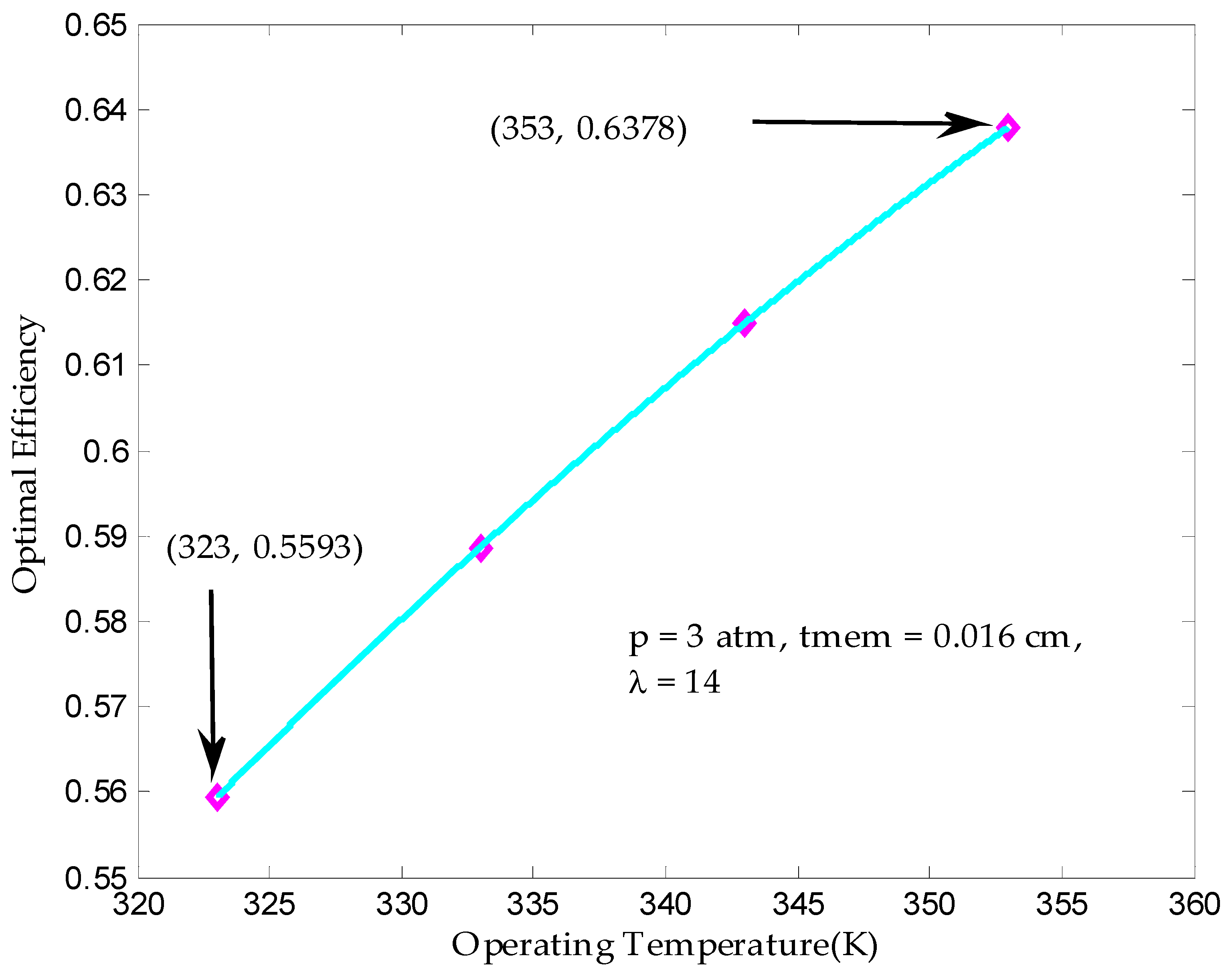
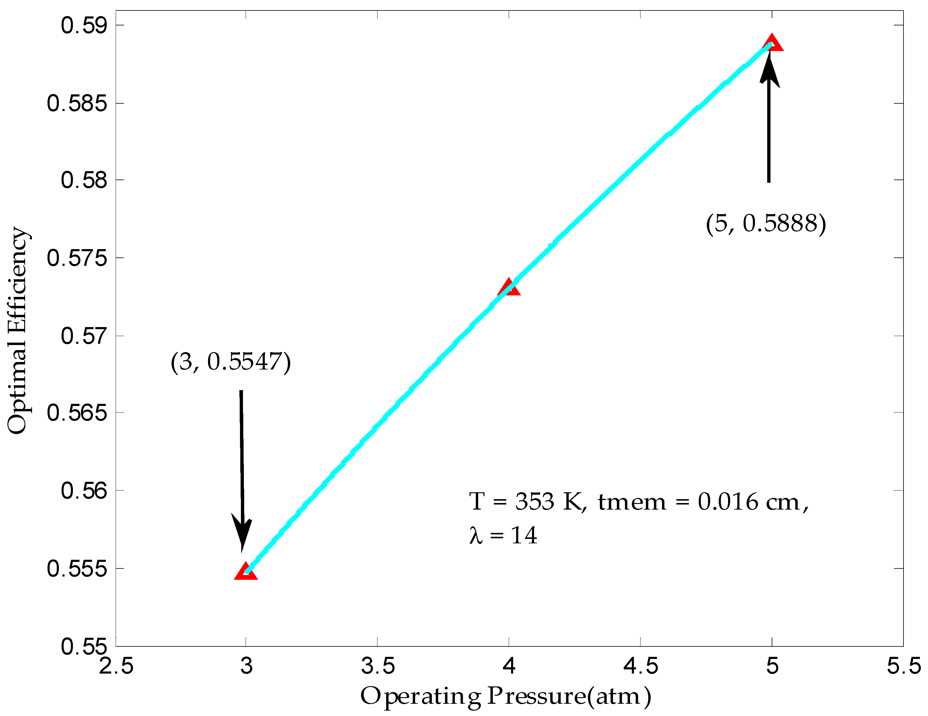
3.2. Maximum Output Efficiency

In a working process of an irreversible PEMFC, the output efficiency is not constant, but as the operating current of the PEMFC increases, it first increases and then decreases, and the maximum output efficiency is obtained in the low current region. Therefore, there must be such a moment in the finite time working process of the irreversible PEMFC to make the PEMFC output efficiency optimal. Studying the influence of controllable factors and uncontrollable factors of irreversible PEMFC on the optimal output efficiency can further improve the performance of PEMFC and have certain guiding significance for practical engineering operations. Based on the finite time thermodynamics theory, the specific research method of optimal output efficiency is similar to the research method of optimal output power density.
Increasing the operating temperature increases the optimal output efficiency of the irreversible PEMFC during finite hours of operation. Figure 7 shows that when the operating temperature is 323 K, the corresponding optimal output efficiency is 0.5593; when the operating temperature is 353 K, the corresponding optimal output efficiency is 0.6339. This shows that increasing the operating temperature of the PEMFC from 50 °C to 80 °C can increase the optimal output efficiency by 13% for a finite time. The increase in temperature of PEMFC accelerates the passage rate of protons, the conductivity of proton exchange membrane increases, the power generation of PEMFC increases, and the output efficiency increases. Properly increasing the operating temperature during the finite time operation of the irreversible PEMFC can further improve the optimal output efficiency.
As can be seen from Figure 8, increasing the working pressure can improve the optimal output efficiency of PEMFC in a finite time. When the working pressure is 3 atm, the corresponding optimal output efficiency is 0.5547; when the working pressure is 5 atm, the corresponding optimal output efficiency is 0.5588. It can be seen from the value of the cluster that the operating pressure of the PEMFC has almost no effect on the optimal efficiency of the irreversible PEMFC. Similarly, for the effect of the proton film thickness on the optimal efficiency in Figure 9, when the proton exchange membrane thickness is 0.012 cm, the corresponding optimal output efficiency is 0.5583; when the proton exchange membrane thickness is 0.020 cm, the corresponding optimal output efficiency is 0.5572. This indicates that the proton film thickness has little effect on the optimal output efficiency.
As can be seen from Figure 10, when the water content of the proton membrane is λ = 7 , that is, the water content of the proton membrane is only 50%, the optimal output power density is 0.5496; when the water content of the proton membrane is λ = 23 , the water content of the proton membrane is saturated. The optimal output efficiency of PEMFC is 0.5583. The proton membrane water content increased from only 50% to saturation, and the maximum output efficiency of the irreversible PEMFC increased by 1.6%, indicating that the proton membrane water content has almost no effect on the optimal output efficiency.

3.3. Maximum Ecological Objective Function in Finite Time

From the ecological performance curve of irreversible PEMFC, we can know that its ecological objective function increases first and then decreases with the continuous work of PEMFC. It shows that the ecological objective function of PEMFC is not a single change, but the difference between output power density and power dissipation must be the largest, that is, the ecological objective function is the largest. It is necessary to explore the influence of the controllable factors and uncontrollable factors of the irreversible PEMFC on the maximum ecological objective function, so that the output power can be further improved, and at the same time, the entropy production can be reduced, thereby reducing the power dissipation. Based on the finite time thermodynamics theory, the method used is similar to the method of obtaining the maximum output power density.
Figure 11 reflects the change in the maximum ecological objective function as the operating temperature of the PEMFC changes. It can be seen from the figure that the maximum ecological objective function of the irreversible PEMFC in a finite time increases as the operating temperature rises. Because increasing the operating temperature can increase the exchange current density, reduce the activation loss, reduce the internal resistance caused by the activation overpotential, reduce the entropy production, reduce the power dissipation, reduce the irreversibility, increase the output power, and output power. The difference from the power dissipation increases, that is, the ecological objective function increases. When the operating temperature is 323 K, the corresponding maximum ecological objective function is 0.05357; when the working temperature is 353 K, the corresponding maximum ecological objective function is 0.09693. This shows that increasing the operating temperature of the PEMFC from 50 °C to 80 °C can increase the maximum ecological objective function by 81% for a finite time.
It can be seen from Figure 12 that increasing the operating pressure of PEMFC can increase the maximum ecological objective function of PEMFC during finite time work, because increasing the operating pressure can increase the reversible electromotive force, reduce the irreversible loss, and output power. Increase, power dissipation decreases, and the irreversible PEMFC ecological objective function increases. When the working pressure is 3 atm, the maximum ecological objective function of PEMFC is 0.1071; when the working pressure is 5 atm, the corresponding maximum ecological objective function is 0.1135. From the numerical value of the increase, the working pressure is increased from 3 atm to 5 atm, and the optimal ecological objective function is increased by 6%. From the numerical values, the impact of the operating pressure on the maximum ecological objective function is not obvious.
Figure 13 shows that the maximum ecological objective function of PEMFC decreases as the proton film thickness increases. Increasing the thickness of the proton exchange membrane, the increase of ions through the proton exchange membrane increases, the Ohmic loss is increased, the power dissipation is increased, the output power is reduced, and the difference between the output power and the power dissipation is reduced, that is, the ecological criterion function is reduced. When the film thickness is 0.012 cm, the corresponding optimal ecological objective function is 0.1071; when the film thickness is 0.020 cm, the corresponding optimal ecological objective function is 0.0962. This shows that when the proton membrane thickness is reduced from 0.020 cm to 0.012 cm, the optimal ecological objective function is increased by 11%.
The proton membrane water content has a very important influence on the optimal performance of PEMFC. It is known from Figure 14 that as the water content of the membrane increases, the optimal ecological objective function of PEMFC is increased. The increase of membrane water content can increase the pass rate of protons and accelerate the electrochemical reaction. When weakened, the power dissipation becomes smaller and the maximum ecological objective function increases. When the water content of the proton membrane, that is, the water content of the proton membrane is only 50%, the maximum ecological objective function is 0.0733; when the membrane water content, that is, the water content of the proton membrane reaches saturation, the maximum ecological objective function is 0.1071. The optimal ecological objective function of PEMFC increased by 46% when the water content of the proton exchange membrane increased from 50% to saturation. Controlling the water content of the proton membrane in an ideal state and saturation state can improve the optimal ecological objective function of the irreversible PEMFC.

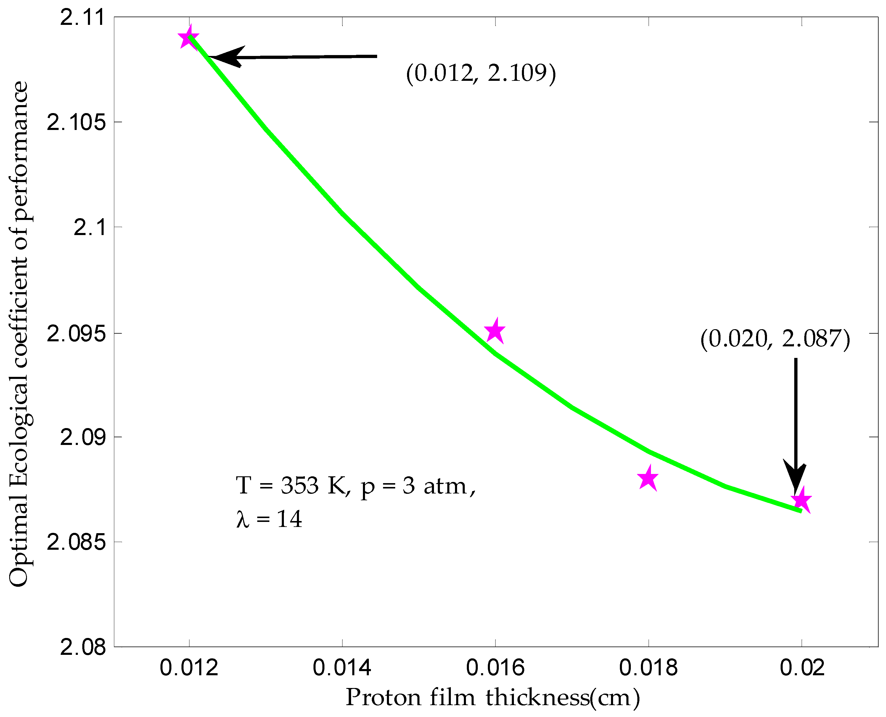
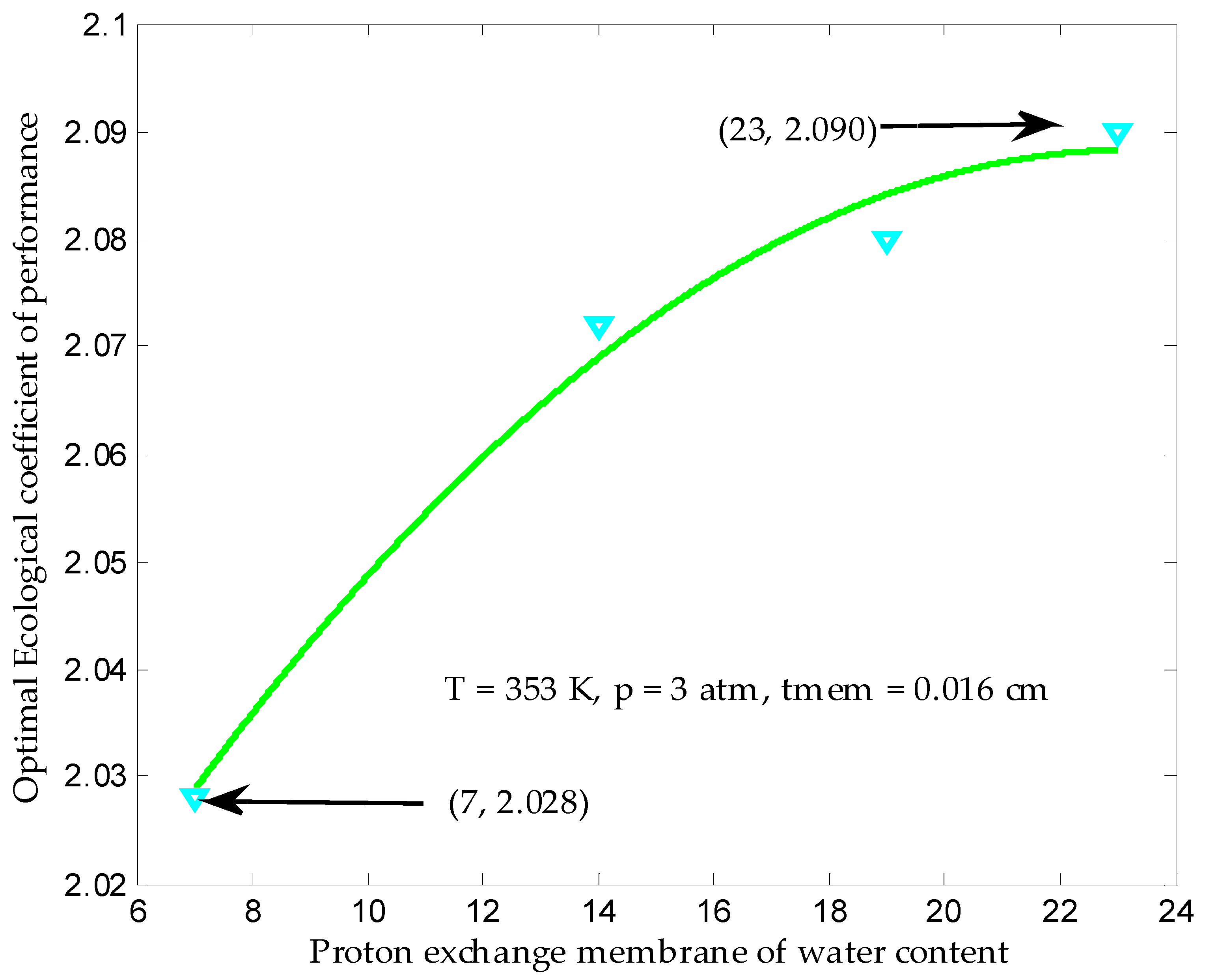
3.4. Maximum Ecological Performance Coefficient

The working temperature of the PEMFC has a certain influence on its ecological performance. It can be seen from Figure 15 that increasing the operating temperature can increase the maximum ecological performance coefficient during the operation process of the PEMFC. This is mainly because raising the working temperature of PEMFC can reduce the irreversible loss caused by the activation overpotential, the power dissipation is reduced, the output power is increased, and the ratio of output power to power dissipation is increased, that is, the ecological performance coefficient is changed. Large, optimal ecological performance coefficients also increase. When the working temperature of PEMFC is 323 K, the corresponding maximum ecological performance coefficient is 1.807; when the working temperature is 353 K, the corresponding maximum ecological performance coefficient is 2.419. This shows that increasing the operating temperature of PEMFC from 50 °C to 80 °C can increase the optimal ecological performance coefficient of irreversible PEMFC by 34% in a finite time.
The operating pressure of PEMFC has an important influence on its performance. Figure 16 shows that increasing the operating pressure can increase the optimal ecological performance coefficient of irreversible PEMFC. When the working pressure is 3 atm, the maximum ecological performance coefficient is 2.109; when the working pressure is 5 atm, the corresponding maximum ecological performance coefficient is 2.219. From the numerical value of increase, the working pressure of the PEMFC is increased from 3 atm to 5 atm, and the optimal ecological performance coefficient is increased by 8%. From the numerical values, the operating pressure has a certain influence on the improvement of the maximum ecological performance coefficient, but it has much less influence on the optimal ecological performance coefficient than the operating temperature.
Figure 17 shows that the maximum ecological performance coefficient of an irreversible PEMFC changes with the change in proton film thickness. Increasing the thickness of the proton exchange membrane increases the barrier of ions through the proton exchange membrane, increases the Ohmic loss, increases the power dissipation, reduces the output power, and reduces the ratio of output power to power dissipation, the ecological coefficient of performance decreases. When the proton exchange membrane thickness is 0.012 cm, the corresponding maximum ecological performance coefficient is 2.109; when the proton exchange membrane thickness is 0.020 cm, the corresponding maximum ecological performance coefficient is 2.087. This shows that the effect of operating pressure on the optimal ecological performance coefficient of the irreversible PEMFC during finite time work is very small.
It can be seen from Figure 18 that the maximum ecological performance coefficient of the irreversible PEMFC varies with the change of the water content of the proton exchange membrane. One can see that the water content of the proton exchange membrane does not have much influence on the maximum ecological performance coefficient of the irreversible PEMFC.

4. Conclusions

After considering the effects of polarization losses and leakage current, a finite time thermodynamic model of PEMFC for vehicle use was established. Effects of operating parameters, including operating temperature, operating pressure, proton exchange membrane water content and proton exchange membrane thickness, on the optimal performance of the irreversible PEMFC were numerically studied in detail.
When the operating temperature of the irreversible PEMFC increases from 50 °C to 80 °C, the optimal output power density increases by 16%, the maximum output efficiency increases by 13%, the maximum ecological criterion function increases by 81%, and the optimal ecological performance coefficient increases by 34%. The proton film thickness has little effect on the output efficiency and the ecological of coefficient performance. The maximum output power density increased by 58% as the water content of the proton exchange membrane increased from 50% to the saturation point. The maximum output power density increases with the operating pressure.
Based on thermodynamic optimization and analysis, improving the operating temperature and working pressure, increasing the membrane water content and reducing the film thickness can further improve the optimal performance of the irreversible PEMFC.

Author Contributions

All of the authors contributed to publishing this article. The collection of materials and summarization of this article was done by C.L. and Y.L. The coding and programming works was done by C.L. and B.X. The conceptual ideas, methodology and guidance for the research were provided by Z.M.

Funding

We gratefully acknowledge the financial support of the National Natural Science Foundation of China (No. 51306079 and 51176069), the Jiangsu Provincial Key Research Funding (No. BE2017008) and Scientific Research Foundation of Nanjing Forestry University (No. GXL2018004).

Conflicts of Interest

The authors declare no conflicts of interest.

References

  1. Yuan, D.Q. The analytical method of finite time thermodynamics about the physical and the chemical performances of the fuel cell. Chin. J. Chem. Phys. 1999, 12, 63–66. [Google Scholar]
  2. Yan, Z.J. Comment on: The analytical method of finite time thermodynamics about the physical and the chemical performances of the fuel cell. Chin. J. Chem. Phys. 2001, 14, 378–380. [Google Scholar]
  3. Yuan, D.Q. Reply to Comment on: The analytical method of finite time thermodynamics about the physical and the chemical performances of the fuel cell. Chin. J. Chem. Phys. 2001, 14, 381–383. [Google Scholar]
  4. Yin, S.L. Ecological Optimization for a Hybrid System Integrating a Phosphoric Acid Fuel Cell with An Absorption Refrigerator. Master’s Thesis, Donghua University, Shanghai, China, 2017. [Google Scholar]
  5. Wei, F.F. The Optimal Thermodynamic Research and Application of Proton Exchange Membrane Fuel Cells. Master’s Thesis, Donghua University, Shanghai, China, 2013. [Google Scholar]
  6. Zhang, S.; Qian, X.R.; Shi, B. Multi-objective optimization for PEM fuel cell system. Comput. Appl. Chem. 2018, 35, 37–44. [Google Scholar]
  7. Xue, D.; Dong, Z. Optimal fuel cell system design considering functional performance and production costs. J. Power Sources 1998, 76, 69–80. [Google Scholar] [CrossRef]
  8. Frangopoulos, C.A.; Nakos, L.G. Development of a model for thermoeconomic design and operation optimization of a PEM fuel cell system. Energy 2006, 31, 1501–1519. [Google Scholar] [CrossRef]
  9. Me, M.; Sedighi, K.; Amidpour, M.; Alizadeh, E.; Miansari, M. Experimental and thermodynamic approach on proton exchange membrane fuel cell performance. J. Power Sources 2009, 190, 356–361. [Google Scholar]
  10. Tohidi, M.; Mansouri, S.H.; Amiri, H. Effect of primary parameters on the performance of PEM fuel cell. Int. J. Hydrogen Energy 2010, 17, 9338–9348. [Google Scholar] [CrossRef]
  11. Wei, F.F.; Huang, Y.W. Performance characteristics of an irreversible Proton Exchange Membrane (PEM) Fuel Cell. J. Donghua Univ. 2012, 29, 393–398. [Google Scholar]
  12. Springer, T.E.; Zawodzinski, T.A.; Gottesfeld, S. Polymer electrolyte fuel cell model. J. Electrochem. Soc. 1991, 138, 2334–2342. [Google Scholar] [CrossRef]
  13. Ahmed, F.; Hegazy, R. Multi-verse optimizer for identifying the optimal parameters of PEMFC. Energy 2018, 143, 634–644. [Google Scholar]
  14. Andreadis, G.M.; Podias, A.K.; Tsiakaras, P.E. The Effect of the Parasitic Current on the Direct Ethanol PEM Fuel Cell Operation. J. Power Sources 2008, 181, 214–227. [Google Scholar] [CrossRef]
  15. Zhao, Y.R.; Ou, C.J.; Chen, J.C. A new analytical approach to model and evaluate the performance of a class of irreversible fuel cells. Int. J. Hydrogen Energy 2011, 36, 15304–15312. [Google Scholar] [CrossRef]
  16. Yoon, K.J.; Gopalan, S.; Pal, U.B. Effect of Fuel Composition on Performance of Single-Step Cofired SOFCs. J. Electrochem. Soc. 2007, 154, 1080–1087. [Google Scholar] [CrossRef]
  17. Hamid, K.E. Temperature Effect on Proton Exchange Membrane Fuel Cell Performance Part I: Modelling and Validation. Energy Procedia 2014, 61, 2613–2616. [Google Scholar] [Green Version]
  18. Calise, F. Simulation and exergy analysis of a hybrid Solid Oxide Fuel Cell (SOFC)–Gas Turbine System. Energy 2006, 31, 3278–3299. [Google Scholar] [CrossRef]
  19. Chan, S.H.; Xia, Z.T. Polarization effects in electrolyte/electrode-supported solid oxide fuel cells. J. Appl. Electrochem. 2002, 32, 339–347. [Google Scholar] [CrossRef]
  20. Calise, F.; Palombo, A. Design and partial load exergy analysis of hybrid SOFC–GT power plant. J. Power Sources 2006, 158, 225–244. [Google Scholar] [CrossRef]
  21. Chan, S.H.; Khor, K.A.; Xia, Z.T. A complete polarization model of a solid oxide fuel cell and its sensitivity to the change of cell component thickness. J. Power Sources 2001, 93, 130–140. [Google Scholar] [CrossRef]
  22. Shaker, H. Analytical modeling of PEM fuel cell i-V curve. Renew. Energy 2011, 36, 451–458. [Google Scholar]
  23. Zawodzinski, T.A.; Smith, V.T.; Springer, T.A. Water uptake by and transport through Nafion 117 membranes. J. Electrochem. Soc. 1992, 140, 1041–1047. [Google Scholar] [CrossRef]
  24. Liu, H. Modeling and Simulation of Proton Exchange Membrane Fuel Cell. Master’s Thesis, School of North China Electric Power University, Beijing, China, 2012. [Google Scholar]
  25. Mann, R.F.; Hooper, M.; Jensen, H.M.; Peppley, B.A.; Roberge, P.R. Development and application of a generalized steady-state electrochemical model for a PEM fuel cell. J. Power Sources 2000, 86, 173–180. [Google Scholar] [CrossRef]
  26. Mo, Z.J. Parameter optimization for a PEMFC model with a hybrid genetic algorithm. Int. J. Energy Res. 2006, 30, 585–897. [Google Scholar] [CrossRef]
  27. Chen, X.; Li, W.B.; Gong, G.C. Parametric analysis and optimization of PEMFC system for maximum power and efficiency using MOEA/D. Appl. Therm. Eng. 2017, 121, 400–409. [Google Scholar] [CrossRef]
  28. Li, C.J.; Liu, Y.; Ma, Z.S. Thermodynamic analysis of the performance of an irreversible PEMFC. Defect Diffus. Forum 2018, 388, 350–360. [Google Scholar] [CrossRef]
  29. Barbir, F.; Gorgun, H.; Wang, X. Relationship between pressure drop and cell resistance as a diagnostic tool for PEM fuel cells. J. Power Sources 2017, 141, 96–101. [Google Scholar] [CrossRef]
  30. Santarelli, M.G.; Torchio, M.F.; Cochis, P. Parameters estimation of a PEM fuel cell polarization curve and analysis of their behavior with temperature. J. Power Sources 2006, 159, 824–835. [Google Scholar] [CrossRef]
  31. Angulo-Brown, F. An ecological optimization criterion for finite time heat engines. J. Appl. Phys. 1991, 69, 7465. [Google Scholar] [CrossRef]
  32. Chen, L.; Sun, F.; Chen, W. On the ecological figures of merits for thermodynamic cycles. J. Eng. Therm. Energy Power 1994, 9, 374–376. [Google Scholar]
  33. Yasin, U.; Bahri, S.; Ali, K. Performance analysis and optimization of an irreversible dual-cycle based on an ecological coefficient of performance criterion. Appl. Energy 2005, 82, 23–29. [Google Scholar]
  34. Khalil, B.; Ali, C. Analysis of proton exchange membrane fuel cells voltage drops for different operating parameters. Int. J. Hydrogen Energy 2018, 43, 3512–3519. [Google Scholar]
  35. Berning, T.; Djilali, N. Three-dimensional computational analysis of transport phenomena in a PEM fuel cell—A parametric study. J. Power Sources 2003, 124, 440–452. [Google Scholar] [CrossRef]
  36. Ay, M.; Midilli, A.; Dincer, I. Thermodynamic modeling of a proton exchange membrane fuel cell. Int. J. Energy 2006, 3, 16–44. [Google Scholar]
  37. Rowe, A.; Li, X.G. Mathematical modeling of proton exchange membrane fuel cells. J. Power Sources 2001, 102, 82–96. [Google Scholar] [CrossRef] [Green Version]
Figure 1. The working principle of PEMFC.
Processes 07 00419 g001
Figure 2. Relationship between leakage current density and operating temperature.
Processes 07 00419 g002
Figure 3. Optimal output power density varying with operating temperature.
Processes 07 00419 g003
Figure 4. Optimal output power density varying with operating pressure.
Processes 07 00419 g004
Figure 5. Optimal output power density varying with membrane thickness.
Processes 07 00419 g005
Figure 6. Optimal output power density varying with membrane water content.
Processes 07 00419 g006
Figure 7. Effect of operating temperature on optimal output efficiency.
Processes 07 00419 g007
Figure 8. Optimal output efficiency varying with operating pressure.
Processes 07 00419 g008
Figure 9. Optimal output efficiency varying with membrane thickness.
Processes 07 00419 g009
Figure 10. Effect of membrane water content on optimal output efficiency.
Processes 07 00419 g010
Figure 11. Optimal ecological objective function varying with operating temperature.
Processes 07 00419 g011
Figure 12. Optimal ecological objective function varying with operating pressure.
Processes 07 00419 g012
Figure 13. Optimal ecological objective function varying with membrane thickness.
Processes 07 00419 g013
Figure 14. Optimal ecological objective function varying with membrane water content.
Processes 07 00419 g014
Figure 15. Optimal ECOP varying with operating temperature.
Processes 07 00419 g015
Figure 16. Optimal ECOP varying with operating pressure.
Processes 07 00419 g016
Figure 17. Optimal ECOP varying with membrane thickness.
Processes 07 00419 g017
Figure 18. Optimal ECOP varying with membrane water content.
Processes 07 00419 g018
Table 1. Model parameters of irreversible PEMFC.
ParametersValues
Operating temperature, T (K)323–353
Operating pressure, a (atm)3–5
Faraday constant, F (C/mol)96485
Gas constant, R (J/mol.K)8.314
Current density, I (A/cm2)0–1.4
Proton film thickness, tmem (cm)0.012–0.020
Limit current density, iL (A/cm2)1.4
Standard mole, ΔS (J/mol)−163.4
Standard Gibbs free energy, Δg (KJ/mol)−273.3
Ambient temperature, T0 (K)298.15
Transfer coefficient, α0.5
Electronic number, n2
Resistance generated by electron flow, Rele (Ω)0.005
Proton membrane water content, λ7, 14, 19, 23
Oxygen to nitrogen molar ratio0.21/0.79

