Article

Innovative Effluent Capture and Evacuation Device that Increases COD Removal Efficiency in Subsurface Flow Wetlands

by
Pedro Cisterna-Osorio
*,
Verónica Lazcano-Castro
,
Gisela Silva-Vasquez
,
Mauricio Llanos-Baeza
and
Ignacio Fuentes-Ortega
Department of Civil and Environmental Engineering, University of Bío Bío, Concepción 378000, Chile
*
Author to whom correspondence should be addressed.
Processes 2019, 7(7), 418; https://doi.org/10.3390/pr7070418
Submission received: 9 April 2019 / Revised: 4 June 2019 / Accepted: 4 June 2019 / Published: 3 July 2019
(This article belongs to the Special Issue Wastewater Treatment Processes)

Abstract

:
The objective of this work is to evaluate the impact of innovative modifications made to conventional effluent capture and discharge devices used in subsurface flow wetlands (SSFW). The main modifications that have been developed extend the influence of the capture and discharge device in such a way that the SSFW width and height are fully covered. This improved innovative device was applied and evaluated in two subsurface flow wetlands, one on a pilot scale and one on a real scale. To evaluate the impact of the innovative device with respect to the conventional one in the operational functioning of subsurface flow wetlands, the elimination of chemical oxygen demand (COD) was measured and compared. The results show that for the innovative device, the COD removal was 10% higher than for the conventional device, confirming the validity and effectiveness of the modifications implemented in the effluent capture and discharge devices used in SSFW.

1. Introduction

Water is considered to be contaminated when its chemical, physical and biological characteristics or composition have been altered to the degree that it loses its potability for daily consumption or its adequacy for use in domestic, industrial or agricultural activities, thereby generating wastewater [1]. This statement applies regardless of whether the water is of domestic, industrial, agricultural, or rainwater origin [2].
Wastewater generated in human activities has a high load of organic material, which is measured through the chemical oxygen demand (COD). Additionally, it contains toxic substances and inorganic matter in small quantities and, as a consequence, the sum of both components pollutes water sources, undermining the sustainability of water provision and, consequently, the sustainability of humanity itself. Therefore, treatment systems including physical, chemical and biological processes have been developed and widely implemented. The objective of such processes is to reduce the load of pollutants from wastewater and, ideally, to recover, recycle and reuse them before pouring them into bodies of surface water [3].
On the other hand, it is pertinent to recover water from these liquid waste sites, a process which requires the elimination of substances that are harmful to health and the environment, which will benefit the population [4]. Efficient treatment systems have been developed for the removal of pollutants, which are also economically, technically and socially feasible. One example of these treatments is the artificial wetlands of subsuperficial flow [5]. Other authors have proposed that contaminant removal levels can be increased by modifying the design of the input geometry of a wetland, or by modifying the form of the distribution of flow and its direction within the system [6].
Artificial wetlands can efficiently reduce the biochemical oxygen demand (BOD) and total suspended solids (TSS), achieving adequate treatment levels with low energy consumption and simple and economical maintenance procedures [7]. However, the rate of organic matter biodegradation is lower, requiring typically 20 to 50 times more land area than in conventional systems [8].
In artificial wetlands, soluble organic compounds are biodegraded by aerobic processes where oxygen is supplied directly from the atmosphere by diffusion, and mainly through the process of photosynthesis, into the water column [9]. Microorganisms that are attached to the gravel, support and filtering medium in subsurface flow systems are those that biodegrade the soluble organic compounds [10]. The degradation rate is typically 10 times faster than anaerobic processes [11]. On the other hand, aerobic processes are the main mechanism to reduce soluble BOD, and the elimination of particulate BOD occurs rapidly by sedimentation and particle filtration in the spaces between gravel and roots [12].
The structural factors that affect the removal of organic matter are related to the depth of the wetland, which in turn is conditioned by the plant’s root depth, depending directly on the species of plant used. The most commonly used plant species are emergent macrophytes typical of humid areas such as the Phragmites sp. reed, bulrush (Typha sp.) or the Scirpus sp. reed [13].
These plants show great adaptation to saturated environments, fast growth, strength and resistance to climatic changes, and they also do not constitute a source of food for animals [14]. One criterion for plant selection is the adaptability to the environmental conditions where a wetland is planned to be built, and for this reason local flora species are preferred [13].
In wetlands, feeding is continuous and the water crosses horizontally. This arrangement allows contact between the residual water, the substrate and the plant’s roots with the hydraulic retention time ranging from 2 to 5 days. An impermeable barrier is considered in order to confine the wastewater and avoid groundwater contamination. This barrier is required to be resistant, smooth and protected against puncturing by sharp gravel [15]. The most frequently used waterproofing material is high-density polyethylene. Regarding the filtering substrate, it is recommended to use gravel of 10 mm to 25 mm. The diameter effect over the system can be summarized as follows: larger diameters increase water speed, whereas smaller diameters reduce the speed, causing possible floods and preferential flows [16].
The ratio (length:width) must be greater than (3:1) to approximate a piston-type flow, which is related to the slope used at the bottom of the wetland bed. [17]. The most common range for the slope is from 0.2 to 1%. [18].
In terms of modeling the system dynamics, the basic model of organic matter removal is applied in piston flow reactors [19]. This model has been validated and relates the contaminants’ removal capacity to the hydraulic residence time.
Equations:
d C a d t = K T · a
C e C o = exp ( K T · H R T )
H R T = V Q = A s · h · n Q
A S = Q · l n C o C e K T · y · n .
Table 1 defines the variables and parameters used in the sizing of subsurface flow wetlands.
In a sub-surface horizontal-flow constructed wetland (SSHFCW), design parameters, e.g., the aspect ratio (length/width), the size of the porous media, and the hydraulic loading, will determine essential features such as plug flow, dead volume and short-circuiting ratios [20]. In another work this was verified, the flow system in a pilot-scale horizontal subsurface constructed wetland was investigated. The results indicated the existence of a multiple flow system with two distinct flow paths through the gravel bed and a preferential flow at the bottom. The upper sediment indicated diffusion dominated processes due to stagnant water zones [21].
A complementary investigation studied the influence of biological growth on flow and transport patterns in horizontal subsurface flow constructed wetlands. The tanks were filled with light weight aggregates and shell sand, respectively. The obtained breakthrough curves of tracer showed that biological growth caused a pronounced reduction in drainable porosity, mainly for shell sand, whereas its effect on saturated hydraulic conductivity was negligible. The spatial distribution of the tracer after biological growth in the two-filter media showed that the flow occurred preferentially along certain paths [22].
There are similar investigations previous to the present work, that studied the issue of discharge of the effluent and even the entrance of the influent. Three different outlet flow configurations including midpoint–midpoint (X), corner–midpoint (Y) and uniform–midpoint (Z), with the same fixed inlet configurations, were studied. The mean retention time for each configuration was found to be 4.53, 3.24 and 4.65 days, respectively. According to the tracer breakthrough curve, the effective volumes for configurations X and Z were 87.5%, as compared to 62.1% for the configuration Y [23]. Other researchers expose, using inlet-outlet configurations, that forcing the flow through larger portions of the filter bed by injecting into low-conductivity layers and opposing the gravity-driven flow increased the treatment efficiency [24].
Considering the above, this work has its origin in a critical reflection upon the conventional structure and configuration of the effluent capture and evacuation device, which is located in the middle and bottom points, thereby generating preferential flows. This work shows an innovative and improved effluent capture and discharge device, patented in 2018, which modifies its structure and configuration, capturing the treated wastewater throughout the width of the wetland and the height of the water column so that it finally converges to the outlet tube.
Given the structure of the conventional device, the capture of the effluent occurs in the bottom (Figure 1A), unlike the innovative device in which the effluent flows through the entire water column (Figure 1B). The innovative device occupies a greater percentage of height than the conventional device, since water tends to flow over the entire water column and throughout the width of the wetland. Therefore, the innovative device has a greater effective volume, associated with a reduction of preferential flows.
A similar phenomenon occurs with the occupation of the wetland area, since for the innovative device the effluent is collected throughout the width of the wetland, minimizing the area lost (Figure 2).
The aim of this work is to evaluate the impact on SSFW behavior when incorporating an innovative device for the capture and exit of effluents from horizontal subsurface wetlands. This device was installed in a pilot-scale wetland and in a real-scale wetland. As a consequence, there was an increase in the efficiency of chemical oxygen demand (COD) removal from domestic wastewater, at a low cost of investment, operation and maintenance, and the system was complying with the water quality standards required by the current regulations of the country. Artificial wetlands have been validated as an alternative wastewater treatment option to the conventional systems.
The contribution of this research is that it validates and reports a new effluent capture and discharge device, which increases the efficiency of COD removal by 10% and also reduces the area and costs, further increasing the advantages of the system for socioeconomically marginal populations of Chile and the world.

2. Materials and Methods

The capture and exit device was installed in two different wetlands, the first a pilot-scale wetland, located in dependencies of the University of Bío Bío, Campus Concepción, in the city of Concepción, and the other, in the subsurface flow wetland of Recreational Center Ainahue, located in Hualqui, province of Concepción, whose coordinates are U.T.M. 686,393.79 m E; 5,905,081.35 m S (Figure 1), Chile.
(1) Pilot Wetland
Two horizontal subsurface flow wetlands of dimensions 2.0 m × 0.6 m (Table 2) were built, one of them using the proposed modifications for the innovative capture and evacuation effluent device, and the other being the conventional device. Both were connected to the same pond, which provided the synthetic wastewater. (Figure 3, Left)
(2) Real-scale Wetland
In the constructed wetland of Recreational Center Ainahue, conventional and innovative devices were used alternately to analyze the behavior of the wetland in response to them (Figure 3, Right).
The samples were taken during a period of three weeks approximately, while using the innovative device. We then proceeded to use the traditional device. During the first seven days of the operation of the device, no samples were taken so that the wetland could adapt to the change in hydrodynamics. After this pause, sampling was started for the conventional device, also for a period of three weeks. We worked with both devices in the summer at an average temperature of 23 °C.

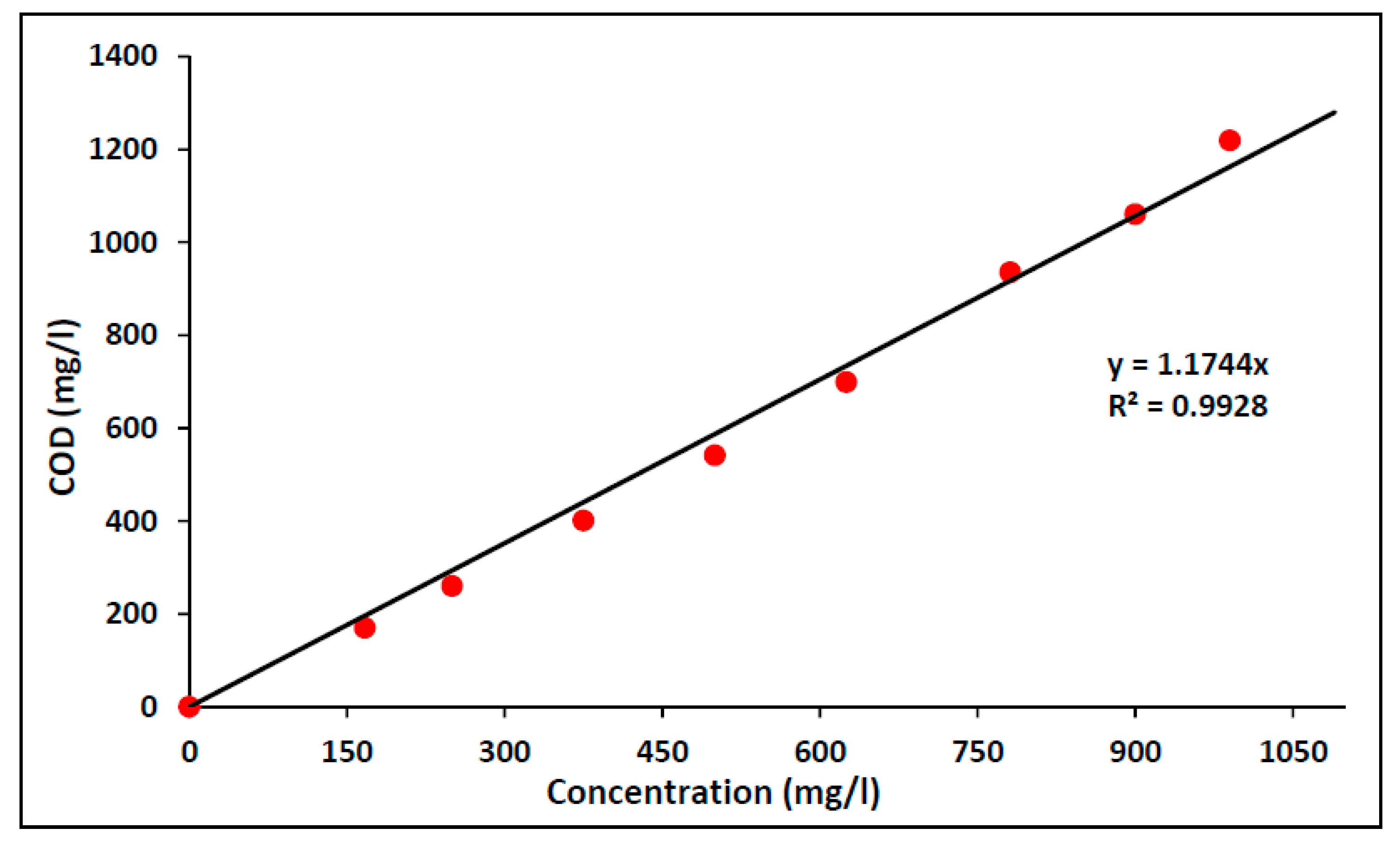
2.1. Chemical Oxygen Demand (COD)

The potassium dichromate method was used to evaluate COD levels. This method is a variation of the standard method [25], however, it maintains the basis of it. The variation used has the advantage that it requires a smaller sample and fewer reagents. The sample was chemically oxidized through the action of potassium dichromate at 150 °C for two hours. Silver sulfate was used as a catalyst and mercury sulfate was used to avoid possible interferences with chloride. Afterwards, determination by spectrophotometry at 600 nm was performed. The equipment used for the COD test: Orbeco multiparametric digital portable colorimeter (Orbeco Analytical Systems Inc., Nueva York, Nueva York, USA) and Velp Eco-25 Digestor (Velp Scientifica, Usmate, Italy).

Determination of Chemical Oxygen Demand (COD)–Substrate Relationships

Samples were composed by preparing mixtures of water and saccharose at different concentrations, and their respective COD levels were estimated. This test was performed in order to produce a calibration curve and establish the ratio of saccharose concentration/COD. It was used to calculate the saccharose mass that must be added, it allows more precision when preparing synthetic wastewater (influent).

2.2. Experimental Methodology

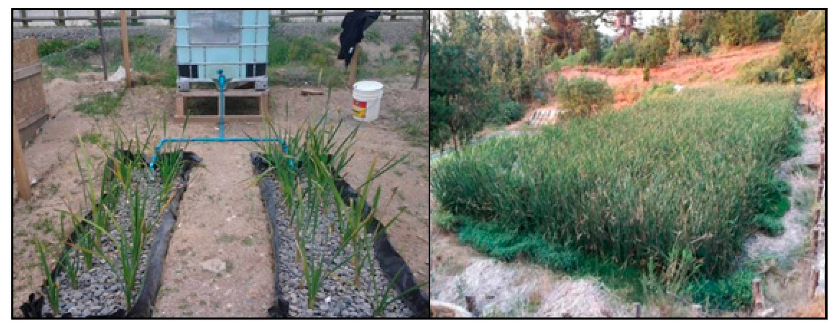
2.2.1. Pilot Wetland

a. Feed Preparation
The pilot wetland was initially fed with synthetic wastewater prepared in the laboratory according to the typical characteristics of urban wastewater [26]. This wastewater had an approximate COD of 200–300 mg/L, with the corresponding proportions of nitrogen and phosphorus in a relation of COD:N:P = 100:5:1. Approximately 200–300 mg of saccharose, 10–15 mg of phosphate hydrogen of potassium, and 50–75 mg of ammonium chloride were added per liter of water.
b. Operation Mode
The synthetic wastewater was poured into a storage pond of almost 1000 L. Process effluent was collected in a 30 L volume tank, where the samples were taken to be processed. The flow of synthetic wastewater was 2 m3/day.

2.2.2. Description of Conventional and Innovative Output Devices

Conventional Exit Device

The conventional device consisted of a PVC pipe measuring 90 mm in diameter and 13 m in length, with perforations of approximately 10 mm along its length for the capture of the effluent (Figure 4). It was located approximately 0.2 m from the bottom of the wetland. The collection of the effluent water was realized with a perforated pipe settled on the bottom of the wetland. Then, it was directed towards the exit by means of a syphon, which allowed for maintenance of the water level in the wetland.

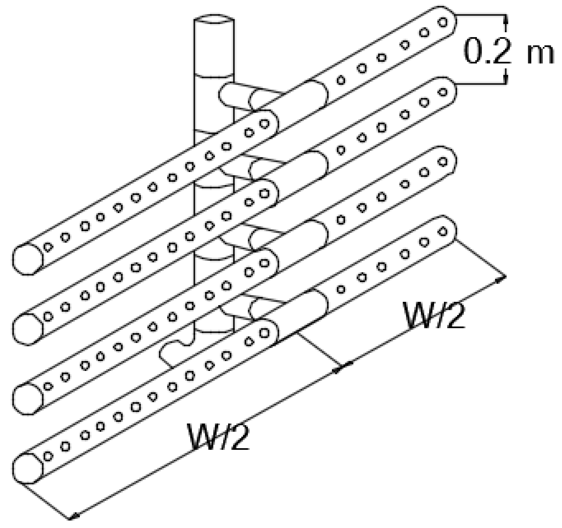
Description of the Innovative Device

The innovative exit device of the artificial wetland consisted of four sanitary PVC pipes 90 mm in diameter and 13 m long, located at different heights in climbing form at 0.15 m and 0.2 m from the bottom of the wetland, with 10 mm perforations in diameter (Figure 5).

2.2.3. Sampling and Operation of the Constructed Wetland

Effluent samples from the artificial wetland, as shown in Figure 6, were sent periodically for laboratory analysis to measure the chemical oxygen demand (COD). In parallel, the flow was estimated.

3. Results and Discussion

3.1. COD Concentration–Saccharose Relationships

From the experimental results, a straight-line regression with a slope of 1.17 was obtained, as shown in Figure 7, from which it can be stated that the saccharose had one COD per gram, which is above other organic substances [28]. The model obtained was: Y = 1.17 X, where Y is the concentration saccharose and X is the COD of saccharose. The theoretical relationship is 1.13.

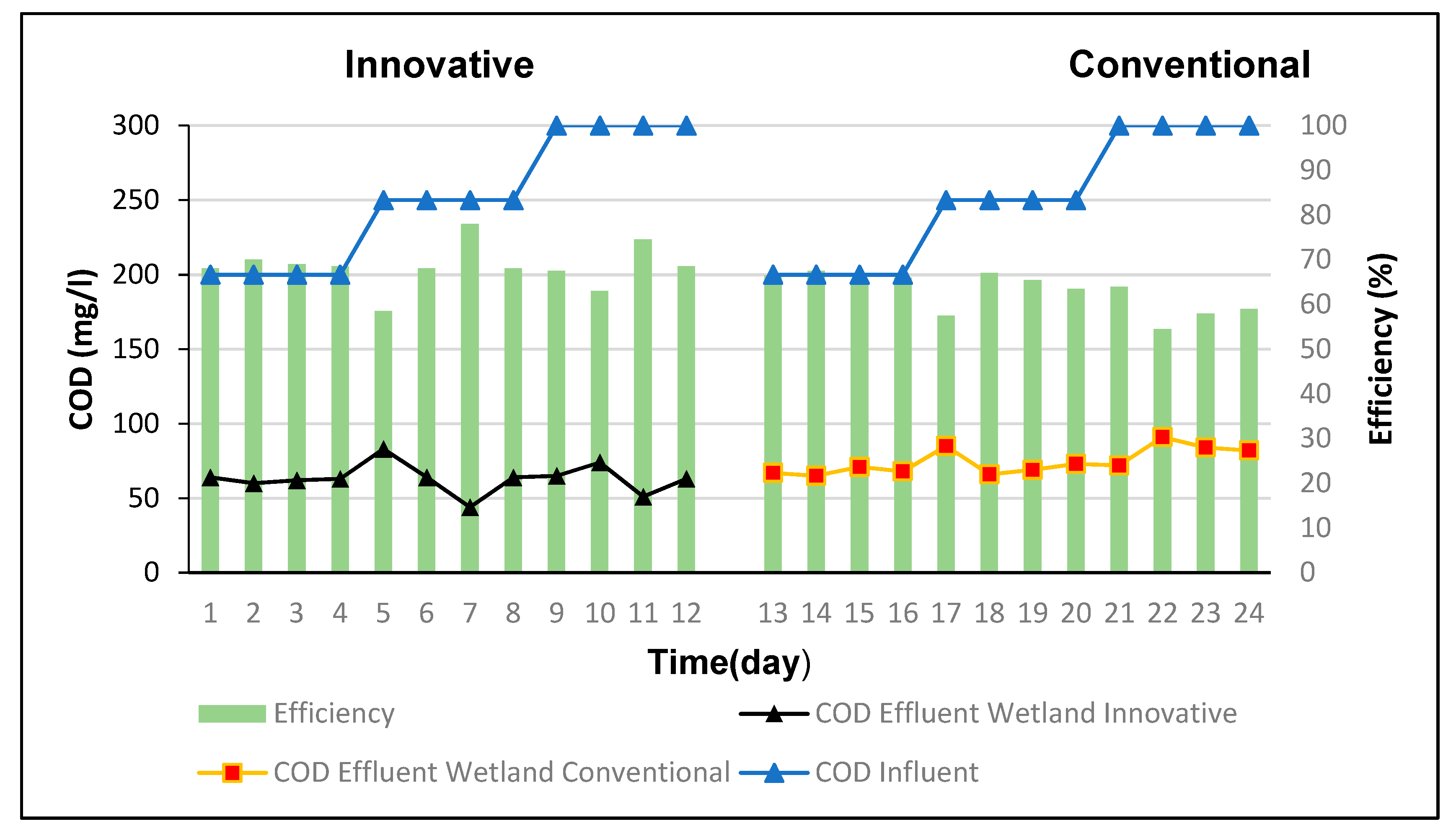
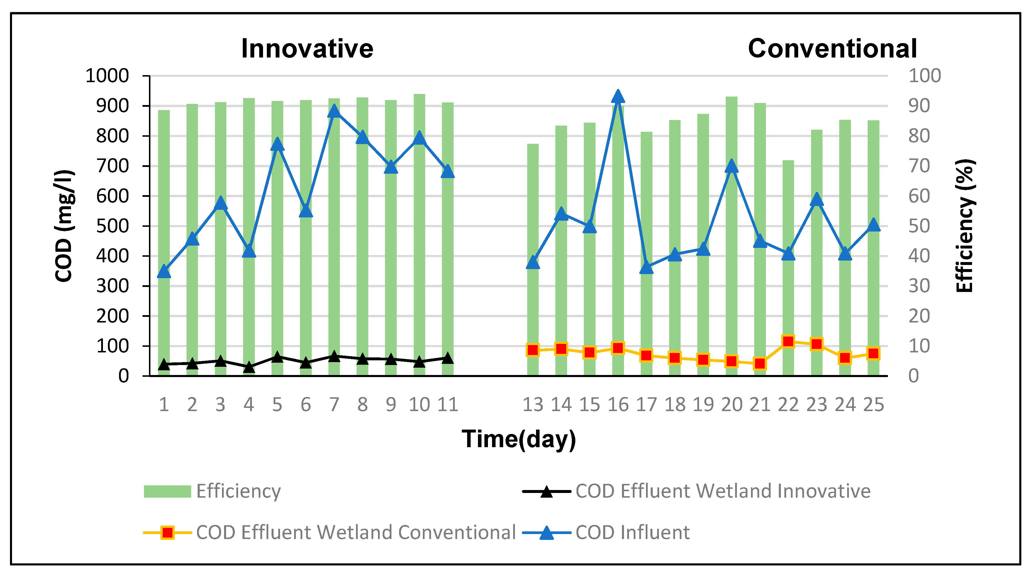
3.2. COD Concentration of the Artificial Wetland

Figure 8 and Figure 9 show the input and output concentrations of COD, using the conventional and innovative effluent capture and evacuation devices. Using the COD as an assay, we estimated the abatement efficiency that was reached in the real wetland, obtaining average efficiencies for the innovative and conventional devices of 92% and 84%, respectively, in the full-scale wetland. For the pilot wetlands, the efficiencies obtained were 69% and 63%, respectively. Therefore, a better performance is demonstrated by the use of the innovative device, since the percentage increase is 10% in both the cases of the pilot and real-scale wetlands.
The following is an overview of previous research with similar results to the pilot wetland: a nine-month campaign conducted for a horizontal subsurface flow wetland, which treated rural wastewater in the Cova Beira region. The concentrations in the influent were 506 mg/L of BOD and 677 mg/L of COD, where the average efficiencies were 83% for BOD and 68% for COD, respectively [29].
Another study examined the application of halophytic plants in a horizontal subsurface flow wetland constructed for the treatment of domestic wastewater. The pilot plant, located in Greece, was planted with a polycropping of halophytes (Tamarix parviflora, Juncus acutus, Sarcocornia perrenis and Limoniastrum monopetalum). The results show that the halophytes developed successfully in the constructed wetland, where there was an average BOD concentration of 106 mg/L in the influent; with an average elimination of approximately 63%, obtaining a removal efficiency for COD of 58% [30].
The COD elimination efficiencies of the abovementioned experiments are similar to those of the pilot wetlands that have COD elimination efficiencies of 63% with a conventional device and 69% with an innovative device. By the application of the innovative patented device, efficiencies could be improved from 68% to 75% for the Cova Beira Wetland, and from 58% to 64% for the wetland in Greece, respectively. Therefore, it is feasible to improve the efficiency of COD removal in these systems, which can be achieved by incorporating the innovative patented device.
On the other hand, there are experiments which show a high efficiency of elimination of COD. In one study, the researchers studied the percentage of removal of the organic load of wastewater from a residential building when the wastewater was treated with artificial wetlands. The sampling was carried out over 25 days in the dry season, in which the initial concentration was 164 mg/L, and after passing through the system it was 7 mg/L, indicating a 96% removal. For the rainy season, the initial concentration in the residual water was 306 mg/L and at the exit of the system it was 30 mg/L, achieving a 90% removal [31].
The study evaluated 18 artificial subsurface flow wetlands planting Stipa ichu plants. Six of the wetlands were assembled without plants and twelve of them with plants. For the construction, they used rectangular plastic containers with measurements of 13 cm in height, 33 cm in length and 26 cm in width, and with a hole in the lower part which collected the effluent. The COD removal efficiency of domestic wastewater was 92.43% for wetlands without plants and 95.5% for wetlands with plants [32]. The study evaluated two wetlands with soil biotechnology plants (SBT). Plant I was controlled for a period of 12 months and an average COD of 266 mg/L was observed in the influent, while the value of the effluent was reduced to 32 mg/L [33].
The COD elimination efficiencies of the above-mentioned experiments are similar to those of the real wetlands, which have COD elimination efficiencies of 85% with a conventional device and 92% with an innovative device. With the application of the innovative patented device, the efficiencies could be improved. The residential building and the wetland with Stipa ichu could approach 100%, while wetlands with soil biotechnology plants could improve from 87% to 95%. Therefore, it is feasible to improve the efficiency of COD removal in these systems, and this could be achieved by incorporating the innovative patented device.
For this reason, we have worked on a device that ensures the attainment of efficiency values in the high elimination range, since the previous experiments all reached very close to or over 90%. Thus, the differential shown in the quality treatment of constructed wetlands with the innovative device indicates that, with these improvements, wetlands will tend to achieve the highest values in terms of the efficiency of COD elimination.
The following experiments show the application of constructed wetlands to wastewater of different natures, aside from sewage, such as composting leachate, landfill leachate and wastewater from the pharmaceutical industry, which are more difficult to biodegrade than domestic wastewater and achieve reasonable elimination results. In Isfahan, organic matter was removed from the leachate produced in the composting facility. The study was carried out in two horizontal flow wetlands with dimensions of 1.5 m × 0.5 m × 0.5 m. One of them was planted with Vetiveria zizanioides and the other wetland remained as control, without planting. They were operated with a leachate flow rate of 24 L/d for more than five months. The control wetland eliminated 21.8% of BOD5 and 26.2% of COD and the planted wetland eliminated 74.5% of BOD5 and 53.7% of COD [34].
The removal efficiencies of two horizontal subsurface flow wetlands were also investigated by He and others, associated with the output zones of the effluent, one of downflow (F1) and the other of upflow (F2), both filled with the hybrid substrate zeolite-slag for the treatment of leachates in rural landfills. The results showed that constructed wetlands were able to eliminate the following range of COD: 20.5–48.2% (F1) and 18.6–61.2% (F2) [35].
Salazar and others, applied an artificial subsurface flow wetland for the treatment of wastewater from the cosmetic and pharmaceutical industries, using a system of rooted emergent macrophytes (Cyperus papyrus) for the removal of organic loads. The initial concentration of 92 mg/L of BOD5,20 was reduced to a concentration of 20 mg/L. The wetland showed a high efficiency in the removal of organic load, at 79% of BOD5,20 [36].
The extension of the application of wetlands to different kinds of wastewater reinforces the need to improve the efficiency of COD elimination, and therefore the need for the use of the patent innovative device in order to guarantee treatment efficiencies of 60% for all types of wastewater.

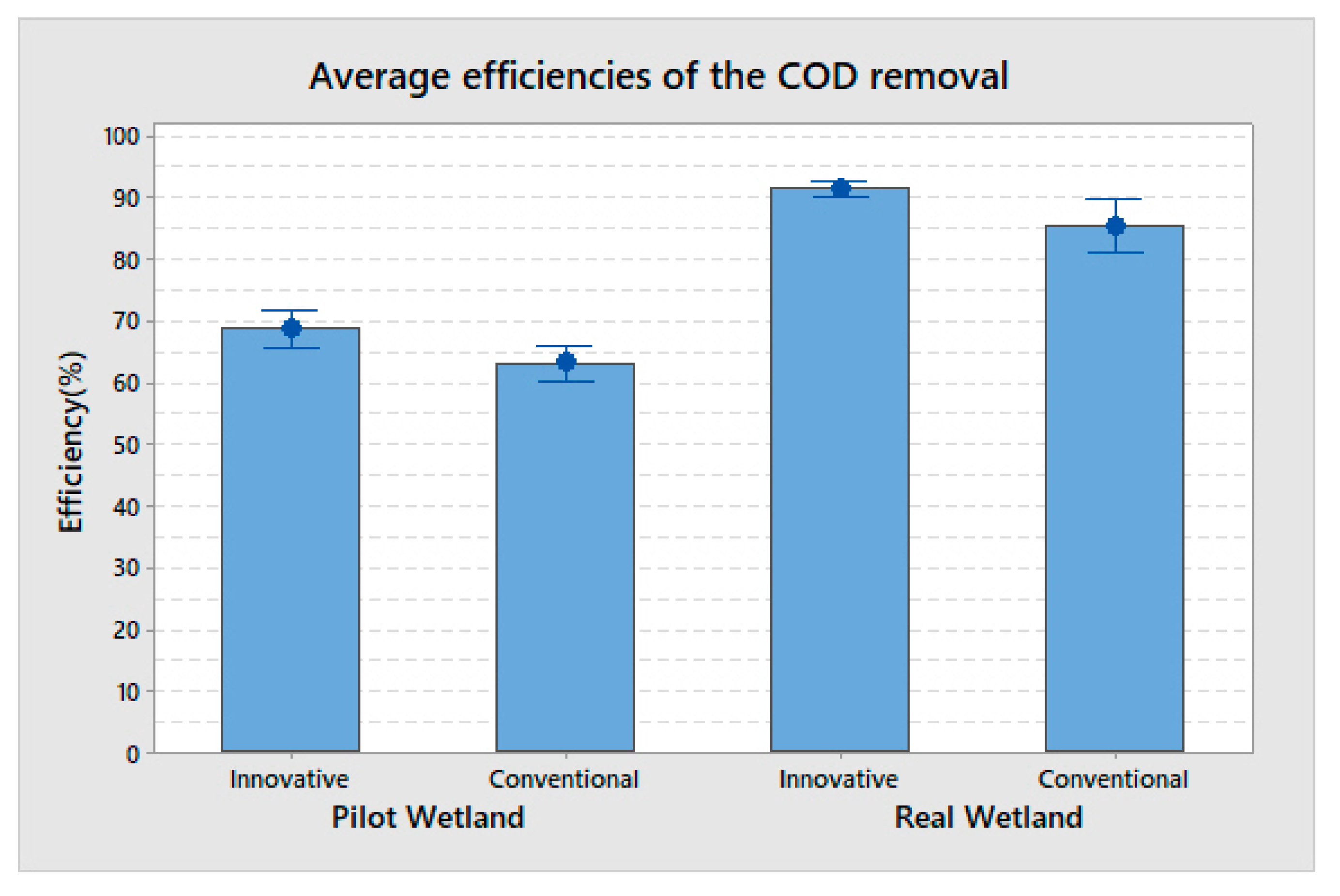
3.3. Average Efficiencies of the Removal of COD in the Wetland with Both Devices.

Figure 10 shows the efficiencies of the removal of COD in the horizontal subsurface flow wetlands during the start-up period, with the innovative and conventional devices. For each series of repeated effluent samples, the means, standard deviations and 95% confidence intervals were calculated using Minitab Inc. statistical software. These data were taken to represent average removal efficiencies and their dispersion for the different wetlands and devices, respectively. In the real wetland, the innovative device shows greater efficiency and a smaller dispersion than the conventional one (Figure 10).
Figure 10 shows that in both cases, i.e., the real and pilot wetlands, when the innovative device is used, efficiencies of COD with a better performance are obtained, exceeding the conventional device performance by 6% and 8%, respectively and in percentage terms, that is 10% for both wetlands.
These efficiencies established with the innovative device enable the obtainment of better-quality effluents with shorter residence times. Therefore, it is possible to reduce the extension of a wetland for the same treatment horizon, based on the efficiency of the innovative device being 92%, greater than the 84% efficiency for the conventional.
The lower efficiency of the conventional device is attributed to the uniqueness and location, which causes the occurrence of preferential flows, leaving a volume with very little water movement and thus generating a decrease in both the height and effective volume of the wetland.
On the other hand, with the innovative device, which possesses four equidistant catchment outlet pipes, it tends to generate a uniform flow that integrally occupies the cross-sectional area, using an effective height closer to the design height of the wetland.
When comparing the efficiencies of COD elimination, the effect of the innovative device is verified, since it evidently increases the elimination of COD.
On the other hand, a difference between the actual wetland and the pilot wetland is also observed, which is explained by the hydraulic residence times used for each experiment. In the real wetland, it is 2.8 days and the efficiency range of COD elimination is 84–92%, while in the pilot wetland it is 1.2 days with a COD elimination efficiency range of 63–69%.

4. Conclusions

It has been observed that the wetland treated with the innovative device presents higher removal efficiencies compared to those obtained with the conventional device. By obtaining higher yields, the innovative device enables the achievement of better-quality effluents, which is verified in that the performance of the innovative device has a COD removal efficiency of 92%, superior to the conventional device at 84%, for the case of the full-scale wetland.
The innovative device has a COD removal efficiency of 69%, superior to the conventional device at 63%, for the case of the pilot-scale wetland.
The innovative device achieves an efficiency of 10% higher than the conventional device in both the pilot and real wetlands.
It validates a new effluent capture and discharge device, which increases the efficiency of COD removal and also reduces the area and costs, further increasing the advantages of the SSFW for socioeconomically vulnerable populations of Chile and the world.

Author Contributions

Conceptualization, P.C.-O.; methodology, P.C.-O., V.L.-C.; software; validation, P.C.-O., G.S.-V., M.L.-B.; formal analysis, P.C.-O., V.L.-C.; investigation, P.C.-O., G.S.-V., M.L.-B., I.F.-O.; resources, P.C.-O., I.F.-O.; data curation, P.C.-O., V.L.-C.; writing—original draft preparation, P.C.-O.; writing—review and editing, P.C.-O., V.L.-C.; visualization, P.C.-O., G.S.-V., M.L.-B.; supervision, P.C.-O.; project administration, P.C.-O., I.F.-O.; funding acquisition.

Funding

This research received no external funding.

Conflicts of Interest

The authors declare no conflicts of interest.

References

  1. Rodríguez-Monroy, J.Y.; Durán de Bazúa, C. Remoción de nitrógeno en un sistema de tratamiento de aguas residuales usando humedales artificiales de flujo vertical a escala de banco. Tecnol. Cienc. Educ. 2006, 21, 25–33. [Google Scholar]
  2. Ramalho, R.S. Tratamiento de Aguas Residuales, 1st ed.; Editorial Reverte S.A.: Barcelona, Spain, 2003. [Google Scholar]
  3. Saeed, T.; Sun, G. A review on nitrogen and organics removal mechanisms in subsurface flow constructed wetlands: Dependency on environmental parameters, operating conditions and supporting media. J. Environ. Manag. 2012, 112, 429–448. [Google Scholar] [CrossRef] [PubMed]
  4. Seoánez Calvo, M. Tratado de Gestión del Medio Ambiente Urbano: Colección Ingeniería del Medio Ambiente; Editorial Mundi-Prensa Libros: Madrid, Spain, 2001; ISBN 9788471149596. [Google Scholar]
  5. Lamchaturapatr, J.; Yi, S.W.; Rhee, J.S. Nutrient removals by 21 aquatic plants for vertical free surface-flow (VFS) constructed wetland. Ecol. Eng. 2007, 29, 287–293. [Google Scholar] [CrossRef]
  6. Persson, J.; Somes, N.L.G.; Wong, T.H.F. Hydraulics Efficiency of constructed Wetlands and ponds. Water Sci. Technol. 1999, 40, 291–300. [Google Scholar] [CrossRef]
  7. Lara, J. Depuración de Aguas Residuales Municipales con Humedales Artificiales. Master’s Thesis, Master en Ingenieria y Gestion Ambiental, Universidad Politécnica, Instituto Catalán de Tecnología, Barcelona, Spain, 1999. [Google Scholar]
  8. García, J.; Morató, J. Depuración con Sistemas Naturales: Humedales Construidos. In IV Congreso Iberico de Planificacion y Gestion del Agua, Sección de Ingeniería Sanitaria y Ambiental; Departamento de Ingeniería, Marítima y Ambiental, Universidad Politécnica de Catalunya: Barcelona, Spain, 2004. [Google Scholar]
  9. Ardila, A.N. Remoción fotocatalítica de DQO, DBO5 y COT de efluentes de la industria farmacéutica. Rev. Politéc. 2012, 15, 9–17. [Google Scholar]
  10. Vymazal, J. Horizontal sub-surface flow and hybrid constructed wetlands systems for wastewater treatment. Ecol. Eng. 2005, 25, 478–490. [Google Scholar] [CrossRef]
  11. Brix, H. Macrophyte-mediated oxygen transfer in wetlands: Transport mechanisms and rates. In Constructed Wetlands for Water Quality Improvement; CRC Press: Boca Raton, FL, USA, 1993; pp. 391–398. [Google Scholar]
  12. Lahora, A. Depuración de Aguas Residuales Mediante Humedales Artificiales: La EDAR de los Gallardos (Almeria); Gestión de Aguas del Levante Almeriense: Almeria, Spain, 2001. [Google Scholar]
  13. Garcia, J.; Corzo, A. Guía Práctica de Diseño, Construcción, y Explotación de Sistemas de Humedales de Flujo Subsuperficial; Departamento de Ingenieria Hidraulica Maritima y Ambiental de la Universidad Politecnica de Catalunya: Catalunya, Spain, 2008. [Google Scholar]
  14. Pérez, M. Análisis del Establecimiento de Typha y Phragmites en Humedales Artificiales de Flujo Superficial y Subsuperficial; Title Project Agricultural Civil Engineering; Universidad de Concepción: Concepción, Chile, 2010. [Google Scholar]
  15. EPA. Constructed Wetlands Treatment of Municipal Wastewaters; Environmental Protection Agency EPA/625/R-99/010; United States Environmental Protection Agency: Washington, DC, USA, 2000. [Google Scholar]
  16. Delgadillo, O.; Camacho, A.; Pérez, L.; Andrade, M. Depuración de Aguas Residuales por Medio de Humedales Artificiales; Centro Andino Para la Gestión y Uso del Agua: Cochabamba Bolivia, 2010. [Google Scholar]
  17. Steiner, G.R.; Watson, J.T.; Choate, K.D. General design, construction, and. operation guidelines for small constructed wetlands wastewater treatment systems. In Constructed Wetlands for Water Quality Improvement; Moshiri, G.A., Ed.; Lewis: Boca Raton, FL, USA, 1993; pp. 203–217. [Google Scholar]
  18. Kadlec, R.H.; Knight, R.L. Treatment Wetlands; CRC Press: Boca Raton, FL, USA, 1996; 893p. [Google Scholar]
  19. Reed, S.C.; Crites, R.W.; Middlebrooks, E.J. Natural Systems for Waste Management and Treatment, 2nd ed.; McGraw-Hill: New York, NY, USA, 1995. [Google Scholar]
  20. Rodriguez, D.; Giácoman, G.; Champagne, P. Assessment of the plug flow and dead volume ratios in a sub-surface horizontal-flow packed-bed reactor as a representative model of a sub-surface horizontal constructed wetland. Ecol. Eng. 2012, 40, 18–26. [Google Scholar]
  21. Sulimana, F.; Frenchb, H.; Haugenc, L.; Søvikb, A. Change in flow and transport patterns in horizontal subsurface flow constructed wetlands as a result of biological growth. Ecol. Eng. 2006, 27, 124–133. [Google Scholar] [CrossRef]
  22. Birkigta, J.; Stumppb, C.; Małoszewskibc, P.; Nijenhuisa, I. Evaluation of the hydrological flow paths in a gravel bed filter modeling a horizontal subsurface flow wetland by using a multi-tracer experiment. Sci. Total Environ. 2018, 621, 265–272. [Google Scholar] [CrossRef] [PubMed]
  23. Okhravi, S.; Eslamian, S.; Fathianpou, N. Assessing the effects of flow distribution on the internal hydraulic behavior of a constructed horizontal subsurface flow wetland using a numerical model and a tracer study. Ecohydrol. Hydrobiol. 2017, 17, 264–273. [Google Scholar] [CrossRef]
  24. Suliman, F.; Futsaether, C.; Oxaal, U.; Hauge, L. Effect of the inlet–outlet positions on the hydraulic performance of horizontal subsurface-flow wetlands constructed with heterogeneous porous media. J. Contam. Hydrol. 2006, 87, 22–36. [Google Scholar] [CrossRef] [PubMed]
  25. Crespi, M.; Huertas, J. Determinación simplificada de la demanda química de oxígeno por el método del dicromato. Tecnol. Cienc. Agua 1984, 13, 35–40. [Google Scholar]
  26. Water Environment Federation. Design of Municipal Wastewater Treatment Plants. In Manual of Practice No.8 and ASCE Manual and Report on Engineering Practice No.76; Book Press, Inc.: Brattleboro, Vermont, 1992; Volume 2. [Google Scholar]
  27. National Institute of Industrial Property, INAPI, Chile. Available online: https://www.inapi.cl/ (accessed on 1 March 2018).
  28. Henze, M.; Harremoes, P.; Jansen, J.C.; Arvin, E. Wastewater Treatment, Biological and Chemical Processes; Springer: Berlin, Germany, 1995. [Google Scholar]
  29. Marecos do Monte, H.; Albuquerque, A. Analysis of constructed wetland performance for irrigation reuse. Water Sci. Technol. 2010, 61, 1699–1705. [Google Scholar] [CrossRef] [PubMed] [Green Version]
  30. Fountoulakis, M.; Daskalakis, G.; Papadaki, A.; Kalogerakis, N.; Manios, T. Use of halophytes in pilot-scale horizontal flow constructed wetland treating domestic wastewater. Environ. Sci. Pollut. Res. 2017, 24, 1–8. [Google Scholar] [CrossRef] [PubMed]
  31. Romero, M.; Colín, A.; Sánchez, E.; Ortiz, L. Wastewater treatment by an artificial wetlands pilot system: Evaluation of the organic charge removal. Rev. Int. Contam. Ambient. 2009, 25, 157–167. [Google Scholar]
  32. Hernández, D.; Ramos, N.; Castillo, J.; Orduña, J. Efficiency assessment of sub-surface flow wetlands using Stipa ichu for treatment of domestic wastewater. Ingenium 2015, 9, 47–59. [Google Scholar] [CrossRef]
  33. Kamble, S.; Chakravarthy, Y.; Singh, A.; Chubilleau, C.; Starkl, M.; Bawa, I. A soil biotechnology system for wastewater treatment: Technical, hygiene, environmental LCA and economic aspects. Environ. Sci. Pollut. Res. 2017, 24, 13315–13334. [Google Scholar] [CrossRef] [PubMed]
  34. Bakhshoodeh, R.; Alavi, N.; Majlesi, M.; Paydary, P. Compost leachate treatment by a pilot-scale subsurface horizontal flow constructed wetland. Ecol. Eng. 2017, 105, 7–14. [Google Scholar] [CrossRef]
  35. He, H.; Duan, Z.; Wang, Z.; Yue, B. The removal efficiency of constructed wetlands filled with the zeolite-slag hybrid substrate for the rural landfill leachate treatment. Environ. Sci. Pollut. Res. 2017, 24, 17547–17555. [Google Scholar] [CrossRef] [PubMed]
  36. Salazar, R.; Chinchilla, C.; Marín, J.; Pérez, J. Evaluación del funcionamiento de un sistema alternativo de humedales artificiales para el tratamiento de aguas residuales. Uniciencia 2013, 27, 332–340. [Google Scholar]
Figure 1. Effective height with (A) the conventional device and (B) the innovative device.
Processes 07 00418 g001
Figure 2. Effective area with (A) the conventional device and (B) the innovative device.
Processes 07 00418 g002
Figure 3. Wetlands of horizontal subsurface flow. (Left) Pilot wetlands, located in dependencies of the University of Bío Bío, Concepción. (Right) Real-scale wetland, located in the Recreational Center Ainahue, Hualqui.
Processes 07 00418 g003
Figure 4. Conventional outlet device for the effluent of the subsurface flow wetland.
Processes 07 00418 g004
Figure 5. Innovative device for the effluent of the subsurface flow wetland, Patent Registration [27].
Processes 07 00418 g005
Figure 6. Effluent and influent sample.
Processes 07 00418 g006
Figure 7. Chemical oxygen demand (COD)–saccharose relationship.
Processes 07 00418 g007
Figure 8. COD concentrations of influent and effluent in the pilot-scale wetland.
Processes 07 00418 g008
Figure 9. COD concentrations of influent and effluent in the real-scale wetland.
Processes 07 00418 g009
Figure 10. The average removal efficiencies COD and the dispersion of both devices. The individual standard errors were used to calculate the interval (95% confidence grade for the mean).
Processes 07 00418 g010
Table 1. Parameters of design. BOD—biochemical oxygen demand.
CoConcentration of BOD in influent, mg/L
CeConcentration of BOD in effluent, mg/L
HRTHydraulic residence time, day
ASSurface area of the wetland, m2
NPorosity of the wetland
YDepth of water in the wetland, m
QAverage flow rate of the wetland, m3/day
VVolume of the wetland, m3
K T , ( 1 / d ) Constant dependent on temperature, = K 20 · 1.06 T 20
TDay
K20 = 1.104 d−1 Constant kinetics of organic matter removal at 20 °C.
Table 2. Dimensions of wetland subsurface horizontal flow. Physical–chemical parameters and analytical methods.
ParameterSymbolPilot Wetland CharacteristicsReal Wetland Characteristics
Flow (m3/day)Q0.248
Length (m)L245
Width (m)W0.613
Length/width ratioL/W3.333.46
Depth (m)Y0.550.6
Porosity Dry gravel (%)N0.420.38
Slope (m/m)S0.0020.005
Surface Area (m2)As1.2585
Transverse Area (m2)Ac0.0337.8
Temperature media (°C)
Hydraulic Residence Time (day)
T
HRT
19
1.2
23
2.8
Vegetation TyphaTypha

