Article

Analysis of Dynamic Characteristics of a 600 kW Storage Type Wind Turbine with Hybrid Hydraulic Transmission

1
Energy and Power Engineering College, Lanzhou University of Technology, Lanzhou 730050, China
2
Key Laboratory of Fluid Machinery and Systems (Gansu Province), Lanzhou 730050, China
*
Author to whom correspondence should be addressed.
Processes 2019, 7(7), 397; https://doi.org/10.3390/pr7070397
Submission received: 27 May 2019 / Revised: 17 June 2019 / Accepted: 20 June 2019 / Published: 26 June 2019
(This article belongs to the Special Issue Energy Storage System: Integration, Power Quality, and Operation)

Abstract

:
In order to improve the efficiency and convenience of wind energy storage and solve the reproducibility of the hydraulic wind turbine, we present a storage type wind turbine with an innovative hybrid hydraulic transmission, which was adopted in the development of a 600 kW storage type wind turbine experimental platform. The whole hydraulic system of the storage type wind turbine is mainly an ingenious combination of a closed loop transmission and an open loop one, which can also be divided into three parts: hydraulic variable speed, hydraulic energy storage, power generation. For the study focusing on the capture and storage of wind energy, the mathematical model of the wind turbine except for the power generation was established under MATLAB/Simulink. A double closed loop control strategy is proposed to achieve the wind wheel speed regulation and wind energy storage. The dynamic simulations of the 600 kW storage type wind turbine experimental prototype were carried out under two different input signals. The results show that the wind wheel speed achieves the desired value at fast response and high precision using the control method given in this paper, and the proposed new storage type wind turbine is reasonable and practical.

1. Introduction

As a kind of renewable and alternative clean energy, wind energy has been considered by people all over the world. Wind power generation has made great progress, which has resulted in a substantial contribution to the world energy and environmental crisis. The performance improvement of the wind turbine which is the core of wind power generation can help to increase the utilization rate of wind energy and reduce the power generation cost [1]. With regard to the initial constant speed wind turbine, the gearbox and the squirrel cage induction generator are installed inside the nacelle, which makes the nacelle overweight. Meanwhile, it also raises the cost of the tower and foundation [2]. The doubly fed induction generator and power converter in the traditional variable speed wind turbine take the place of the squirrel cage induction generator, which creates a high failure rate of power converter and reduces the system reliability. The two wind turbines mentioned above all employ a gearbox to deal with wind energy. It is very difficult to fulfill fault diagnosis and maintenance of the gearbox due to the setting position and harsh operating environment [3,4]. The newly developed variable speed wind turbine equipped with a permanent magnet synchronous generator eliminates the gearbox, but a full power converter is essential, and the manufacturing cost of this wind turbine is prohibitive [5]. Therefore, the highest potential for wind power generation is to remove the gearbox and power converter in the nacelle of the wind turbine and produce high quality power through the hydraulic transmission system that has many outstanding advantages such as easy variable speed control, large power weight ratio, and high reliability [6].
The research on hydraulic transmission technology applied in wind power generation can be traced back to the 1980s. For instance, the 3 MW SWT-3 hydraulic wind turbine was built by Rybak. The variable rotational speed of the rotor was obtained by a hydrostatic transmission that consisted of 14 fixed displacement pumps located in the nacelle and 18 variable displacement motors. These fixed displacement pumps were connected to the rotor through an increasing speed gearbox. The variable displacement motors were tied to the generator via another gearbox [7]. In 2009, the U.S. department of energy concluded that the hydraulic variable speed technology of wind power generation was feasible according to the economic and technical analysis of the 1.5 MW hydraulic wind turbine. The hydrostatic drive train of the 1.5 MW hydraulic wind turbine was made up of a single stage planetary gearbox, a hydraulic pump, and a variable hydraulic motor [8,9]. The two aforementioned hydraulic wind turbines all contain the gearbox. In 2007, Norway’s ChapDrive corporation established an experimental unit of a 900 kW hydraulic wind turbine and began to develop the higher power the 5 MW model. The hydraulic transmission used by ChapDrive corporation is a hydraulic closed system with fixed pump and variable motor. In the hydraulic wind turbines the critical components were moved from the nacelle down to the foundation, which is an important step for the development of a wind turbine with lower top weight [10]. In 2010, in Germany RWTH Aachen university set up a hydraulic variable speed wind turbine experimental platform and carried out experimental research and simulation analysis. In this hydraulic wind turbine, the fixed displacement pump drove the variable motor and the synchronous generator to achieve power generation. The results indicated that this hydraulic wind power generation can not only restrain the influence of wind speed fluctuation on the output power quality, but also achieve an optimal efficiency of 85% [11,12,13,14]. In the same year, the U.S. EATON corporation studied the technology of hydraulic wind power, and also proposed a hydraulic close-loop solution of the radial piston pump and axial piston motor. About 90% of the system was placed on the ground [15]. The fundamental principle of all the above-mentioned hydraulic wind turbines is shown in Figure 1. Therein, the gearbox in the dotted box is not essential.
Wind energy in nature has the characteristics of randomness, volatility, and intermittency. The stochastic nature of wind makes it difficult to integrate into a grid and causes frequent wind power curtailment [16]. The utilization of a storage system is a better solution to reduce or alleviate these problems. The wind energy storage can not only solve the problem of randomness and volatility of the wind power, but also has the function of peak regulation and frequency modulation, which can greatly improve the reliability and economic efficiency of the power system [17,18,19]. In 2009, the Scottish Artemis Intelligent Power company applied a new digital hydraulic variable pump to the 1.5 MW hydraulic variable speed wind turbine aimed at storing wind energy and obtaining higher efficiency. Experimental results proved that the efficiency of the wind turbine can reach over 90% under most wind speed, which was equivalent to the efficiency of traditional wind turbines. However, this digital hydraulic variable pump is strictly confidential and unavailable for others [20]. In 2012, Rahul Dutta from The University of Minnesota conducted modeling and analysis of short-term energy storage for the mid-size hydrostatic wind turbine. Nevertheless, the energy storage efficiency of the hydrostatic wind turbine is reduced because of the use of the pump/motor in the wind energy storage process [17]. A schematic diagram is shown in Figure 2. The model of a 600 kW closed hydraulic wind turbine comprising variable pump and motor was completed and the speed control study of the wind wheel and synchronous generator was carried out. Because the currently available variable pump cannot work well in the working speed range of the wind turbine, this closed hydraulic wind turbine cannot now be put directly into production [21,22,23].
According to the analysis and summary of the existing research work on the hydraulic wind turbine, a hydraulic wind turbine that has a function of wind energy storage is a development trend and study focus for the future. Besides, the hydraulic wind turbine principles in refs. [20,21,22,23] cannot be directly applied to the design of 600 kW storage type wind turbine experimental prototype for the reasons noted. A storage type wind turbine composed of closed loop and open loop hydraulic transmissions was first advanced to deal with the problem, as shown in Figure 3. As is well known, the speed control performance of the wind wheel plays an important role in the wind energy absorbing capacity of the wind turbine. Therefore, it is essential and urgent to evaluate the performance of the new 600 kW storage type wind turbine before processing so that research on the dynamic properties of the wind wheel speed control and wind energy storage can be launched.
The rest of the paper is set as follows. In Section 2, the composition of the storage type wind turbine with a hybrid hydraulic transmission is introduced and the working mode is defined. Section 3 establishes the mathematical model of the wind turbine. Section 4 puts forward a double closed-loop control method and presents the working principle of the wind wheel and storage pump speed control. In Section 5, the simulation results are provided and analyzed. Section 6 concludes the work.

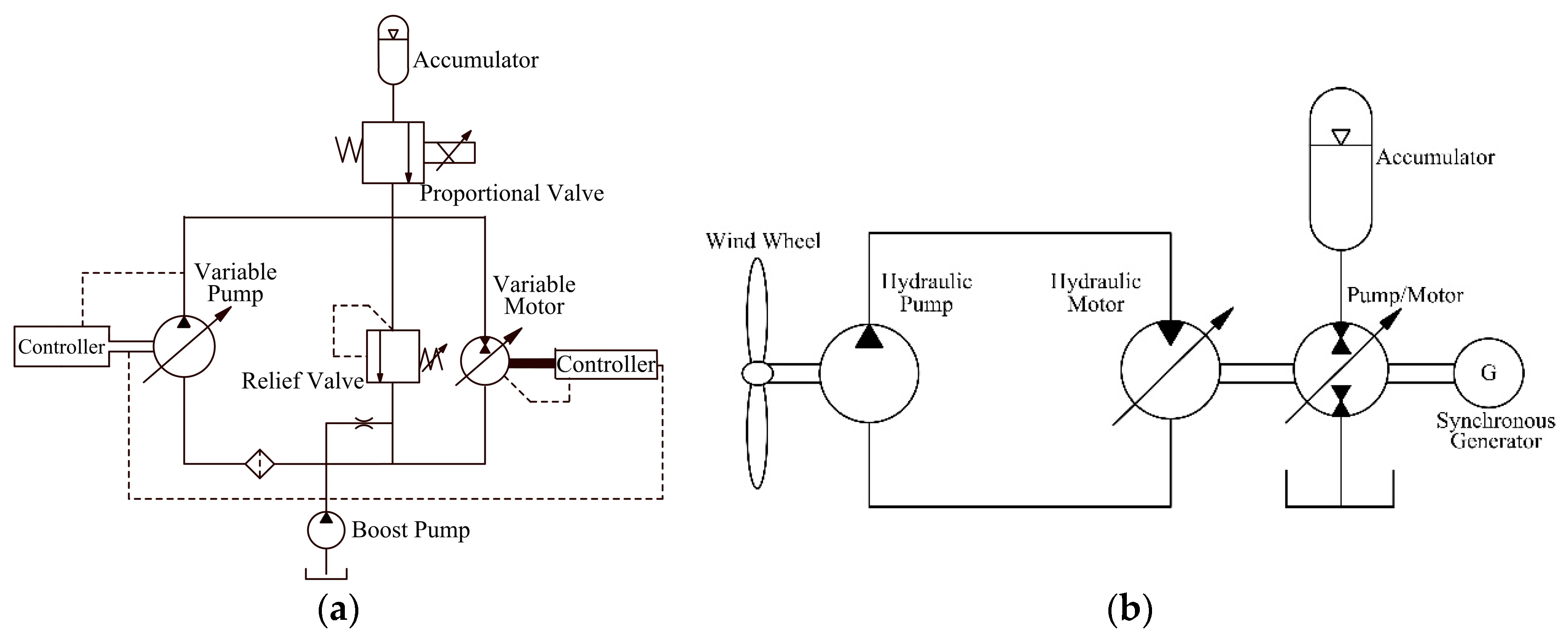
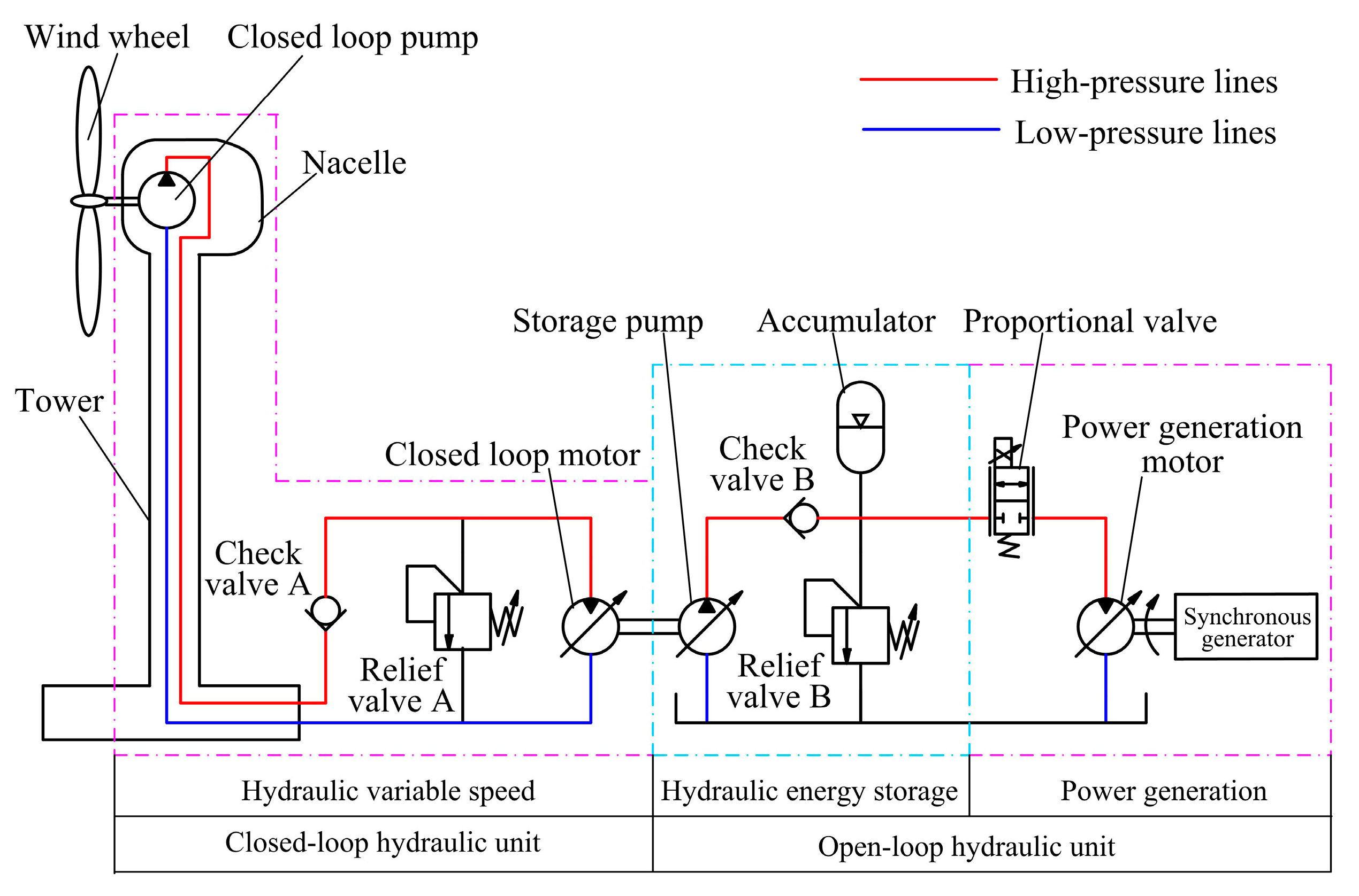
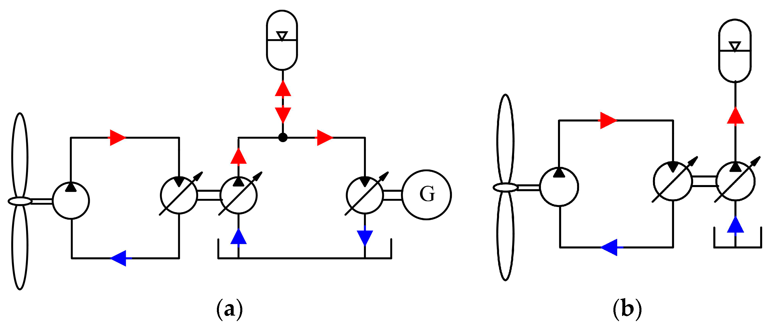
2. System Overview and Operation Mode

As shown in Figure 3, the significant difference between this storage type wind turbine and the other ones is that it consists of two hydraulic transmissions: the closed loop and the open loop. Those two are connected through the shaft between the closed loop motor and the storage pump. Moreover, the whole hydraulic system can be divided into three distinct parts according to their own functions. They are, respectively, hydraulic variable speed, hydraulic energy storage, and power generation. The closed loop part is a typical fixed pump control variable motor hydraulic system and takes on the role of converting the variable wind wheel speed into the constant motor speed, which enables the storage pump to work at the allowable speed. The open loop one performs wind energy storage and generates electricity functions. The storage pump driven by the closed loop motor transforms the mechanical energy from the closed loop unit into hydraulic energy that is directly stored in the accumulator and converted into electrical energy by means of the power generation motor and the synchronous generator. The relief valve A and B play a safety protection role to prevent the damage of the hydraulic system caused by excessive pressure. The reverse flow of high-pressure oil is arrested by the check valves A and B to avoid undesirable operation of the wind turbine. We define the joint operation of the accumulator and synchronous generator as an electric power generation model, as displayed in Figure 4a. The power generation can be isolated from the hydraulic energy storage by controlling the proportional valve. If the proportional valve is shut off, the power generation stops working. Thus, wind energy captured by the wind wheel is completely stored in the accumulator, which is called the wind energy storage model. Figure 4b shows the oil flow direction in the wind energy storage model.
The storage type wind turbine proposed in this paper has the following prominent advantages:
(1) With the addition of the accumulator, the working pressure of the open loop unit will have only gentle variations under violent wind fluctuation, which makes it much easier to achieve the constant speed control of the synchronous generator. That is because the motor speed control, by adjusting its displacement, is sophisticated.
(2) The wind turbine with hybrid hydraulic transmission has a higher efficiency of wind energy storage because the accumulator is connected directly to the high-pressure line of the open loop unit.
(3) The accumulator can be shared by multiple wind turbines, which will reduce the costs of energy storage system construction.
(4) The components of the hydraulic system are all readily available from several commercial companies, and thus this hydraulic wind turbine becomes at once a reality.
In conclusion, It is no problem in the electric power generation model if the storage type wind turbine works properly in the wind energy storage model, as the wind energy storage model is crucial to this storage type wind turbine. Consequently, the speed control of the wind wheel and the storage manipulation of wind energy in the wind energy storage model are chosen as the study subjects in this paper.

3. Mathematical Model

3.1. Wind Turbine

The wind wheel of the wind turbine captures wind energy and transforms it into the mechanical energy that drives the closed loop pump. The output power PW and torque TW of the wind wheel are expressed as follows:
P w = 1 2 ρ π R 2 C p v 3
T w = 1 2 ρ π R 2 C p v 3 / ω w
where ρ represents the air density. R is the radius of the rotor blade. v is the velocity of the wind blowing the wind turbine. ωw is the rotating speed of the wind wheel. Cp is the function of the tip speed ratio λ and the pitch angle β, which indicates the wind energy utilization ability of the wind turbine. The mathematical expression for the wind energy utilization coefficient Cp and the tip speed ratio λ are described as in ref. [24]:
C p = 0.5176 ( 116 λ i 0.4 β 5 ) e 21 λ i + 0.0068 λ
1 λ i = 1 λ + 0.08 β 0.035 β 3 + 1
λ = R ω w v

3.2. Hydraulic Variable Speed

3.2.1. Closed Loop Pump

The closed loop pump in the nacelle of the wind turbine has a fixed displacement, which converts the mechanical energy from the wind wheel into hydraulic energy. It is coupled to the wind wheel via the rotor shaft. The wind wheel speed ωw and the closed loop pump speed ωp are the same. The output flow Qp and driving torque Tp of the closed loop pump are defined as:
Q p = V p ω p η V p
T p = V p ( P p o P p i ) / η m p
where Vp is the volumetric displacement of the closed loop pump. Ppo and Ppi are the outlet and inlet pressure of the pump. ηvp and ηmp are the volumetric efficiency and mechanical efficiency of the pump respectively.

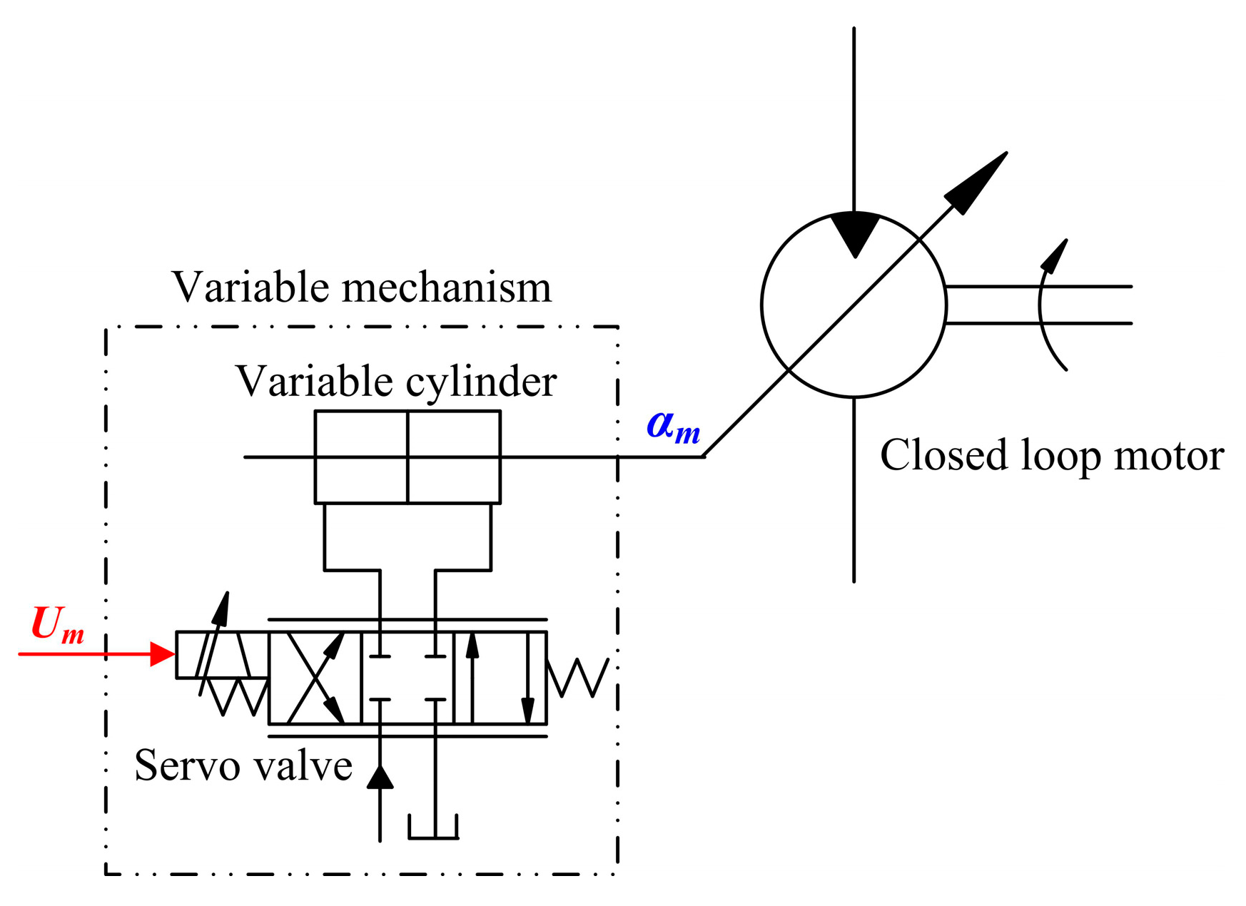
3.2.2. Closed Loop Motor

The closed loop motor is installed on the ground and is connected to the closed loop pump by hydraulic lines. The displacement of the closed loop motor can vary in order to transform the low speed of the wind wheel into the high speed of the storage pump. The displacement change is implemented by a variable mechanism integrated into the closed loop motor, which is demonstrated in Figure 5. In fact, the variable mechanism is a valve controlled cylinder position hydraulic servo system [25]. The inflow flow Qm and output torque Tm of the closed loop motor are calculated as:
Q m = α m V m ω m / η v m
T m = α m V m ( P m o - P m i ) η m m
where Vm is the maximum displacement of the closed loop motor. αm is the displacement coefficient and varies between zero and one. Pmo and Pmi represent the outlet and inlet pressure of the motor respectively. The volumetric and mechanical efficiency of the closed loop motor are indicated by ηvm and ηmm.
The variable mechanism can be regarded as a first order inertia system and its transfer function is as follows:
α m ( s ) U m ( s ) = K T s + 1
where Um is the control signal of the servo valve. K is the closed loop gain of the variable mechanism. T is the time constant of the first order inertia system.

3.3. Hydraulic Energy Storage

3.3.1. Storage Pump

The storage pump plays a vital role in the storage operation of wind energy, which can be used to convert energy absorbed by the wind wheel into hydraulic energy which is easily saved through high pressure oil. Because the accumulator is directly attached to the high pressure lines of the open loop unit, the working pressure of the storage pump is the hydraulic accumulator pressure Pa. A variable pump must be adopted to adapt the pressure variation of the accumulator. The variation characteristics of the storage pump displacement are identical to the closed loop motor. The output flow Qs and driving torque Ts of the storage pump are given by the following equation:
Q s = α s p V s p ω s p η s p v
T s = α s p V s p P a / η s p m
where Vsp is the maximum displacement of the storage pump. αsp and ωsp are the displacement coefficient and speed of the storage pump. ηspv and ηspm represent the volumetric and mechanical efficiency.

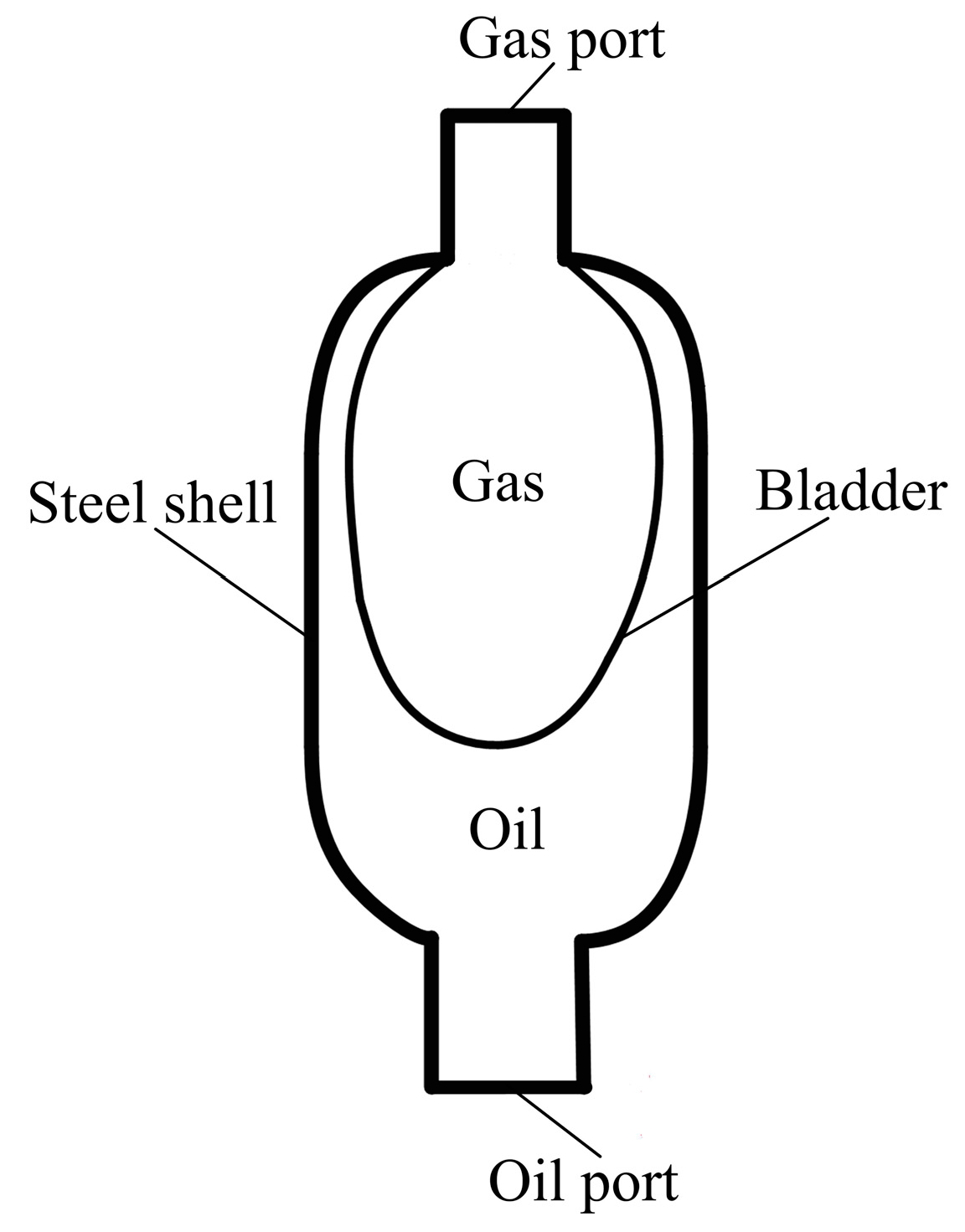
3.3.2. Hydraulic Accumulator
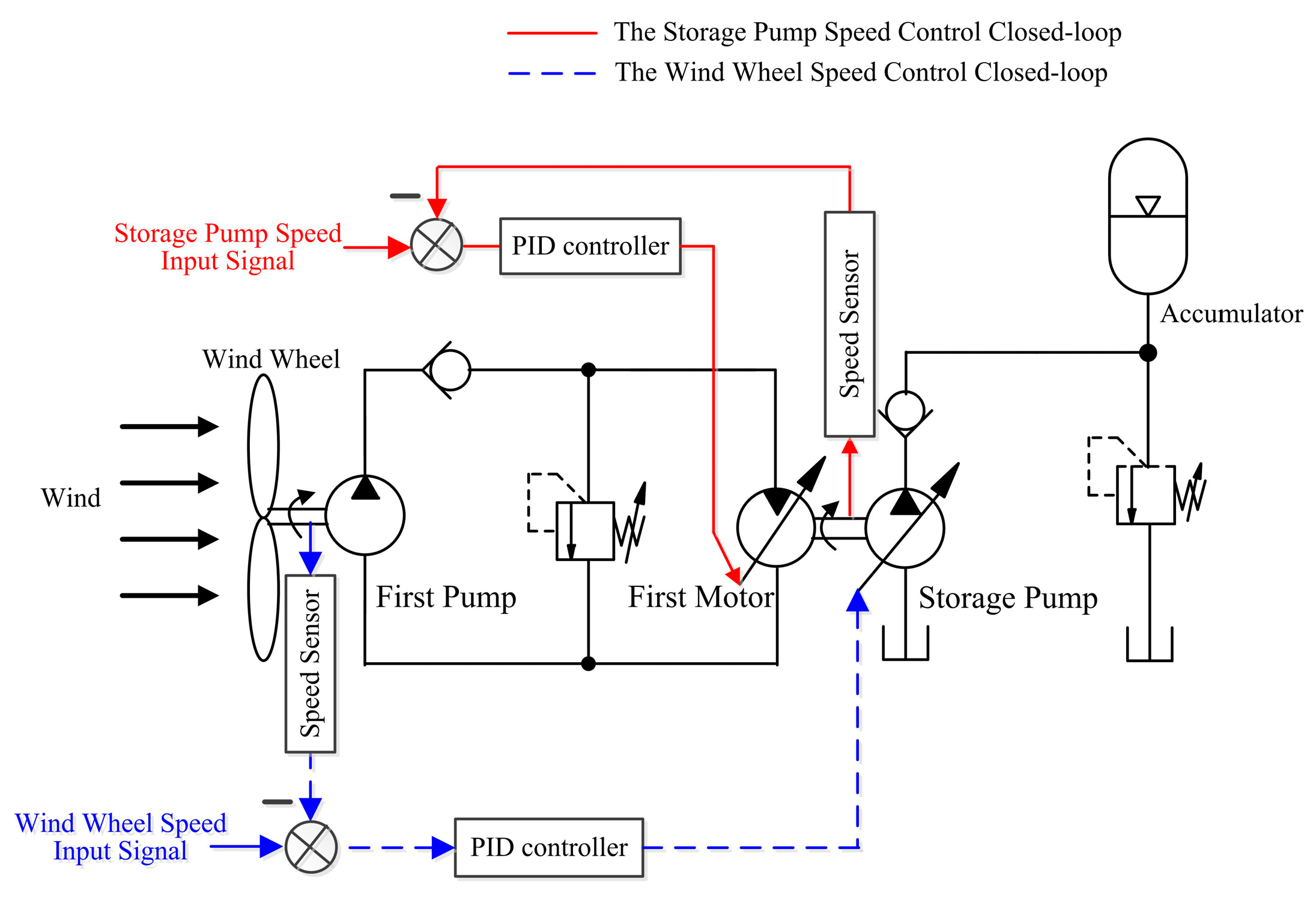
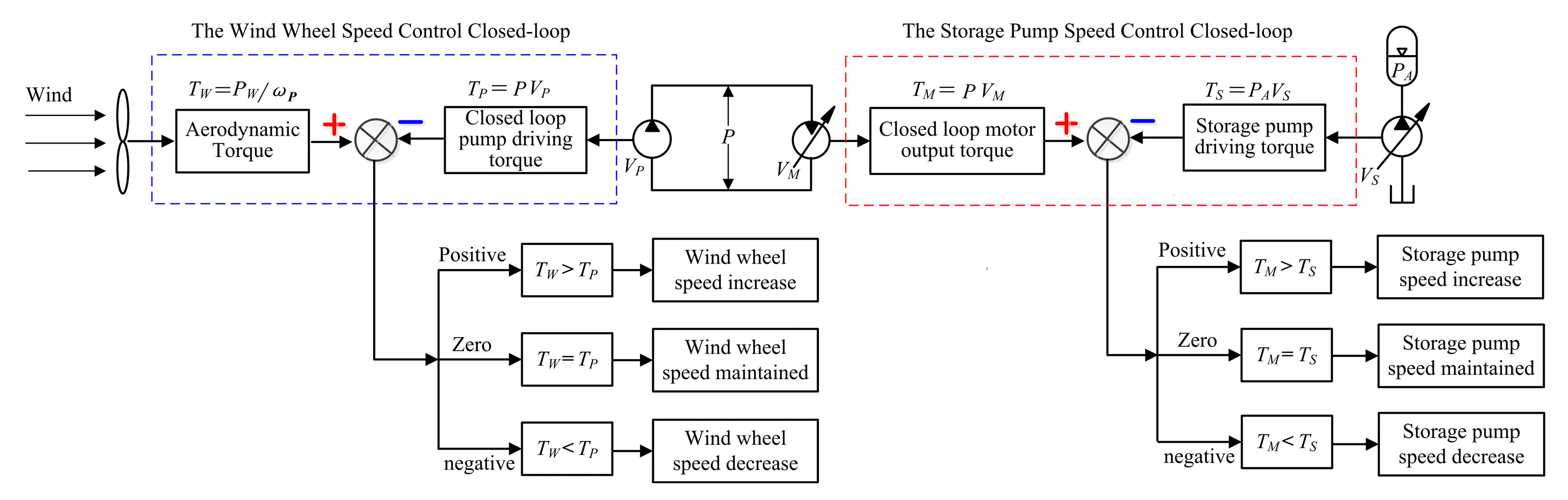
Considering the cost of the storage energy system, the storage type wind turbine experimental prototype chooses a bladder type accumulator. It is mainly made up of bladder and steel shell, as shown in Figure 6. The bladder is full of nitrogen gas via the gas port in the top of the bladder accumulator. In the process of hydraulic energy storage, hydraulic oil flows into the steel shell through the oil port that is at the bottom and squeezes the bladder. The nitrogen gas volume decreases, and its pressure rises. In this way hydraulic energy is stored as the pressure energy of nitrogen gas. The energy release process is contrary to the storage and hydraulic oil squirts into the hydraulic system on account of the nitrogen gas expansion. Assuming the compression process of nitrogen gas in the bladder submits to the ideal gas law, the nitrogen gas pressure Pa and volume Va follow the expressions below [26].
P a V a n = P 0 V 0 n
P a = P 0 V 0 n V a n = P 0 V 0 n ( V 0 + Q a dt ) n
Q a = V 0 P 0 1 n n P a n + 1 n d P a d t
where P0 and V0 represent the pre-charge pressure and initial volume of nitrogen gas in the bladder. Qa is the charge or discharge flow of the accumulator. n is 1 for an isothermal compression and 1.4 for an adiabatic compression.

4. Control Scheme

A double closed loop control strategy is proposed, which makes the wind wheel work at the expected speed and maintains the storage pump speed nearly constant. The schematic diagram of the double closed loop control is shown in Figure 7 which contains the speed control closed loops of the wind wheel and storage pump. In the speed closed loop of the wind wheel, the actual speed of the wind wheel is detected by the speed sensor and compared with the given signal to obtain the speed deviation signal; the deviation signal processed by the PID controller is used to adjust the displacement of the hydraulic storage pump. In this way, the wind wheel speed can change with the wind speed, which contributes to the maximum absorption and utilization of wind energy. The speed closed loop of the storage pump has the same system structure and operating principle. Even though the two speed control loops are similar, they are two different types of control system. One is the wind wheel speed servo control system, the other is the constant storage pump speed control system. For the former, it is necessary that the wind wheel follows the change of the input signal as soon as possible; The latter requires that the storage pump speed should be equal or close to the input value in order to achieve a high efficiency and long life of the storage pump.
The speed regulation of the wind wheel and storage pump is actually realized by implementing torque comparison. Figure 8 displays all the torques in this storage type wind turbine and the relationships between them. The torques imposed on the wind wheel come from its output aerodynamic torque TW and the closed loop pump driving torque TP. When TW is greater than TP, the wind wheel will accelerate under the action of the positive net moment and the speed rises. If the two are equal, the wind wheel is at equilibrium, and the wind wheel speed is left at the original. The driving torque of the closed loop pump acts as a brake on the wind wheel and the wind wheel slows down, in case the difference between them is negative. The storage pump suffers from the closed loop motor output torque TM and its driving torque TS that is the product of the accumulator pressure PA and displacement VS. The storage pump motion caused by TM and TS is consistent with the closed loop pump.

5. Simulation and Analysis

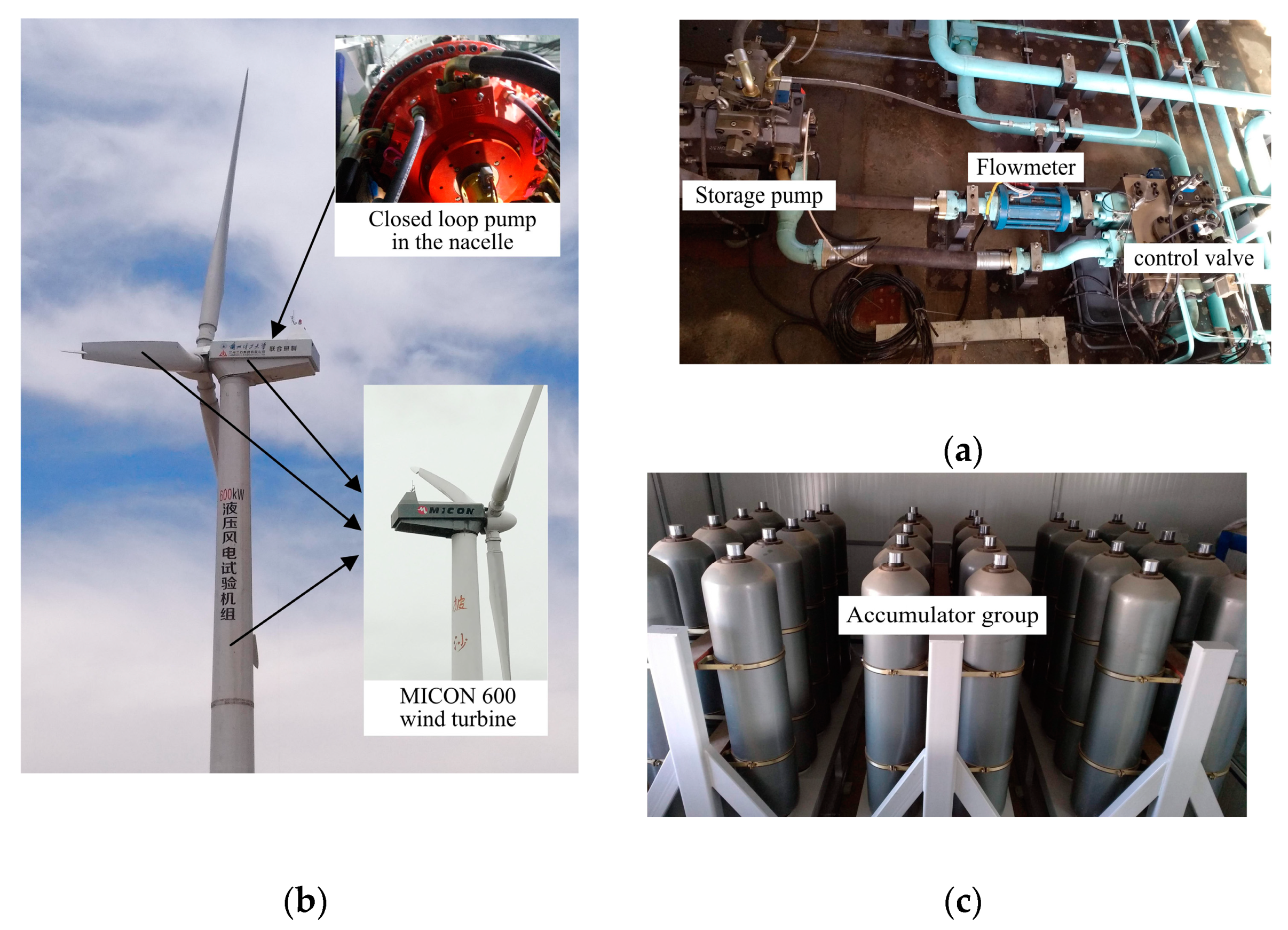
5.1. The Parameters of the 600 kW Storage Type Wind Turbine

5.1.1. Wind Turbine

Micon 600 is a constant speed fixed pitch wind turbine which was very popular once. A withdrawn Micon 600 was selected to set up the 600 kW storage type wind turbine experimental platform by Lanzhou University of Technology and Lanzhou LS Group. The relationship between after and before the reform and transformation of Micon 600 is shown in Figure 9a. The parameters of the Micon 600 wind turbine are listed in Table 1.

5.1.2. Hydraulic Variable Speed

The closed loop pump is the most important and critical component of this storage type wind turbine, which transmits the mechanical power from the wind wheel into hydraulic power. The radial piston pump is best for the closed loop pump because of low speed and high torque, but its displacement is fixed. In this wind turbine, a Hagglunds motor was chosen as the closed loop pump and installed in the nacelle, as shown in Figure 9a. The closed loop motor employs an axial piston motor by Rexroth to complete the variable speed. The main parameters of the hydraulic variable speed are shown in Table 2.

5.1.3. Hydraulic Energy Storage

The storage pump has the same type and maximum displacement as the closed loop motor. The output flow of the storage pump can be measured and recorded through the flowmeter. The 30 hydraulic bladder accumulators are integrated as the accumulator group to store the extra energy, which can provide a total capacity of 6000 L. They are shown in Figure 9b,c. The parameters of the hydraulic energy storage are described in Table 3.

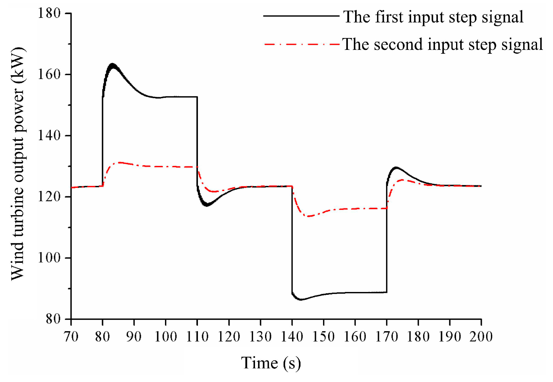
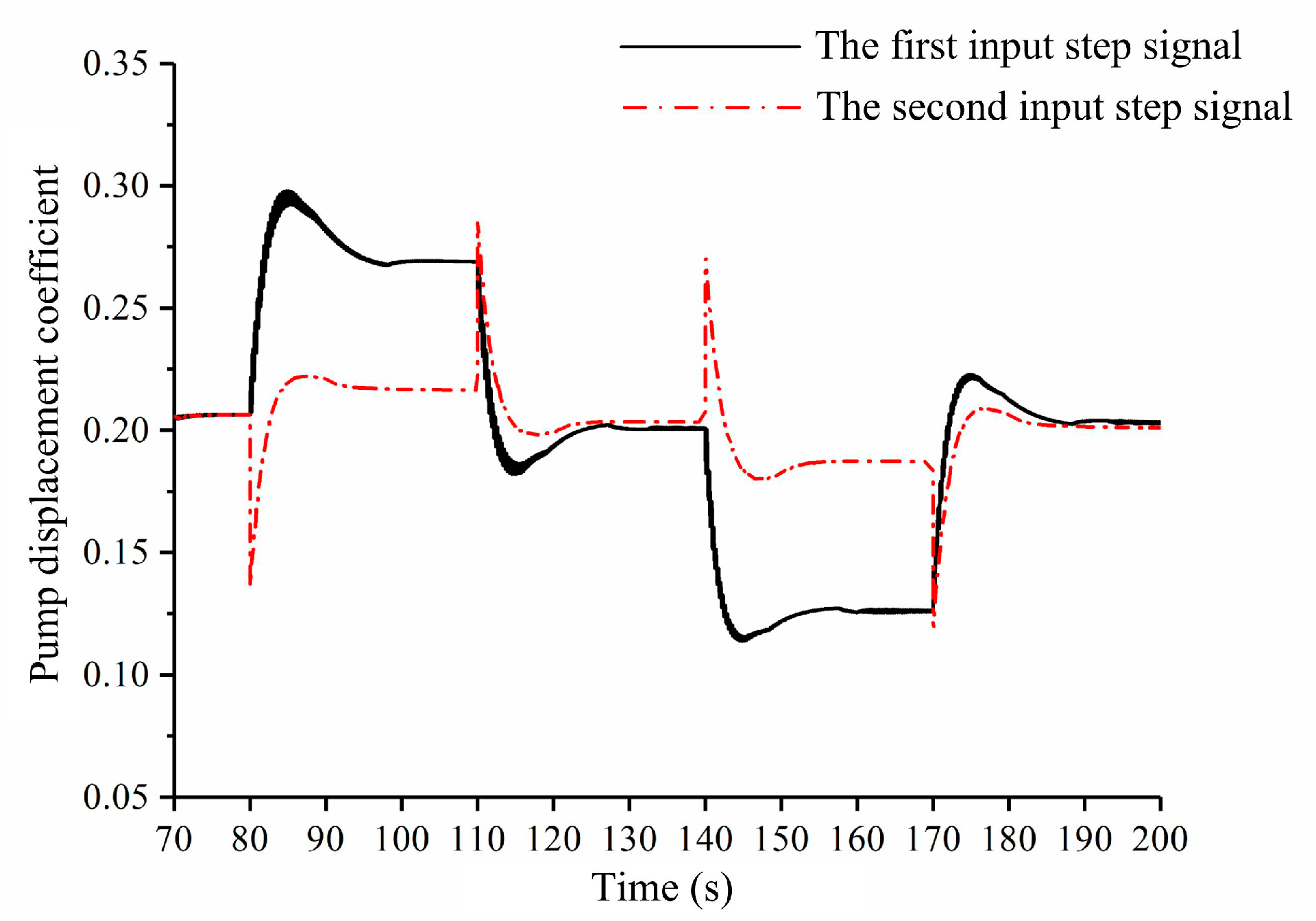
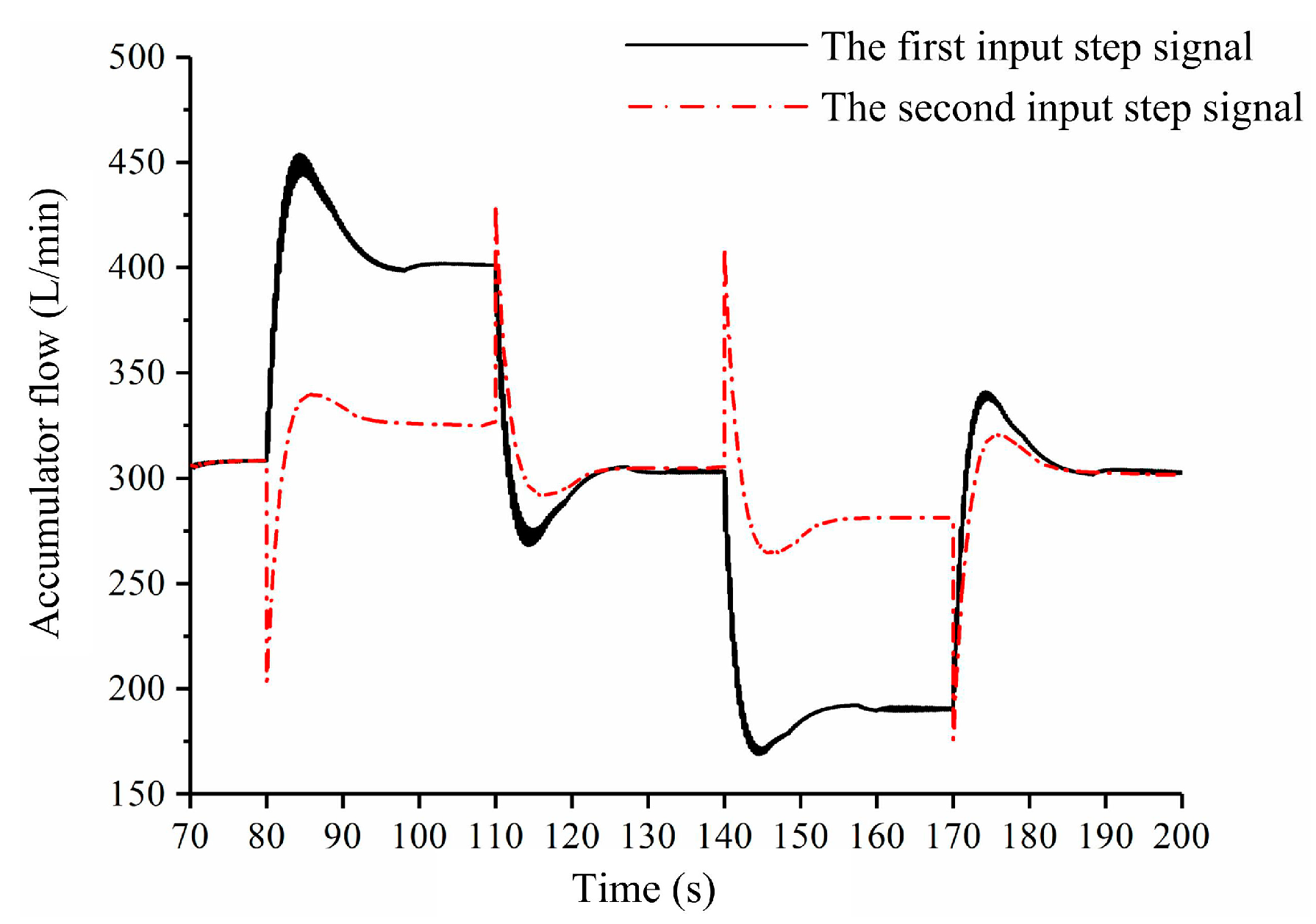
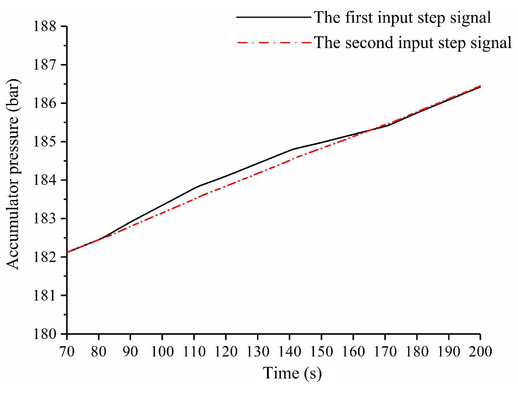
5.2. Time Domain Simulations
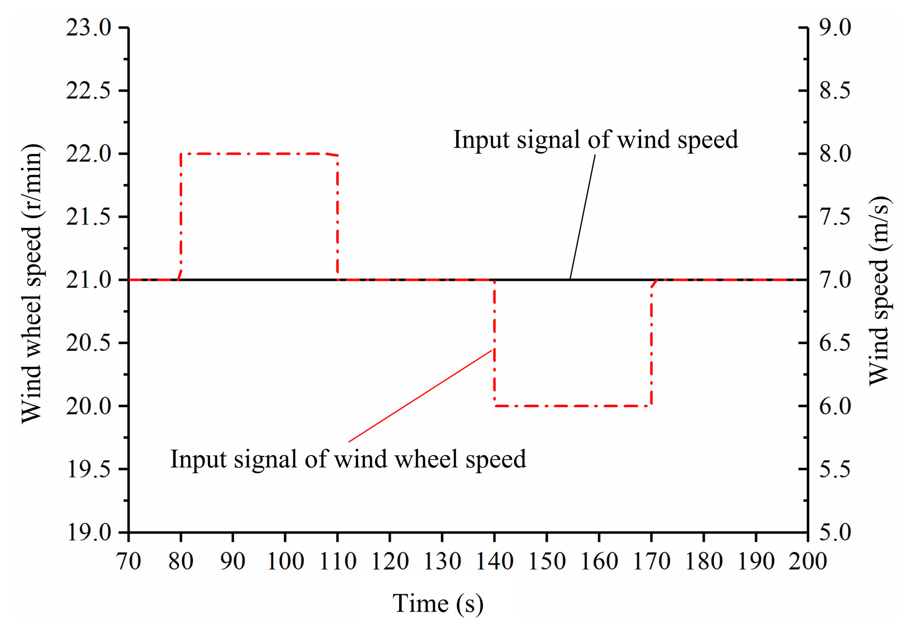
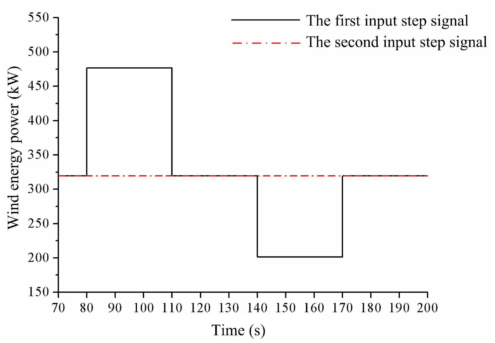
5.2.1. System Input

In the light of the control schematic diagram displayed in Figure 7, the whole system comprises three input signals: the input of wind speed, the two given signals of the wind wheel speed closed loop, and the storage pump signal. The given signal of the storage pump speed remains the same during the work of the wind turbine and is set to 1500 r/min now. The input signal of the wind wheel speed will have to change with wind speed to maximize the wind energy captured by the wind turbine. The two different combinations of wind speed input and wind wheel speed given signal were used as the system input to investigate the dynamic response of this wind turbine. In the first input step signal, as shown in Figure 10, the input wind speed follows the step change from 6 m/s to 8 m/s, and the other is always maintained at 21 r/min. On the contrary, the input of the wind wheel speed in the second input step signal, as shown in Figure 11, experiences a sudden change in the range of 20 r/min to 22 r/min. The wind speed is 7 m/s all the time.

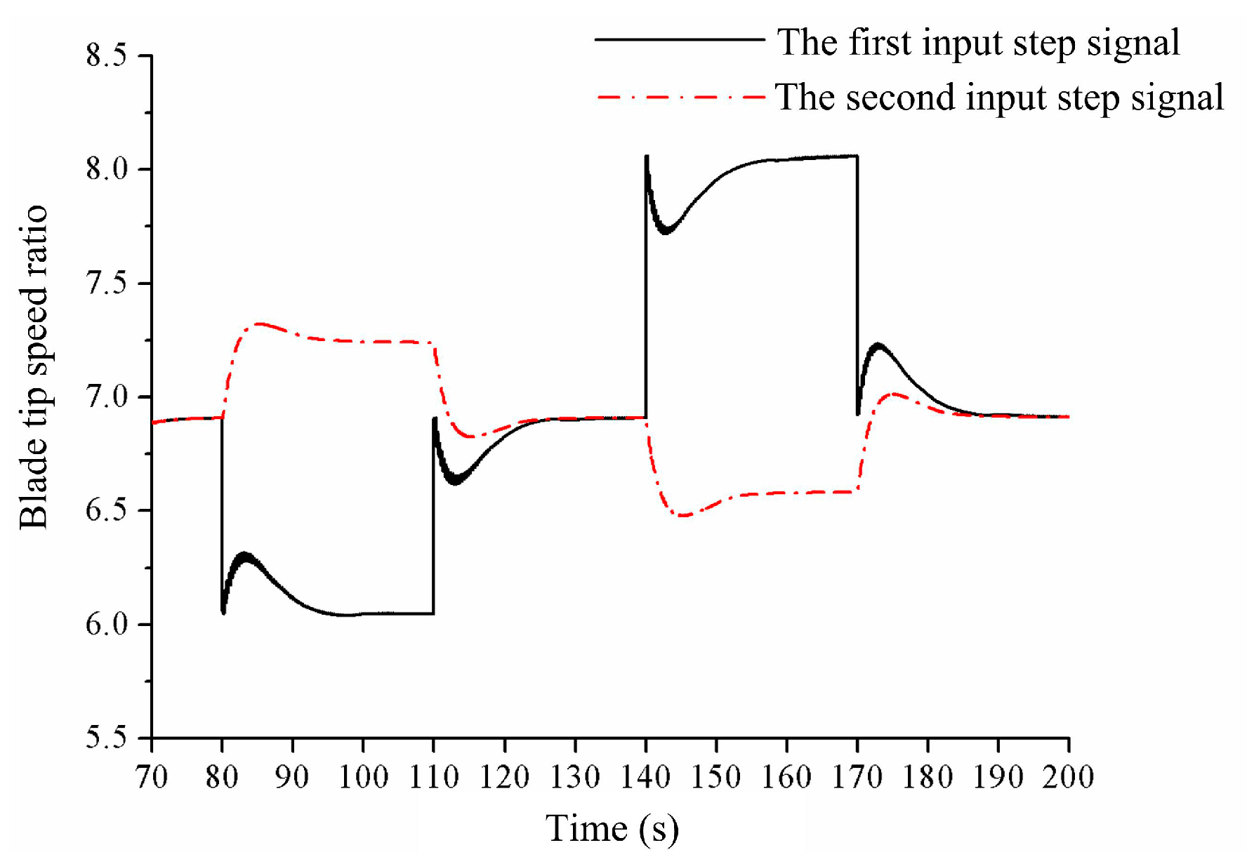
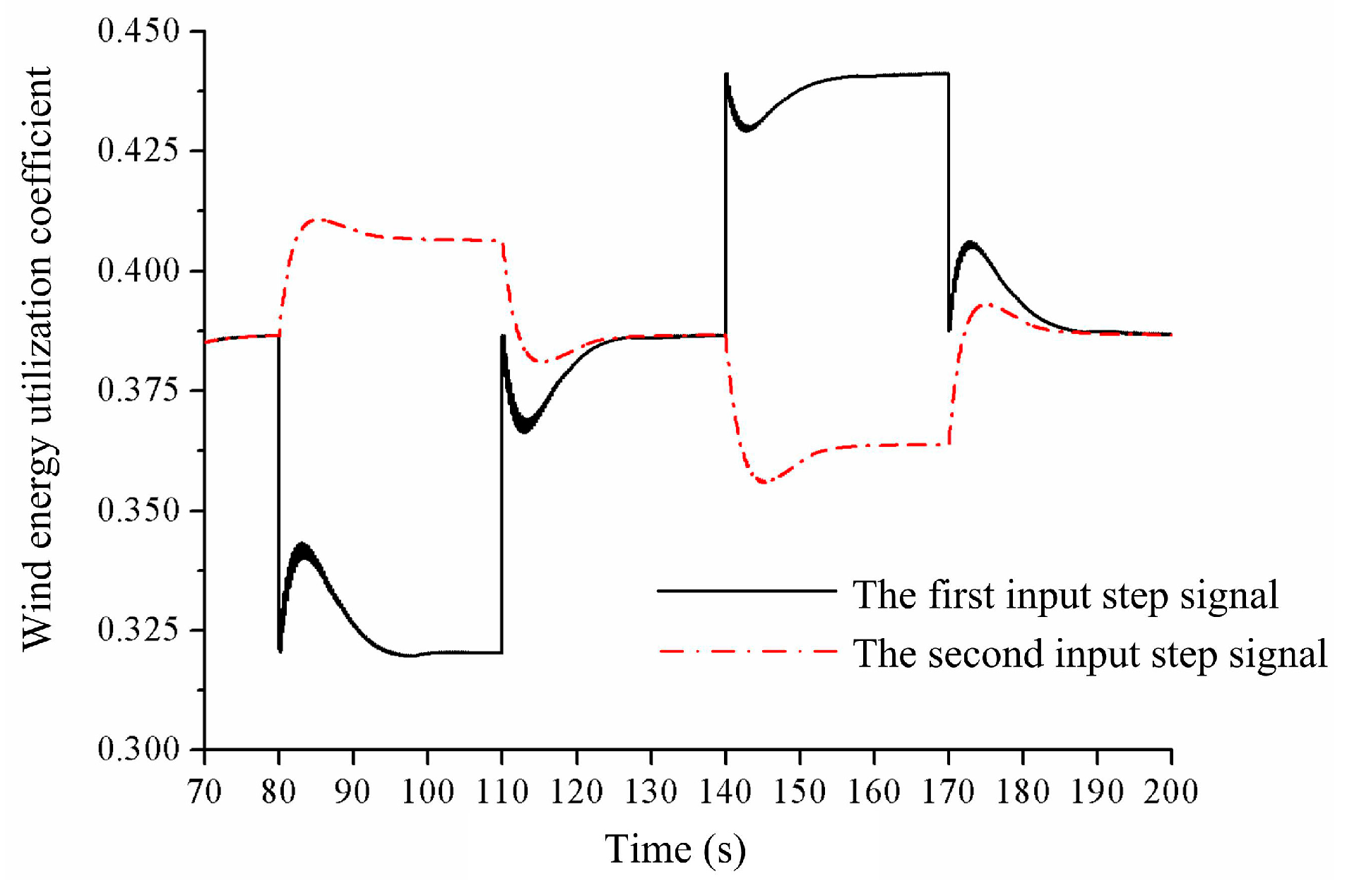
5.2.2. Simulation Results

To verify the validity of the storage type wind turbine proposed and to study the dynamic performance of double closed loop control, the model of the system in the wind energy storage model was established in the Matlab/Simulink environment (version 6.5, MathWorks Company, Natick, MA, USA )and the simulations in the time domain executed with the two input signals from the previous section.
The change curves of wind wheel speed are shown in Figure 12. It shows that when the wind speed increases from 7 m/s to 8 m/s at 80 s, the wind wheel speed first rises to nearly 22 r/min at a faster pace. This is because the wind wheel output torque is greater than the driving one of the closed loop pump. Under the effect of the speed closed loop of the wind wheel, the resistance torque on the wind wheel gradually increases, the wind wheel speed reverts to the initial value of 21 r/min after about 15 s. When the wind speed suddenly decreases, the wind wheel speed rapidly drops to 20 r/min, and then backs to 21 r/min after the same time. The change process of the wind wheel speed under the second input signal is similar, and both of them overshoot. However, the speed overshoot of the wind wheel with the wind speed step is larger.
According to the wind energy power curve shown in Figure 13, the wind energy power sharply increases from 320 kW (7 m/s) to 475 kW (8 m/s) at 80 s and then suddenly decreases from 320 kW (7 m/s) to 200 kW (6 m/s) at 140 s.
From Figure 14 and Figure 15, it can be seen that when the wind speed rises at 80 s, the blade tip speed ratio reduces from 6.85 to 6.1, and the wind energy utilization coefficient correspondingly declines from 0.38 to 0.32. The change direction of the blade tip speed ratio and wind energy utilization coefficient is inverted with a sudden wind speed reduction. The varying trend of them in the second input step signal is opposite to that of the first.
Figure 16 shows with the increase of wind energy power and the decrease of the wind energy utilization coefficient, the wind wheel output power rises from 123 kW to 152 kW at 110 s. The wind wheel output power in the second input step signal has a small change for the little increase of the wind energy utilization coefficient and the constant wind energy power.
The speed and displacement curves of the closed loop motor are displayed in Figure 17 and Figure 18. It can be shown that the changing trend of the closed loop motor displacement with the two input step signals is consistent with that of the wind wheel speed. At the same time, the closed loop motor works at a speed of 1500 ± 50 r/min, which does not exceed the speed limit of the energy storage pump.
Figure 19 and Figure 20 show the displacement change and energy storage flow curves of the storage pump under the two types of given input signals. From Figure 19, we can see that the displacement of the storage pump also increases rapidly when the wind speed step occurs at 80 s, which establishes the torque balance of the wind wheel and keeps the wind wheel speed constant. When the given signal of the wind wheel speed has a step rise at 80 s, the displacement of the storage pump diminishes quickly to accelerate the wind wheel. Figure 20 shows that the changing trend of the charging flow of the hydraulic accumulator is the same as that of the storage pump displacement. The charging flow in the first input step signal increases from 305 L/min to 400 L/min but it has an increase of 25 L/min within the second one.
Figure 21 shows the working pressure of the hydraulic accumulator. It can be seen that the accumulator pressures under two input step signals slowly rise from 182 bar to 186 bar simultaneously on account of hydraulic energy storage. There is a higher pressure rising rate at 80 s in the first input step signal. That is because the corresponding charging flow of the hydraulic accumulator is far greater than the other one.

6. Conclusions

Aiming to resolve the poor quality of power generation caused by the randomness and fluctuation of wind energy and the unavailability of a variable pump connected directly to the wind wheel, this paper presents an innovative storage type wind turbine using hybrid hydraulic transmission. The storage type wind turbine can operate in two different modes: electric power generation and wind energy storage. Because the wind energy storage mode is critical to the storage type wind turbine, the mathematical model of the wind turbine in this mode was established.
A double closed loop control method was used to achieve the speed control of the wind wheel and the storage pump. The time domain dynamic responses of the storage type wind turbine under the two input step signals were simulated. The simulation results demonstrate that the proposed storage type wind turbine in cooperation with a double closed loop control strategy is feasible. The double closed loop control scheme studied in this work can accomplish the speed control goal of the wind wheel and the storage pump with a high performance. In addition, in order to further verify and improve the accuracy and reliability of the simulation results, the relevant experimental verification should be carried out on a 600 kW storage type wind turbine experimental platform.

Author Contributions

L.W. and Z.L. conceived the research; Z.L., Y.T. and D.Y. achieved the simulation model and control principle design; Z.L. and Y.T. wrote the paper together; Y.T. and P.Z. performed the arrangement and analysis of the simulation data; L.W. and D.Y. critically revised the paper and provided many valuable and constructive suggestions.

Funding

This research was funded by the National Natural Science Fund Project of China (51765033), the Gansu Provincial Science and Technology Major Project of China (17ZD2GA010), the Gansu Provincial Natural Science Foundation of China (17JR5RA127) and the Gansu Provincial Natural Science Foundation of China (18JR3RA155).

Conflicts of Interest

The authors declared no potential conflicts of interest with respect to the research, authorship, and publication of this article.

References

  1. Enevoldsen, P.; Xydis, G. Examining the trends of 35 years growth of key wind turbine components. Energy Sustain. Dev. 2019, 50, 8–26. [Google Scholar] [CrossRef]
  2. Cheng, Q.M. Overview of the development of control technique for wind power generation system. Process Autom. Instrum. 2012, 33, 1–8. [Google Scholar]
  3. Wang, T.; Han, Q.; Chu, F.; Feng, Z. Vibration based condition monitoring and fault diagnosis of wind turbine planetary gear-box: A review. Mech. Syst. Signal Process. 2019, 126, 662–685. [Google Scholar] [CrossRef]
  4. Yang, W.; Tavner, P.J.; Wilkinson, M.R. Condition monitoring and fault diagnosis of a wind turbine synchronous generator drive train. IET Renew. Power Gener. 2009, 3, 1–11. [Google Scholar] [CrossRef]
  5. Bensalah, A.; Benhamida, M.; Barakat, G. Large wind turbine generators: State-of-the-art review. In Proceedings of the 2018 XIII International Conference on Electrical Machines (ICEM), Alexandroupoli, Greece, 3–6 September 2018. [Google Scholar]
  6. Cai, M.; Wang, Y.; Jiao, Z.; Shi, Y. Review of fluid and control technology of hydraulic wind turbines. Front. Mech. Eng. 2017, 12, 312–320. [Google Scholar] [CrossRef] [Green Version]
  7. Rybak, S.C. Description of the 3 Mw Swt-3 Wind Turbine at San Gorgonio Pass, California, Bien Wind Energy Conference Workshop; Bendix Corp., Environment and Technology Office: Sylmar, CA, USA, 1982; Volume 1, pp. 193–206. [Google Scholar]
  8. Browning, J.R.; Manwell, J.F.; Mcgowan, J.G. A techno-economic analysis of a proposed 1.5 mw wind turbine with a hydrostatic drive train. Wind Eng. 2009, 33, 571–586. [Google Scholar] [CrossRef]
  9. Doe, E. Advanced Wind Turbine Drivetrain Concepts: Workshop Report; No. DOE/GO-102010-3198; National Renewable Energy Lab (NREL): Golden, CO, USA, 2010.
  10. Thomsen, K.E.; Dahlhaug, O.; Niss, M.O.K.; Haugseta, S.K. Technological advances in hydraulic drive trains for wind turbines. Energy Procedia 2012, 24, 76–82. [Google Scholar] [CrossRef]
  11. Mortensen, K.A.; Henriksen, K.H. Efficiency Analysis of a Radial Piston Pump Applied in a 5mw Wind Turbine with Hydraulic Transmission; Aalborg University: Aalborg, Denmark, 2011; pp. 2–3. [Google Scholar]
  12. Schmitz, J.; Vatheuer, N.; Murrenhoff, H. Development of a hydrostatic transmission for wind turbines. In Proceedings of the 7th International Fluid Power Conference, Aachen, Germany, 22–24 March 2010. [Google Scholar]
  13. Schmitz, J.; Vatheuer, N.; Murrenhoff, H. Hydrostatic drive train in wind energy plants. RWTH Aachen Univ. IFAS Aachen Ger. 2011. Available online: https://sari-energy.org/oldsite/PageFiles/What_We_Do/activities/EWEC_2011_Brussels/Presentations/Scientifics573.pdf (accessed on 27 May 2019).
  14. Schmitz, J.; Diepeveen, N.F.B.; Vatheuer, N.; Murrenhoff, H. Dynamic transmission response of a hydrostatic transmission measured on a test bench. In Proceedings of the European Wind Energy Conference and Exhibition (EWEA 2012), Copenhagen, Denmark, 16–19 April 2012. [Google Scholar]
  15. Eaton. Microgrid Content Journey [EB/OL]. 2010. Available online: http://www.eaton.com/FTC/utilities/IntelligentMicrogrids/index.htm (accessed on 27 May 2019).
  16. Eriksen, P.B.; Ackermann, T.; Abildgaard, H.; Smith, P.; Winter, W.; Garcia, J.M.R. System operation with high wind penetration. IEEE Power Energy Mag. 2005, 3, 65–74. [Google Scholar] [CrossRef]
  17. Dutta, R. Modeling and Analysis of Short Term Energy Storage for Mid-Size Hydrostatic Wind Turbine; The University of Minnesota Press: Minnesota, MN, USA, 2012. [Google Scholar]
  18. Vaezi, M.; Izadian, A. Energy storage techniques for hydraulic wind power systems. In Proceedings of the 2014 International Conference on Renewable Energy Research and Application (ICRERA), Milwaukee, WI, USA, 19–22 October 2014. [Google Scholar]
  19. Díaz-González, F.; Sumper, A.; Gomis-Bellmunt, O.; Villafáfila-Robles, R. A review of energy storage technologies for wind power applications. Renew. Sustain. Energy Rev. 2012, 16, 2154–2171. [Google Scholar] [CrossRef]
  20. Whitby, R.D. Hydraulic fluids in wind turbines. Tribol. Luburication Technol. 2010, 66, 72. [Google Scholar]
  21. Liu, Z.G.; Yang, G.; Wei, L.J.; Yue, D.L. Variable speed and constant frequency control of hydraulic wind turbine with energy storage system. Adv. Mech. Eng. 2017, 9, 1–10. [Google Scholar] [CrossRef]
  22. Liu, Z.G.; Yang, G.L.; Wei, L.J.; Yue, D.L.; Tao, Y.H. Research on the robustness of the constant speed control of hydraulic energy storage generation. Energies 2018, 11, 1–14. [Google Scholar] [CrossRef]
  23. Wei, L.J.; Liu, Z.G.; Zhao, Y.Y.; Wang, G.; Tao, Y.H. Modeling and control of a 600 kw closed hydraulic wind turbine with an energy storage system. Appl. Sci. 2018, 8, 1–18. [Google Scholar] [CrossRef]
  24. Heier, S. Grid Integration of Wind Energy: Onshore and Offshore Conversion Systems, 3rd ed.; John Wiley & Sons: West Sussex, WS, UK, 2014; pp. 43–44. ISBN 978-1-119-96294-6. [Google Scholar]
  25. Merritt, H. Hydraulic Control Systems; John Wiley & Sons: Hoboken, NJ, USA, 1991; pp. 152–156. ISBN 978-0-471-59617-2. [Google Scholar]
  26. Pei, R.; Shen, M.J.; Xiao-Ming, W.U. Working parameter selection of bladder-type accumulator considering the effects of the poly index and temperature. Chin. Hydraul. Pneum. 2014, 12, 96–99. [Google Scholar]
Figure 1. The fundamental principle of the hydraulic wind turbine.
Processes 07 00397 g001
Figure 2. (a) The schematic diagram of Artemis Intelligent Power hydraulic wind turbine; (b) The schematic diagram of the Rahul Dutta hydraulic wind turbine.
Processes 07 00397 g002
Figure 3. The schematic diagram of the storage type wind turbine.
Processes 07 00397 g003
Figure 4. (a) The oil flow direction in the electric power generation model; (b) The oil flow direction in the wind energy storage model.
Processes 07 00397 g004
Figure 5. The schematic diagram of the variable motor.
Processes 07 00397 g005
Figure 6. The structure diagram of the bladder accumulator.
Processes 07 00397 g006
Figure 7. The schematic diagram of the double closed-loop control method.
Processes 07 00397 g007
Figure 8. The torque relationship of the storage type wind turbine.
Processes 07 00397 g008
Figure 9. The 600 kW storage type wind turbine experimental platform: (a) The storage pump; (b) The Micon 600 kW wind turbine and closed loop pump; (c) The hydraulic accumulator group.
Processes 07 00397 g009
Figure 10. The first input step signal.
Processes 07 00397 g010
Figure 11. The second input step signal.
Processes 07 00397 g011
Figure 12. Wind wheel speed curve.
Processes 07 00397 g012
Figure 13. Wind energy power curve.
Processes 07 00397 g013
Figure 14. The blade tip speed ratio curve.
Processes 07 00397 g014
Figure 15. The wind energy utilization coefficient curve.
Processes 07 00397 g015
Figure 16. The wind wheel output power curve.
Processes 07 00397 g016
Figure 17. The closed loop motor speed curve.
Processes 07 00397 g017
Figure 18. The closed loop motor displacement curve.
Processes 07 00397 g018
Figure 19. The hydraulic storage pump displacement curve.
Processes 07 00397 g019
Figure 20. The energy storage flow curve.
Processes 07 00397 g020
Figure 21. The energy storage pressure curve.
Processes 07 00397 g021
Table 1. The parameters of the Micon 600 wind turbine.
ParameterSymbolValueUnit
Rated powerPrated600kW
Hub heightH46m
Rotor diameterD43m
Maximum rotor speedωm27r/min
Rated wind speedVrated15.5m/s
Cut in wind speedVin3.5m/s
Cut out wind speedVout25m/s
Moment of inertiaJW20,000kg·m2
Coefficient of viscosityBp50N·m/(r/min)
Table 2. The parameters of the hydraulic variable speed.
ParameterSymbolValueUnit
Closed loop pump displacementVcp55,300cm3/rev
Closed loop motor max displacementVcm500cm3/rev
Relief valve A cracking pressure PA210bar
Pipe diameterDcp100mm
Pipe lengthLcp115m
Table 3. The parameters of the hydraulic energy storage.
ParameterSymbolValueUnit
Energy storage pump max displacementVsp500cm3/rev
Accumulator volumeV06000L
Gas pre-charge pressureP0100bar
Accumulator working pressurePa180bar
Relief valve B cracking pressure PB250bar
Pipe diameterDop100mm
Pipe lengthLop6m

