Article

Highly Porous Graphitic Activated Carbons from Lignite via Microwave Pretreatment and Iron-Catalyzed Graphitization at Low-Temperature for Supercapacitor Electrode Materials

1
College of Engineering and Technology, Jilin Agricultural University, Changchun 130118, China
2
College of Animal Science and Technology, Jilin Agricultural University, Changchun 130118, China
*
Author to whom correspondence should be addressed.
Processes 2019, 7(5), 300; https://doi.org/10.3390/pr7050300
Submission received: 17 April 2019 / Revised: 12 May 2019 / Accepted: 16 May 2019 / Published: 21 May 2019
(This article belongs to the Section Catalysis Enhanced Processes)

Abstract

:
At present, the preparation of highly porous graphitic activated carbons (HPGACs) using the usual physical and chemical activation methods has met a bottleneck. In this study, HPGACs are directly synthesized from lignite at 900 °C. The whole process is completed by a microwave pretreatment, a graphitization conversion of the carbon framework at a low temperature using a small amount of FeCl3 (10–30 wt%), and a subsequent physical activation using CO2. Consequently, the dispersed and mobile iron species, in the absence of oxygen functional groups (removed during the microwave pretreatment), can greatly promote catalytic graphitization during pyrolysis, and, as an activating catalyst, can further facilitate the porosity development during activation. The as-obtained AC-2FeHLH-5-41.4(H) presents a low defect density, high purity, and specific surface area of 1852.43 m2 g−1, which is far greater than the AC-HLH-5-55.6(H) obtained solely by physical activation. AC-2FeHLH-5-41.4(H) as a supercapacitor electrode presents an excellent performance in the further electrochemical measurements. Such a convenient and practical method with low cost proves a scalable method to prepare HPGACs from a wide range of coal/biomass materials for industrial scale-up and applications.

1. Introduction

With limited resources and the fast consumption of fossil fuels, the development of an energy storage and utilization device with high efficiency, environmental friendliness, and sustainability is very necessary and urgently demanded [1]. Supercapacitors are a kind of the ideal energy storage system with their good features, for instance a high power density and long cycle life [2]. The high electrochemical performance of supercapacitors is closely related to the ideal physical and chemical structure of electrode materials, such as a high specific surface area (SBET) and ordered graphitic crystallite. On the other hand, a large number of interconnected porous structures can promote the ion transport capacity to shorten the diffusion length to an electrode; whereas highly ordered graphitic crystallites achieve a good conductivity [3,4]. Low-rank coal, with high reserves, volatile matter, reactivity, and a medium calorific value, is an ideal raw material for preparing activated carbons (ACs) as a supercapacitor electrode material [5]. However, low-rank coal, including those with a disordered arrangement, small microcrystals and strongly cross-linked bonds, usually presents a low specific surface area and conductivity even at high temperatures (up to 3000 °C) [6], thus, hindering their large-scale application and further development as an ideal electrode material. The conversion of low-rank coal into highly porous graphitic activated carbon (HPGACs) is very valuable, in particular for “waste-to-wealth” purposes.
In recent years, many researchers have done great work at preparing HPGACs based on low-rank coal by controllable physical or chemical activation methods. The obtained ACs provide some degree of improvement to the electrochemical performance of supercapacitors, but these methods are still unable to fully meet the low-cost, green, and high-performance preparation requirements of HPGACs. More concretely, the non-graphitizing microcrystals and a low SBET value (usually lower than 900 m2 g−1) can be formed by traditional physical activation using activation agents (such as CO2, O2, H2O) [7,8,9]. Then, the traditional chemical activation agents, using KOH [10,11], K2CO3 [12,13], ZnCl2 [14], and H3PO4 [15] (80 wt%), are typically mixed with precursor powders (20 wt%) at high temperatures, and substantial water/acid is subsequently consumed to remove the residual activation agents, which not only increases the preparation cost but also results in the environmental pollution. Hence, it is highly desirable to explore a green and low-cost method for synthesizing HPGACs.
Many researchers have found that an ordered graphitization degree can be obtained by direct high-temperature heating (>2500 °C) or by the stress graphitization of carbon sources, but the realization of these processes requires extreme experimental conditions and usually leads to a low porosity [6,16]. Remarkably, the addition of some metal catalysts (for example Ca, Mg, Na, K, Fe) can further reduce the graphitization temperature to lower than 1000 °C [17]. First, these metal catalysts can promote the decomposition of raw coals upon heating to release more carbon atoms. Then, the as-produced carbon atoms can react with the catalysts to form several carbides. Finally, the decomposition of these carbides is accompanied by the formation of an abundance of graphite microcrystals [18,19]. The specific reaction process is as follows (using iron as a catalyst) [20]:
α-Fe(s) + amorphous carbon(s) → Fe3C(s) and
Fe3C(s) → α-Fe(s) + graphitized carbon(s).
In addition, Yu et al [21] found that the formation of carbides (Fe3C) was attributed to the consumption of amorphous carbon by Fe3+. This process moves, assembles, and finally disintegrates into the graphite microcrystals. Therefore, the carburized phase maintains continuous formation and decomposition in order to help stabilize the graphite microcrystals during the whole process. However, ideal graphite carbon is difficult to obtain by only the addition of some catalysts at low pyrolysis temperatures. There are many strongly cross-linked bonds in low-rank coal, including the aliphatic structure and functional groups. Aliphatic structures (such as asymmetric CH3- and CH2-, symmetric CH2-, and symmetric CH3-) can be easily removed with an increase in the temperature at the beginning of pyrolysis. However, the removal of oxygen-containing functional groups with different thermal stabilities, is more difficult during pyrolysis and results in a disordering of the microstructure. Functional groups (such as benzoic acid), connected to the aromatic system, are stable, and their decomposition temperatures are usually higher than 600 °C, consequently, a number of carboxyl and hydroxyl groups with high thermal stability could not be removed even at 800 °C [22,23]. In our previous studies, we found that these groups with different thermal stabilities can further hinder the release of microcrystals and their ordered rearrangement, even in the presence of Fe-based catalysts. In addition, the presence of the oxygen-containing functional groups is more conducive to catalytic cracking than catalytic graphitization [24,25]. Thus, the removal of oxygen functional groups before pyrolysis is a key factor in catalytic graphitization characteristics of FeCl3 additives at low temperatures. Remarkably, oxygen-containing functional groups belong to polar groups, which possess a strong microwave absorption property to transform electromagnetic energy into thermal energy [26]. Therefore, these chemical groups within carbon materials can be easily removed by a microwave heat treatment. Menéndez and Nabais et al [27,28] studied the effect of microwave pyrolysis on activated carbons with several oxygen-containing functional groups. After a relatively short time of microwave irradiation, the authors found that the carboxyl and phenolic hydroxyl groups with strong absorbing abilities had decomposed.
In this work, we systematically studied the preparation of HPGACs from lignite via microwave pretreatment and iron-catalyzed graphitization at low temperature (<1000 °C), and electrochemical performance of the as-obtained samples. The microwave heating technique was used as a pretreatment to remove a larger number of oxygen-containing functional groups with different thermal stabilities. The melt infiltration of FeCl3 into the skeleton of carbon atoms (basic structural unit) can promote the ordered rearrangement of graphite microcrystals during pyrolysis, and the subsequent physical activation, using CO2, can further increase the formation of pores to enhance SBET value, during which the as-formed iron-based compounds also have an important role as the activating catalysts. Importantly, the small amount of FeCl3 additive (10–30 wt%) fully meets a low-cost and green preparation requirement. Therefore, the as-prepared ACs, obtained by such a novel method, can present a high electrochemical performance as an electrode material in supercapacitors.

2. Materials and Methods

2.1. Materials

Huolinhe lignite, one of the most common low-rank coals, was collected from the southeast of inner Mongolia in China, and acted as the source material for the preparation of ACs. Huolinhe lignite has a relatively high volatile component and oxygen content as shown in its proximate and ultimate analysis in Table 1. Different particle sizes of 250–380 µm from the Huolinhe lignite were obtained through crushing and sieving. Importantly, the raw materials were demineralized sequentially using 6 mol·L−1 HCl and 40 wt% HF to avoid the interference of other minerals in the subsequent detection [29]. Afterwards, the sample was treated with deionized water to ensure the disappearance of chloride ions, and the X-ray diffraction (XRD) profiles of raw Huolinhe lignite and demineralized sample (denoted as HLH) are shown in the Figure S1, which reveals the smooth curve without clear minerals peaks, indicating that the minerals had been removed in demineralized sample. Finally, HLH was dried in an oven at 80 °C overnight.

2.2. Experimental Process

After the demineralization procedure, microwave irradiation experiment of HLH was carried out using a multimode resonant microwave cavity. The pretreated samples were obtained at 1000 W and 2450 MHz after 1.5, 5, and 30 min, during which the samples were maintained in a nitrogen flow of 100 mL·min−1, and they were marked as HLH-time. Then, a predetermined amount of FeCl3 powder (0.1, 0.2, and 0.3 g) was mixed with 1 g of the HLH-time samples followed by liquid impregnation using deionized water (100 ml) at 80 °C. In order to homogenize the dispersion of FeCl3, this process was accompanied by continuous agitation until the disappearance of the water. The FeCl3-loaded samples were denoted as 1-, 2-, or 3Fe-HLH-time. FeCl3 powder was obtained from Kemiou, Tianjin, China.
The 3 g of samples were placed in a fixed-bed reactor under a nitrogen (99.999%) flow of 400 mL/min. The pyrolysis rate and the final pyrolysis temperature were set at 10 °C/min and 900 °C. Thermal upgrading was stopped when the final temperature reached 900 °C and then maintained for 60 min; these obtained chars were marked as C-HLH-time. After that, the atmosphere was switched to CO2 (99.999%) at the same flow rate for a certain time to produce ACs with different porous structures, which were marked as AC-HLH-time—burn-off value. Moreover, to eliminate the interference of Fe-based compounds in chars for the relevant test results, the samples were treated sequentially with 0.2 mol·L−1 HCl and deionized water at 60 °C for 24 h and were marked as the sample’s name (H). Figure S2 shows the XRD phase analysis for C-1FeHLH-5 and C-1FeHLH-5(H). After the acid treatment, the diffraction peak of Fe-based components was absent, as shown for C-1FeHLH-5(H) in Figure S2b.

2.3. Measurement Analysis

Transmission electron microscopy (TEM, Tecnai G2 F30, FEI, Hillsboro, OR, USA) was set at 200 kV to obtain the images of structural changes. Fourier transform infrared (FTIR) spectroscopy (Magna-IR 560 E.S.P, Nicolet, Madison, WI, USA) was operated at a resolution of 4 cm−1 to obtain the information of functional groups, and the scanning range of the spectra was determined from 500 to 4000 cm−1. The crystal parameters of the samples were obtained by a D/max-rb X-ray diffractometer (XRD, D8 ADVANCE, Brooke, Karlsruhe, Germany) in the 20 range from 10° to 80°, and the scanning rate of XRD was set at a stable value of 3°/min. The different hybrid carbon structures of the samples were obtained by Raman spectroscopy via a 532 nm wavelength laser, and the scanning scope was determined from 1000–1800 cm−1. The information of pore structure was obtained by a micromeritics adsorption apparatus (ASAP2020, Micromeritics, Norcross, GA, USA) in a relative pressure (P/P0) range from 10−7 to 1, and the analysis temperature was set at 77 K [30]. The vacuum degassing process for samples was performed before the test and analysis experiment, and the temperature and time were set to 473 K and 12 h. Furthermore, the specific parameters of pore structure, such as the specific surface area (SBET), the micropore area (Smic), and the micropore volume (Vmic), were calculated using the following formulas: Brunauer–Emmett–Teller (BET) equation, the t-plot method, Horvath–Kawazoe (HK) method, and nonlocal density functional theory (NLDFT), respectively [31]. In addition, the parameter of the total pore volume (Vt) was obtained at 0.98 relative pressure.

2.4. Electrochemical Measurements

A three-electrode system with a basic aqueous solution (6 M KOH) was used to test the electrochemical properties of the obtained samples. The manufacturing process of the electrodes was as follows: the obtained samples (80 wt%), carbon black (10 wt%), and polytetrafluoroethylene (PTFE) (10 wt%) were evenly mixed using mechanical agitation. This mixture was then cast on a nickel foam and dried at 100 °C for 10 h in a vacuum oven. Finally, the resultant sample was pressed into a thin sheet at 8 MPa for 2 min each as the working electrode, which included about 3.0 mg of active materials. In addition, platinum foil and a saturated calomel electrode (SCE) electrode were selected to act as the counter and reference electrodes. The relevant electrochemical experiments, such as galvanostatic charge/discharge (GC), cyclic voltammetry (CV), and electrical impedance spectroscopy (EIS), were conducted using CHI660E at room temperature. The equation Cs = It/(mV) was used for calculating the specific capacitance (Cs, Fg−1), where these symbols contained in this formula represent the following: the values of constant discharge current (I), the required time for complete discharge (∆t), the total mass of active substances (m), and the voltage window (∆V).

3. Result and Discussion

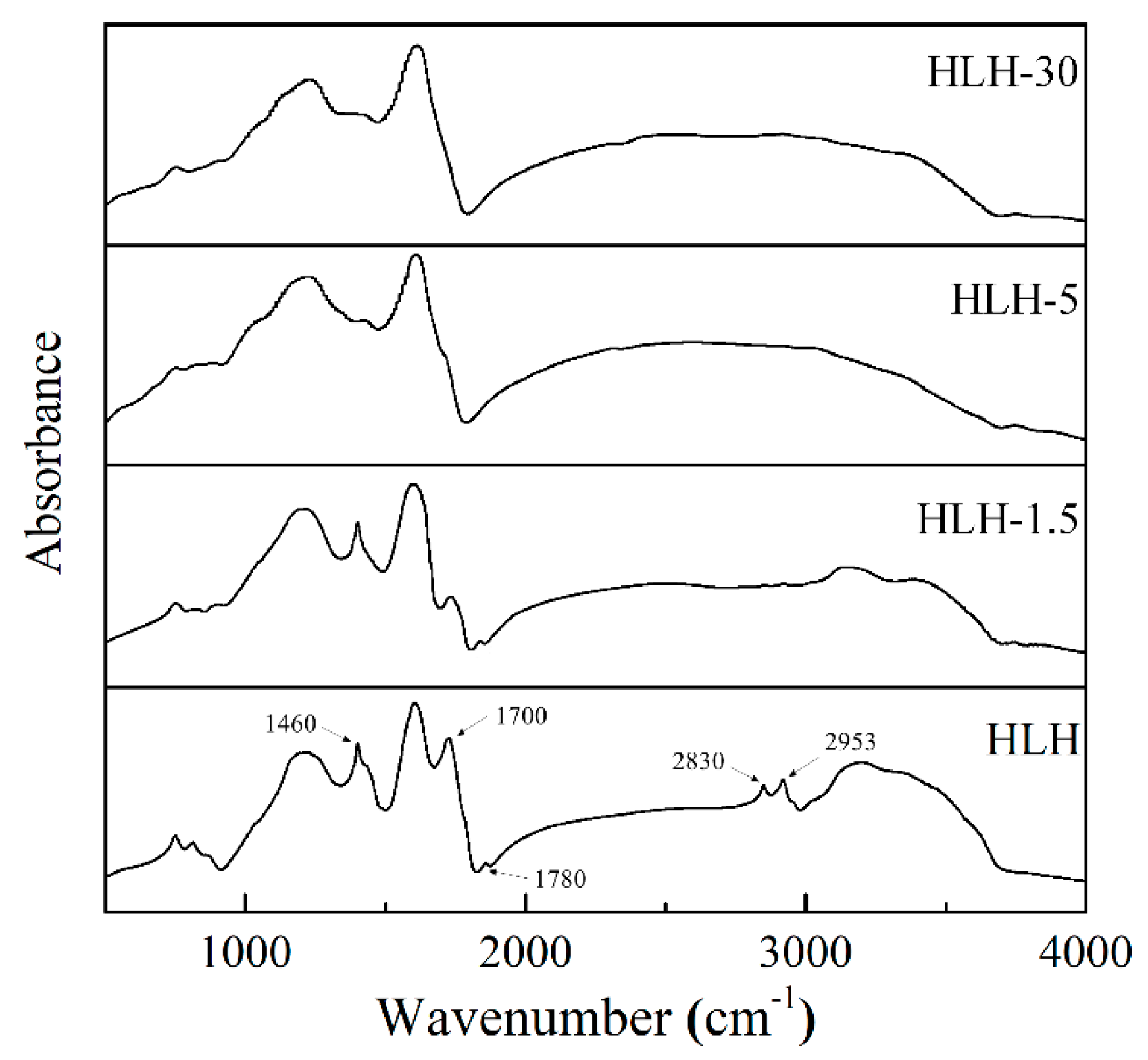
3.1. Chemical Structure Analysis by FTIR

The FTIR spectra of treated samples with different microwave radiation times is shown in Figure 1. First, some obvious bands at approximately 1460, 2830, 2953, 1700, and 1780 cm−1 can be found in HLH, implying that it contains a large number of the aliphatic groups and the oxygen-containing functional groups. Then, the gradual disappearance of the aliphatic bands with the increase in the time of microwave treatment indicates the gradual removal of the aliphatic structures. Alternatively, some cross-linked bonds, such as methylene groups, that are used to connect aromatic rings and side chains, such as methylene and methyl groups, that are attached to aromatic rings are all attributed to the aliphatic structure in low-rank coal [32]. Therefore, the fragmentation and decomposition of the aliphatic structure during microwave irradiation will likely result in the rearrangement of carbon framework in the subsequent preparation process.
According to the changes of oxygen-containing functional groups bands (1700 and 1780 cm−1) in HLH-1.5, HLH-5, HLH-30, the amount of oxygen-containing functional groups also decreased gradually with the increase in the time of microwave treatment. However, to systematically study information related to changes in oxygen-containing structures, a quantitative assessment was performed by the curve-fitted bands in the range from 1000 to 1800 cm−1 zone, according to the previous literature [33,34], and the detailed relationships of these parameters can be expressed as follows:
C=O/Car = 1780 − 1650 cm−1 zone/1605 cm−1 band,
COOH/Car = 1700 cm−1 zone/1605 cm−1 band
C–O/Car = 1260 − 1030 cm−1 zone/1605 cm−1 band.
In the above equations, C=O structures contain carboxylic acids, carbonyl acids and aryl esters, and so on, C–O–R structures can often be expressed as aryl ethers and hydroxyls, and Car is related to aromatic structure in the carbon framework. The specific results of treated samples under different is shown in Table 2.
Large quantities of oxygen functional groups can be found in HLH, but there was an obvious decrease in HLH-1.5, implying the directional removal of the low thermal stability groups (mainly as carboxylic acids and other C–O structures) at the beginning of the pretreatment with microwave irradiation. These changes are consistent with the apparent weakness of carbonyl acids at near 1660 cm−1 and aryl esters around 1775 cm−1 in FTIR spectra for HLH-1.5. The parameters continued to decrease for HLH-5 and HLH-30 with the increase in the time of microwave treatment. The quantity of COOH in HLH-1.5 showed a clear decrease, but there were rapid decreases in all the oxygen-containing groups in HLH-5, indicating the gradual removal of oxygen functional groups from low to high thermal stability with the microwave heating time. Furthermore, the slow decrease of all the parameters for HLH-30 indicated that, with a longer microwave heating time (30 min), it is difficult to further remove the oxygen functional groups with high thermal stabilities. From the above analysis, we found that HLH-5 was the most suitable sample for the subsequent preparation of AC.

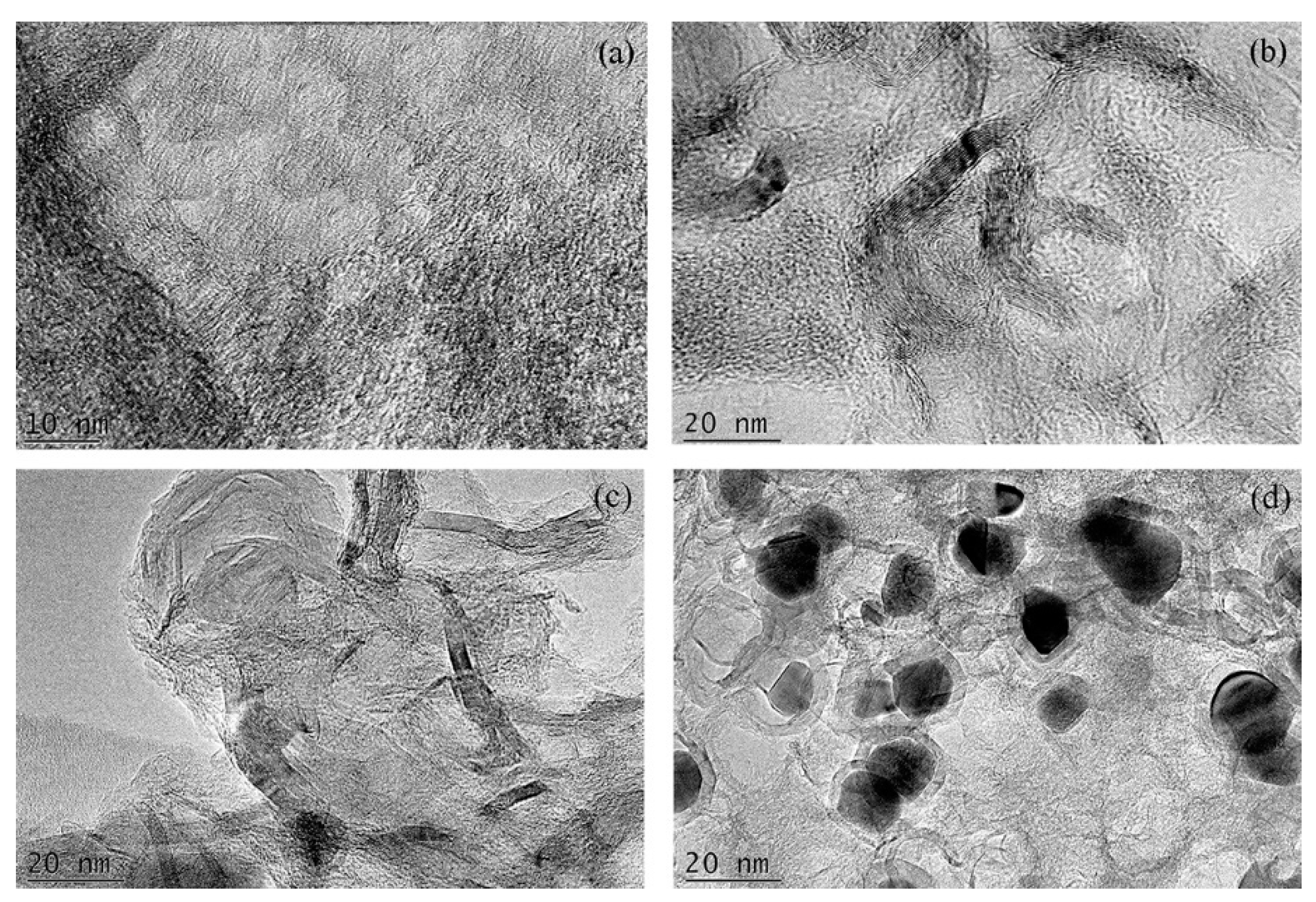
3.2. Microstructure Analysis by TEM

Several high-resolution TEM images of C-HLH-5, C-1FeHLH-5, C-2FeHLH-5, and C-3FeHLH-5 are shown in Figure 2. An abundance of amorphous regions was found, and the amorphous carbon and crystallite layers were intricately arranged in C-HLH-5 (Figure 2a). Moreover, there were more interlaced arrangements of crystallite layers in a small number of FeCl3 (10–30 wt%) in C-1FeHLH-5, C-2FeHLH-5, and C-3FeHLH-5 (Figure 2b–d). These phenomena indicated a clear increase in highly ordered crystallite layers with the increase in the amounts of FeCl3 additive during pyrolysis. The additive gradually began to move within the samples as the amount of FeCl3 increased, during which the amorphous carbon was rapidly converted to graphitized carbon via the mechanism of metal-catalyzed graphitization [20]. Remarkably, the round-like particles surrounded by long parallel-aligned multilayer graphitic microcrystals can be seen for C-3FeHLH-5 in Figure 2d. This phenomenon indicated that the additive gradually begins to blend with itself with an increase in loading amount, which leads to the formation of iron-based particles during pyrolysis. In addition, other microcrystal layers at a remote distance away from these carbon-coated iron particles were also found. In a previous study [25], we found more interlaced arrangements between amorphous carbon and crystallite layers and more morphous regions in oxidized chars, even when the Fe-based catalyst was loaded, indicating that the Fe-based catalyst can be fixed by oxygen functional groups. In other words, the free movement of the FeCl3 additive within the samples after the microwave pretreatment can further play a catalytic graphitization role in the formation of multilayer highly ordered graphitic microcrystals.

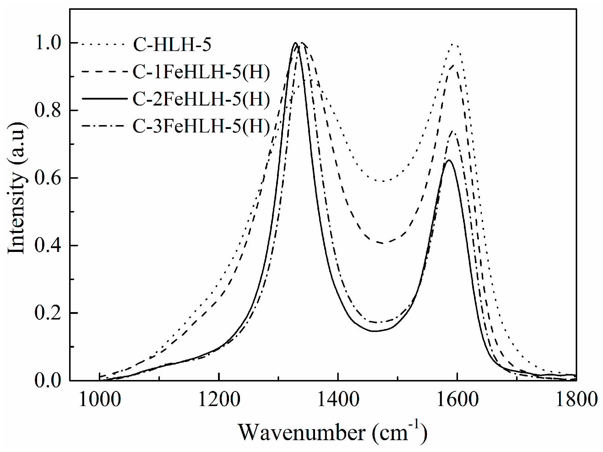
3.3. Hybrid Carbon Structure Analysis by Raman

The Raman spectra of C-HLH-5, C-1FeHLH-5(H), C-2FeHLH-5(H), and C-3FeHLH-5(H) are shown in Figure 3. To obtain more information about the hybrid carbon structure of samples, each Raman spectrum was treated further into five band areas by the fitting method [35]. Importantly, the ratios of the different band areas, such as AD1/AG, AD3/AG, AD4/AG, and AD1/AD3, represent the different types of hybrid carbon, and the specific information is listed in the previous literature [36,37]. The results of the hybrid carbon structure in carbonized chars with different amounts of FeCl3 are shown in Table 3.
The AD1/AG, AD3/AG, and AD4/AG values of C-HLH-5 reached the maximum, whereas the AD1/AD3 value reached the minimum compared to that of other samples, indicating the presence of a disordered material with a higher reactivity. Then, the AD1/AG, AD3/AG, and AD4/AG values of C-1FeHLH-5(H) and C-2FeHLH-5(H) decreased, whereas the AD1/AD3 value increased, presenting the formation of ordered materials with low reactivities as the amount of FeCl3 additive increases. However, we found that samples supported by Fe-based catalysts presented the non-graphitization tendency in the existence of oxygen functional groups during pyrolysis [25]. Therefore, the existence or removal of oxygen functional groups plays an important role on the different catalytic characteristics. In the pyrolysis stage, the Fe-based components first facilitated the decomposition of the basic unit structure, leading to the conversion of the isolated and defective sp2 structure (D1 peak) into the amorphous carbon (D3 peak). Then, this amorphous carbon was released as volatile matter by thermal cracking, but more are converted into the crystalline sp2 structure (G peak) rapidly rather than the defective sp2 structure when the oxygen functional groups have decomposed. In addition, the clear decrease in the crosslinking density (D4 peak) of the samples supported by the Fe-based catalysts was responsible for the removal of oxygen functional groups linked with the carbon matrix via microwave treatment. Furthermore, the formation of new cross-linking bonds was also severely destroyed by the movement of iron atoms within the samples in the absence of oxygen functional groups. These changes also helped the graphitization tendency of the samples. Remarkably, the abrupt changes in all four parameters for C-3FeHLH-5(H), with respect to those of C-2FeHLH-5(H), indicated its relatively slow graphitization conversion. From the result of TEM in Figure 2d, the formation of iron-based spherical particles, due to the rapid amalgamation of Fe-based catalysts, can hinder the free movement of catalysts within samples. Therefore, C-3FeHLH-5(H) with FeCl3 (30 wt%) is insufficient to further enhance the graphitization tendency of C-3FeHLH-5(H).

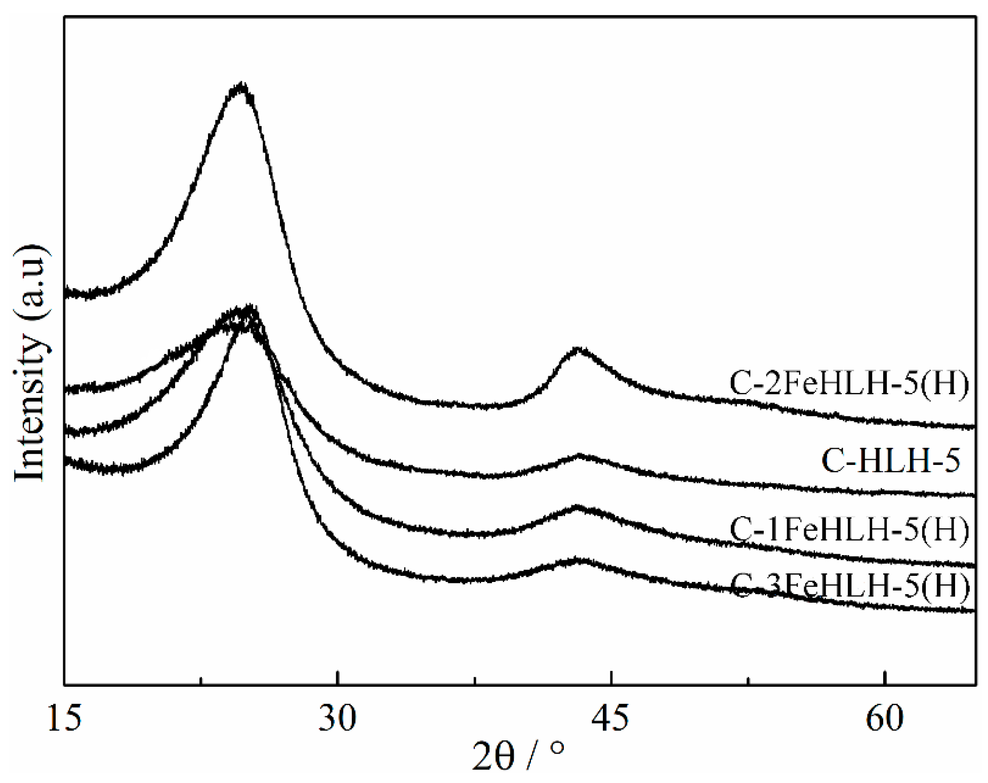
3.4. Crystal Structure Analysis by XRD

The XRD profiles of C-HLH-5, C-1FeHLH-5(H), C-2FeHLH-5(H), and C-3FeHLH-5(H) are shown in Figure 4. According to the previous literature [38], each XRD profile is treated further into two band areas by the fitting method to obtain some important structural feature information of the aromatic layers (for instance, layer distance (d002), stacking height (Lc), width (La), and layer number (N = Lc/d002)). The result of the aromatic layers in carbonized chars with different amounts of FeCl3 is shown in Table 4.
C-HLH-5 yielded a smoother curve than that of the other samples, with respect to the (002) and (100) peaks in particular; the d002 value reached a maximum of 3.55 Å, and the Lc and La values reached the minimum of 12.33 Å and 23.66 Å. The microcrystalline structure of C-HLH-5 is presented as a type of disordered structure. Even when the raw materials (HLH) are pretreated by microwave irradiation, the conversion of the disordered arrangement and small-size of microcrystals of HLH into a graphite-like structure is very difficult at low temperatures (<1000 °C) without the addition of an FeCl3 catalyst. Then, the La, Lc, and N values of C-1FeHLH-5(H) and C-2FeHLH-5(H) increased, and the d002 value decreased; this result indicated that the crystalline of HLH was converted into a highly ordered structure at low temperatures in the presence of the FeCl3 catalyst. Quite evidently, when the changes to the parameters of C-3FeHLH-5(H) with FeCl3 additive were reduced, this indicated that the rapid increase in the highly ordered structure cannot be further enhanced. The above results showed that a suitable dispersion and mobility of catalysts may enable the catalyst to penetrate to the carbon framework and develop its catalytic characteristics. However, our previous results found that Fe-based compounds presented the non-graphitization catalytic characteristics in the existence of oxygen-containing functional groups [25]. These results are related to the competition between the catalytic cracking characteristics and catalytic graphitization characteristics of the FeCl3 additive in the presence or absence of oxygen functional groups. Fe-based compounds promote the decomposition of aromatic structure to form more free radicals at the beginning of pyrolysis, highlighting their catalytic cracking characteristics. Then, due to the decomposition of oxygen-containing functional groups during microwave irradiation stage, the Fe-based compounds further facilitate the condensation of free radicals to form an ordered microstructure at a later stage of pyrolysis. Thus, the microwave pretreatment played a more important role in promoting the catalytic graphitization via FeCl3 than in sustaining catalytic cracking during pyrolysis.

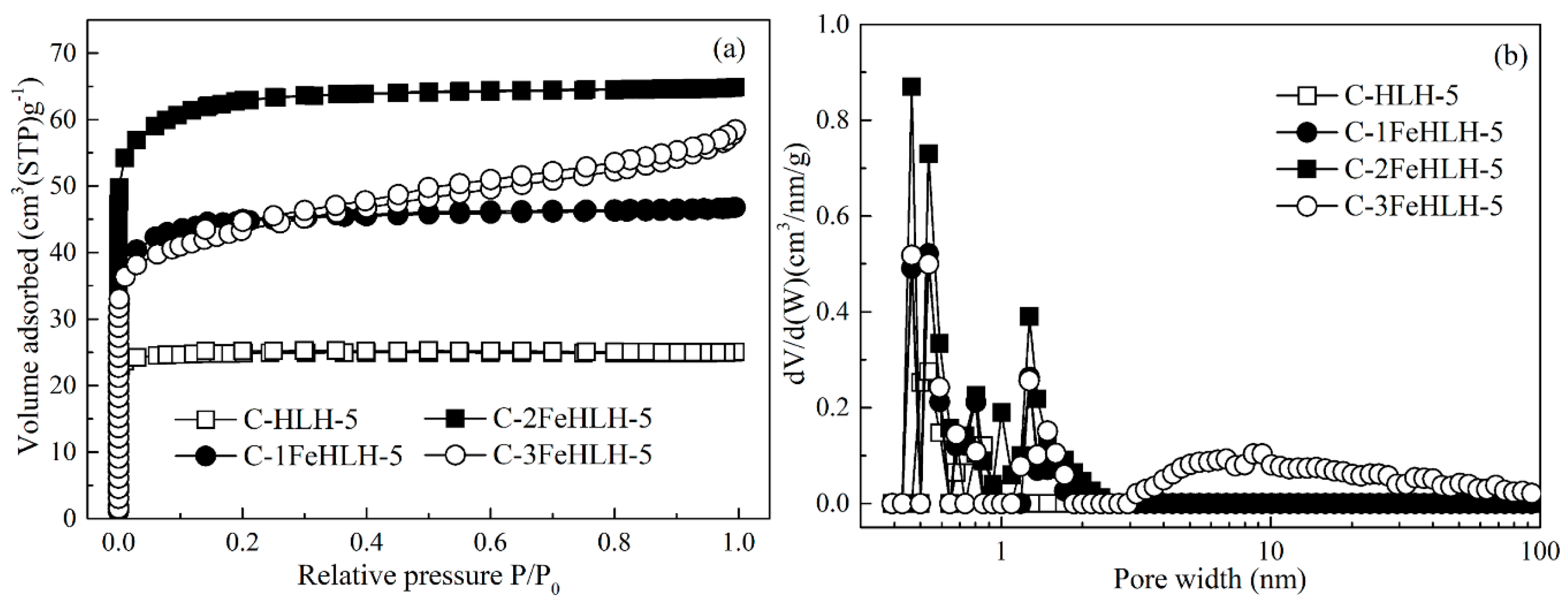
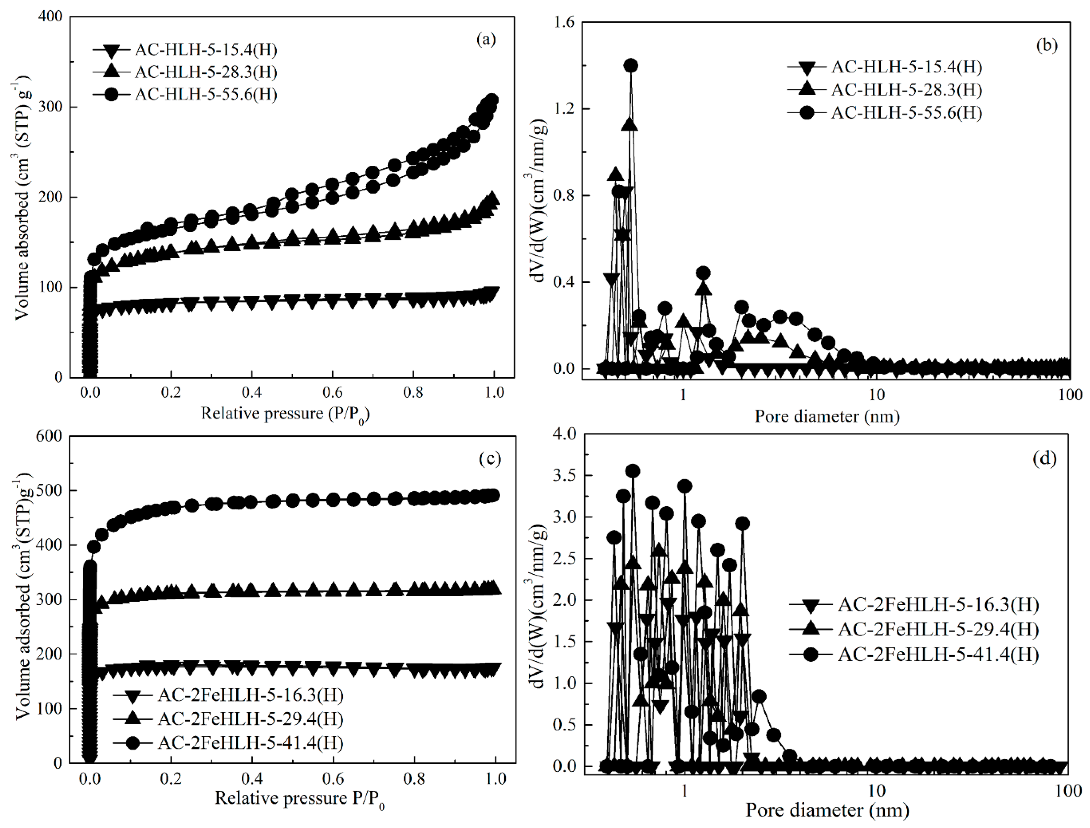
3.5. Pore Structure Analysis of the Nitrogen Adsorption Method

The results of the pore structure analysis using the nitrogen adsorption method for C-HLH-5, C-1FeHLH-5(H), C-2FeHLH-5(H), and C-3FeHLH-5(H) are shown in Figure 5. The N2 adsorption isotherms of C-HLH-5, C-1FeHLH-5(H), and C-2FeHLH-5(H) are all related to a type I, and their isotherms always remain level as the relative pressures increased. The N2 adsorption capacity of C-HLH-5 at low pressures is very small, and its size distribution is relatively narrow (0–1 nm), presenting a microporous material with a low pore volume. The N2 adsorption capacities of C-1FeHLH-5(H) and C-2FeHLH-5(H) at low pressures increased evidently, and their knees became broader. There was a clear increase in the size range from 0 to 2 nm and the corresponding pore volume, presenting a microporous material with a relative high pore volume. The increase in micropores is related to the catalytic cracking characteristics of FeCl3. Gong et al [29] found that the cleavage of the microcrystalline structure occurred with the increase in Fe-based catalysts to release more volatile matter, thus, resulting in the formation of more micropores. Alternatively, the adsorption isotherm of C-3FeHLH-5(H) is related to a type I and IV at different pressures. This isotherm begins to branch and present a hysteresis loop with the increase in relative pressure, indicating the appearance of micropore and mesopore. It is worth noting that the increase in micropores and part of mesopores (2–5 nm) is caused by the concentration and amalgamation of the FeCl3 catalyst during pyrolysis, but the formation of another part of the mesopores (5–20 nm) is related to the removal of the iron-based particles after the process of acid treatment, owing to their consistent size, as shown in Figure 2d. Therefore, a more significant increase in mesopores was found in C-3FeHLH-5(H) rather than in micropores.

3.6. Pore Structure Development of Typical Chars during Activation

Based on the above physicochemical structure analysis during pyrolysis, C-2FeHLH-5 was used as an ideal precursor for subsequent activation, owing to its highly ordered carbon structure, abundant initial micropores, and more-dispersed distribution of Fe-catalysts; C-HLH-5 was used as the contrastive precursor. Therefore, the pore development of C-HLH-5 and C-2FeHLH-5, used as the typical chars during activation, can be analyzed in detail, and the results of the pore structure analysis using the nitrogen adsorption method is shown in Figure 5 and Figure 6.
First, the isotherm of AC-HLH-5-15.4(H) was clearly of type I, presenting a narrow pore-size distribution (0–1 nm). Furthermore, an SBET value of 103.63 m2∙g−1, Vmic value of 0.059 m3∙g−1, and non-Vmic value of 4.84% for AC-HLH-5-15.4(H) were obtained, showing the microporous structure. At the beginning of activation, the initial pores of C-HLH-5 helped the diffusion of activated gas into the interior of the particle, which strengthened the etching of the carbon-based framework by activated gas, thus resulting in an increase in the microporous structure. With the continued development of the activation process, the N2 isotherms of AC-HLH-5-28.3(H) and AC-HLH-5-55.6(H) all became steep with increasing relative pressure, and clear hysteresis loops were observed, showing the characteristics of type I and IV at different pressures. A gradual increase in micropores and the rapid formation and development of more mesopores (2–8 nm) were also found, as shown in Figure 6b. Moreover, the changes in the pore structure parameters of AC-HLH-5-28.3(H) and AC-HLH-5-55.6(H) also indicated an enlargement of the micropores into mesopores and the production of some new micropores. Remarkably, the rapid increase in the non-Vmic value indicated the more apparent development of mesopores rather than that of new micropores, which is related to the continuous removal of the active sites with the increase in burn-off. According to Figure S3a, the ordering degree of AC-HLH-5 first decreased rapidly and then increased gradually during activation. Finally, a low SBET value of 666.25 m2 g−1 for AC-HLH-5-55.6(H) was obtained.
The N2 adsorption isotherms of AC-2FeHLH-5-16.3(H), AC-2FeHLH-5-29.4(H), and AC-2FeHLH-5-41.4(H) were all of type I, and a clear increase in the isotherm capacities at a low pressure can be found with an increase in burn-off. The rapid increase in Vt, Vmic, and SBET values, and no evident change in the non-Vmic value for AC-2FeHLH-5-16.3(H), AC-2FeHLH-5-29.4(H), and AC-2FeHLH-5-41.4(H) during the whole stage of activation are shown in Table 5, revealing a sustained production of additional micropores. It can be inferred that the presence of metal catalyst can change the reaction pathways between the carbon structure and activated gas [39]. More concretely, the active sites could no longer be preferentially consumed with activated gas, and some intermediates were formed first in the presence of catalysts, and then, these intermediates could react with a gasifying agent to strengthen the sustained etching of the carbon-based framework. According to Figure S3b, the ordering degree of AC-2FeHLH-5 continually increased with the amount of burn-off. Finally, AC-2FeHLH-5-41.4(H) with the high SBET value (1852.43 m2 g−1) at a relatively low burn-off values of 41.4% was obtained.

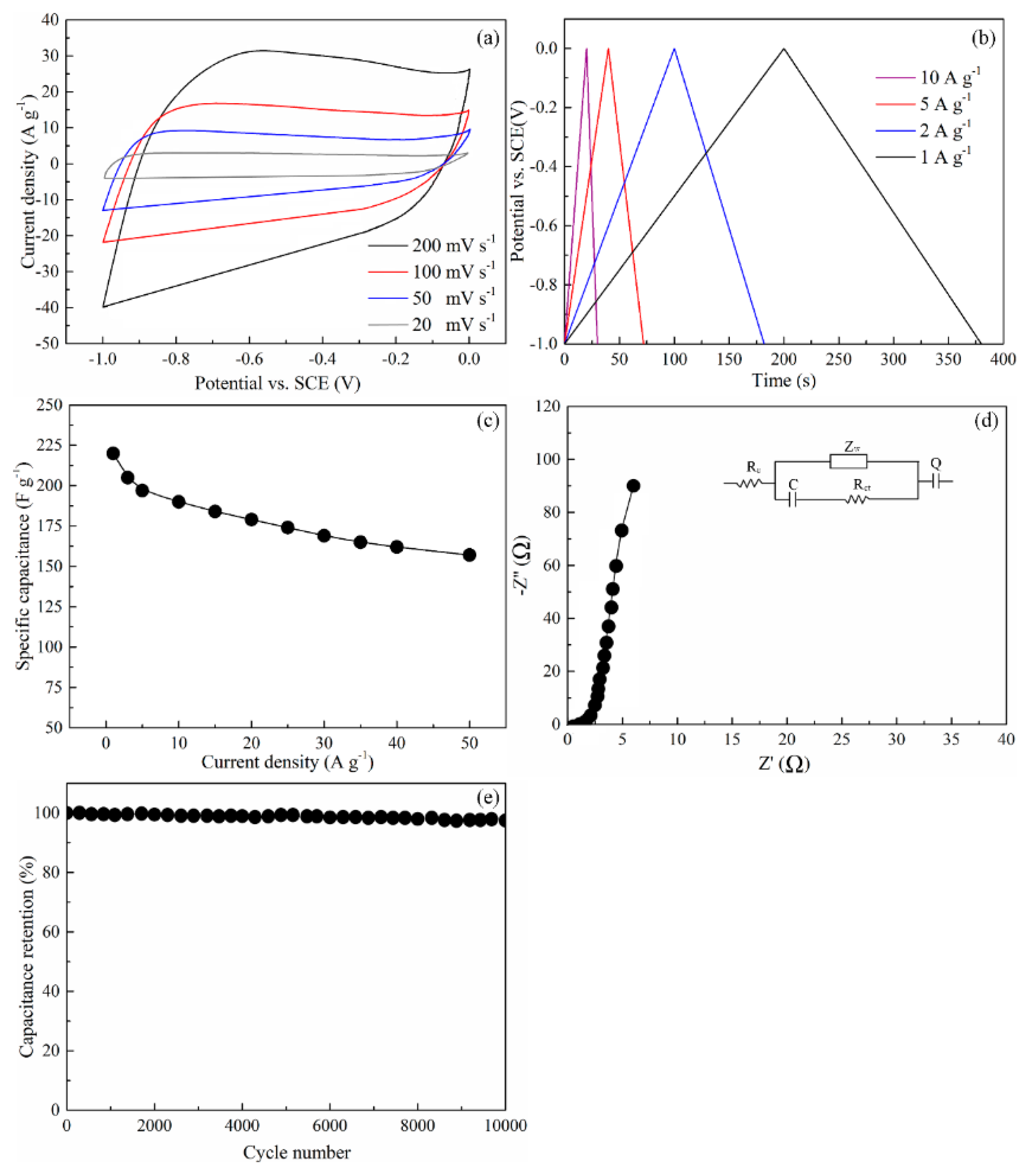
3.7. Electrochemical Measurements

AC-2FeHLH-5-41.4(H) was used an ideal supercapacitor electrode material, owing to its the highly ordered microstructure and high SBET. The results of the electrochemical experiment with AC-2FeHLH-5-41.4(H) are shown in Figure 7. To identify the advantages of AC-2FeHLH-5-41.4(H) obtained by the new method in this research, we also compared the super-capacitive performances of various activated carbons in the previous publications from bamboo stalk, using K2FeO4 (denoted as PGBC) [40], and low-rank coals, with the addition of FeCl3 (denoted as MI-AC-2) and without the addition of FeCl3 (denoted as AC) [41].
The CV curves of AC-2FeHLH-5-41.4(H) electrode always presented a quasi-rectangular shape with the increase in scan rate from 20 mV s−1 to 200 mV s−1, as seen in Figure 7a, but distorted CV curves of the AC electrode and the smaller current density for PGBC and MI-AC-2 were found in previous publications [40,41], indicating a fast charge transport in AC-2FeHLH-5-41.4(H). In addition, compared with the AC electrode [41], the perfect isosceles triangle shapes of AC-2FeHLH-5-41.4(H) at different current densities can be seen in Figure 7b, indicating excellent charge and discharge qualities in terms of an electric double layer capacitor (EDLC). As shown in Figure 7c, the AC-2FeHLH-5-41.4(H) electrode had much higher specific capacitances (224 F g−1 at 1 A g−1) than that of PGBC (40 F g−1 at 1 A g−1), MI-AC-2(211 F g−1 at 1 A g−1), and AC (115 F g−1 at 1 A g−1). [40,41] With the increase of current densities, AC-2FeHLH-5-41.4(H) always retained high values (170 F g−1 at 30 A g−1), rather than an obvious capacitance decay for PGBC (25 F g−1 at 30 A g−1), MI-AC-2 (160 F g−1 at 30 A g−1), and AC (45 F g−1 at 30 A g−1). [40,41] This result also showed an excellent charge-discharge capability performance for the AC-2FeHLH-5-41.4(H) electrode. Furthermore, the kinetics of the electrochemical reaction was studied by EIS. The result of the Nyquist plots for the AC-2FeHLH-5-41.4(H) electrode, in the frequency range from 10 mHz to 100 KHz, is given in Figure 7d. There were clear impedance loops for AC-2FeHLH-5-41.4(H) with a relatively small semicircle radius in the high frequency region relative to a lower slope of AC in the previous publications [41], indicating a small charge transfer resistance. Then, the fitting equivalent circuit model was obtained by the coupled nonlinear Schrodinger equation (CNLS) method, as shown in Figure 7d. There was a high slope in the low-frequency region for AC-2FeHLH-5-41.4(H) with a low resistance of 0.3511 Ω, showing a good ion transport dynamic. The result of the cycling stability test for AC-2FeHLH-5-41.4(H) electrode at a current density of 5 A g−1 is shown in Figure 7e. The AC-2FeHLH-5-41.4(H) electrode kept about 96% of the capacitance after 10,000 cycles at a current density of 5 A g−1, rather than an obvious reduction of PGBC (84%) [40] at 5000 cycles and AC (85%) at 10,000 cycles [41]. Therefore, AC-2FeHLH-5-41.4(H) presented an even greater cycling stability.

4. Conclusions

Low-rank coals (HLH) were successfully converted to highly porous graphitic activated carbons (HPGACs) with a microwave pretreatment, a melt infiltration of FeCl3 into the carbon framework during pyrolysis at 900 °C, and the subsequent CO2-assisted physical activation. The key of graphitization conversion at low temperature is that the dispersed and mobile iron species, in the absence of oxygen functional group via the microwave pretreatment, can further play a catalytic graphitization role during which sp3 carbon atoms are consumed and converted into the crystalline sp2 structure. Subsequently, the highly dispersed iron species also play an important role as activating catalysts to greatly facilitate the development of micropores. In the case of similar burn-out rates, the SBET of 1852.43 m2∙g−1 of AC-2FeHLH-5-41.4(H) is much larger than that of AC-HLH-5-55.6(H), obtained solely by physical activation. Compared with other supercapacitor electrode materials from various low-cost resources (coal/biomass) in the previous publications, such a well-developed pore structure and highly ordered graphene lattice endow AC-2FeHLH-5-41.4(H) with a low defect density, the high purity and SBET presents a good super-capacitive performance, including high capacitance, good rate capability, and excellent cycling stability.

Supplementary Materials

The following are available online at https://www.mdpi.com/2227-9717/7/5/300/s1, Figure S1: XRD profiles of the (a) raw Huolinhe lignite and (b) demineralized sample, Figure S2: XRD phase analysis of C-1FeHLH-5 and C-1FeHLH-5(H), Figure S3: XRD profiles from different AC during activation.

Author Contributions

D.L., S.L. and L.D. conceived and designed the experiments; X.Z., R.S. and Z.H. carried out the experiments; D.L. wrote the paper; D.L. and B.J. reviewed the paper.

Funding

This research was funded by National Natural Science Foundation of China, grant number 51806080, and Scientific Research Fund Project of Jilin Agricultural University, grant number 201801, and Jilin Province Education Department Science and Technology Program during the Thirteenth Five-year Plan Period, grant number JJKH20190940KJ.

Conflicts of Interest

The authors declare no conflict of interest.

References

  1. Tarascon, J.M.; Armand, M. Issues and challenges facing rechargeable lithium batteries. Nature 2001, 414, 359–367. [Google Scholar] [CrossRef] [PubMed]
  2. Peng, X.; Peng, L.L.; Wu, C.Z.; Xie, Y. Two dimensional nanomaterials for flexible supercapacitors. Chem. Soc. Rev. 2014, 43, 3303–3323. [Google Scholar] [CrossRef]
  3. Wang, D.W.; Li, F.; Liu, M.; Lu, G.Q.; Cheng, H.M. 3D aperiodic hierarchical porous graphitic carbon material for high-rate electrochemical capacitive energy storage. Angew. Chem. Int. Ed. 2008, 47, 373–376. [Google Scholar] [CrossRef]
  4. Ma, F.W.; Ma, D.; Wu, G.; Geng, W.D.; Shao, J.Q.; Song, S.J.; Wan, J.F.; Qiu, J.S. Construction of 3D nano-structure hierarchical porous graphitic carbons by charge-induced self-assembly and nanocrystal assisted catalytic graphitization for supercapacitors. Chem. Commun. 2016, 52, 6673–6676. [Google Scholar] [CrossRef]
  5. Liu, S.Q.; Zhang, Y.J.; Tuo, K.Y.; Wang, L.P.; Chen, G. Structure, electrical conductivity, and dielectric properties of semi-coke derived from microwave-pyrolyzed low-rank coal. Fuel Process. Technol. 2018, 178, 139–147. [Google Scholar] [CrossRef]
  6. Wang, Q.; Nie, Y.F.; Chen, X.Y.; Xiao, Z.H.; Zhang, Z.J. Controllable synthesis of 2D amorphous carbon and partially graphitic carbon materials: Large improvement of electrochemical performance by the redox additive of sulfanilic acid azochromotrop in KOH electrolyte. Electrochim. Acta 2016, 200, 247–258. [Google Scholar] [CrossRef]
  7. Zhu, Y.W.; Gao, J.H.; Li, Y. Preparation of activated carbons for SO2, adsorption by CO2, and steam activation. J. Taiwan Inst. Chem. Eng. 2012, 43, 112–119. [Google Scholar] [CrossRef]
  8. Zhu, Y.W.; Gao, J.H.; Li, Y.; Sun, F.; Qin, Y.K. Preparation and characterization of activated carbons for SO2 adsorption from taixi anthracite by physical activation with steam. Korean J. Chem. Eng. 2011, 28, 2344–2350. [Google Scholar] [CrossRef]
  9. San, M.G.; Fowler, G.D.; Sollars, C.J. A study of the characteristics of activated carbons produced by steam and carbon dioxide activation of waste tyre rubber. Carbon 2003, 41, 1009–1061. [Google Scholar]
  10. Wang, K.; Cao, Y.; Wang, X. Nickel catalytic graphitized porous carbon as electrode material for high performance supercapacitors. Energy 2016, 101, 9–15. [Google Scholar] [CrossRef] [Green Version]
  11. He, X.J.; Zhang, H.B.; Zhang, H. Direct synthesis of 3D hollow porous graphene balls from coal tar pitch for high performance supercapacitors. J. Mater. Chem. A 2014, 46, 19633–19640. [Google Scholar] [CrossRef]
  12. Li, Y.T.; Pi, Y.T.; Lu, L.M. Hierarchical porous active carbon from fallen leaves by synergy of K2CO3, and their supercapacitor performance. J. Power Sources 2015, 299, 519–528. [Google Scholar] [CrossRef]
  13. Foo, K.Y.; Hameed, B.H. Preparation and characterization of activated carbon from sunflower seed oil residue via microwave assisted K2CO3 activation. Bioresour. Technol. 2010, 102, 9794–9799. [Google Scholar] [CrossRef]
  14. Ma, G.F.; Yang, Q.; Sun, K.J. Nitrogen-doped porous carbon derived from biomass waste for high-performance supercapacitor. Bioresour. Technol. 2015, 197, 137–142. [Google Scholar] [CrossRef]
  15. Elmouwahidi, A.; Bailón-García, E.; Pérez-Cadenas, A.F. Activated carbons from KOH and H3PO4-activation of olive residues and its application as supercapacitor electrodes. Electrochim. Acta 2017, 229, 219–228. [Google Scholar] [CrossRef]
  16. SeVilla, M.; Sanchís, C.; Valdés-Solís, T.; Morallõn, E.; Fuertes, A.B. Direct synthesis of graphitic carbon nanostructures from saccharides and their use as electrocatalytic supports. Carbon 2008, 46, 931–939. [Google Scholar] [CrossRef] [Green Version]
  17. Ōya, A.; Marsh, H. Phenomena of catalytic graphitization. J. Mater. Sci. 1982, 17, 309–322. [Google Scholar] [CrossRef]
  18. Li, S.; Tian, C.G.; Li, M.T.; Meng, X.Y.; Wang, L.; Wang, R.H.; Yin, J.; Fu, H.G. From coconut shell to porous graphene-like nanosheets for high-power supercapacitors. J. Mater. Chem. A 2013, 1, 6462–6470. [Google Scholar]
  19. Ohtsuka, Y.; Xu, C.; Kong, D.; Tsubouchi, N. Decomposition of ammonia with iron and calcium catakysts supported on coal chars. Fuel 2004, 83, 685–692. [Google Scholar] [CrossRef]
  20. Mori, H.; Asmi, A.K.; Ohtsuka, Y. Role of iron catalyst in fate of fuel nitrogen during coal pyrolysis. Energy Fuel 1996, 10, 1022–1027. [Google Scholar] [CrossRef]
  21. Yu, Z.L.; Xin, S.; You, Y.; Yu, L.; Lin, Y.; Xu, D.W.; Qiao, C.; Huang, Z.H.; Yang, N.; Yu, S.H.; et al. Ion-catalyzed synthesis of microporous hard carbon embedded with expanded nanographite for enhanced lithium/sodium storage. J. Am. Chem. Soc. 2016, 138, 14915–14922. [Google Scholar] [CrossRef]
  22. Tahmasebi, A.; Yu, J.L.; Han, Y.N.; Li, X.C. A study of chemical structure changes of Chinese lignite during fluidized-bed drying in nitrogen and air. Fuel Process. Technol. 2012, 101, 85–93. [Google Scholar] [CrossRef]
  23. Aida, T. Reliable chemical determination of oxygen-containing functionalities in coal and coal products. Carboxylic acid and phenolic hydroxyl functionalities. Fuel Energy Abstr. 1996, 37, 411. [Google Scholar]
  24. Liu, D.D.; Gao, J.H.; Cao, Q.X.; Wu, S.H.; Qin, Y.K. Improvement of activated carbon from Jixi bituminous coal by air preoxidation. Energy Fuel 2017, 31, 1406–1415. [Google Scholar] [CrossRef]
  25. Liu, D.D.; Jia, B.Y.; Liu, X.J.; Zhao, B.J.; Gao, J.H.; Cao, Q.X.; Wu, S.H.; Qin, Y.K. Effects of oxygen functional groups and FeCl3 on the evolution of physico-chemical structure in activated carbon obtained from Jixi bituminous coal. RSC Adv. 2018, 8, 8569–8579. [Google Scholar] [CrossRef]
  26. Menéndez, J.A.; Arenillas, A.; Fidalgo, B.; Fernández, Y.; Zubizarreta, L.; Calvo, E.G.; Bermúdez, J.M. Microwave heating processes involving carbon materials. Fuel Process. Technol. 2010, 91, 1–8. [Google Scholar] [CrossRef] [Green Version]
  27. Menéndez, J.A.; Menéndez, E.M.; Iglesias, M.J.; García, A.; Pis, J.J. Modification of the surface chemistry of active carbons by means of microwave-induced treatments. Carbon 1999, 37, 1115–1121. [Google Scholar] [CrossRef]
  28. Valente Nabais, J.M.; Carrott, P.J.M.; Ribeiro Carrott, M.M.L.; Menéndez, J.A. Preparation and modification of activated carbon fibres by microwave heating. Carbon 2004, 42, 1315–1320. [Google Scholar] [CrossRef]
  29. Gong, X.Z.; Guo, Z.C.; Wang, Z. Variation of char structure during anthracite pyrolysis catalyzed by Fe2O3 and its influence on char combustion reactivity. Energy Fuels 2009, 23, 4547–4552. [Google Scholar] [CrossRef]
  30. Yang, K.B.; Peng, J.H.; Xia, H.Y.; Zhang, L.B.; Srinivasakannan, C.; Guo, S.H. Textural characteristics of activated carbon by single step CO2 activation from coconut shells. J. Taiwan Inst. Chem. Eng. 2010, 41, 367–372. [Google Scholar] [CrossRef]
  31. Pietrzak, R. XPS study and physico-chemical properties of nitrogen-enriched microporous activated carbon from high volatile bituminous coal. Fuel 2009, 88, 1871–1877. [Google Scholar] [CrossRef]
  32. Nomura, S.; Thomas, K.M. Fundamental aspects of coal structural changes in the thermoplastic phase. Fuel 1998, 77, 829–836. [Google Scholar] [CrossRef]
  33. Meng, F.R.; Yu, J.L.; Tahmasebi, A.; Han, Y.N.; Zhao, H.; Lucas, J. Characteristics of chars from low-temperature pyrolysis of lignite. Energy Fuels 2014, 28, 275–284. [Google Scholar] [CrossRef]
  34. Ibarra, J.; Muñoz, E.; Moliner, R. FTIR study of the evolution of coal structure during the coaification process. Org. Geochem. 1996, 24, 725–735. [Google Scholar] [CrossRef]
  35. Li, T.; Zhang, L.; Li, D. Effects of gasification atmosphere and temperature on char structural evolution during the gasification of collie sub-bituminous coal. Fuel 2014, 117, 1190–1195. [Google Scholar] [CrossRef]
  36. Sasezky, A.; Muckenhuber, H.; Grothe, H. Raman microspectroscopy of soot and related carbonaceous materials: Spectral analysis and structural information. Carbon 2005, 43, 1731–1742. [Google Scholar] [CrossRef]
  37. Wu, D.; Liu, G.; Chen, S.; Sun, R. An experimental investigation on heating rate effect in the thermal behavior of perhydrous bituminous coal during pyrolysis. J. Therm. Anal. Calorim. 2015, 119, 2195–2203. [Google Scholar] [CrossRef]
  38. Liu, D.D.; Gao, J.H.; Wu, S.H.; Qin, Y.K. Effect of char structures caused by varying the amount of FeCl3 on the pore development during activation. RSC Adv. 2016, 6, 87478–87485. [Google Scholar] [CrossRef]
  39. Wu, Y.Q.; Wang, J.J.; Wu, S.Y.; Huang, S.; Gao, J.S. Potassium-catalyzed steam gasification of petroleum coke for H2 production: Reactivity, selectivity and gas release. Fuel Process. Technol. 2011, 92, 523–530. [Google Scholar] [CrossRef]
  40. Gong, Y.N.; Li, D.L.; Luo, C.Z.; Fu, Q.; Pan, C.X. Highly porous graphitic biomass carbon as advanced electrode materials for supercapacitors. Green Chem. 2017, 19, 4132–4140. [Google Scholar] [CrossRef]
  41. Wang, L.J.; Sun, F.; Gao, J.H.; Pi, X.X.; Pei, T.; Qie, Z.P.; Zhao, G.B.; Qin, Y.K. A novel melt infiltration method promoting porosity development of low-rank coal derived activated carbon as supercapacitor electrode materials. J. Taiwan Inst. Chem. Eng. 2018, 91, 588–596. [Google Scholar] [CrossRef]
Figure 1. Fourier transform infrared spectroscopy (FTIR) spectra of pretreated samples under different irradiation times.
Processes 07 00300 g001
Figure 2. TEM images of carbonized chars with different amounts of FeCl3 additive (a) C-HLH-5, (b) C-1FeHLH-5, (c) C-2FeHLH-5, and (d) C-3FeHLH-5.
Processes 07 00300 g002
Figure 3. Raman spectra of carbonized chars with different amounts of FeCl3 additive.
Processes 07 00300 g003
Figure 4. XRD profiles of carbonized chars with different amounts of FeCl3 additive.
Processes 07 00300 g004
Figure 5. (a) N2 adsorption isotherms and (b) pore-size distributions of different chars with and/or without the additives produced by pyrolysis.
Processes 07 00300 g005
Figure 6. (a) N2 adsorption isotherms and (b) pore-size distributions of AC-HLH-5 at different burn offs during activation; (c) N2 adsorption isotherms and (d) pore-size distributions of AC-2FeHLH-5 at different burn offs during activation.
Processes 07 00300 g006
Figure 7. Electrochemical performances of AC-2FeHLH-5-41.4(H) in 6 M KOH electrolyte: (a) cyclic voltammetry curves of AC-2FeHLH-5-41.4(H) at the scan rates of 20 to 200 mV s−1; (b) galvanostatic charge-discharge curves of AC-2FeHLH-5-41.4(H) at different current densities; (c) gravimetric capacitances of AC-2FeHLH-5-41.4(H) at different current densities; (d) Nyquist plots of AC-2FeHLH-5-41.4(H) inset shows the fitting equivalent circuit model; and (e) cycling stability of AC-2FeHLH-5-41.4(H) at a current density of 5 A g−1.
Processes 07 00300 g007
Table 1. Proximate and ultimate analyses of Huolinhe lignite (wt%).
VadFCadAadMadCdafHdafOdaf *NdafSdaf
39.6639.660.123.6274.8119.494.011.310.38
ad (air-dried basis): the coal in dry air was used as a benchmark; daf (dry ash free basis): the remaining component after the removal of water and ash in coal was used as a benchmark; * By difference.
Table 2. Quantitative result of treated samples under different microwave radiation times.
HLHHLH-1.5HLH-5HLH-30
C=O/Car2.101.730.150.12
COOH/Car1.120.460.070.06
C-O/Car2.311.830.140.11
C=O structures contain carboxylic acids, carbonyl acids and aryl esters, and so on; C–O–R structures can often be expressed as aryl ethers and hydroxyls; Car is related to aromatic structure in the carbon framework.
Table 3. Parameters of hybrid carbon structure of carbonized chars with different amounts of FeCl3 additive.
C-HLH-5C-1FeHLH-5(H)C-2FeHLH-5(H)C-3FeHLH-5(H)
AD1/AG3.7632.8411.1071.245
AD3/AG2.7071.8110.5050.614
AD4/AG0.8450.7690.5180.603
AD1/AD31.3901.5682.1372.028
The value of AD1/AG represents the defect degree of the microcrystalline structure; the value of AD3/AG is related to the amorphous carbon; the value of AD4/AG represents the relative quantity of cross-linking bonds; AD1/AD3 can indicate the ratio between big rings relative to small fused rings in chars.
Table 4. XRD data of carbonized chars with different amounts of FeCl3 additive.
C-HLH-5C-1FeHLH-5(H)C-2FeHLH-5(H)C-3FeHLH-5(H)
La (Å)23.6625.7131.2828.55
Lc(Å)12.3313.1715.8514.01
d002(Å)3.553.403.143.29
N3.473.875.054.26
d002: layer distance; Lc: stacking height; La: width; N = Lc/d002: layer number.
Table 5. Pore structure parameters of typical chars at different burn offs during activation.
SamplesSBET (m2/g)Vt (m3/g)Vmic (m3/g)Non-Vmic (%)
AC-HLH-5-15.4(H)103.630.0620.0594.84
AC-HLH-5-28.3(H)321.770.1300.10122.31
AC-HLH-5-55.6(H)666.250.2010.11343.78
AC-2FeHLH-5-16.3(H)652.550.1680.1604.76
AC-2FeHLH-5-29.4(H)1048.150.2590.2455.41
AC-2FeHLH-5-41.4(H)1852.430.3780.3565.82
SBET: specific surface area; Vt: total pore volume; Vmic: micropore volume; Non-Vmic: except for micropore volume.

