Article

Application of VES Acid System on Carbonate Rocks with Uninvaded Matrix for Acid Etching and Fracture Propagation

1
State Key Laboratory of Petroleum Resources and Prospecting, China University of Petroleum (Beijing), Beijing 102249, China
2
Patent Examination Cooperation Sichuan Center of the Patent Office, Chengdu 610213, Sichuan, China
3
Xibei Oil Company Branch, SINOPEC, Urumqi 830011, Xinjiang, China
4
Industrial and Systems Engineering, Rutgers University, New Brunswick, NJ 08854, USA
*
Author to whom correspondence should be addressed.
Processes 2019, 7(3), 159; https://doi.org/10.3390/pr7030159
Submission received: 18 February 2019 / Revised: 9 March 2019 / Accepted: 11 March 2019 / Published: 15 March 2019

Abstract

:
We investigated the performance of viscoelastic surfactant (VES) solution when applied in treatment on the uninvaded matrix using core flooding tests to analyze the impact of VES/CaCl2 concentration on fluid viscosity. In this paper, core samples from Tahe carbonate reservoir, with an average permeability less than 0.02 × 10⁻³ μm−2 and a small average porosity in the range of approximately 0.04–5.24% are used in the experiments. Computed tomography (CT) scanning is used to provide a detailed description of inner structure variation of cores after the acid system treatment. The results confirmed that a large pressure difference contributed to fracture propagation and the relative permeability of water increased significantly after the treatment. It was also found that higher concentrations of VES and/or Ca2+ induced higher viscosity and a stronger fracturing effect, while a lower concentration improved the reaction rates and etching effect, generating small worm holes inside the core. Foam in-situ produced during the etching process is the major contributor to the fluid viscosity enhancement. The permeability of fracture formed on the surface of the core is more sensitive to the confining pressure. These findings can help better understand the rheological properties of the acid system and etching and fracturing mechanisms during acid treatment, and which provides instructions for field implementation.

1. Introduction

Matrix acidizing is extensively used to stimulate productivity and injectivity for carbonate reservoirs with low permeability and high heterogeneity [1]. Viscoelastic surfactant (VES) based self-diverting acid systems, with a reputation for less formation damage, are widely used to provide better matrix treatment of carbonate rocks with ultra-low permeability. During the acidizing reaction, the viscosity of the acid system rises, and targeted zones are stimulated because of the addition of salts, which changes the chargeability of the surfactant and gradually forms worm-like micelles [2]. A temporarily generated barrier across the treated zones can divert the subsequent fluid to achieve complete stimulation of all the treatment zones [3,4]. Formation hydrocarbons, or a small amount of pre-flush fluids as breaker, completely consume the surfactant gel after acid treatments. According to the core tests, it is demonstrated that the fluid properties relate to pH, surfactant and polyelectrolyte concentrations, temperatures, internal breaker loading, and salt concentrations [5]. Diversion tests are performed to evaluate the pressure response and stimulation efficiency by core-flow experiments [6,7]. Lungwitz et al. demonstrate the diverting ability of the acid as a function of permeability, characterized by introducing the concept of maximum pressure ratio (dPmax/dP0) supported by core-flow and acid conductivity tests using limestone and dolomite cores [3]. Computed tomography (CT) is another method to evaluate the performance of the self-diverting acid system, especially for characterizing the wormhole propagation expected from the acidizing process. Based on aforementioned experimental results, some researchers focused on modeling the wormhole propagation during acid treatment [8,9,10]. However, the acidizing process in the actual formation happens in pores of carbonate rocks, and these studies neglect the scale of the reaction. Experiments with matrix uninvaded cores with low permeability and under high pressure, to the best of our knowledge, are rarely reported in existing literature.
This paper mainly focuses on the performance of VES solution when applied in treatment on uninvaded matrix. First, several experiments have been conducted to discuss the impact of CaCl2 concentration, VES concentration on the rheological properties of the VES acid system. Additionally, single core flooding experiment and dual-core flooding experiments in conjunction with CT imaging were used to investigate the fracture propagation process and evaluate the diverting ability of the VES acid system. A fluid-mechanical numerical model to quantify the process and to study the reaction mechanism of the VES acid system with carbonate will be our future work.

2. Experimental Section

2.1. Materials and Apparatus

Viscoelastic surfactant (VES, a type of amphiphilic surfactant) is an industrial liquid product by combining distilled water with 10% (w/w) VES. Other substances are A.R. grade without further purification: Hydrochloride acid (HCl, 36.5 wt%, Aladdin, Shanghai, China), Sodium chloride (NaCl, Aladdin, Shanghai, China), Calcium chloride (CaCl2, Aladdin, Shanghai, China). Distilled water was used for all the experiments conducted in this work.
The experiment set-up mainly consisted of the following apparatus: Industrial X-CT with resolution of 0.02 mm (v|tome|x L 450; GE Measurement & Control, Billerica, MA, USA); Gas foam flow meter (Beijing, China); Core flow experiment (Figure 1); Rheometer (HAAKE RS-600, Vreden, Germany); Electric blast drying oven with highest heating temperature 150 °C, with error of ±1 °C (Hai-an, China). Precision balance, AY120, with an accuracy of 0.1 mg (Shimadazu, Kyoto, Japan). Electric agitator, SXJQ-1 (Tianjin, China); Vacuum pump, Piston container (V = 200, 500 mL) (Hai-an, China); Manual operated piston screw pump (Hai-an, China). Figure 1 depicts the acid fracturing system.

2.2. Experiment Design and Methods

2.2.1. Preparation of Core Samples and Acid Fluid

Carbonate cores are taken from a down-hole sample well through the core drilling. Parameters such as length and relative permeability of N2 are listed in Table 1.
The concentrations of HCl and VES in the experiments were rigorously designed according to the recommended values of field treatment to achieve identical rheological properties of acid system and reaction rate during field implementation. Experimental parameters and the core parameters are listed in Table 1.

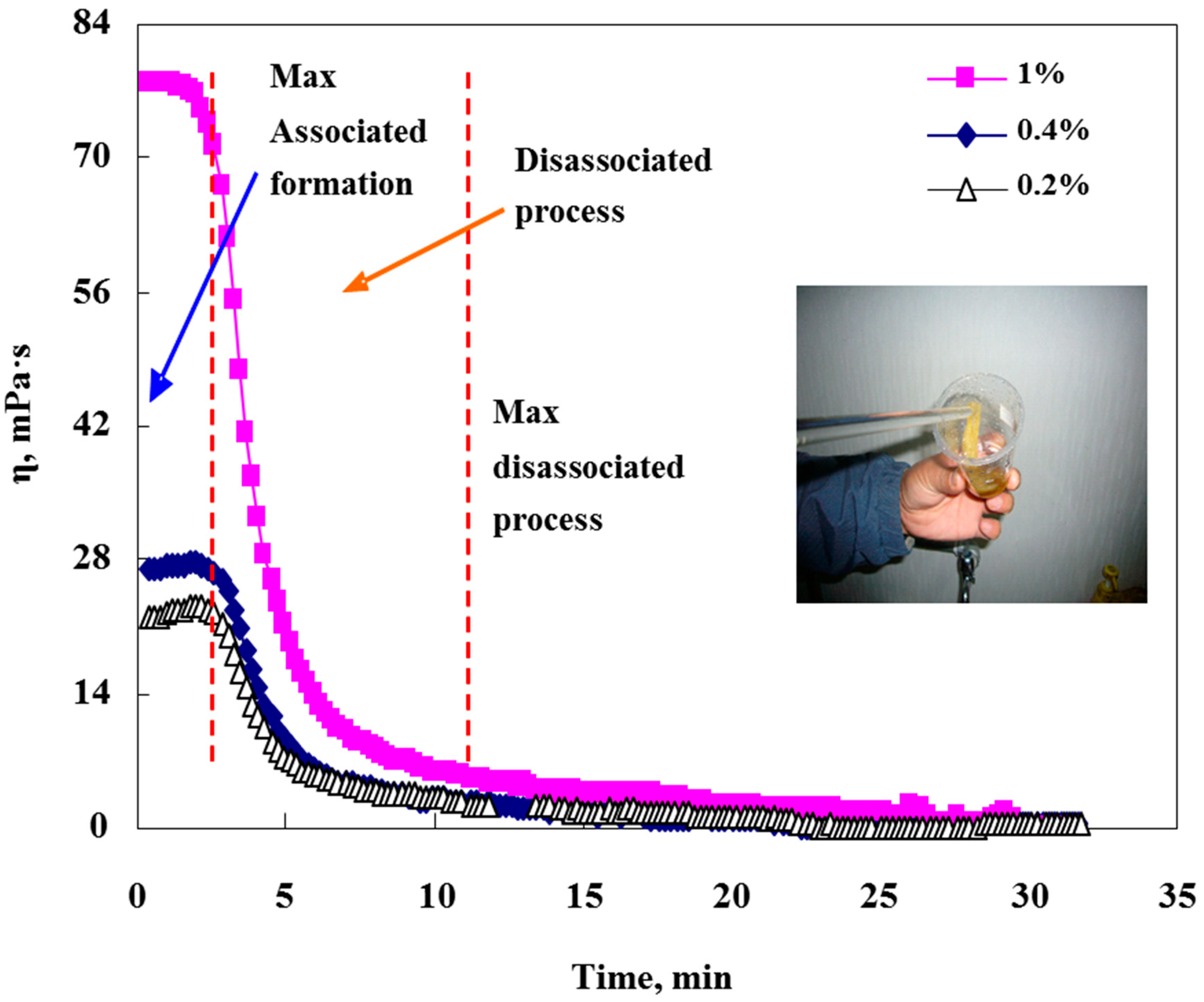
2.2.2. Rheological Investigation

A rheometer (Rheostess-600&ThermoHaake, Vreden, Germany) was used to evaluate the viscosity of spent acid solutions with a different concentration of VES and Ca2+. The solution was examined under a constant shearing rate of 170 s−1 and a temperature of 100 °C.

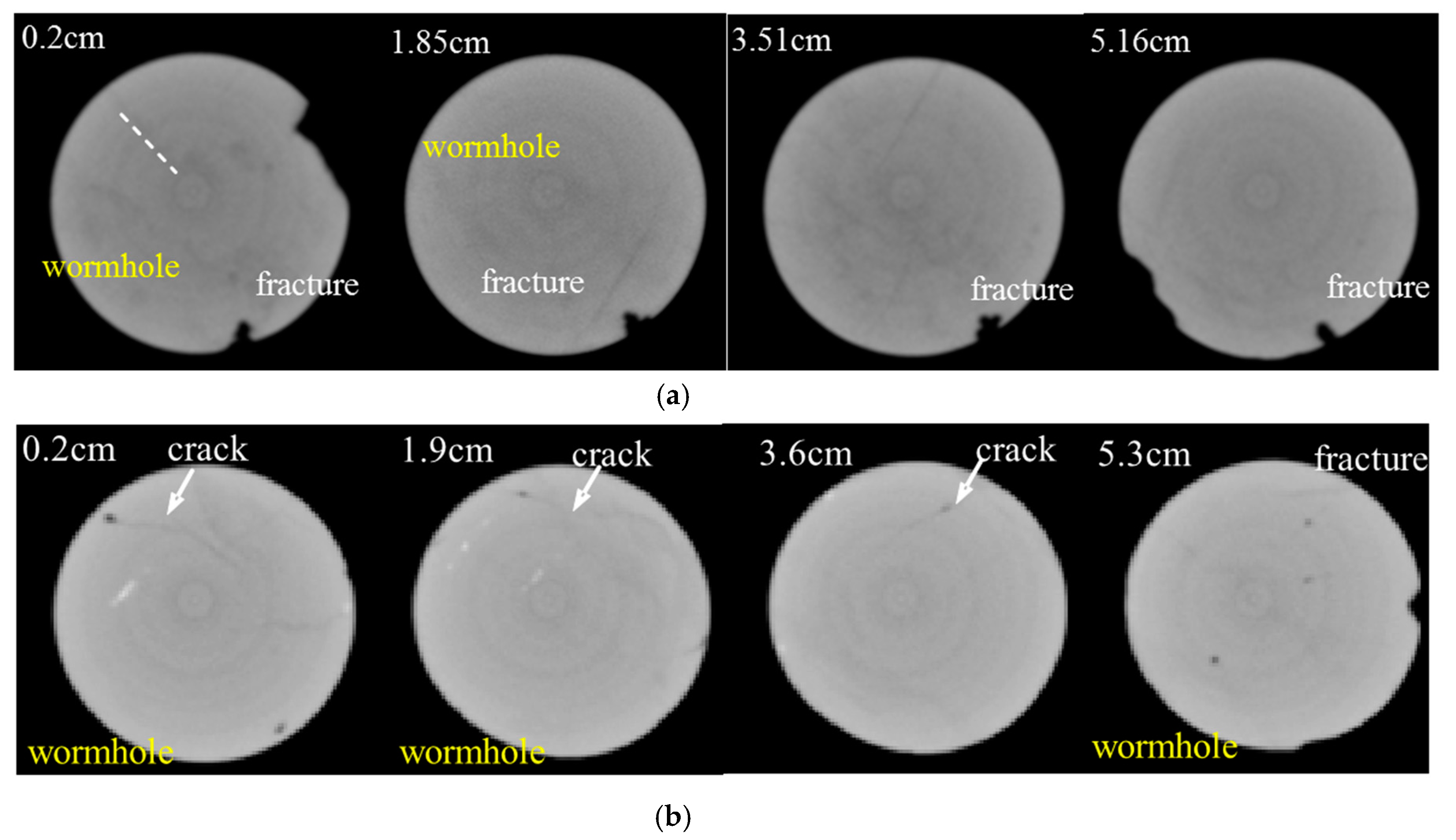
2.2.3. Core CT Analysis

After the core is cleaned and labeled, an industrial X-CT scan was primarily applied to characterize the original inner structure before the acid etching treatment. After the etching process, the core was scanned again to obtain its inner structure. The structural change caused by the acid etching process could then be studied by comparing the two scanning results.

2.2.4. Core Flooding Experiments

Acid fluid systems with different VES concentrations were injected into the cores at 70 °C. Pressures and flow rates were automatically recorded during the experiment. The experiment was terminated after the fluid completely broke through the outlet. The acid etching effect was evaluated through the change of inner structure and dynamic variation of injection pressure. Two core holders that connected in a parallel manner with a certain back pressure were set up to simulate the reservoir condition. The acid fracturing effect was characterized by the change of permeability and the inner structure of cores.

3. Results and Discussion

3.1. Effect of VES and Ca2+ Concentration on Fluid Viscosity

Figure 2 shows that a non-Newton flow with shear thinning characteristics appears when the VES concentration varies in range from 1% to 4%, and it becomes stronger with a further increase of VES concentrations (see Table 2). Moreover, it can be observed that the fluid viscosity decreases with time under the constant shear rate. Because the weak interaction of the micelle structure can be easily broken under strong shear stress, the effect of shear rate on viscosity follows the same trend [11]. The statistical regression results show that the viscosity decreases exponentially with time.
Figure 3 shows that the fluid viscosity varies directly with the CaCl2 concentration. Under a constant concentration of 4% VES, the fluid viscosity increased from 17 mPa·s to 60 mPa·s as the CaCl2 concentration increased from 0.2 wt.% to 1 wt.%. The increase of the fluid viscosity was subject to the variation of VES molecule aggregation manner [12]. The rod-shaped micelles that favored a higher pH value and concentration of divalent cations significantly increased the viscosity of spent acid. Micelles’ association through entanglement at higher VES concentration resulted in a 3D structure, which further increased the apparent viscosity of the fluid. The associated structure that increased the hydrodynamic volume of VES micelles was formed and increased with increasing saline solution. Hence, a higher apparent viscosity of solution was observed.
Comparing Figure 2 and Figure 3, we find that associated structure can easily be changed with fluid viscosity reduction at a high shear rate. Although the fluid with 1% CaCl2 had the highest viscosity compared to others in the experiments, the associated structure was broken, and the decreasing amount of this structure made the fluid viscosity sharply reduce and nearly equal to two other cases after more than 20 min shearing process.

3.2. Effect of VES Concentration on the Dissolution Quality

When VES was added to HCl, the generated Ca2+ during the reaction contributed to the association of VES which resulted in increasing the viscosity of the solution and reducing the mass transfer rate of H+. For the multiphase reaction of HCl and CaCO3, the reaction rate was mainly controlled by diffusion of H+, and it is reasonable to assume the dissolution occurs by a first-order heterogeneous chemical reaction [13].
The result in Figure 4 indicates that the mass reduction increases linearly with time during the period of 0 to 45 min when the VES concentration changes in the range from 1% to 4%. In this case, the weight loss of rock was around 3.0 g after 45 min reaction time. Therefore, we got an average value of 8.92 g·min−1·m−2 for the etching rate for the acid solution of 18% with a VES concentration varying from 1% to 2%. When the concentration of VES continually increased to 6%, the dissolution reaction rate changed in different reaction time ranges, but the reaction rate in the entire stage was relatively small. In summary, as the concentration of VES increased, the viscosity of the system increased, but the dissolution rate of the acid decreased.

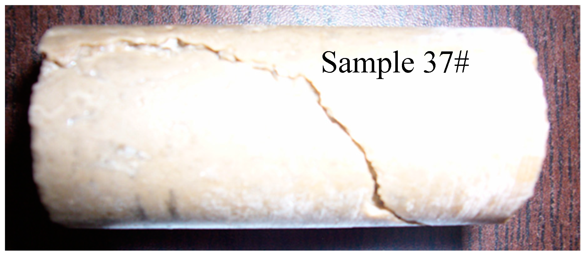
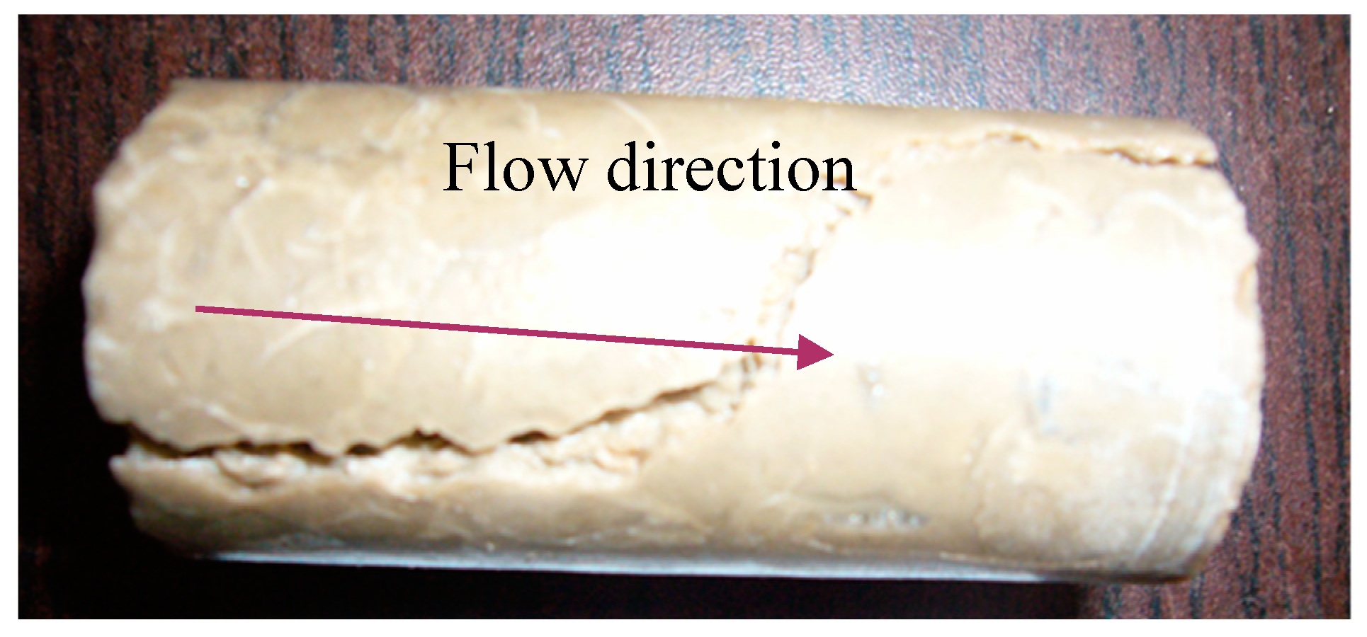
3.3. Single Core Flooding Experiments

To study the behavior of uninvaded rocks during the acidizing treatment, it is necessary to discuss the effect of reacting rate and the corresponding differential pressure on the inner structure change of core samples. Figure 5 shows the results of injection pressure drop and confining pressure and flow rate versus time for Sample 37. Injection pressure began to rise with time when the reaction started. By controlling a manual-screw pump, the confining pressure was reduced to smaller than the injection pressure and then filter loss occurred. Many experimental results have reported that filter loss occurs at a lower injection pressure than the confining pressure, leading to filter loss in the porous carbonate cores. In this experiment, however, most of the downhole sample had an uninvaded matrix and developed very little fine fractures. Hence, the filter loss normally did not appear on the core with such ultra-low permeability of 10−5 μm2.
Fine fractures and wormholes were observed under industrial X-CT, larger fractures can be visually observed. Figure 6 shows the morphology of Sample 37 after an acid fracturing process. It can be seen that a fracture was created with a varied width of 1–3 mm and 1 mm depth on the surface. Figure 7 gives a deep insight into inner structure variation before, as shown in Figure 7a, and after, as shown in Figure 7b, the acid treatment process. The slides at different locations of the core indicate that fractures were formed with different widths and depths.
The permeability of Sample 37 for water after acid etching is 6.78 μm2, which is more than 4 orders of magnitude larger than its initial value. Based on Figure 4, when considering the influence of foam, a lower etching rate of 5.92 g·min−1·m−2 during the etching process and around 1.0 g of carbonate rock are reacted. Given the rock density was 2.7 g/cm3, the calculated diameter of the channel diameter is 3.0 mm, which is consistent with the flow experiment results.
As shown in Figure 8, injection pressure with larger variation and even higher than the confining pressure is observed during the period of 2–30 min. Fracturing treatment took effect in this interval. The injection pressure continually decreased and vibrated to an even larger degree and always stayed lower than the confining pressure during the period of 30–60 min. Fractures initiated and propagated with decreasing flow resistance and increasing permeability of cores.
A fracture with different depths displayed on the core surface that is almost parallel to the flow direction, with only deviation at the middle and end of the core can be seen in Figure 9. Before the acid etching, as shown in Figure 10a, the fracture in the second and third slice of the core nearly crosses the core’s cross-section.
The original permeability of this core is 0.02 × 10⁻³ μm2. After the acid treatment, a major fracture can be seen with a zigzag shape and rough surface. The permeability of cores after acid fracturing is 35.93 μm2, which shows a successful treatment.
Another conclusion can also be drawn from the experiments that the filter loss was an effective way to enhance etching reaction areas of cores as well as reaction rates by reducing the confining pressure. The generated foam and the increased viscosity of VES fluid greatly increased the injection pressure, which was higher than the confining pressure, and reduced the amount of filter loss. The effect of etching/fracturing existed whenever the injection pressure was greater than confining pressure.

3.4. Parallel Core Flooding Experiment

Figure 11 presents the results of the flow experiment for Samples 14 and 17 which connected in a parallel manner. For Sample 14, the difference between the confining pressure and injection pressure gradually decreased, and eventually reached zero after 50 min. For Sample 17, the confining pressure maintained a constant value even when the injection pressure sharply decreased. As shown in Figure 12, the morphology of the two samples was quite different after being taken out. For Sample 14, a wider and deeper fracture was formed compared to that of Sample 17 parallel to the axle after the acid etching process. There is a short and shallow etching fracture located on the surface of sample 17 and intersected with the axle at an angle of about 70°.
The X-CT scanning results in Figure 13 show that besides a major fracture forming on the surface of Sample 14, there are several wormholes and small fractures as well. Due to the flow capacity and sensitivity to the confining pressure, the fracture on the core surface will significantly reduce the core’s permeability by a higher confine pressure. The two pressure curves had the same variation trend, and even had the same value when the fracture was completely closed. As for Sample 17, where mainly wormholes developed, small fractures produced on the surface of the core had little contribution to the permeability enhancement and less influence of confining pressure on the variation of injection pressure. Based on the relationships between the injection pressure and the confining pressure, the effect of acid fracturing mainly happened on Sample 14, and the etching mainly took effect on Sample 17. Hence, the variation of pressures indicates the change of the core’s inner structure.

3.5. Mechanism of VES on Carbonate Rocks with Uninvaded Matrix

Fractures and wormholes are created during acid treatment and serve as a highly conductive path to increase production rate. According to the results of the core flow experiment, a successful acid treatment will significantly increase the core’s permeability (even by multiple orders of magnitude) with fractures or wormholes produced. The reaction speed of HCl and carbonate reservoirs is extremely fast so that the acid may be mainly consumed in the near well area. Due to the low viscosity of the system, the filtration is very fast, and it is difficult to exert the effect of “fracturing” and form effective cracks. Therefore, for carbonate rocks with the uninvaded matrix, an appropriate increase in the rate of filtration loss will help improve the effect of acid fracturing. While for cores with high permeability, the extremely high fluid loss will lead to acid fracturing failure.
As the acid reacts with carbonate rock, larger amounts of CO2 is produced and dissolved in the solution, and its concentration increases with time under higher pressure. Gas nuclei generate when several CO2 molecules gather and grow into a state of “gas phase” that separates CO2 from the solution. Foam is created in-situ by the uniform separation of gas in the VES solution. At the early stages, a lower filter loss and a greater amount of CO2 result in the injection pressure increase even higher than the confining pressure. The foam viscosity is also increased with the increase of the gas volume and Ca2+ [14]. A higher flow resistance is produced that can hold a higher pressure drop during the filtering time period. Due to the presence of the two phases, the flow is highly transient and that inevitably leads to a flow with a vibration of injection pressure. Therefore, the higher flow resistance of foam and the faster increase of CO2 volume results in an injection pressure with a vibration higher than the confining pressure. This pressure drop plays a major role in the fracture creation process of the core.
It can be concluded that the CO2 gas phase appears and the foam is created due to the increasing amount of CO2 production at higher HCl concentrations. Bernadiner reported that foam can produce a uniform dissolution channel primarily because foam inhibits acid leak-off from the sides of the wormhole [15]. Consequently, nearly all the acid is spent forming a single primary channel. Furthermore, if the acid is carried with the CO2 foam, it will travel further and etch deep inside of the core, which is conducive to wormhole formation with a longer length.

4. Conclusions and Future Work

We successfully conducted acid etching experiments on uninvaded matrix carbonate cores by using VES acid fluid and evaluated the influence of reaction characteristics of acid fluid and carbonate on the flow behavior. The following conclusions can be drawn:
(1)
As the concentration of VES and CaCl2 increases, the viscosity of the system increases. The generated Ca2+ during the reaction contributes to the association of VES which results in increasing the viscosity of the solution and reducing the mass transfer rate of H+.
(2)
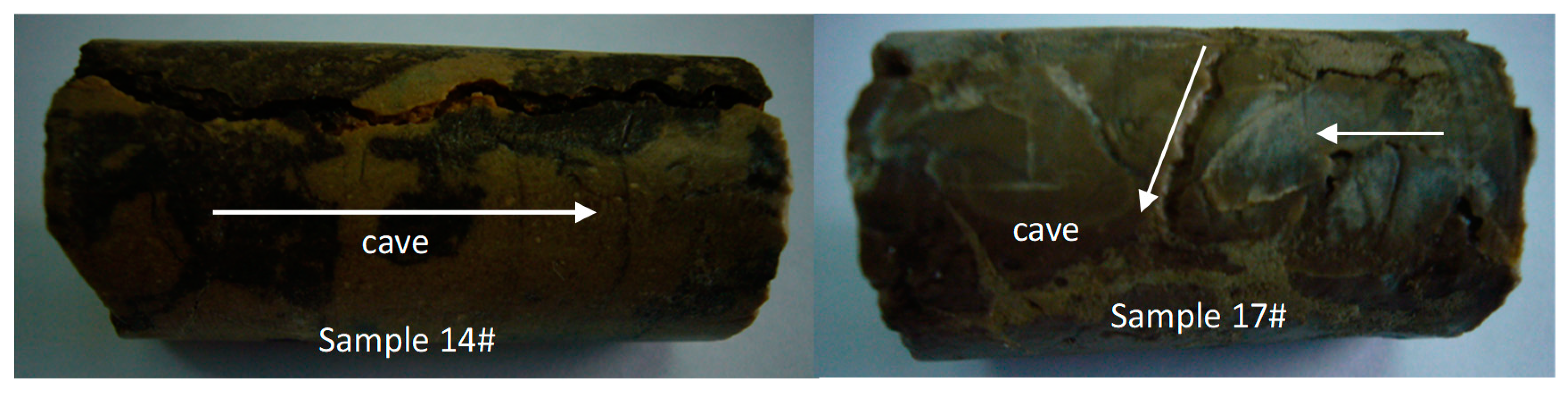
Foam in-situ produced during the etching process is the major contribution to the fluid viscosity enhancement. The permeability of the fracture, formed on the surface of the core, is more sensitive to the confining pressure.
(3)
For carbonate rocks with the uninvaded matrix, an appropriate increase in the rate of filtration loss will help improve the effect of acid fracturing. While for cores with high permeability, the extremely high fluid loss will lead to acid fracturing failure.
(4)
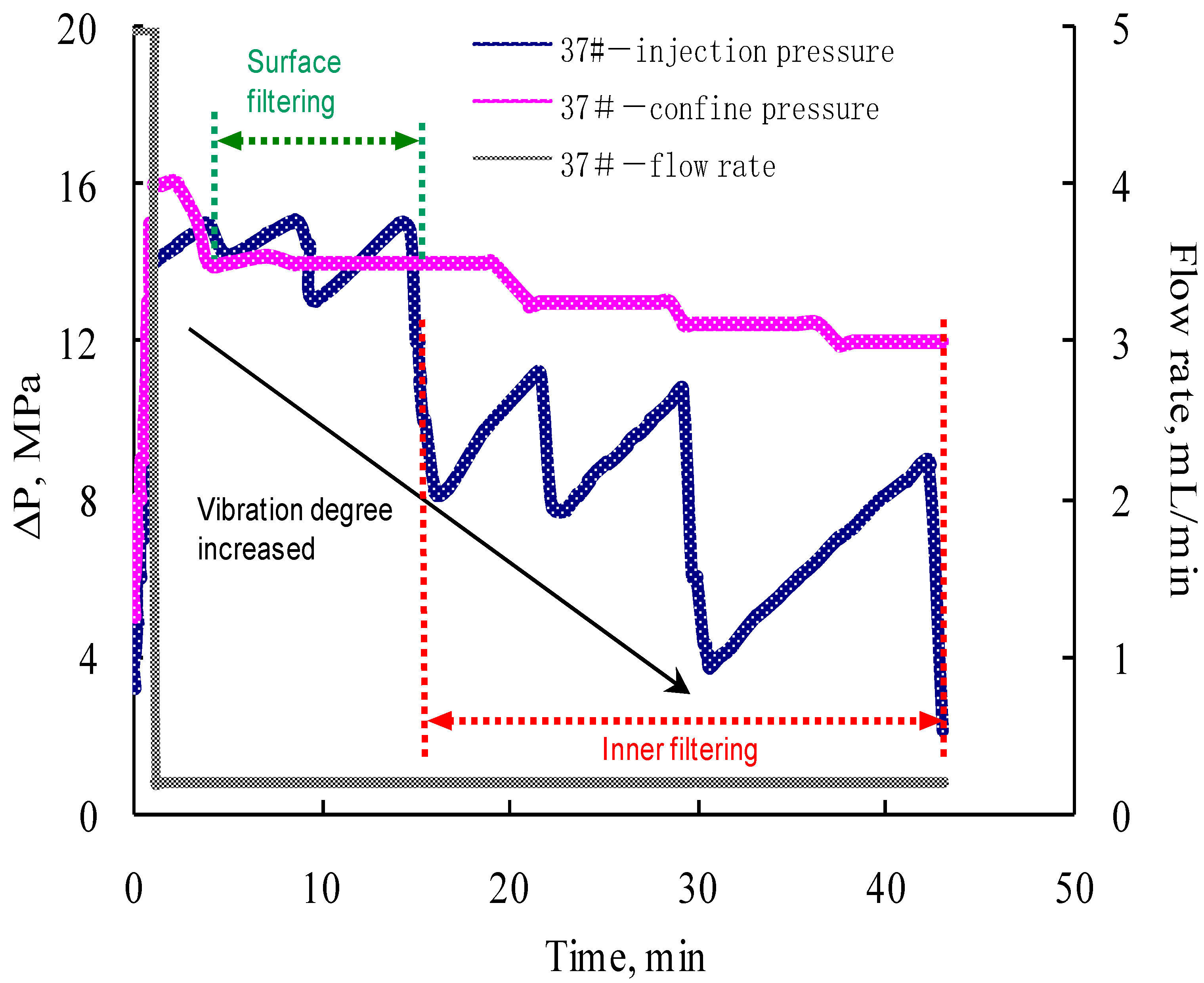
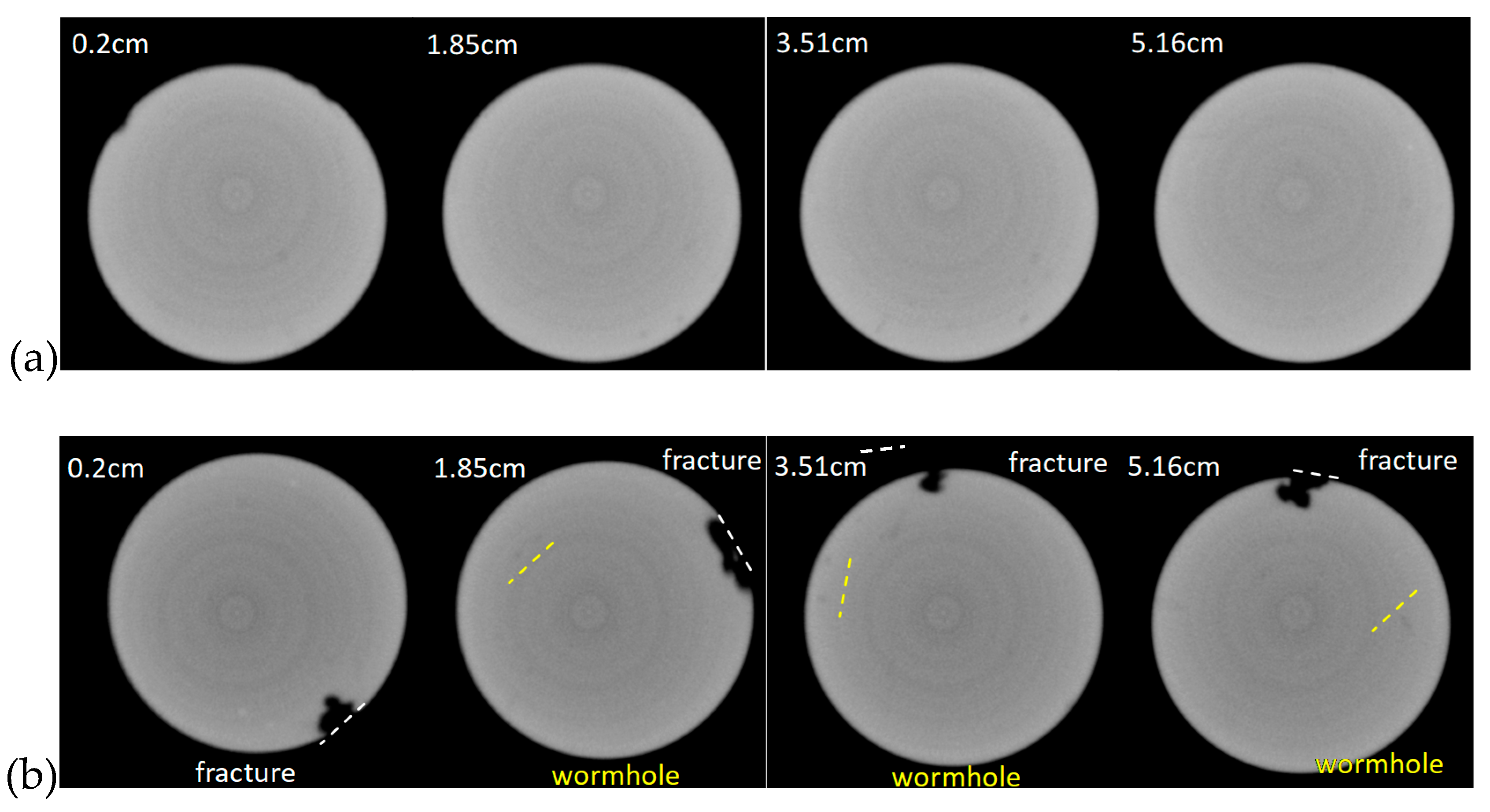
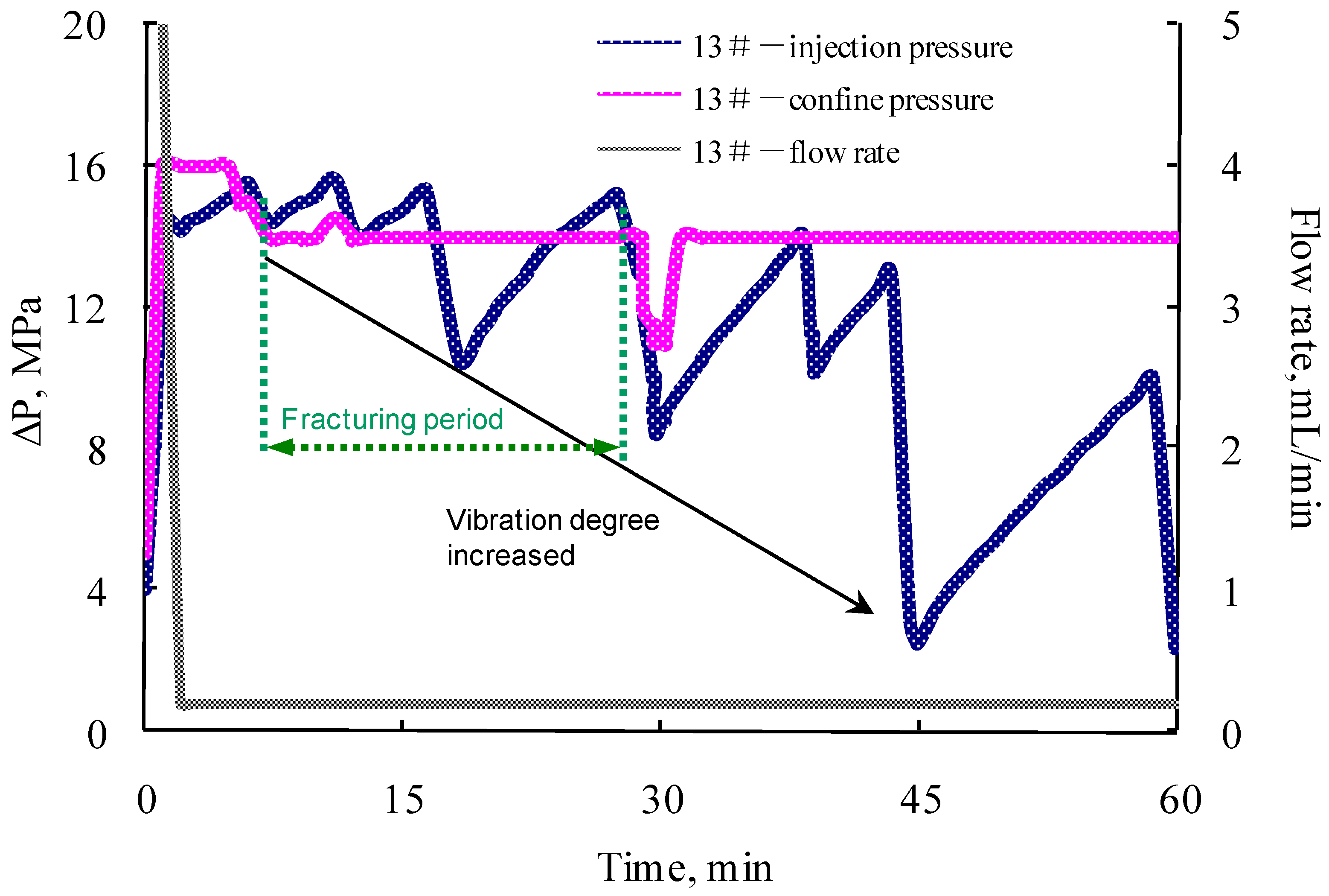
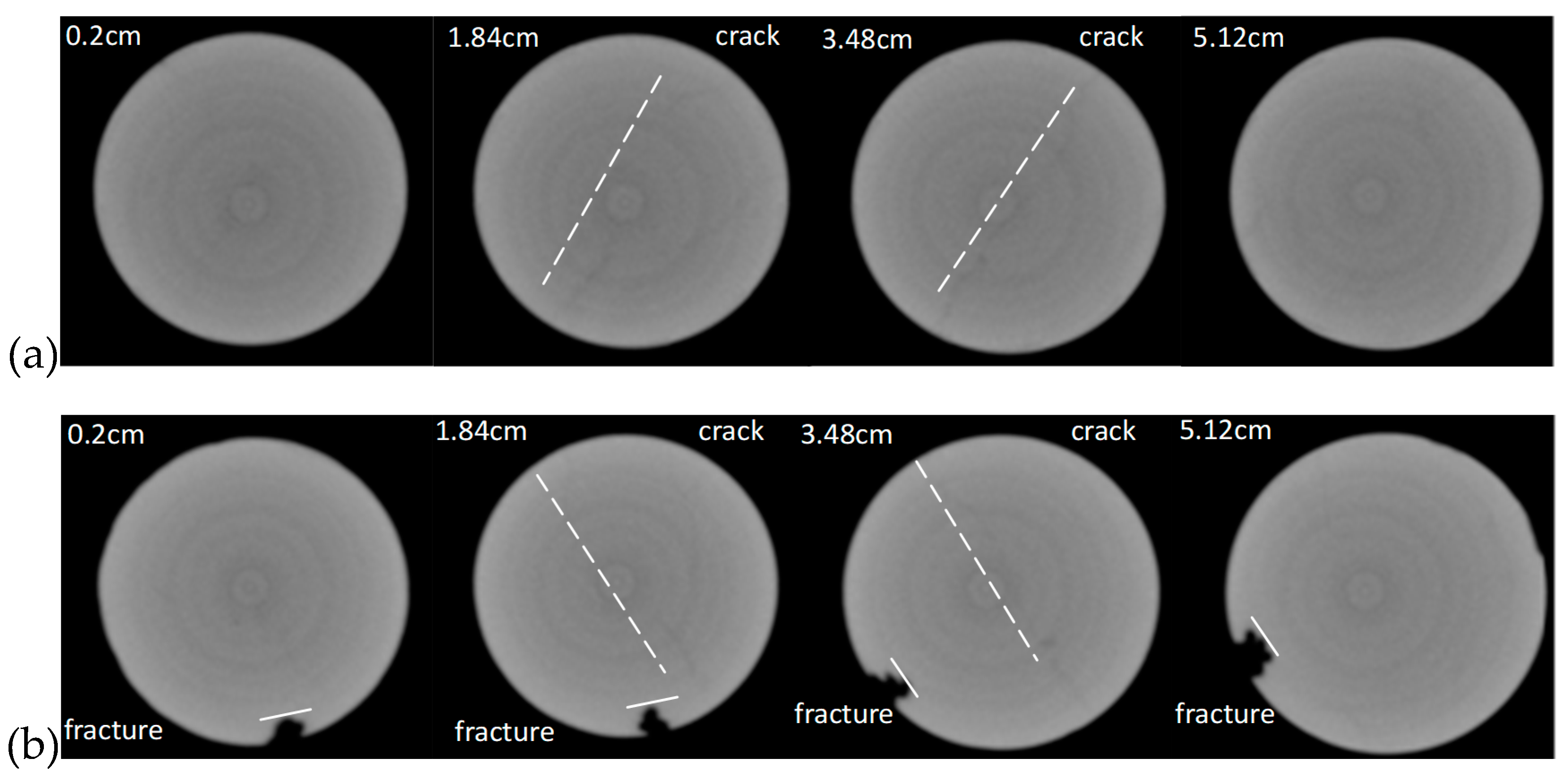
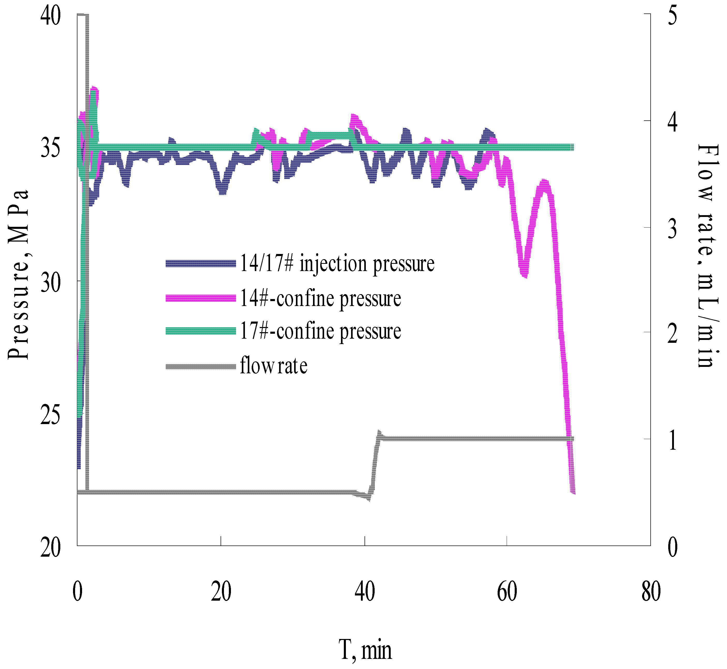
The formation and propagation of the VES-foam system change the injection pressure and varies periodically when the confining pressure is set lower than the injection pressure. Fractures are created on the surface and formed after the acid breakthrough.
(5)
Wormholes are preferably produced around the pre-developed micro-cracks, which depends on the original characteristics of the fracture distribution of the reservoir, and have a major control on the treatment effect, causing the uncertainty of the treatment effect to be noticeably increased.

Author Contributions

Y.W. supervised the whole process and provided laboratory for this research. W.L. and H.W. conceived and designed the experiments. W.L. and H.F. performed the experiments. X.J. analyzed the data. X.J. and S.Y. wrote the paper.

Acknowledgments

This research was funded by Northwest Branch Company, SINOPEC (grant number: 34400007-12-ZC0607-0062). We also thank Ye Zhang and Tao Lin at Northwest Branch Company, SINOPEC, for the valuable discussions on this paper.

Conflicts of Interest

The authors declare no conflict of interest.

References

  1. Hull, K.L.; Sayed, M.; Al-Muntasheri, G.A. Recent Advances in Viscoelastic Surfactants for Improved Production from Hydrocarbon Reservoirs. SPE J. 2016, 21, 1–340. [Google Scholar] [CrossRef]
  2. Chang, F.F.; Love, T.; Affeld, C.J.; Blevins, J.B., III; Thomas, R.L.; Fu, D.K. January. Case study of a novel acid-diversion technique in carbonate reservoirs. In SPE Annual Technical Conference and Exhibition; Society of Petroleum Engineers: Houston, TX, USA, 1999. [Google Scholar]
  3. Lungwitz, B.R.; Fredd, C.N.; Brady, M.E.; Miller, M.J.; Ali, S.A.; Hughes, K.N. Diversion and Cleanup Studies of Viscoelastic Surfactant-Based Self-Diverting Acid; Society of Petroleum Engineers: Houston, TX, USA, 2007. [Google Scholar] [CrossRef]
  4. Jardim Neto, A.T.; Silva, C.A.M.; Torres, R.S.; Farias, R.L.; Prata, F.G.M.; Souza, L.A.M.; Sandes, E.F. Self-diverting acid for effective carbonate stimulation offshore Brazil: A successful history. In SPE European Formation Damage Conference & Exhibition; Society of Petroleum Engineers: Houston, TX, USA, 2013. [Google Scholar]
  5. Alleman, D.; Qi, Q.; Keck, R. The development and successful field use of viscoelastic surfactant-based diverting agents for acid stimulation. In International Symposium on Oilfield Chemistry; Society of Petroleum Engineers: Houston, TX, USA, 2003. [Google Scholar]
  6. Gomaa, A.M.; Wang, G.; Nasr-El-Din, H.A. An Experimental Study of a New VES Acid System: Considering the Impact of CO2 Solubility; Society of Petroleum Engineers: Houston, TX, USA, 2011. [Google Scholar] [CrossRef]
  7. Wang, G.; Gomaa, A.M.; Nasr-El-Din, H.A. Effect of Initial HCl Concentration on the Performance of New VES Acid System; Society of Petroleum Engineers: Houston, TX, USA, 2011. [Google Scholar] [CrossRef]
  8. Mou, J.; Liu, M.; Zheng, K.; Zhang, S. Diversion Conditions for Viscoelastic-Surfactant-Based Self-Diversion Acid in Carbonate Acidizing; Society of Petroleum Engineers: Houston, TX, USA, 2015. [Google Scholar] [CrossRef]
  9. Tan, X.; Weng, X.; Cohen, C.-E. An Improved Wormhole Propagation Model with a Field Example; Society of Petroleum Engineers: Houston, TX, USA, 2016. [Google Scholar] [CrossRef]
  10. Hosseinzadeh, B.; Bazargan, M.; Rostami, B.; Ayatollahi, S. Modeling of Wormhole Propagation in Carbonate Rocks by Use of In-Situ-Gelled Acids; Society of Petroleum Engineers: Houston, TX, USA, 2017. [Google Scholar] [CrossRef]
  11. Ratnakar, R.R.; Kalia, N.; Balakotaiah, V. Modeling, analysis and simulation of wormhole formation in carbonate rocks with in situ cross-linked acids. Chem. Eng. Sci. 2013, 90, 179–199. [Google Scholar] [CrossRef]
  12. Nasr-El-Din, H.A.; Al-Ghamdi, A.H.; Al-Qahtani, A.A.; Samuel, M.M. Impact of acid additives on the rheological properties of a viscoelastic surfactant and their influence on field application. SPE J. 2008, 13, 35–47. [Google Scholar] [CrossRef]
  13. Fredd, C.N.; Fogler, H.S. Influence of transport and reaction on wormhole formation in porous media. AIChE J. 1998, 44, 1933–1949. [Google Scholar] [CrossRef]
  14. Valko, P.; Economides, M.J. Volume equalized constitutive equations for foamed polymer solutions. J. Rheol. 1992, 36, 1033–1055. [Google Scholar] [CrossRef]
  15. Bernadiner, M.G.; Thompson, K.E.; Fogler, H.S. Effect of Foams Used During Carbonate Acidizing. SPE Prod. Eng. 1992, 7, 350. [Google Scholar] [CrossRef]
Figure 1. Acid fracturing system.
Processes 07 00159 g001
Figure 2. Effect of VES concentrations on fluid viscosity (1.44% HCl and 1% CaCl2).
Processes 07 00159 g002
Figure 3. Effect of CaCl2 concentration on fluid viscosity (1.44% HCl and 4% VES).
Processes 07 00159 g003
Figure 4. Effect of VES concentration on the dissolution quality.
Processes 07 00159 g004
Figure 5. Pressure and flow rate versus time during the acid fracturing process of sample 37 (1.5 VES, 27% HCl).
Processes 07 00159 g005
Figure 6. Morphology of sample 37 after acid fracturing.
Processes 07 00159 g006
Figure 7. Industrial CT scanning on sample 37 (a) before and (b) after acid fracturing.
Processes 07 00159 g007
Figure 8. Pressure and flow rate versus time during the acid fracturing process of sample 13 (1.5 VES, 27% HCl).
Processes 07 00159 g008
Figure 9. Morphology of sample 13 after acid fracturing.
Processes 07 00159 g009
Figure 10. Industrial CT scanning on sample 13: (a) before and (b) after acid fracturing.
Processes 07 00159 g010
Figure 11. Parameters change with time during the acid fracturing process on two samples (1.5 VES, 18.2% HCl).
Processes 07 00159 g011
Figure 12. Morphology of two samples after acid fluid processing.
Processes 07 00159 g012
Figure 13. Industrial CT scanning after acid fracturing: (a) sample 14 and (b) sample 17.
Processes 07 00159 g013
Table 1. Collection of core parameters experimental data.
Core-Flow ExperimentsCore SampleLength
(cm)
Permeability
(×10−3 μm2)
VES Concentration
(%)
HCl Concentration
(%)
Single375.3340.0021.527
135.3250.0201.527
Parallel145.3650.0251.518.2
175.4980.0631.518.2
Table 2. Fitting results of rheological behavior at different VES concentration.
VES Concentration, %wtFitting Results (Constant Shear Rate, 100 s−1)
1y = 0.891e−0.0376x, R2 = 0.6201
2y = 3.5434e−0.0763x, R2 = 0.8244
4y = 9.1183e−0.0987x, R2 = 0.9034

