The Effects of Backfill Mining on Strata Movement Rule and Water Inrush: A Case Study

Abstract
:1. Introduction
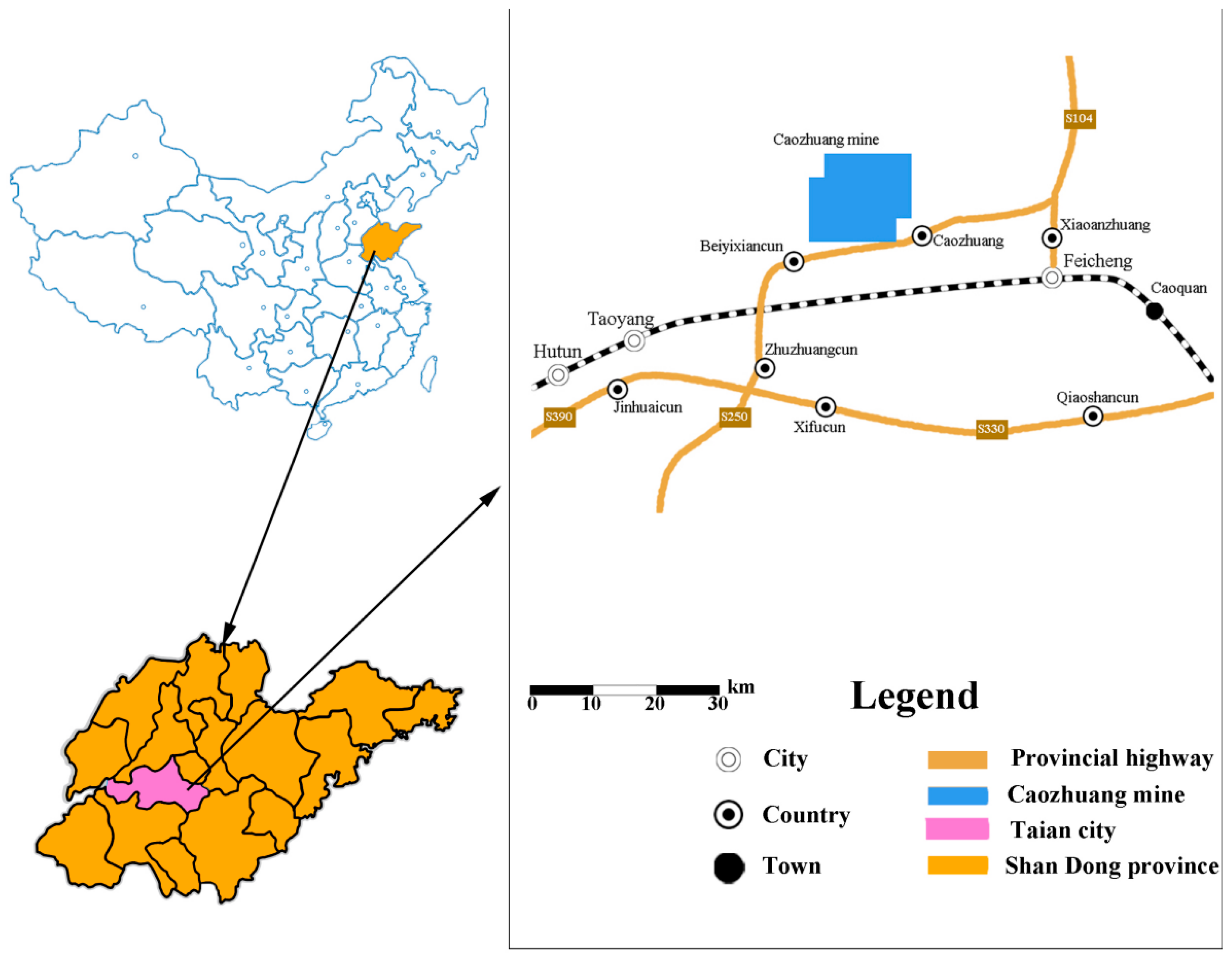
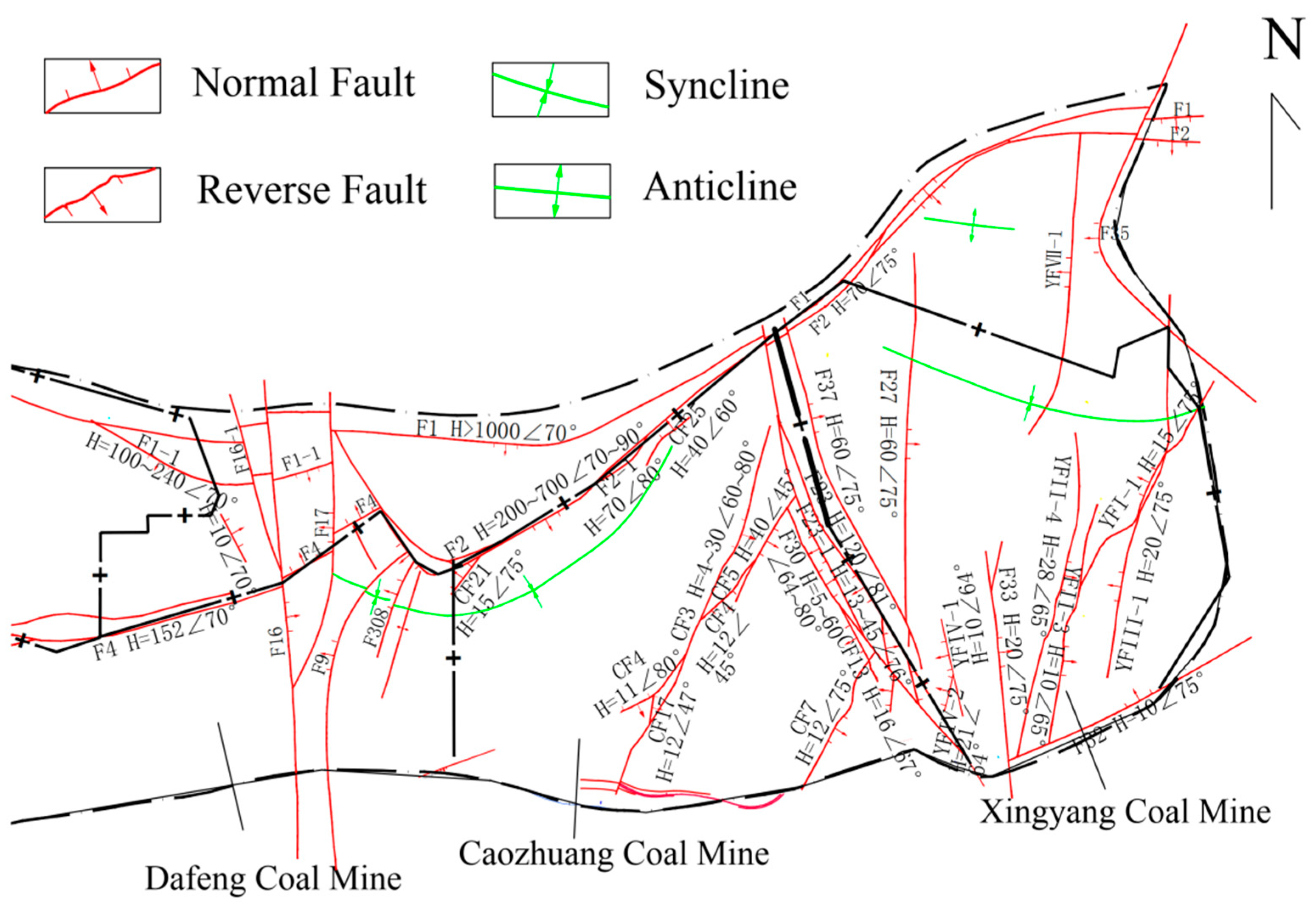
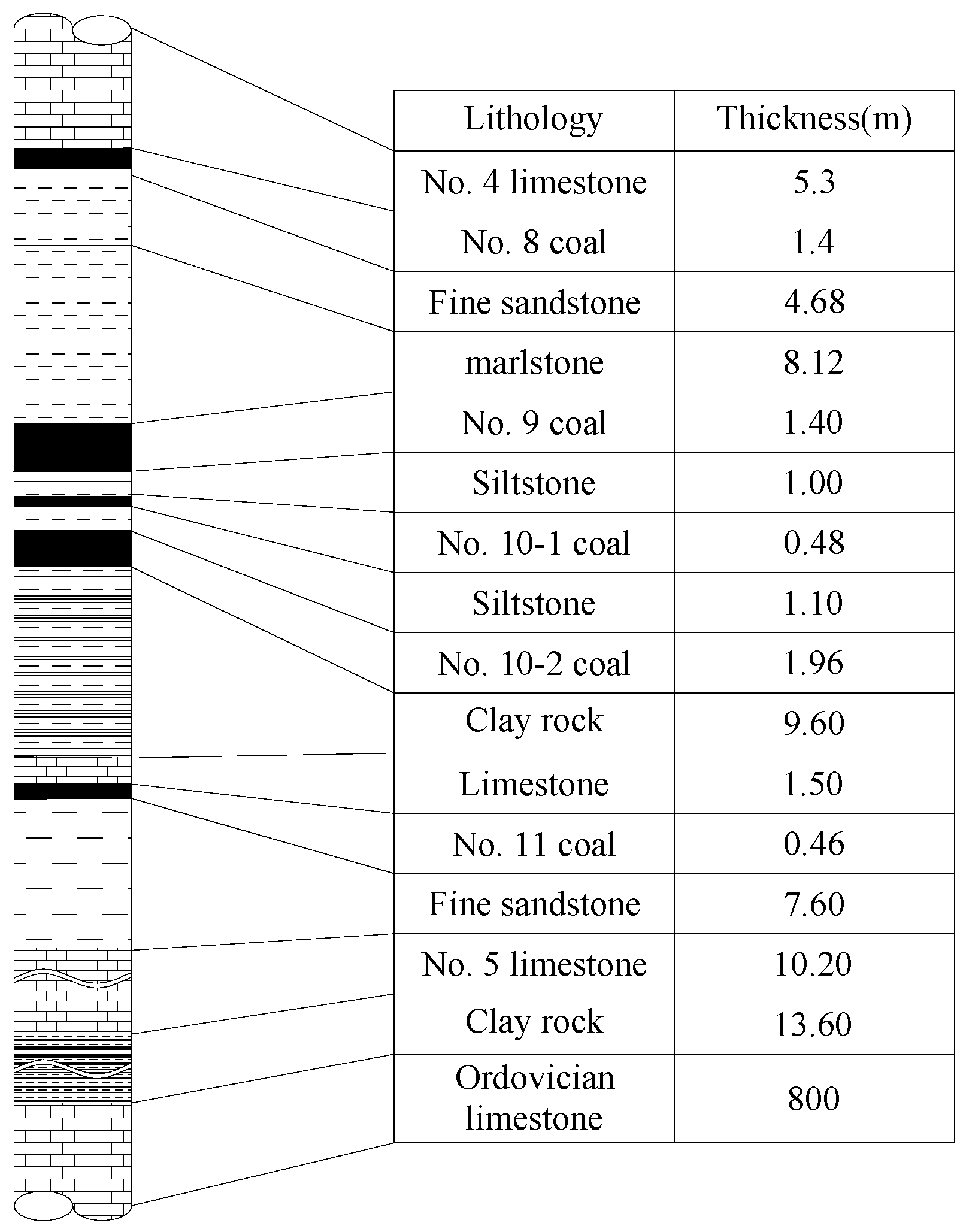
2. Study Area
3. The Backfill System and Process
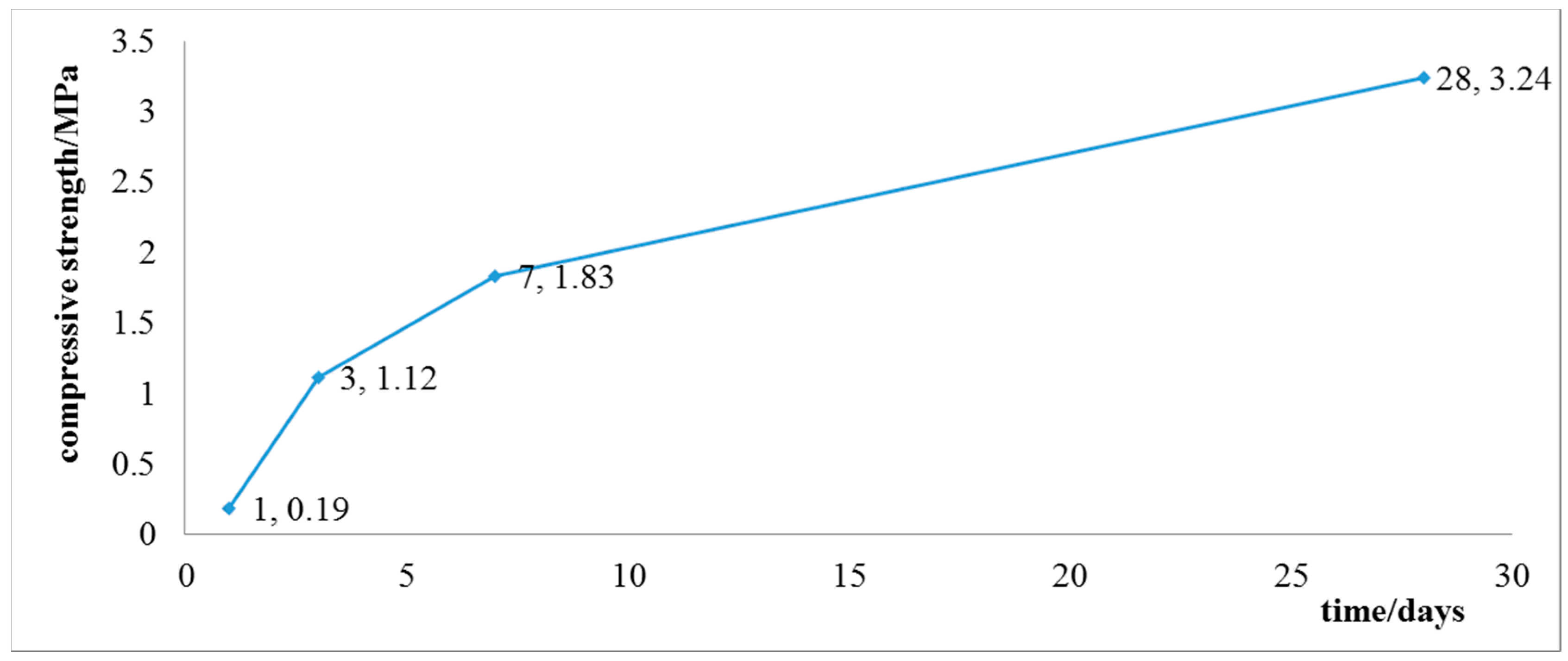
3.1. Materials and Methods
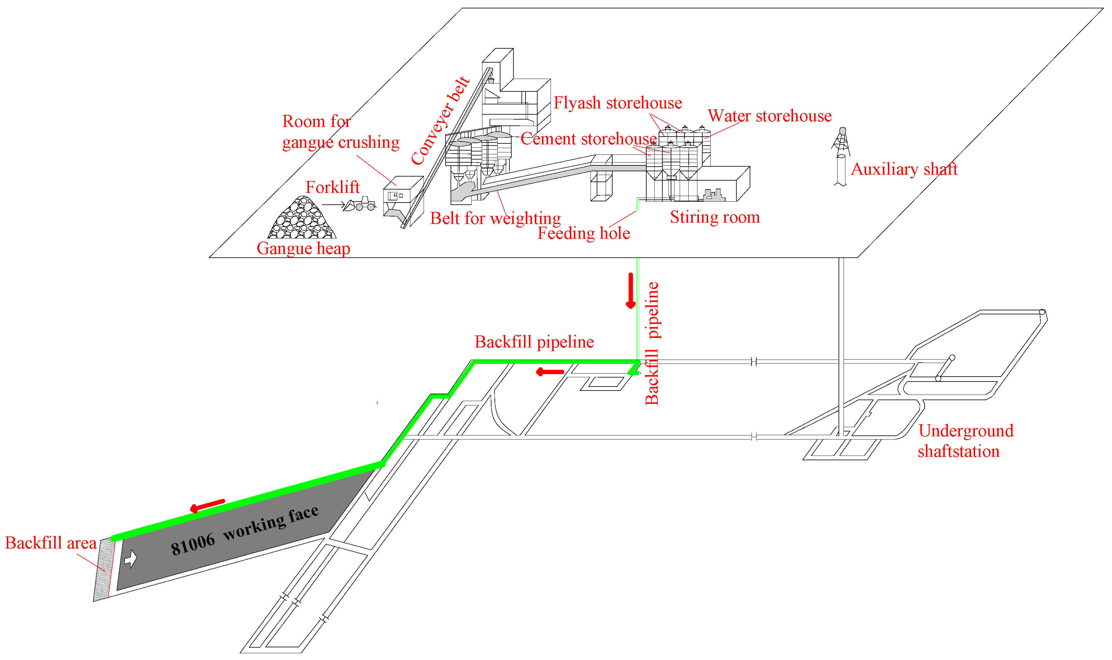
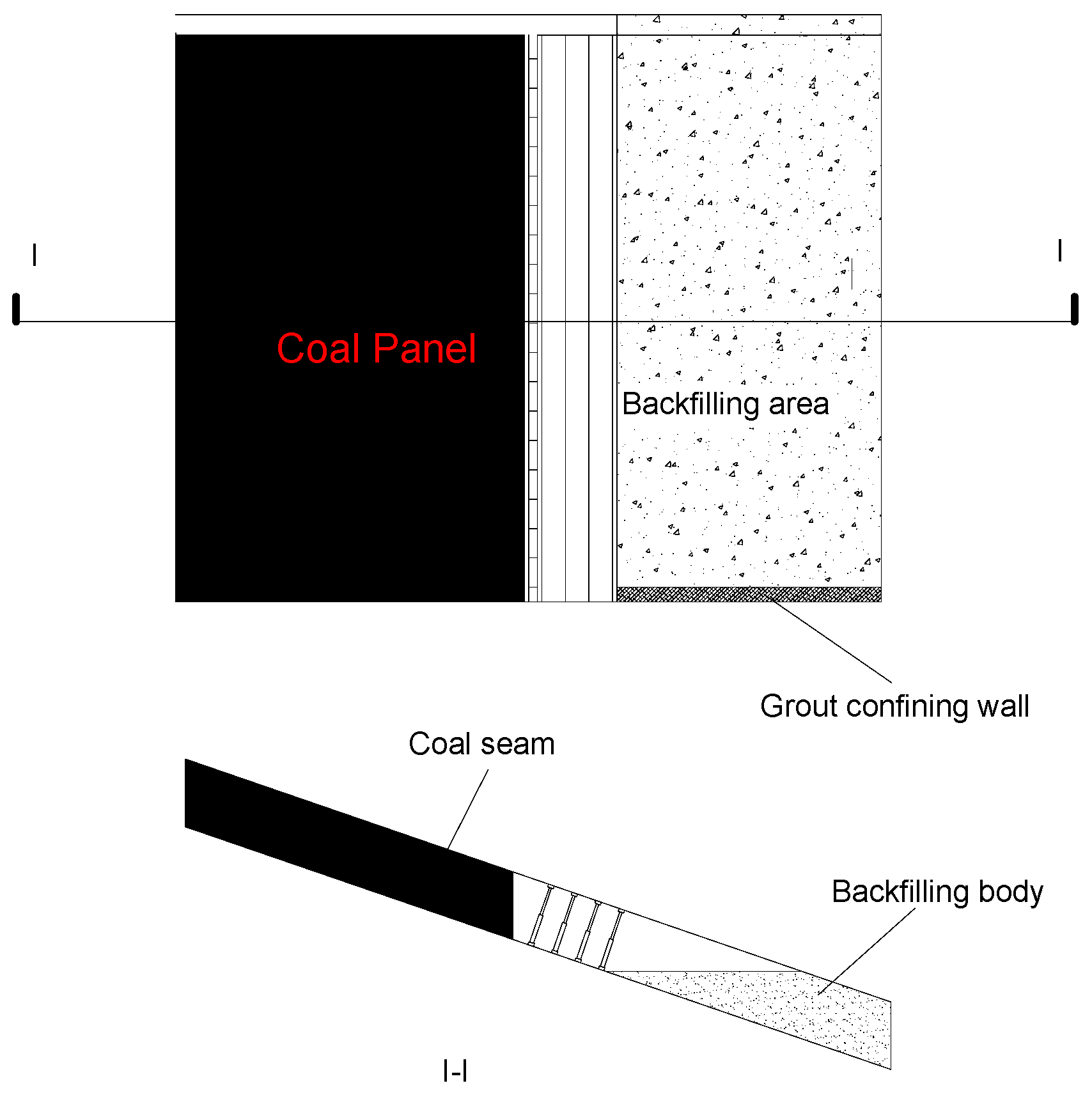
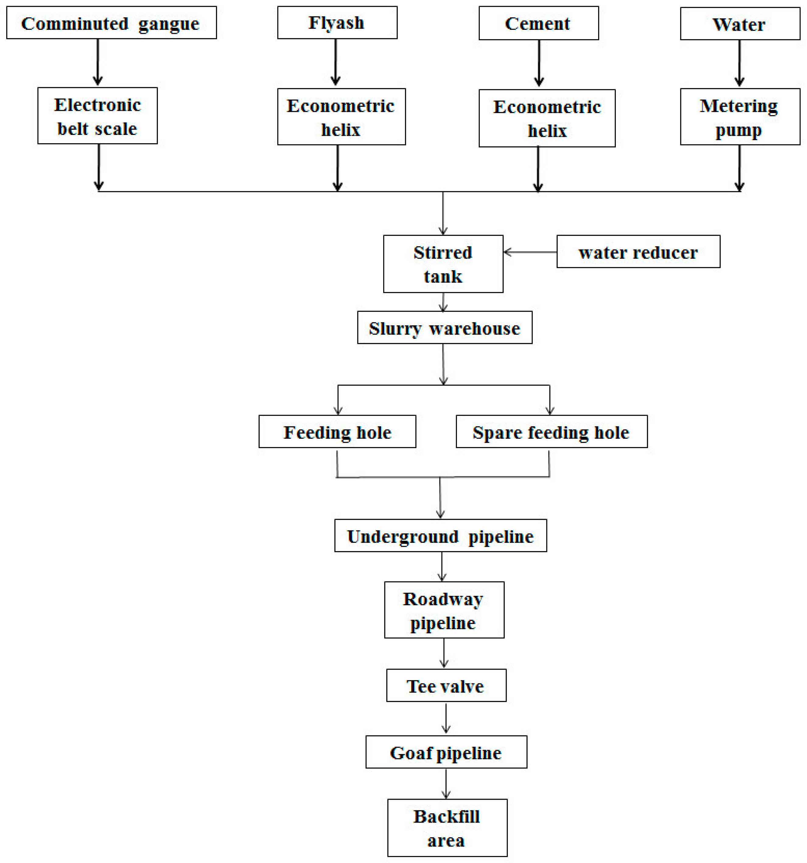
3.2. Backfill System
4. Field Monitoring Equipment and Layout
4.1. Surrounding Rock Responding Monitoring Equipment in Backfill Coal Panel
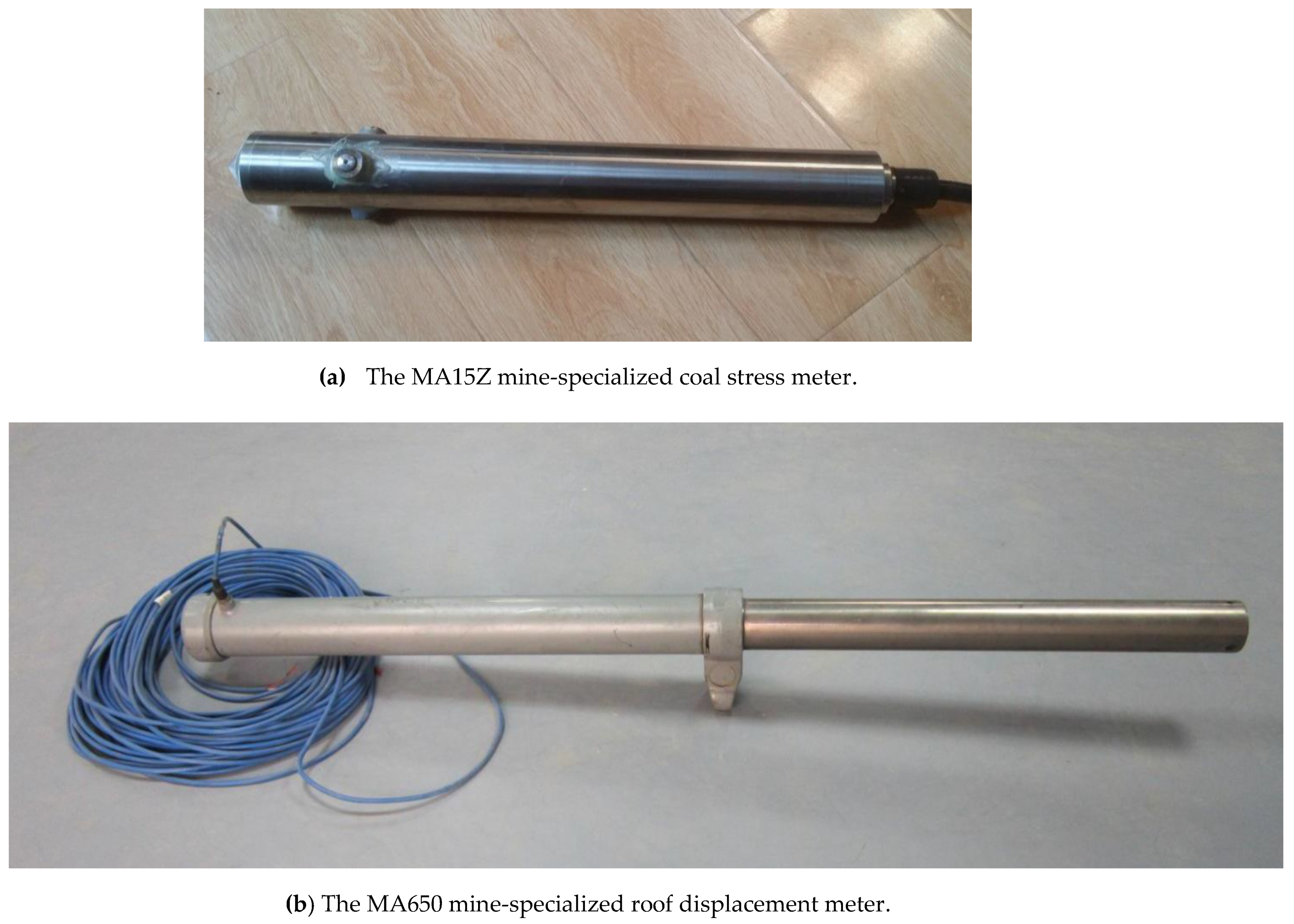
4.1.1. Introduction
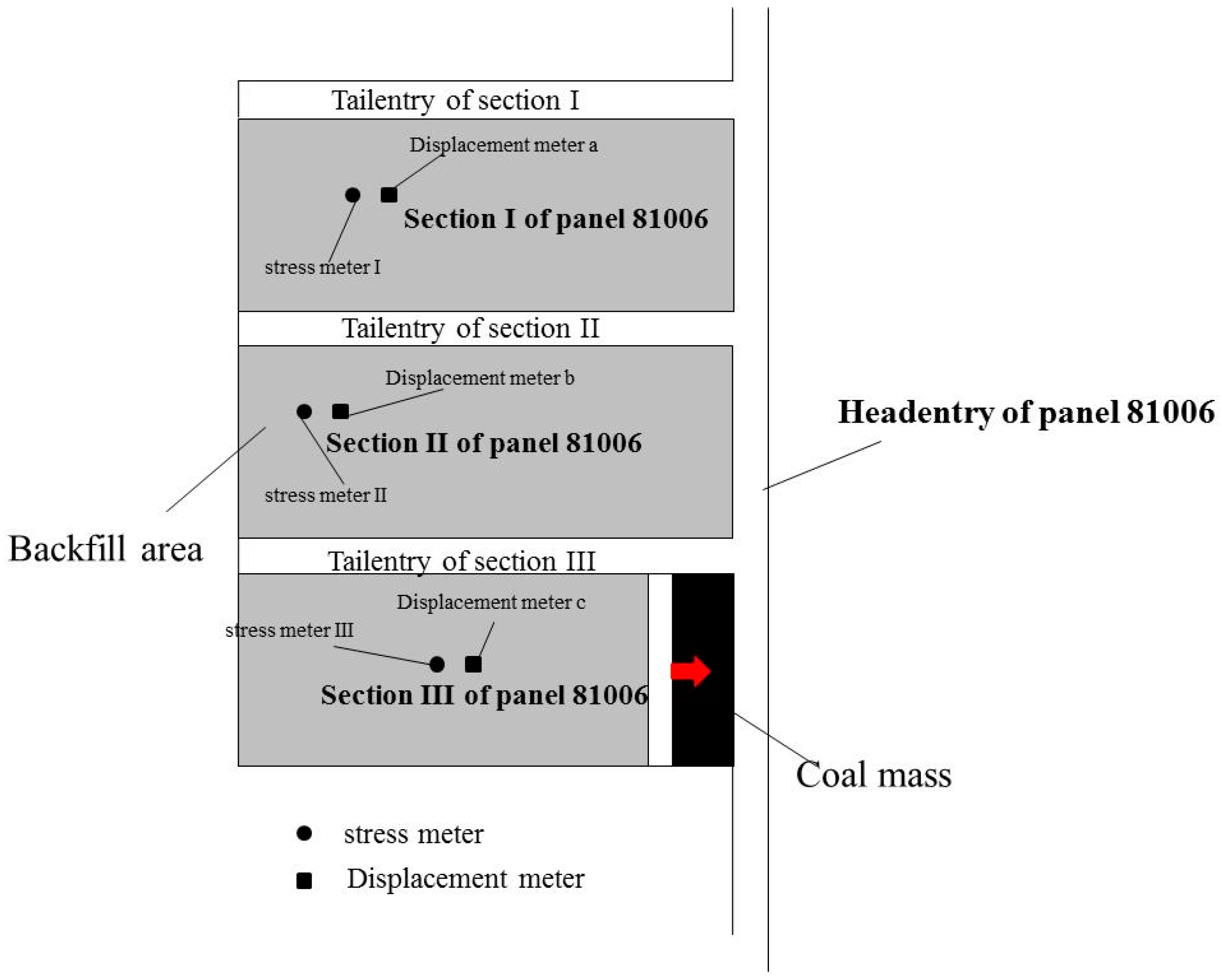
4.1.2. Monitoring Equipment Layout
4.2. Floor failure Depth (FFD) Detecting Equipment and Detecting Method
4.2.1. Introduction
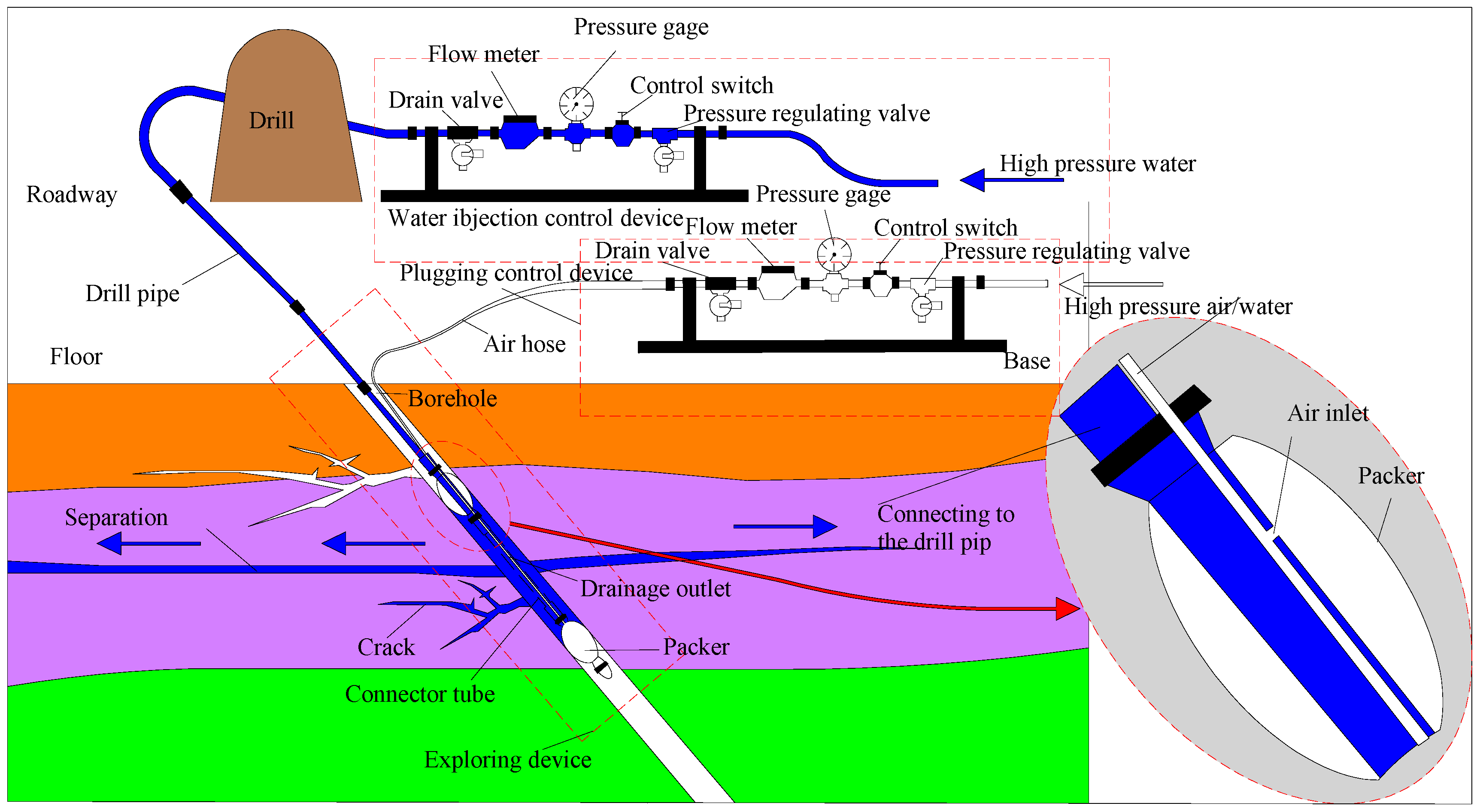
4.2.2. Detecting Method
5. Results and Discussion
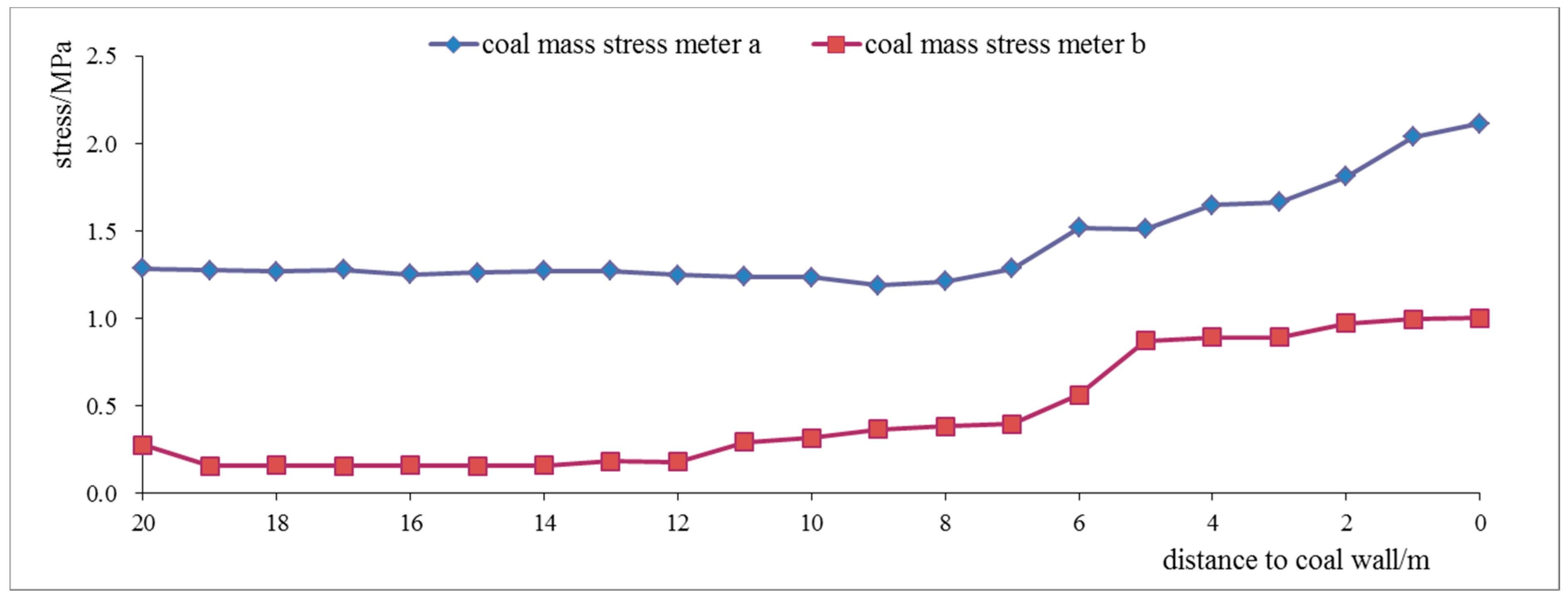
5.1. Abutment Pressure Distribution Characteristics
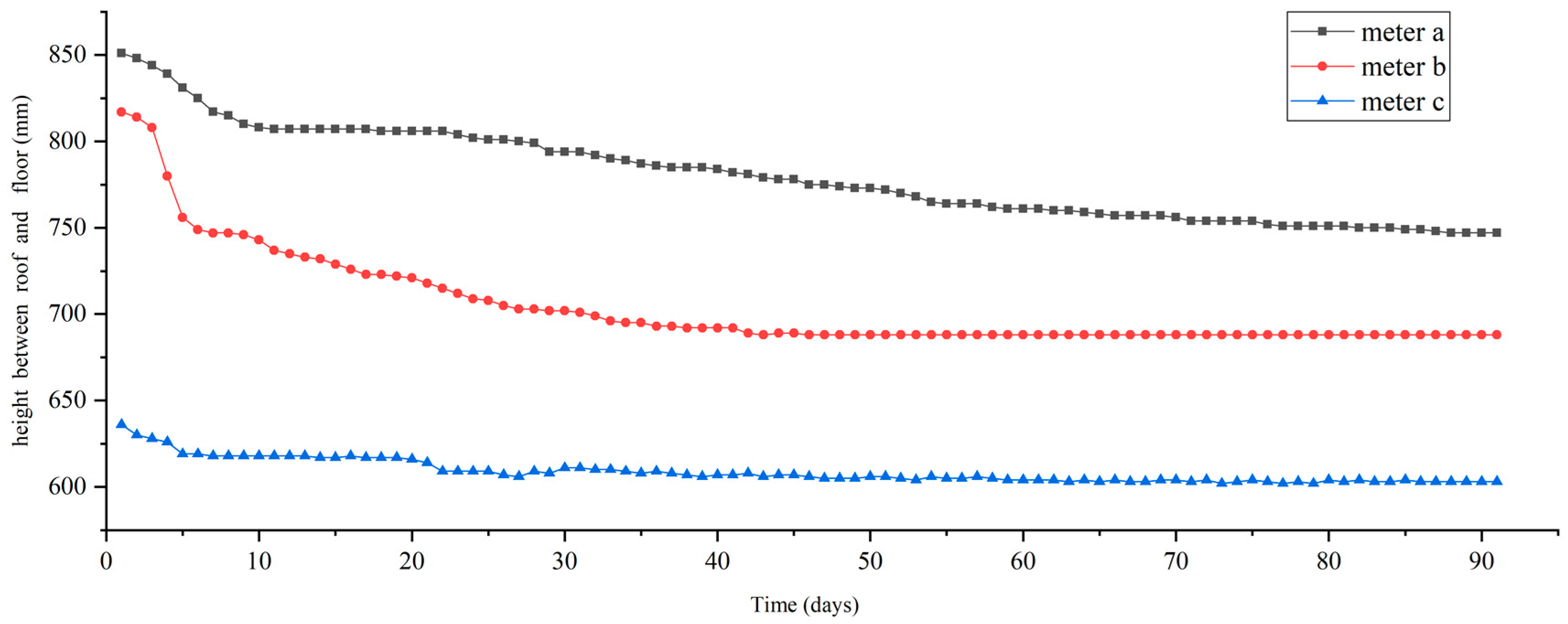
5.2. Roof-Floor Displacement (RFD) Monitoring in the Backfill Area
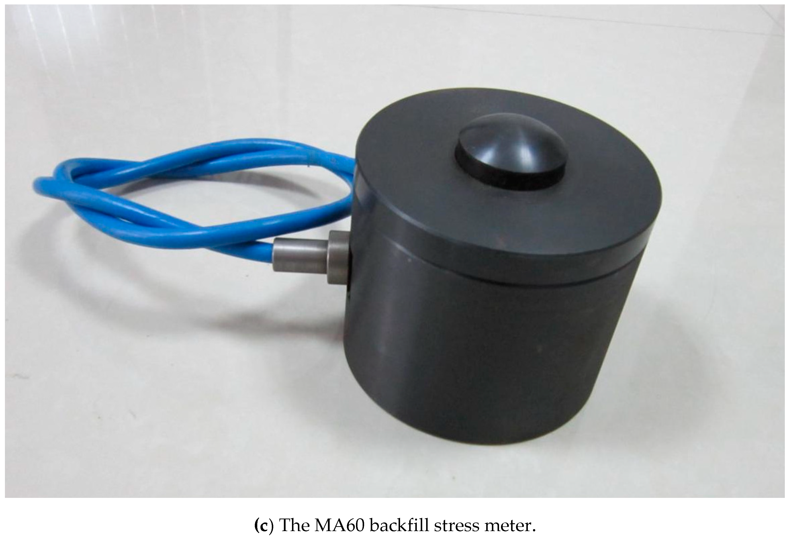
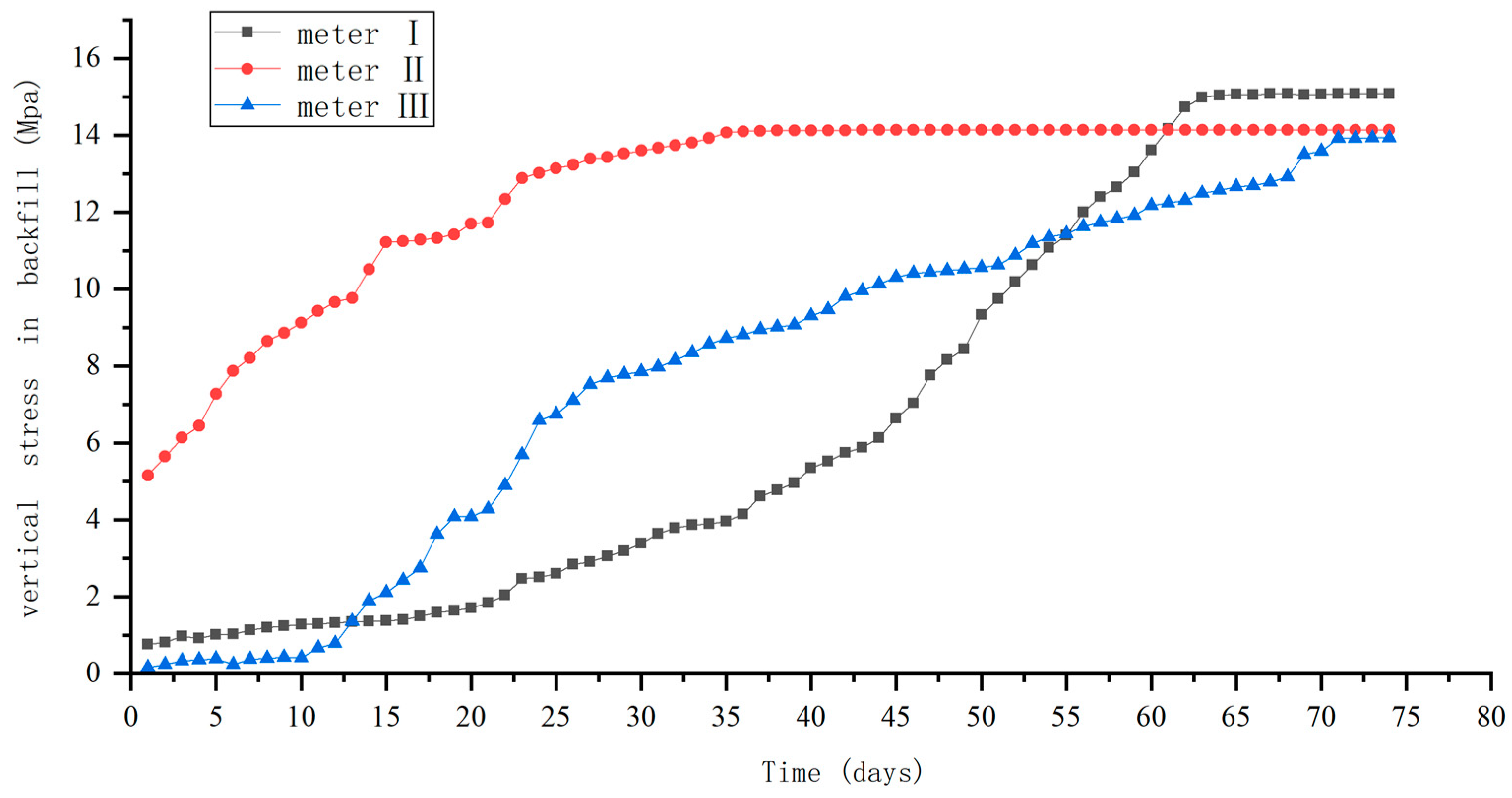
5.3. Variations of Vertical Stress in the Backfill Area
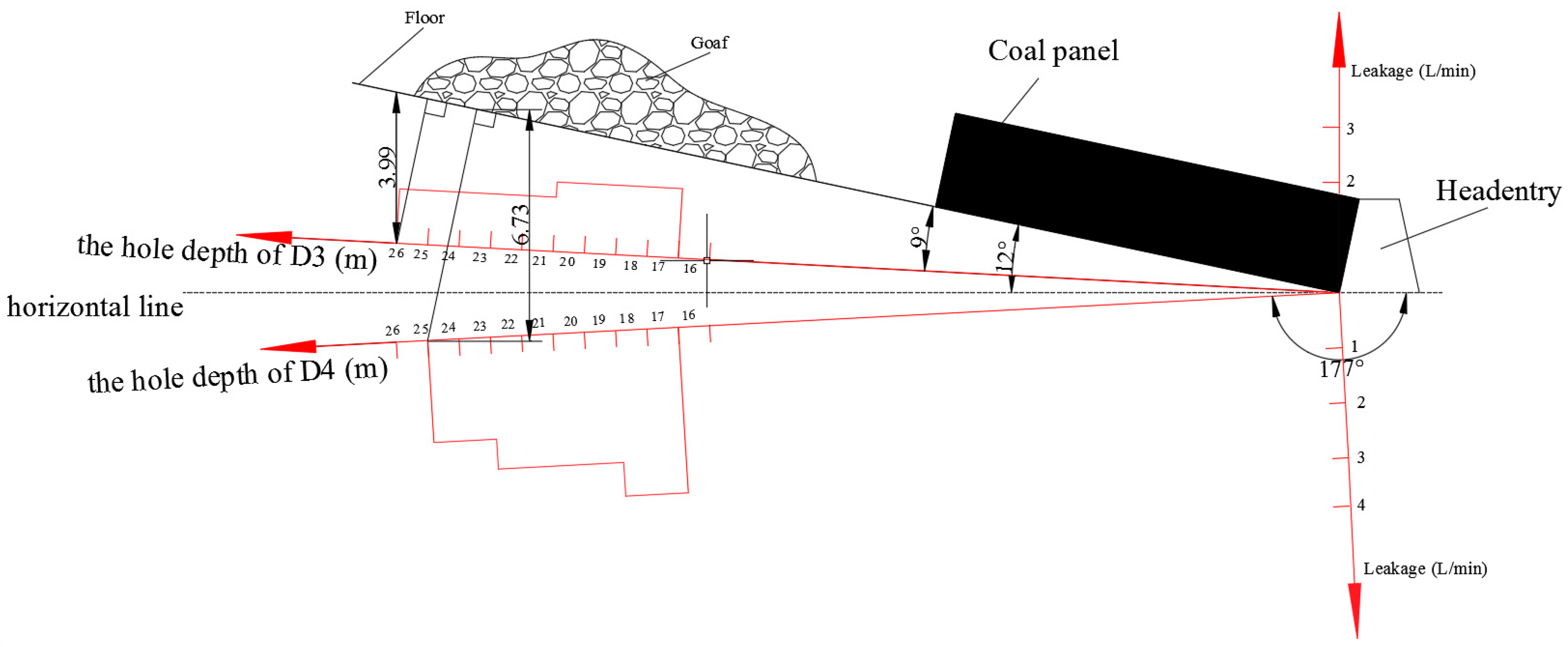
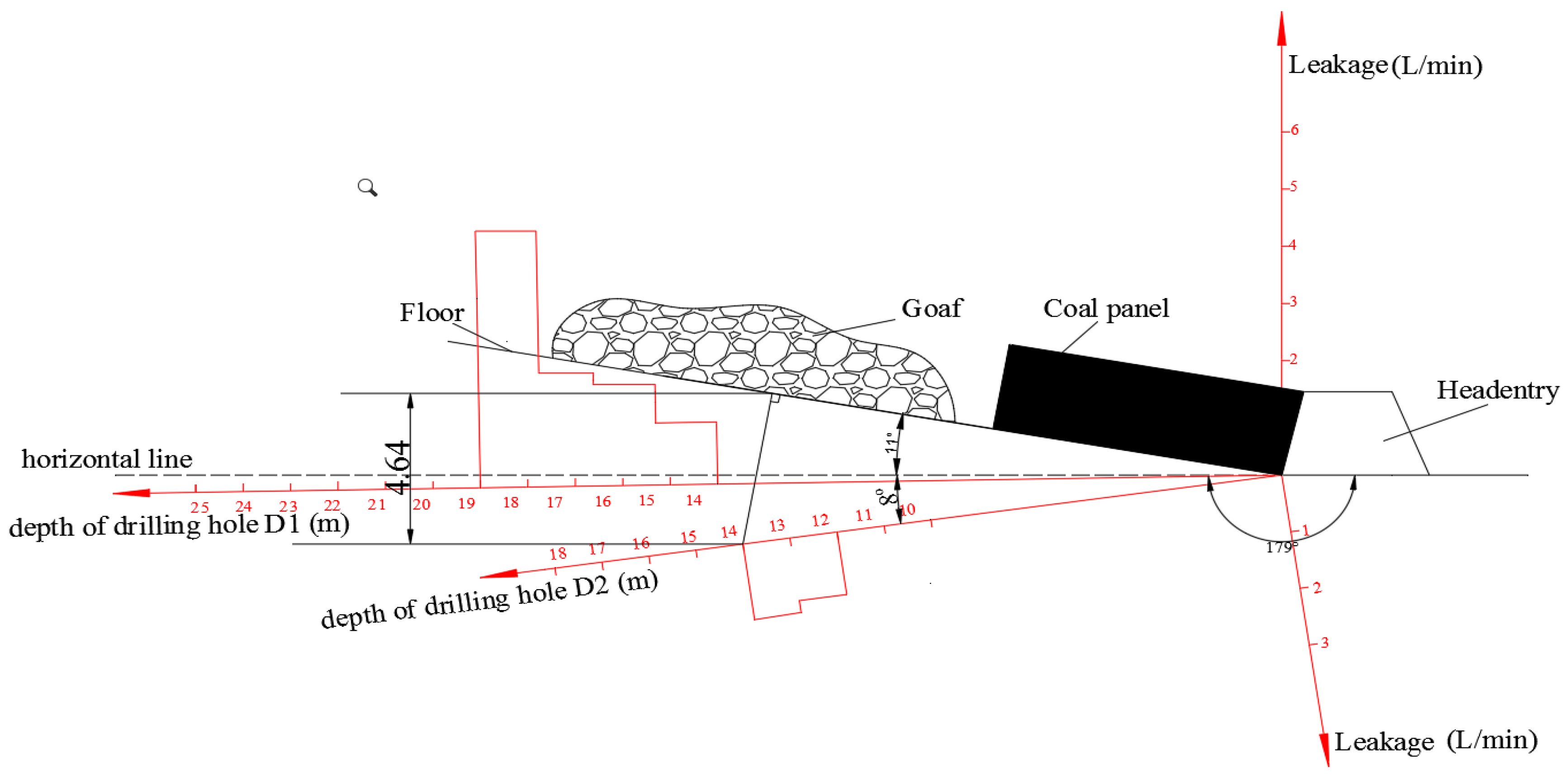
5.4. FFD in Backfill Mining
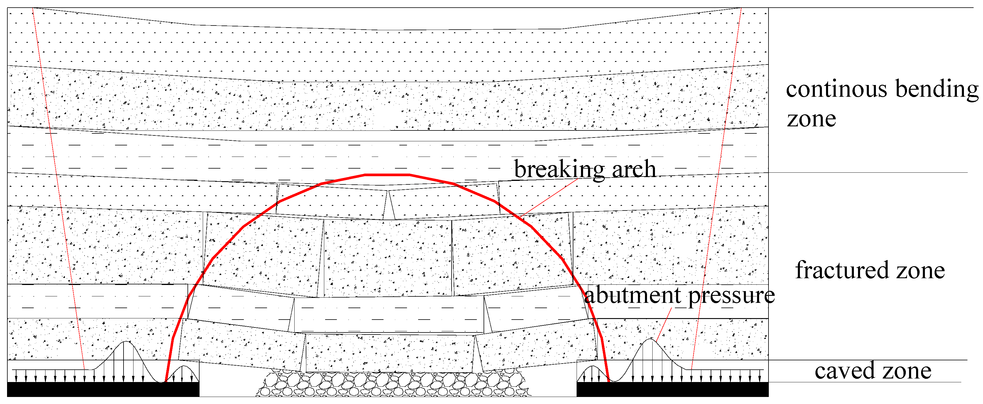
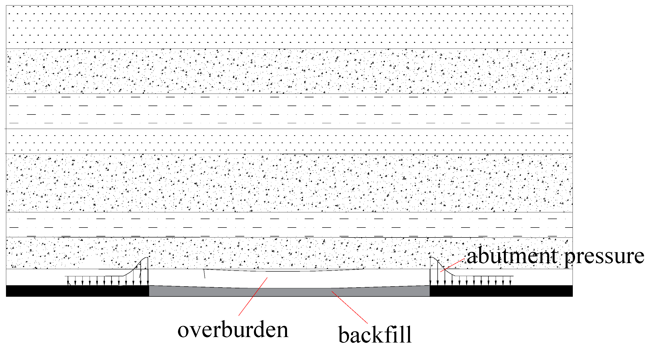
5.5. Differences Between Strata Movement Rule of Backfill Mining and Traditional Longwall Mining and its Effect on Water Inrush
6. Conclusions
Author Contributions
Funding
Conflicts of Interest
References
- Please, C.P.; Mason, D.P.; Khalique, C.M.; Ngnotchouye, J.M.T.; Hutchinson, A.J.; van der Merwe, J.N.; Yilmaz, H. Fracturing of an euler–bernoulli beam in coal mine pillar extraction. Int. J. Rock Mech. Min. Sci. 2013, 64, 132–138. [Google Scholar] [CrossRef]
- Singh, G.S.P.; Singh, U.K. A numerical modeling approach for assessment of progressive caving of strata and performance of hydraulic powered support in longwall workings. Comput. Geotech. 2009, 36, 1142–1156. [Google Scholar] [CrossRef]
- He, M.; Xie, H.; Peng, S. Study on rock mechanics in deep mining engineering. Chin. J. Rock Mech. Eng. 2005, 24, 2803–2813. [Google Scholar]
- Peng, S.S. Coal Mine Ground Control, 3rd ed.; Peng SS Publisher: Morgantown, WV, USA, 2008; pp. 229–237. [Google Scholar]
- Surinaidu, L.; Rao, V.V.S.G.; Ramesh, G. Assessment of groundwater inflows into Kuteshwar limestone mines through flow modeling study, Madhya Pradesh. India Arab. J. Geosci. 2013, 6, 1153–1161. [Google Scholar] [CrossRef]
- Tan, Y.L. Ground Pressure and Strata Control; China Coal Industry Publishing: Beijing, China, 2011. [Google Scholar]
- Zhang, X.; Lin, J.; Liu, J.; Li, F.; Pang, Z. Investigation of hydraulic-mechanical properties of paste backfill containing coal gangue-fly ash and its application in an underground coal mine. Energies 2017, 10, 1309. [Google Scholar] [CrossRef]
- Deng, X. Strata behavior in extra-thick coal seam mining with upward slicing backfilling technology. Int. J. Min. Sci. Technol. 2016, 26, 587–592. [Google Scholar] [CrossRef]
- Wu, D.; Sun, G.; Liu, Y. Modeling the thermo-hydro-chemical behavior of cemented coal gangue-fly ash backfill. Constr. Build. Mater. 2016, 111, 522–528. [Google Scholar] [CrossRef]
- Zhang, J.X.; Zhou, N.; Huang, Y.L.; Zhang, Q. Impact law of the bulk ratio of backfilling body to overlying strata movement in fully mechanized backfilling mining. J. Min. Sci. 2011, 47, 73–84. [Google Scholar] [CrossRef]
- Liu, C.Y.; Yang, P.J.; Hou, C.J. Movement law and stability analysis of overlaying strata under the condition of mining with filling. J. China Univ. Min. Technol. 2004, 3, 166–169. [Google Scholar]
- Liu, G.; Li, L.; Yang, X.; Guo, L. Numerical analysis of stress distribution in backfilled stopes considering interfaces between the backfill and rock walls. Int. J. Geomech. 2016, 17, 06016014. [Google Scholar] [CrossRef]
- Sivakugan, N.; Widisinghe, S.; Wang, V.Z. Vertical stress determination within backfilled mine stopes. Int. J. Geomech. 2014, 14, 06014011:1–06014011:5. [Google Scholar] [CrossRef]
- Liu, X.L.; Wang, S.Y. Mine water inrush forecasting during the mining under waters. Disaster Adv. 2012, 5, 876–881. [Google Scholar]
- Wang, X.Y.; Li, S.F.; Xu, G.Q.; Zhao, Y.Q.; Gao, Z.J.; Dong, D.L. Applied Hydrogeology; China University of Mining Press: Xuzhou, China, 2011. (In Chinese) [Google Scholar]
- Song, Z.Q. Practical Ground Pressure Controlling; China University of Mining & Technology Press: Xuzhou, China, 1998. [Google Scholar]
- Shi, Y. Simulation and Application of the Dynamic Structural Mechanics Model of Working Face; Shandong University of Science and Technology: Taian, China, 2001. (In Chinese) [Google Scholar]
- Tan, Y.L.; Liu, X.S.; Ning, J.G.; Tian, C.L. Front Abutment Pressure Concentration Forecast by Monitoring Cable-Forces in the Roof. Int. J. Rock Mech. Min. Sci. 2015, 77, 202–207. [Google Scholar] [CrossRef]
- Song, Z.; Hao, J. Study on water inrush from fault’s prevention and control theory. J. China Coal Soc. 2013, 38, 1511–1515. [Google Scholar]


| Serial Number | Index | Traditional Longwall Mining | Filling Mining |
|---|---|---|---|
| 1 | Overburdens movement scope | “Three zones” exist | “Three zones” do not exist |
| 2 | Overburdens movement form | Immediate roof caves | Immediate roof does not cave |
| 3 | Roof subsidence | Great | Small |
| 4 | Abutment pressure | High | Low |
| 5 | Plastic zone | Wide plastic zone | Narrow or no plastic zone |
© 2019 by the authors. Licensee MDPI, Basel, Switzerland. This article is an open access article distributed under the terms and conditions of the Creative Commons Attribution (CC BY) license (http://creativecommons.org/licenses/by/4.0/).
Share and Cite
Hao, J.; Shi, Y.; Lin, J.; Wang, X.; Xia, H. The Effects of Backfill Mining on Strata Movement Rule and Water Inrush: A Case Study. Processes 2019, 7, 66. https://doi.org/10.3390/pr7020066
Hao J, Shi Y, Lin J, Wang X, Xia H. The Effects of Backfill Mining on Strata Movement Rule and Water Inrush: A Case Study. Processes. 2019; 7(2):66. https://doi.org/10.3390/pr7020066
Chicago/Turabian StyleHao, Jian, Yongkui Shi, Jiahui Lin, Xin Wang, and Hongchun Xia. 2019. "The Effects of Backfill Mining on Strata Movement Rule and Water Inrush: A Case Study" Processes 7, no. 2: 66. https://doi.org/10.3390/pr7020066
APA StyleHao, J., Shi, Y., Lin, J., Wang, X., & Xia, H. (2019). The Effects of Backfill Mining on Strata Movement Rule and Water Inrush: A Case Study. Processes, 7(2), 66. https://doi.org/10.3390/pr7020066