1. Introduction
It has been more than twenty years since a new generation of functional operating fluids, named as ‘Nanofluids’ have been discovered. The colloids have been accomplished by adding nanometer-sized structures (size less than 100 nm), within the conventional single-phase fluids. The single-phase heat transfer liquids like water, sodium alginate, lubricants, engine oil, organic liquids (e.g., propylene and ethylene glycols, etc.) and polymeric solutions, seems deficient to intensify the heat transmission rate, in various engineering and industrial processes. The leading cause behind is the least effective thermal properties of the working fluids. Nano additives significantly boost the thermal properties of the single-phase fluids [
1]. In this regard, the pioneering work has been delivered by Choi [
2,
3], which significantly highlights the existence and effectiveness of tiny sized particles on the thermal efficiency of the single-phase heat transfer fluids. Later on, numerous research activities have been carried out by a number of scientists. Subsequently, a variety of models, related to the thermo-mechanical properties of nanofluids, have been introduced, for numerous industrial and practical situations. In this context, Maxwell [
4] announced a model that is based on the thermal conductivities of single-phase fluids along with the solid nanocomposites. Besides, this method deals explicitly with the spherical shaped tiny composites, whose volume concentration is assumed to be very small. Afterwards, a theoretical model has been developed by Bruggeman [
5], which usually encounters the relationships between the spheres shaped solid nanocomposites. In 1962, Hamilton and Crosser [
6] reformulated Maxwell’s model by introducing the shape factor. Further studies, in this field, reveal several mechanisms [
7,
8,
9,
10,
11] that can be helpful in improving the thermal efficiency of nanofluids.
Nanofluids have replaced the conventional single-phase heat transfer fluids in numerous applications including car radiators, oil recovery, aerospace engineering, lubrication, the system of photovoltaic and solar collectors, drug delivery, medicine, cooling of electronic systems, etc. During the last two decades, a number of research activities related to the preparation, classification, dispersion, modelling and rate of heat transfer due to convection, in the case of mono nanofluids, have been conducted, which makes a significant contribution in the existing literature [
1]. Recently, a novel subject of hybrid nanofluid, successfully caught the sights of worldwide researchers, due to their superior thermo-mechanical properties, when compared to monotype nanofluids. The hybrid composition has been accomplished by dispersing (i) a variety (two or more) of nanometer-sized particles in the single-phase liquids, and (ii) composite nanostructures in the single-phase heat transfer fluids. Thus, the process of hybridization successfully leads to the homogenous phase, which provides the physical and chemical bonding of several materials at one place. The purpose of hybridity is to boost the characteristic features, like thermomechanical, hydrodynamic and heat transport properties of traditionally used fluids [
12,
13].
The innovative concept of hybrid nanofluid has a profound impact on the global research community and consequently, the research activities, in this area, have shown immense progress, during the last few years [
13]. By opting the novel idea of material design, Niihara [
14] incorporated the nanometer-sized particles within the host fluid and hence, gave a detailed description related to the improvement in the physical and chemical characteristics of the host fluid. Jana et al. [
15] introduced the mono and hybrid type nanofluids to inspect the thermal efficiency of the common fluid. By considering the two-step procedure, Suresh et al. [
16] critically scrutinized the behavior of
hybrid nanofluid. They have provided an experimental result, which exhibits an increment in the viscosity along with the thermal conductivity of the host fluid. In another study [
17], they have presented a brief explanation regarding the heat transport properties of
hybrid nanofluid. By making use of a numerical scheme, Balla et al. [
18] investigated the augmentation in the heat transport mechanism, for hybrid
nanofluid. By taking the different shapes of nanocomposites into consideration, Saba et al. [
19] explored the thermophysical properties of
based hybrid
nanofluid in an asymmetric channel. Recently, Ahmed et al. [
20] presents a study, comprising the combined effects of nonlinear thermal radiation and chemical reaction, on the squeezing flow of
based hybrid
nanofluid between two Riga plates.
In recent past years, the worldwide-renowned scientists have paid immense attention to the study of the flows over flat expanding surfaces. These kinds of flows have paved a way in many industrial and engineering processes such as paper manufacturing, polymer sheets, production of plastic and rubber sheets, wire coating, glass fibers, food manufacturing processes, etc. In this context, Sakiadis [
21] was a pioneer, who firstly introduced the concept of flows of boundary layer nature, over a flat expanding surface. Then, his concept has been utilized by Crane [
22], who considered the flow due to the linear stretching of the flat surface. These pioneering works then paved the way for the worldwide scientists, to discover the new ideas related to this interesting subject. Later, Gupta and Gupta [
23] presented a remarkable work by considering the flow behavior over a spongy surface. After the pioneering work, to date, many scientists have encountered a variety of flow situations related to the study of the flat stretching surface [
24,
25,
26] and the references therein.
In modern adhesive cutting-edge technology, the stretching of curved surfaces has found a way in many practical applications, for example, in electronics, transportation, etc. However, the subject related to the flow caused by the stretching of the curved surface has been hardly attended. In 2010, Sajid et al. [
27], for the very first time, scrutinized the viscid flow over a curved expanding surface, which can be stretched with the linear velocity. They have also revealed through their study that the thickness of the boundary layer boosts in the case of a curved stretching surface when compared with the flat stretching surface. By taking the magnetohydrodynamic effects into account, Hayat et al. [
28] examined the nonlinear thermal radiative effects, on the flow of nanofluid, with copper and silver are taken as nano additives, over the curved stretching surface. They have also analyzed the heat transport mechanism due to the convective process. By employing carbon nanotubes in the host fluid, Saba and her fellows [
29] briefly analyzed the flow behavior over a curved surface. They have also examined the system of heat transport under the action of radiative effects together with the internal generation of heat. Lu et al. [
30] investigated the hybrid nano liquid flow under the influence of various embedded factors like a magnetic field, nonlinear thermal radiation and heat absorption/generation. They have also inspected the mass and heat transport phenomena during their study.
Heat radiation is a procedure of transferring internal energy via electromagnetic waves. The infrared region comprises all those objects, from the earth’s surface, that emits the radiative energy. The thermal radiation has a wide range of applications such as glass manufacturing, polymer processing, solar power plant, thermal storage compounds, electrical power production, nuclear power technology and numerous industrial areas. Magnetohydrodynamics characterizes the flow behavior of fluids, possessing the electrical conducting properties, under the action of an externally applied magnetic field. Numerous engineering and industrial applications including power generators, pumps, heat exchangers, accelerators and the cooling reactors involve the magnetohydrodynamics systems. Reddy [
31] employed the magnetohydrodynamics along with thermal radiative effects, to briefly discussed the behavior of a nanofluid flow, over a linearly stretching surface. The impact of radiation and externally applied magnetic field on the nanofluids over a nonlinear stretching surface has been analyzed by Poornima and Reddy [
32]. Some other studies comprising the magnetohydrodynamics along with thermal radiative effects can be found in [
33,
34] and the references therein.
On reviewing the existing literature, copious research activities have been found on the subject of nanofluids, over a flat stretchable surface; however, the articles related to the curved expanding surfaces are limited in number. This number gets even narrower, when the topic of a hybrid nanofluid, over a curved stretching surface, came under discussion. Therefore, the main concern of this article is to discuss the sodium alginate based hybrid nanofluid, over a stretchable curved surface. The whole analysis has been carried out with additional factors such as nonlinear thermal radiation, magnetohydrodynamics and chemical reaction effects. Heat and mass transport mechanisms have also been analyzed in details. Numerical results for the envisioned model have been developed by implementing a numerical recipe, so-called RungeKuttaFehlberg algorithm accompanied by the shooting technique. The graphical simulation along with a detail physical description has also been provided, that significantly highlights the traits of various meaningful emerging entities on the involved distributions.
3. Problem Formulation in Curvilinear Coordinates
A time-independent, incompressible, laminar flow of sodium alginate
based
hybrid nanofluid, moving over a curved surface, at
, has been under consideration (see
Figure 1). The curved surface endures a linear stretchable velocity
in the horizontal
direction, while, a boundary layer has been established by the fluid, in the radial
direction. The curvy shape of the surface can be determined via
, the distance between the surface to the origin, and the curved surface become flat, for an infinitely large radius of curvature
. The constant magnetic field, with strength
, is also employed, which acts normal to the fluid flow, i.e., in the radial
direction. By owing the assumption of small Reynolds number, all the impacts due to electric and induced magnetic fields are neglected. Furthermore, heat and mass transport mechanisms are examined through nonlinear thermal radiation and chemical reaction. It is further pertinent to mention that the temperature along with concentration are simultaneously represented by
and
, while,
and
corresponds to the temperature and concentration of free streamlines with the assumptions
and
.
Under the assumptions as mentioned above, the governing equations, including the continuity, momentum, temperature and concentration profiles, relevant to the current boundary layer flow situation, can be mathematically expressed as follows [
28,
30]:
where
.
and
simultaneously depict the horizontal
and radial
velocity components.
,
and
symbolizes the density, electrical conductivity and kinematic viscosity for the hybrid nanofluid, respectively. The heat capacity, thermal conductivity and thermal diffusivity, in the case of hybrid nanofluid, are respectively denoted by
,
and
. Moreover,
stands for the pressure term, while, the temperature and concentration are simultaneously represented by
and
. The radiative term is indicated by
, while
illustrates the chemical reaction.
The relevant boundary conditions are defined as [
28,
30]:
The terminology for radiative heat transport can be estimated via Rosseland approximation [
37], which is given as follows:
where,
signifies the Stefan–Boltzmann constant, while, the coefficient for mean absorption is characterized by
. Therefore, by making use of Equation (24), the energy equation (Equation (21)) can be put into the following form:
Now, by considering the following similarity variables:
The equation for mass conservation (Equation (18)) is automatically verified; however, the Equations (19), (20), (22) and (25), can be written, in the dimensionless form, as:
The associated boundary conditions, after the implementation of Equation (26), can be expressed by the following dimensionless form:
The dimensionless quantities, arising in the above set of Equations (27)–(30), can be defined as:
where the dimensionless radius of curvature is denoted by
.
represents the magnetic parameter, while, the radiation and temperature ratio parameters are simultaneously symbolized by
and
.
signifies the chemical reaction parameter. The Schmidt and Prandtl numbers are characterized by
and
, respectively.
By excluding the pressure term from Equations (27) and (28), we get
Afterwards, the pressure
can be evaluated from Equation (28), which is given as:
The quantities that can be practically useful in many engineering and industrial situations are, surface drag coefficient
, the local Nusselt
and Sherwood
numbers. Their respective mathematical expressions are given as:
where the wall shear stress is symbolized by
, while
and
simultaneously represents the rate of heat and mass transports at the wall. They can be mathematically specified as:
By making use of Equations (26) and (31) into Equation (30), the respective dimensionless forms, for the surface drag coefficient
, the local Nusselt
and Sherwood
numbers are:
where,
expresses the local Reynolds number.
5. Physical Explanation of Results
This segment is designed to scrutinize the impact of various emerging parameters on the velocity and pressure distribution. The temperature, together with concentration profiles, has also been considered. For the said purpose, the graphical simulations, along with the detailed description, have been presented. The graphical pictures have been plotted for both nanofluid and sodium alginate based hybrid nanofluid. The main emphasis is to give the comparative study related to both types (mono and hybrid) of nanofluids. In the upcoming pictures, solid lines are dedicated to the outcomes of sodium alginate based hybrid nanofluid, while the results for nanofluid has been presented via dashed lines.
Figure 2,
Figure 3 and
Figure 4 have been sketched for the velocity distribution, by considering the distinct values of emerging entities like the dimensionless radius of curvature
, Magnetic parameter
and the volume fractions for both mono and hybrid nanofluids (
and
), respectively. From
Figure 2, a definite rise in the horizontal, as well as vertical components of velocity, have been witnessed with the decreasing values of
(or increasing the dimensionless curvature). This rising behavior is more prominent, in the case of the vertical velocity as compared to the horizontal velocity. The physical reasoning behind this fact is the existence of the centrifugal force, which the fluid, over a curved stretching surface, may encounter while moving along the circular path. In actual, the curvature of the surface is mainly responsible for the production of the centrifugal force, corresponding to the centripetal acceleration, whose direction is normal to the center of curvature to maintain the circular flow of the fluid. As a result of this centrifugal force, an additional disturbance named as the secondary wave has been produced, whose resulting effects are then combined with the effects of primary wave, which is caused by the surface expansion. Since, the direction of the centrifugal force is normal to the surface, therefore, a significant impact on the vertical velocity
has been recorded. However, the horizontal velocity
experiences a small increment. In the limiting case of infinitely large radius of curvature
, the curved surface turned out to be a flat surface and consequently, the centrifugal force disappears. In this situation, the net effect on the flow is due to the primary flow caused by the stretched surface alone. Moreover, it was observed that the sodium alginate
based
hybrid nanofluid exhibited low velocity profiles along the
and
direction, when compared to the
nanofluid.
The influence of Magnetic parameter
on the normal along with horizontal components of velocity have been presented in
Figure 3a,b. A decline in the velocity fields (
and
) for both
nanofluid and sodium alginate
based hybrid
nanofluid has been perceived, with the growing values of the magnetic parameter
. The cause behind is the development of the Lorentz forces, due to the applied magnetic field, inside an electrically conducting fluid. These forces act like a resistive force, which in turn suppresses the bulk motion of the fluid and hence, the velocity, together with the thickness of momentum boundary layer, of the fluid exhibit a declining behavior [
28,
38,
39].
Figure 4a,b has been designed to see the performance of nanoparticles volume fractions (
and
) on the velocity profiles (
and
), respectively. Both the velocity modules,
and
, shows a declinatory mechanism with the increasing values of volume fractions (
and
), for both
nanofluid and sodium alginate
based
hybrid nanofluid. In actual, the augmentation in the nanocomposites volumetric fractions mainly is responsible for the production of viscous effects within the fluid. These effects provide resistance for the further movement of the fluid and as a result, decreases the velocity of the fluid. This particular phenomenon has been detected for both
nanofluid and sodium alginate
based
hybrid nanofluid. Moreover, it has been noticed that the
nanofluid has been least affected by the inclusion of nanocomposites volumetric fractions as compared to sodium alginate
based
hybrid nanofluid, which is due to the lower density values of the
nanofluid.
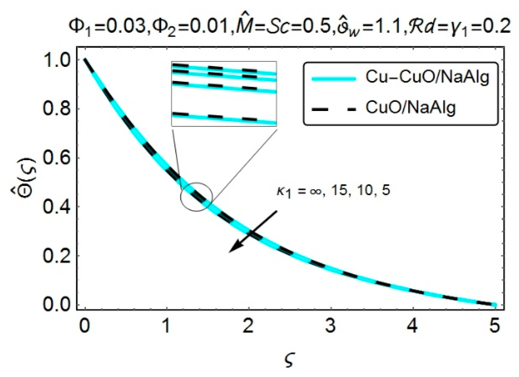
Figure 5,
Figure 6,
Figure 7,
Figure 8 and
Figure 9 have been designed to visualize the impact of various meaningful emerging entities like the dimensionless radius of curvature
, Magnetic parameter
, the volume fractions for both mono and hybrid nanofluids (
and
), Radiation parameter
and the temperature difference parameter
on the temperature distribution
. An upsurge in the temperature distribution
, for both
nanofluid and sodium alginate
based
hybrid nanofluid has been noticed with the decreasing values of
(see
Figure 5). The main cause behind is the heat conduction process, which grows when the curvature is employed in the flat expanding surface. From
Figure 6, one can see an increment in the temperature behavior with the growing values of magnetic parameter
. The applied magnetic field develops the Lorentz forces within the fluid, which behaves like a resistive force and eventually the friction effects have been recorded inside the fluid. These effects ultimately produce the heat, and consequently, an intensification in the temperature profile has been achieved [
28,
38,
39]. Moreover, it is noteworthy that the
hybrid nanofluid exhibits a higher temperature profile as compared to
nanofluid.
The role of increasing nanocomposites volumetric fractions on the temperature profiles was displayed in
Figure 7. It was noted that the inclusion of nano-sized structures with variable volumetric fractions contributes to the enhancement of the temperature of the fluid. The physical reasoning behind this fact is the intensification in the thermal conductive properties of the host fluid. Therefore, it is understood that the temperature gets its maximum values in the case of
hybrid nanofluid, which can be seen from
Figure 7.
Figure 8 portrays the impact of the radiation parameter
on the temperature profile. The increment in the radiation parameter significantly supports the augmentation in the temperature distribution. The actual reason is the drop in the mean absorption coefficient, which considerably improves the radiative effects inside the fluid and consequently, boosts the temperature of the fluid. Besides, this phenomenon has been accomplished for both
nanofluid and sodium alginate
based
hybrid nanofluid.
The effectiveness of temperature difference parameter
on the temperature distribution, has been offered via
Figure 9. A rise in temperature, for both
nanofluid and sodium alginate
based
hybrid nanofluid has been chronicled with the growing values of
. The augmentation in
greatly supports the improvement in temperature differences and hence, an enhancement in temperature has been perceived. Besides, the
hybrid nanofluid reveals the maximum temperature values.
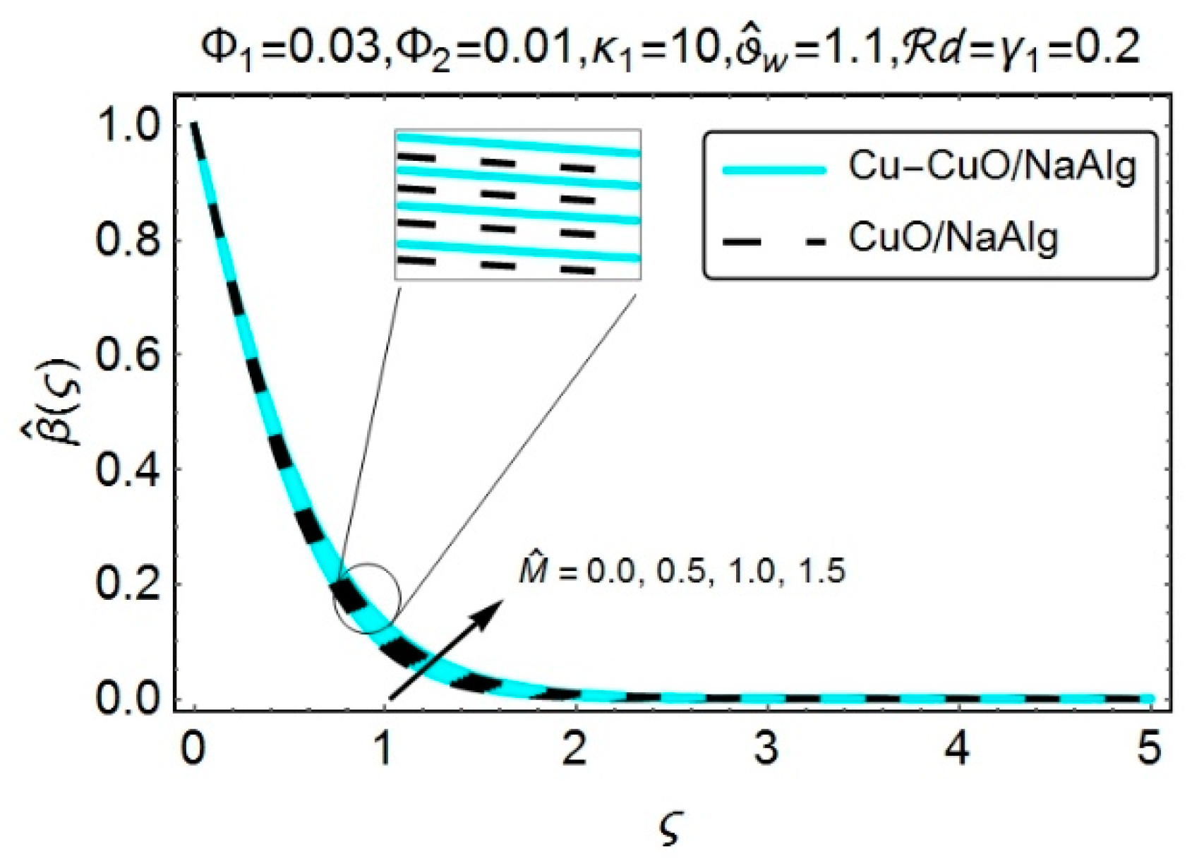
Figure 10,
Figure 11,
Figure 12,
Figure 13 and
Figure 14 provides the graphical simulation for the concentration profile
, by taking the effects of various embedded entities like the dimensionless radius of curvature
, magnetic parameter
, the volume fractions for both mono and hybrid nanofluids (
and
), Schmidt number
and the chemical reaction parameter
into consideration. It can be seen from
Figure 10 that the reduction in the concentration profile
has been perceived with the decreasing
. A drop in the dimensionless radius of curvature
supports the curvilinear nature of the surface. As the curviness of the surface increases, the kinematic viscosity decreases. So, the density along with the mass of the host fluid experiences a decline, and hence, the concentration profile reduces. The increment in the magnetic parameter
significantly takes part in enhancing the concentration profile, for both
nanofluid and sodium alginate
based
hybrid nanofluid (see
Figure 11). In fact, the implementation of magnetic field yields the Lorentz forces, which is responsible for the production of a significant amount of heat inside the fluid. This, in actual, slows down the process of heat and mass transfer from the wall and hence, boosts the temperature as well as the concentration profiles. The inset pictures also revealed the fact that the
nanofluid possessed maximum concentration values.
Figure 12 has been plotted to see the impact of nanocomposites volumetric fractions on the concentration profile
. It is notable that by increasing the volumetric fraction of nano additives, the decrement in the solute concentration was perceived. Besides, the concentration profile possessed lower values for sodium alginate
based
hybrid nanofluid. The impact of Schmidt number
on the concentration profile, for both
nanofluid and sodium alginate
based
hybrid nanofluid has been depicted in
Figure 13. The higher estimated values of Schmidt number
considerably lessened the concentration of the species. As
indicates the ratio of viscous diffusion rate and the mass diffusion rate. Thus, for growing values of
, the rate of mass diffusion decayed, and hence the concentration field endured an absolute decline.
Figure 14 has been offered to display the influence of chemical reaction parameter
on the concentration field
. It is notable that the growing values of chemical reaction parameter
significantly reduced the concentration profile
. The physical explanation of this behavior is that the increment in
implies the destructive chemical reaction at a higher rate, which, in turn, effectively dissolves or terminates the liquid species. Hence, a decay in the concentration profile, for both
nanofluid and sodium alginate
based
hybrid nanofluid was accomplished.
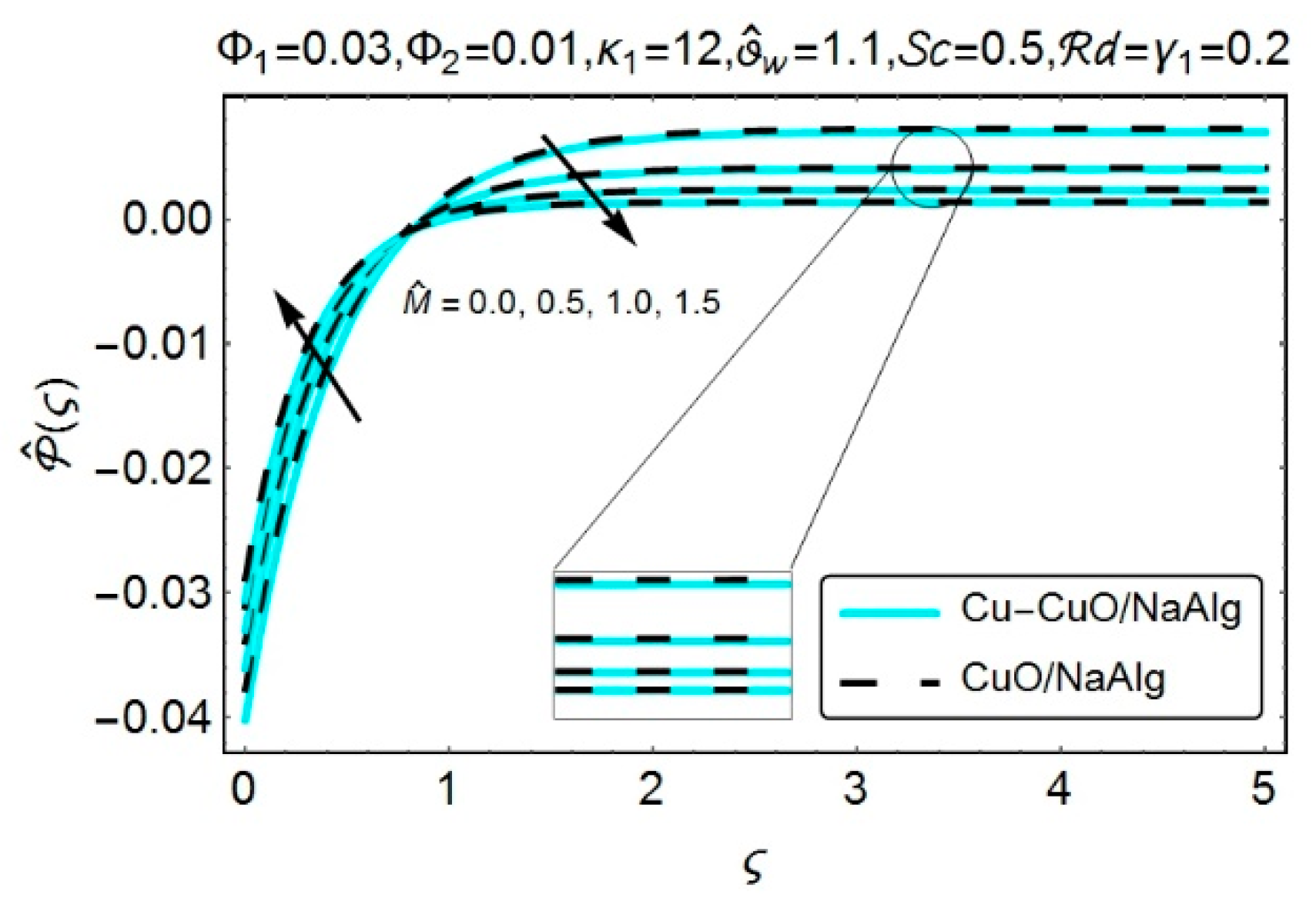
Figure 15,
Figure 16 and
Figure 17 have been designed to inspect the behavior of pressure profile under the impact of the dimensionless radius of curvature
, magnetic parameter
, the volume fractions for both mono and hybrid nanofluids (
and
).
Figure 15 demonstrates the impact of the dimensionless radius of curvature
on the pressure distribution. A drop in the dimensionless radius of curvature
, means that the curviness of the surface increases, which significantly supported the growing absolute values of pressure and this phenomenon was quite prominent inside the boundary layer. However, the effectiveness of the pressure profile seemed to be negligible as we moved away from the curved surface. The physical aspect behind this behavior was that as the distance from the surface increased, the streamlines, for both
nanofluid and sodium alginate
based
hybrid nanofluid, acted in the same way as they could be noticed in the case of flat dilating surface. In the limiting case of an infinitely large radius of curvature
, which corresponds to the flat stretching surface, consistent behavior of the pressure was recorded not only inside but also the outside of the boundary layer. However, in the case of a stretchable curved surface, the effectiveness of pressure could not be ignored, as it proved its dominancy inside the boundary layer.
Figure 16 provides the pictorial view of the pressure profile due to the varying value of the magnetic parameter
. It is noteworthy that, at the initial stage, the absolute values of the pressure distribution exhibited a declining behavior with the growing values of the magnetic parameter. However, reversed behavior was perceived after
. The same behavior was recorded for the varying values of the dimensionless radius of curvature
. As the curviness was introduced in the surface, the pressure did not show a consistent behavior inside and outside the boundary layer. Moreover, the inset pictures (from
Figure 15 and
Figure 16) revealed the fact that, in the case of
nanofluid, the pressure distribution exhibited a dominating behavior, outside the boundary layer, as compared to the sodium alginate
based
hybrid nanofluid.
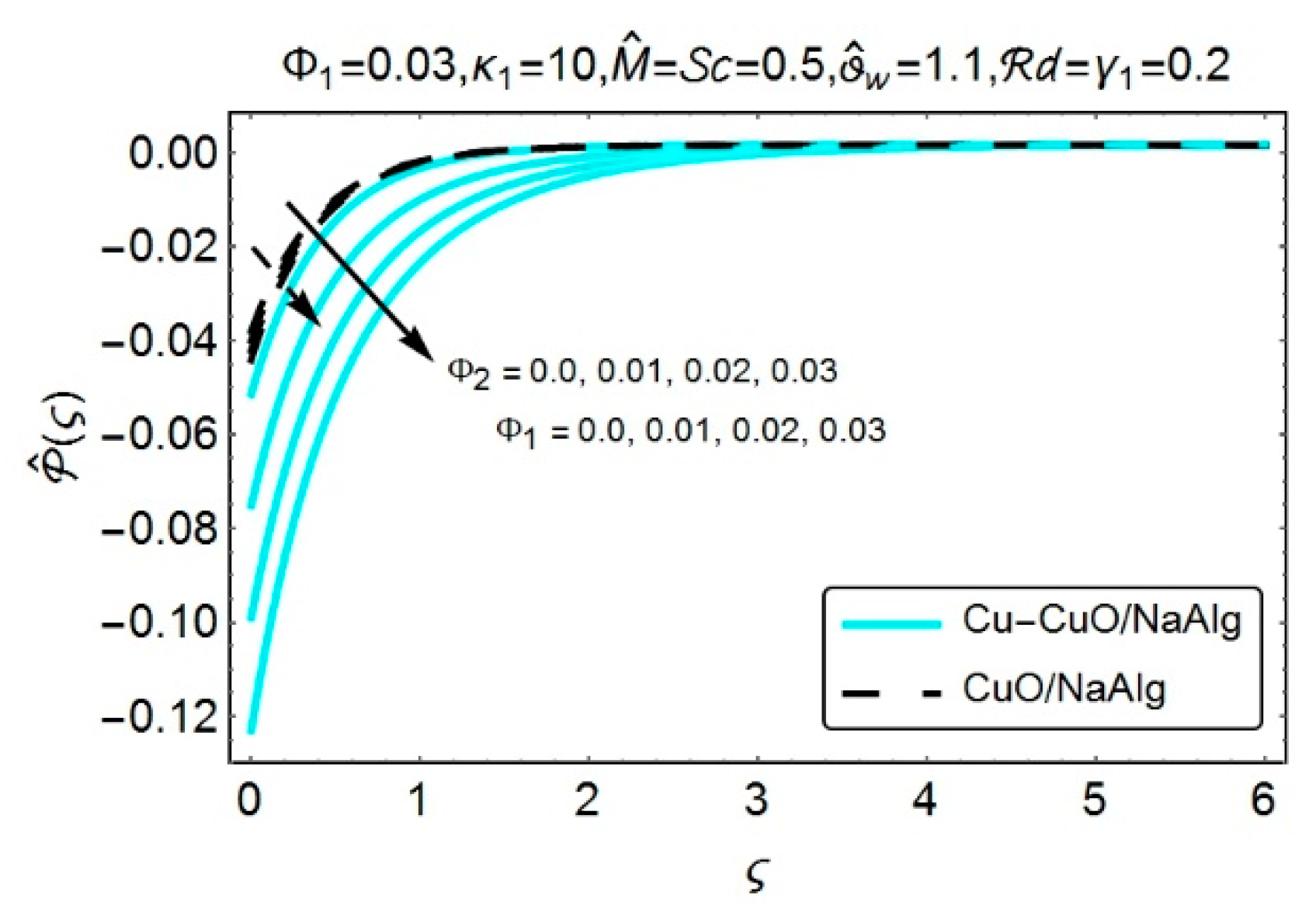
Figure 17 elucidates the impact of volumetric fraction of nano-sized structures (
and
) on the pressure profile. The plot was designed for both
nanofluid and sodium alginate
based
hybrid nanofluid. The increasing nanocomposites volumetric fractions (
and
), successfully contributed to the growing absolute values for the pressure profile. Moreover, the
nanofluid presented the lower absolute values of pressure profile, inside the boundary layer, when compared to
hybrid nanofluid.
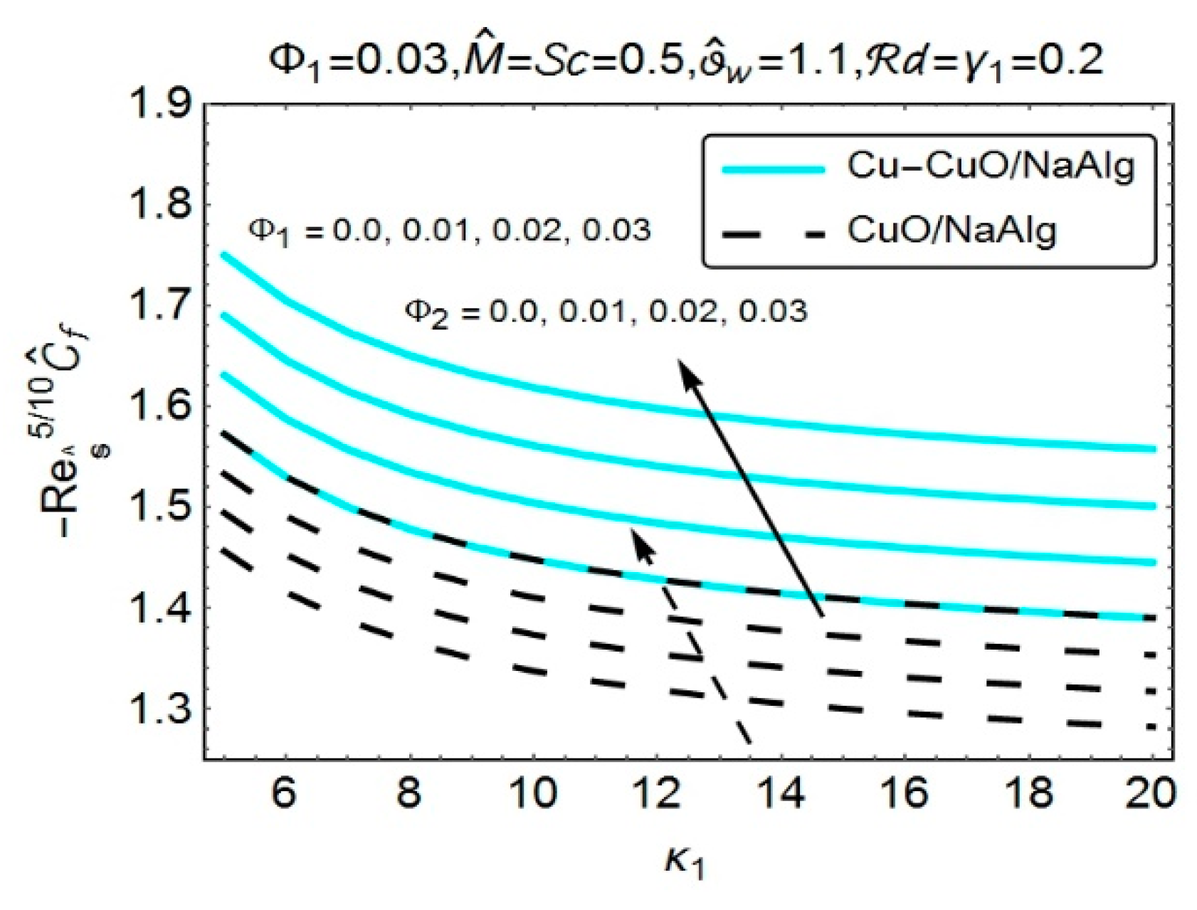
Figure 18 and
Figure 19 have been painted to visualize the consequences of various meaningful emerging variables like the dimensionless radius of curvature
, magnetic parameter
, the volume fractions for both mono and hybrid nanofluids (
and
) on the coefficient of skin friction drag. It can be elucidated from
Figure 18 that the coefficient for skin friction, for both
nanofluid and sodium alginate
based
hybrid nanofluid, experienced a decline with the growing values of the dimensionless radius of curvature
. This means that the surface drag force needs to be intensified when the curviness has been employed in the flat stretching surface. On the contrary, the magnetic parameter
displayed a reversed behavior and the surface drag force exhibits an increment with the growing values of magnetic parameter
. The inclusion of nanometer-sized structures within the fluid also displayed an improvement in the surface drag force, and this can be observed for both mono and hybrid nanofluids (see
Figure 19). Moreover, it was evident from both
Figure 18 and
Figure 19 that the surface drag force, in the case of
hybrid nanofluid, displayed its dominancy when compared to the
nanofluid.
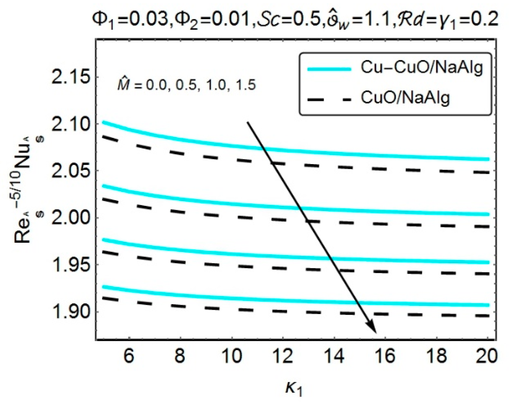
In order to assess the behavior of the local rate of heat transfer, due to varying values of the dimensionless radius of curvature
, magnetic parameter
, the volume fractions for both mono and hybrid nanofluids (
and
), radiation parameter
and the temperature difference parameter
.
Figure 20,
Figure 21 and
Figure 22 has been painted. The rate with which heat transfers, from the surface of the curved sheet, exhibited a declinatory behavior, as the curviness of the surface tended to the flatness of the surface (see
Figure 20), and this behavior was recorded for both mono and hybrid nanofluids. It means that the rate, with which surface’s heat transmits, seems to be quite prominent in the case of the curved stretching surface. Besides, from
Figure 20, the heat transfer rate displays a similar declining behavior with the increasing magnetic variable
. Since the development of Lorentz forces, due to externally applied magnetic field, generates the friction effects inside the fluid, which in turn raises the temperature of the fluid and hence, slows down the process of transferring the heat from the surface. The inclusion of nanometer-sized structures (
and
), with different volume fractions, plays a vital role in enhancing the heat transfer rate, and it can be easily figured out from
Figure 21. Physically, the addition of nanometer-sized particles enriches the thermal properties of the host fluid, and as a result, the improvement in the heat-conducting properties is quite obvious. Moreover, the heat flux rate shows its proficiency in the case of
hybrid nanofluid, which was mainly due to the existence of higher thermal conducting values as compared to
nanofluid.
Figure 22 highlights the effects of radiative variable
and the temperature difference variable
on the local rate of heat flux and the results were calculated, by considering both mono and hybrid nanofluids. The figure provided evidence that the radiative variable
played a vital role in extensively transferring the heat from the system. The temperature difference variable
also supported the process of heat flux, and this behavior was observed for both mono and hybrid nanofluids. Furthermore, the
nanofluid depicted a lower heat transfer rate as compared to the
hybrid nanofluid.
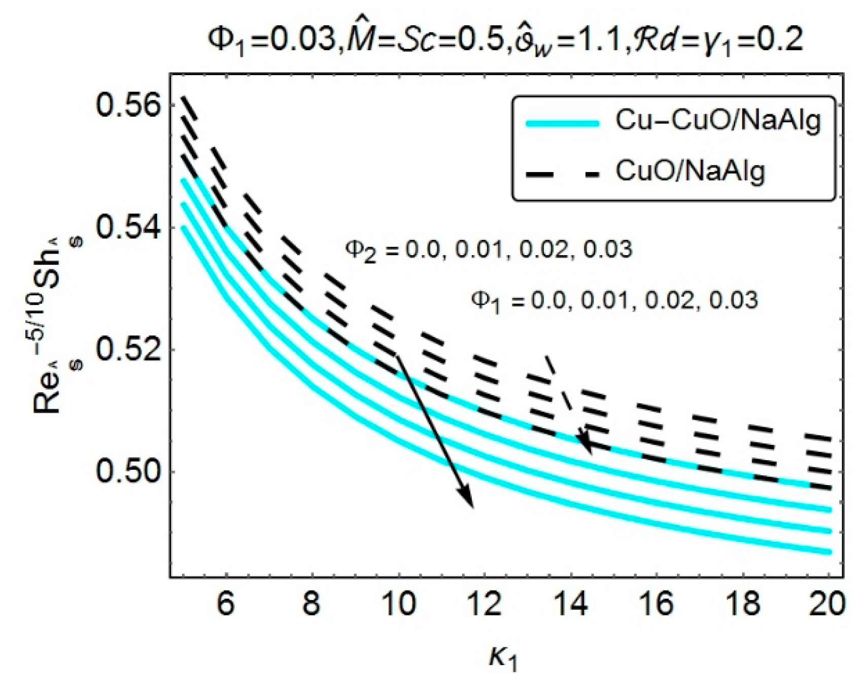
Figure 23,
Figure 24 and
Figure 25 have been designed to see the impact of the dimensionless radius of curvature
, magnetic parameter
, the volume fractions for both mono and hybrid nanofluids (
and
), Schmidt number
and the chemical reaction parameter
, on the local rate of mass transfer. A declinatory behavior has been perceived for the local rate of heat transfer, with the growing values of the dimensionless radius of curvature
(see
Figure 23). This behavior was noted for both mono and hybrid nanofluids. Thus, it could be concluded that the rate, with which mass transfers, exhibited its dominancy in the case of a stretchable curved surface. The mass transferring rate behaved in a decreasing manner with the increasing magnetic variable
. The magnetic field was responsible for the development of the Lorentz forces, which could extensively heat up the fluid. As a result, the temperature, along with the concentration profiles, increased, and thus the process of mass transfer decreased. The dispersion of nanometer-sized particles (
and
), with variable volume fractions, could certainly take part in slowing down the mass transferring process, and this could be easily detected from
Figure 24. Moreover, the
nanofluid illustrates an increment in the process of mass transfer, as compared to the
hybrid nanofluid.
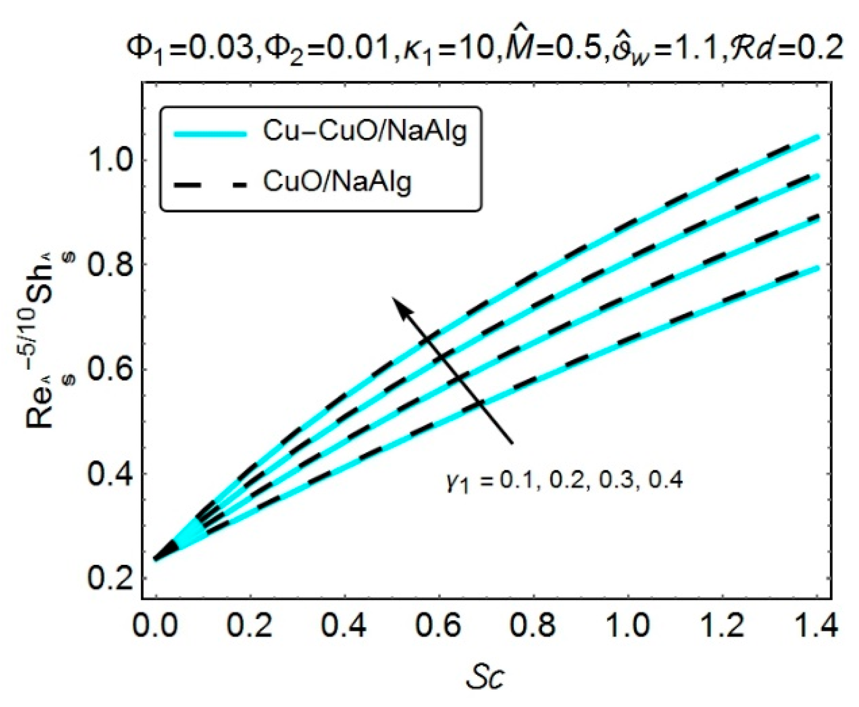
Figure 25 has been painted to assess the influence of Schmidt number
and the chemical reaction parameter
, on the local rate of mass transfer. It can be noticeable that the mass transferring process has been significantly improved, with the growing values of Schmidt number
. Almost a similar behavior has been detected with the increasing values of chemical reaction variable
. Moreover, the improvement in the rate of mass transfer was recorded for
nanofluid as well as the
hybrid nanofluid.
To validate the existence of numerical procedure, a comparison of the numerical results, for the surface drag coefficient
, with the previously existing outcomes of [
24,
26,
39], [
24] has been presented in
Table 2. A good match, among the outcomes, can be visible from the table for varying values of dimensionless radius of curvature
and magnetic parameter
.

 ,
, 


