Abstract
The physical and chemical processes in the raceway zone of the COREX melter–gasifier express are similar to those inside the blast furnace. Based on the research achievements on blast furnaces, the unsteady numerical simulation of a gas-solid two-phase in the raceway was carried out by using computational fluid software. The formation process of the raceway in the COREX melter–gasifier was simulated. The shape and size of the raceway were obtained. Then, the effect of gas flow on the depth and height of the raceway was analyzed in this paper.
1. Introduction
COREX is the world’s first commercially established and industrially proven smelting-reduction process [1,2]. It is a two-stage process that involves pre-reduction in a shaft furnace, followed by final reduction and separation in a melter gasifier [3,4,5]. The melter gasifier is the key reactor of the COREX process. Lateral injection of high-speed gas into the packed bed in a melter gasifier can cause the formation of granular circulation regions within the bed. These are commonly called ‘raceways’ due to the distinct shape of the path taken by entrained particles within the bed [6,7]. The raceway plays a critical role in providing energy and reducing agents for the successful and stable operation of the melter gasifier. Exploring the characteristics of the raceway in the COREX melter gasifier is beneficial for the design and optimization of the chemical process.
There are different approaches for the investigation of raceway phenomena in a packed bed. One method is cold model simulation. Two-dimensional or pseudo three-dimensional models were used to study the size of the raceway through photography [8,9,10,11]. However, due to the rather intensive particle-fluid interactions and high temperature environment, there are some deviations between the experimental results and the practice dates. The temperature measurement method is also a good way to explore the properties of the raceway zone. However, no matter the direct measurement method or non-contact measurement method, the size and volume of the raceway cannot be accurately obtained [12,13,14]. To overcome these difficulties in experimental and measurement studies, numerical simulations of the raceway have becomes more and more popular. For example, Sarkar et al. studied the raceway boundary using a continuum two-fluid model [15]. Frank et al. developed a computational fluid dynamics (CFD) model for describing the pressure field, temperature field, gas composition field, and so on [16]. Shen et al. established a series of CFD models to study coal combustion in the raceway zone [17,18,19,20]. Recently, a coupled CFD-DEM model was also developed to determine particle and gas flow in the raceway in a blast furnace [21,22,23]. All these studies are useful for understanding the characteristics of the raceway in a blast furnace, whereas the difference between a blast furnace and a COREX process makes it impossible for the latter to draw experience directly from the blast furnace. Indeed, the raceway boundary and gas–solid flow behaviours of the raceway in a COREX melter gasifier were investigated by Sun et al. [24,25]. However, under pure oxygen injection in a COREX melter gasifier, the formation process of the raceway needs further research.
In this paper, a CFD model is developed to study the raceway zone in the melter gasifier of the COREX process. The raceway formation process is first discussed, and the influence of the amount of the blowing gas on raceway size is also studied. The findings of this work will be useful for the design, control, and optimization of COREX melter gasifier process operation.
2. Mathematical Model
2.1. The Basic Assumptions of This Paper
- (1)
- In each location of the flow field, the particulate phase coexists with the gas phase and both penetrate each other, with each phase having its own velocity, temperature, and volume fraction, but the particles of each size group have the same velocity and temperature.
- (2)
- Each particle phase (size group) has a continuous distribution of velocity, temperature, and volume fraction in space.
- (3)
- Each particle phase and gas phase, in addition to quality, momentum, and energy interactions, also has its own turbulence.
- (4)
- The initial size distribution is used to distinguish the particle groups.
- (5)
- For dense particle suspensions, particle collision can cause additional particle viscosity, diffusion, and heat conduction. A two-fluid model is used in the study (also called Eulerian model).
2.2. Volume Fraction
The Ansys-Fluent 14.5 commercial software was used in the study. The volume fraction represents the volume percentage of each phase, and each phase satisfies the law of conservation of mass and momentum. The volume fraction of the q phase (Vq) is defined as
where .
The effective density of the q phase is
where ρq is the physical density of the q phase.
2.3. Mass Conservation Equation
The mass conservation equation of the q phase is
where , , and are the velocity of the q phase, the mass transfer from the p phase to q phase, and the source phase, respectively.
2.4. Momentum Conservation Equation
The momentum conservation equation of the q phase is
where is the pressure strain tensor of the q phase; , , and are the volume force, lift force, and virtual mass force of the q phase, respectively; and is an interaction term.
2.5. Conditions
Using the melter–gasifier as the prototype, an unsteady simulation is performed from the computational domain consisting of the upper coke bed region of the slag layer on the packed bed region. The calculation domain size is shown in Figure 1. The bottom edge is 4690 mm, the height is 4230 mm, and the furnace wall inclination angle is 30°, which is close to the actual size, and the tuyere spray gun is 1200 mm. Compared with the whole model, the insertion depth of the tuyere spray gun is negligible. For the sake of the simplicity of the model calculation, the inlet of the tuyere spray gun is located at the wall. The average mesh size is 40 mm in the present simulation. They are mostly structured meshes. We performed a sensitivity study of the mesh size with an average size of 100 mm, 80 mm, 60 mm, 40 mm, 30 mm, and 20 mm. The difference in the depth of the raceway (gas velocity is 200 m/s) between 60 mm and 40 mm is 2.9%, while that between 40 mm and 30 mm is within 0.5%. This suggests that a mesh size of 40 mm is reasonable and confirms the mesh independence.
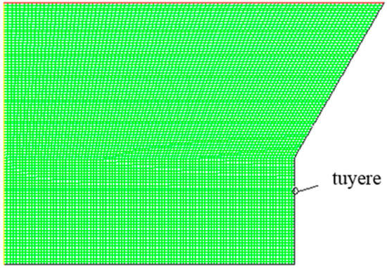
Figure 1.
Schematic diagram of the computational domain for the tuyere zone.
In the simulation, a no-slip condition is applied to walls. The pressure–velocity decoupling is done with the PISO algorithm. The tuyere zone is the velocity inlet. An explicit scheme is used to describe the shape of the interface. The time step is 0.001 s. The numerical solution is considered to be convergent when the residual errors of the variables are less than 10−5. The main parameters used in the model are shown in Table 1.

Table 1.
Parameters used in this model.
The unsteady simulation initialization conditions are shown in Figure 2. The lower part is the coke layer, and the porosity is 0.4; the upper part is gas.
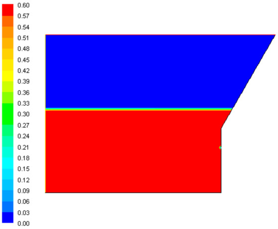
Figure 2.
Initialization condition of the coke volume fraction in the model.
3. Results
3.1. Unsteady Simulation of the Raceway Formation Process
Taking the typical COREX melter–gasifier nozzle injection operation parameters as an example, the gas velocity is set to 200 m/s; the spray inclination angle is 4°, and the parameters of the shape of the raceway zone and the volume fraction of the gas–solid particles at different times are tracked. The gas volume fraction at different time periods is shown in Figure 3.
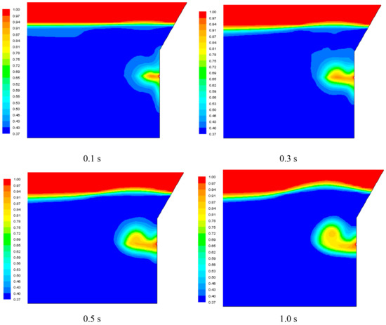
Figure 3.
Variation of gas phase volume fraction with time.
It can be seen from Figure 3 that the volume fraction of the gas phase changes significantly over time. At the beginning of the injection, the gas develops radially toward the center. Then, the gas moves straight to the center, and the upper and lower sides develop slowly. Over time, the expansion of the radial direction begins to become slow and finally stagnate, at which point the gas begins to extend upwards in the axial direction, slowly forming an arc-shaped cavity region. The upper portion of the cavity region exhibits a semicircular or semi-elliptical shape, which lasts for a long period of time. Finally, the gas forming bubble-like sphere begins to drift upward when the gas pressure in the cavity accumulates to a certain extent.
Combining the above theory, it can be determined from the change of the gas phase volume fraction, and from the start of the injection to the formation of the raceway zone, that the gas first develops in the radial direction and reaches a certain degree before starting to develop upward. The reason for this development is that the porosity of the coke bed is continuously reduced under the compression of the gas; the gap between the coke particles becomes increasingly smaller, and the resistance of the gas to the depth development is increased. When compressed to a certain limit (simulated by setting the coke porosity limit to 0.37), the resistance of the gas in the radial direction is so large that the gas cannot expand forward, and the gas grows upwards.
Figure 4 shows the depth variation of the radial development of the gas over time. It can be seen from the figure that, as the blowing time changes, the depth of the raceway zone first increases rapidly, and after 0.4 s, it begins to stabilize and finally reaches a maximum of about 800 mm.
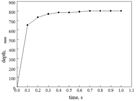
Figure 4.
Variation of raceway depth with blowing time.
Figure 5 shows the raceway behaviour in our previous experimental study [26]. The result indicates that particles rotate in front of the tuyere, and a stable cavity can be observed. Comparing the present numerical simulation and the previous physical simulation, the calculation result is consistent with the results of the physical experiment. The shape of the raceway shows similar features. These agreements verify the applicability of the present model for investigating the characteristics of the raceway in a melter gasifier under different conditions.
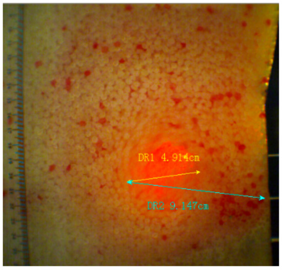
Figure 5.
Raceway behaviour in the experiment.
3.2. Effect of the Velocity of the Blowing Gas on the Cavity Size of the Raceway
According to the previous analysis, the shape and boundary of the raceway zone are generally stable from the time when the depth reaches the maximum and the time when the air mass begins to drift away from the raceway zone. On this basis, the effects of the different gas kinetic energies of blasting (i.e., airflow velocity) on the shape and size of the raceway zone are considered. Figure 6 shows the volume fraction diagram of the gas phase when the injection angle is four degrees and the gas velocities are 150 m/s, 200 m/s, 250 m/s, and 300 m/s, respectively.
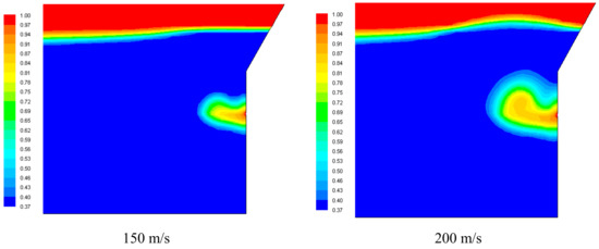
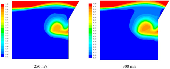
Figure 6.
Gas phase volume fraction fractions at different blowing velocities.
Combined with the velocity cloud map and the gas phase volume fraction map, it can be seen that the greater the gas injection speed, the deeper the depth of the raceway, and the larger the cavity volume when it is stabilized, which can also be seen from its depth and height. Figure 7 shows the depth variation of the raceway under different gas velocity conditions.
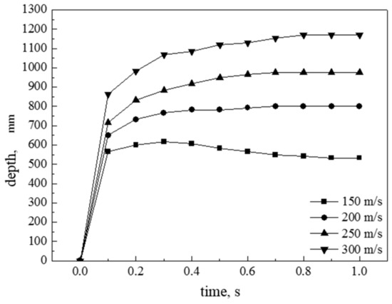
Figure 7.
Variation of raceway depth with time at different blowing velocities.
Under different gas velocities, the penetration depth is different. With an increase in gas velocity, the depth of the coke layer, through which the gas flows, increases. As can be seen from Figure 7, the cavity depth changes in the four blowing situations are basically the same—that is, both increase from the beginning and finally stabilize. The variation of the depth of the raceway also directly reflects the variation of the volume of the cavity in the raceway. When the raceway zone is stable at 150 m/s, the depth is about 500 mm, at 200 m/s, the depth is about 800 mm, at 250 m/s, the depth is about 950 mm, and at 300 m/s, the depth is about 1200 mm.
The depth and height values of the raceway zone in the stable period at each blowing speed are plotted, as shown in Figure 8. This makes it easier to visually observe how the two change with the injection speed. The main reason for this trend is that the velocity of the blowing gas increases—that is, the kinetic energy of the blast increases, the amount of gas injected per unit time increases, the gas pressure in the cavity increases, and the ability to compress the coke particles also increases. When the gas pressure and the coke layer resistance are balanced, the cavity volume is also large.
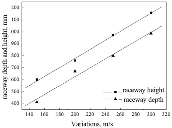
Figure 8.
Variations of raceway depth and height with blowing velocity.
4. Conclusions
The formation process of the tuyere of the COREX melter–gasifier was simulated by Euler gas–solid two-phase flow theory. The shape and size of the relatively stable period of the raceway were obtained. The influence of the jet velocity on the depth and height of the raceway is analyzed. The main results are as follows.
- (1)
- As the gas continues to inject, the cavity first grows deep into the furnace. After reaching a certain depth, the cavity begins to develop upwards, and the cavity volume increases. The time taken from the start of the gas to the formation of the stable raceway shape is short, and then the depth and height of the raceway and the volume of the cavity are stable for a long period of time.
- (2)
- Under the condition that the normal blowing speed of the COREX melter–gasifier is 250 m/s and the blowing angle is 4°, the depth of the raceway is about 950 mm, and the shape of the raceway is approximately semi-elliptical.
- (3)
- As the velocity of the tuyere gas injection increases, the depth and height of the raceway increase, and the volume of the cavity in the raceway zone increases as it stabilizes, but the shape of the raceway does not change significantly.
Author Contributions
Conceptualization, Y.S. and R.C.; methodology, Y.S. and Z.Z.; software, G.W. and Y.S.; formal analysis, H.Z. and Y.L.; investigation, X.L. and Y.H.; writing, Y.S. and R.C.; supervision, G.W. and L.L.; funding acquisition, Y.S. and R.C.
Funding
This research was funded by the Natural Science Foundation of Liaoning Province (No.20170540476), Liaoning Province Doctor Startup Fund (No.20170520079). Also, special thanks to the project, which is sponsored by the ‘Liaoning BaiQianWan Talents Program’.
Conflicts of Interest
The authors declare no conflict of interest.
References
- Anameric, B.; Kawatra, S.K. Direct iron smelting reduction processes. Miner. Process. Extr. Metall. Rev. 2008, 30, 1–51. [Google Scholar] [CrossRef]
- Qu, Y.X.; Zou, Z.S.; Xiao, Y.P. A Comprehensive Static Model for COREX Process. ISIJ Int. 2012, 52, 2186–2193. [Google Scholar] [CrossRef]
- Zhou, H.; Wu, S.L.; Kou, M.Y.; Luo, Z.G.; He, W.; Zou, Z.S.; Shen, Y.S. Discrete Particle Simulation of Solid Flow in a Large-Scale Reduction Shaft Furnace with Center Gas Supply Device. ISIJ Int. 2018, 58, 422–430. [Google Scholar] [CrossRef]
- Kumar, P.P.; Gupta, P.K.; Ranjan, M. Operating experiences with Corex and blast furnace at JSW Steel Ltd. Ironmak. Steelmak. 2008, 35, 260–263. [Google Scholar] [CrossRef]
- Zhou, H.; Wu, S.L.; Kou, M.Y.; Yao, S.; Shen, Y.S. Analysis of Coke Oven Gas Injection from Dome in COREX Melter Gasifier for Adjusting Dome Temperature. Metals 2018, 8, 921. [Google Scholar] [CrossRef]
- Di, Z.X.; Luo, Z.G.; Zou, Z.S. Fractal study on raceway boundary. J. Iron Steel Res. Int. 2011, 18, 16–19. [Google Scholar] [CrossRef]
- Gupta, G.S.; Rudolph, V. Comparison of blast furnace raceway size with theory. ISIJ Int. 2006, 46, 195–201. [Google Scholar] [CrossRef]
- Hatano, M.; Fukuda, M.; Takeuchi, M. An experimental study of the formation of raceway using a cold model. Tetsu Hagane 1976, 1, 25–32. [Google Scholar] [CrossRef]
- Sastry, G.K.; Gupta, G.S.; Lahiri, A.K. Void formation and breaking in a packed bed. ISIJ Int. 2003, 43, 153–160. [Google Scholar] [CrossRef]
- Rajneesh, S.; Sarkar, S.; Gupta, G.S. Prediction of raceway size in blast furnace from two dimensional experimental correlations. ISIJ Int. 2004, 44, 1298–1307. [Google Scholar] [CrossRef]
- Hiroshi, T.; Nobuyuki, K. Cold model study on burden behaviour in the lower part of blast furnace. ISIJ Int. 1993, 33, 655–663. [Google Scholar]
- Zhou, D.D.; Cheng, S.S.; Zhang, R.X.; Li, Y.; Chen, T. Uniformity and Activity of Blast Furnace Hearth by Monitoring Flame Temperature of Raceway Zone. ISIJ Int. 2017, 57, 1509–1516. [Google Scholar] [CrossRef]
- Li, Y.; Cheng, S.S.; Zhang, R.X.; Chen, T. Reconstruction of Three-dimensional Temperature Distribution with Radiative Image by Monte Carlo Method in Blast Furnace Raceway. ISIJ Int. 2017, 57, 2141–2147. [Google Scholar] [CrossRef]
- Zhou, D.D.; Cheng, S.S. Measurement study of the PCI process on the temperature distribution in raceway zone of blast furnace by using digital imaging techniques. Energy 2019, 174, 814–822. [Google Scholar] [CrossRef]
- Sarkar, S.; Gupta, G.S.; Kitamura, S.Y. Prediction of Raceway Shape and Size. ISIJ Int. 2007, 47, 1738–1744. [Google Scholar] [CrossRef][Green Version]
- Frank, H.D.; Tian, F.G.; Chen, N.W. A comprehensive simulation of the raceway formation and combustions. AISTech 2009 Proc. 2009, 1, 333–344. [Google Scholar]
- Du, S.W.; Chen, W.H. Numerical prediction and practical improvement of pulverized coal combustion in blast furnace. Int. Commun. Heat Mass Transf. 2006, 33, 327–334. [Google Scholar] [CrossRef]
- Gu, M.Y.; Zhang, M.C.; Selvarasu, N.C. Numerical analysis of pulverized coal combustion inside tuyere and raceway. Steel Res. Int. 2008, 79, 17–24. [Google Scholar] [CrossRef]
- Shen, Y.S.; Shiozawa, T.; Austin, P.; Yu, A.B. Modelling of injecting a ternary coal blend into a model ironmaking blast furnace. Miner. Eng. 2016, 90, 89–95. [Google Scholar] [CrossRef]
- Shen, Y.S.; Yu, A.B. Model study of the effect of bird’s nest on transport phenomena in the raceway of an ironmaking blast furnace. Miner. Eng. 2014, 63, 91–99. [Google Scholar] [CrossRef]
- Hou, Q.F.; E, D.Y.; Yu, A.B. Discrete Particle Modeling of Lateral Jets into a Packed Bed and Micromechanical Analysis of the Stability of Raceways. AIChE 2016, 62, 4240–4250. [Google Scholar] [CrossRef]
- Hilton, J.E.; Cleary, P.W. Raceway formation in laterally gas-driven particle beds. Chem. Eng. Sci. 2012, 80, 306–316. [Google Scholar] [CrossRef]
- Wei, G.C.; Zhang, H.; An, X.Z.; Xiong, B.; Jiang, S.Q. CFD-DEM study on heat transfer characteristics and microstructure of the blast furnace raceway with ellipsoidal particles. Powder Technol. 2019, 346, 350–362. [Google Scholar] [CrossRef]
- Sun, J.J.; Luo, Z.G.; Di, Z.X.; Zhang, T.; Zhou, H.; Zou, Z.S. Definition of Raceway Boundary Using Fractal Theory. J. Iron Steel Res. Int. 2015, 22, 36–41. [Google Scholar] [CrossRef]
- Sun, J.J.; Luo, Z.G.; Zou, Z.S. Numerical simulation of raceway phenomena in a COREX melter gasifier. Powder Technol. 2015, 281, 159–166. [Google Scholar] [CrossRef]
- Sun, Y.; Luo, Z.G.; Zou, Z.S.; Liu, H.H. Determining raceway boundary by image processing via high-speed video camera. J. Northeast. Univ. (Nat. Sci.) 2009, 30, 1458–1461. [Google Scholar]
© 2019 by the authors. Licensee MDPI, Basel, Switzerland. This article is an open access article distributed under the terms and conditions of the Creative Commons Attribution (CC BY) license (http://creativecommons.org/licenses/by/4.0/).