Article

The Minimum Safe Thickness and Catastrophe Process for Water Inrush of a Karst Tunnel Face with Multi Fractures

1
School of Civil Engineering, Henan Polytechnic University, Jiaozuo 454000, China
2
School of Highway, Chang’an University, Xi’an 710064, China
3
State Key Laboratory for Geomechanics and Deep Underground Engineering, China University of Mining & Technology, Xuzhou 221116, China
*
Author to whom correspondence should be addressed.
Processes 2019, 7(10), 686; https://doi.org/10.3390/pr7100686
Submission received: 29 August 2019 / Revised: 18 September 2019 / Accepted: 20 September 2019 / Published: 2 October 2019

Abstract

:
Water inrush of tunnel face is one of the most common geological disasters during tunnel construction in China. Aiming at the rock mass with multi fractures in water-resistant strata ahead of karst tunnel, the compressive-shear cracking property is analyzed by fracture mechanics theory and the change law of rock bridge shear strength with branch crack propagated length under karst water pressure and geo-stress is studied according to Mohr-Coulomb strength criterion. Moreover, the critical water pressure of water-resistant strata with multi fractures under tension-shear failure is deduced. The safe thickness of water-resistant strata with multi fractures ahead of karst tunnel is established based on two band theory and critical water pressure, and the influence of karst water pressure, initial crack length, crack spacing, array pitch of cracks, lateral pressure coefficient and the angle between the crack and the maximum principal stress on the minimum safe thickness of water-resistant strata are discussed. A 3 Dimension Distinct Element Code (3DEC) considering the fluid-solid coupling effect and structural characteristics of rock mass is adopted to study the catastrophe process and the influence of karst cavity scale on displacement and seepage field in water-resistant rock mass ahead of tunnel in the process of sequential excavation. The numerical simulation results show that: The transition from the single effect of unloading on the extrusion displacement of karst tunnel face to combined action of unloading and karst water pressure occurs with the tunnel face advance; The displacement at each measuring point in water-resistant strata continues to increase in the process of tunnel excavation; The extrusion displacement and water flow velocity in tunnel face suddenly increase when the water inrush pathway is about to form; With the increase of karst cavity size, the minimum thickness of water-resistant strata, the displacement of measuring point and pore pressure of crack increase. The study results provide a reference for early warning and prevention of water inrush in karst tunnel face.

Graphical Abstract

1. Introduction

With the “Belt and Road Strategy” moving forward constantly, more and more tunnel engineering with the characteristics of deeply buried depth, long distance, strong karst, high geo-stress, high water pressure, and complexes logical structure will be built in the western karst region of China. Unfavorably, many kinds of geological disasters often occur in the course of tunnel construction due to the influence of karst development degree, the position relationship between the karst structure and the tunnel, karstic fillings and the disturbance of tunnel excavation. Water and mud inrush are the most common and dangerous problems that tunnel constructors encountered. Under the existed detection technology, the probability of water inrush from the lateral wall of tunnel is small, and the main form of water inrush is the karst tunnel face mode. Water inrush not only affects the construction safety of tunnel engineering, but also endangers human lives and property. Therefore, it is necessary to study the minimum safe thickness and water inrush catastrophe process of water-resistant strata for the design and construction of karst tunnels.
In karst environment, various karst geomorphic units in the strata, such as matrix, funnels, underground rivers, shafts, ducts, caves and vertical fractures connected to them, are interrelated and hydraulically connected, forming a large karst groundwater network. Therefore, the strata conceptual model including the above karst geomorphic units is large-scale in size and continuous with holes (as shown in Figure 1a). If the whole karst environment is taken into account in the study of water inrush catastrophe of karst tunnel face (especially through theoretical analysis and numerical simulation), it is difficult to implement because of the unpredictability of karst form and the huge amount of calculation. Generally, when the study is under engineering scale, only the certain-ranged surrounding rock mass which is affected by tunnel excavation is taken as the research object (as shown in Figure 1b), and the karst structures outside the affected area are regarded as the boundary condition, which can meet the requirements under the engineering scale enough. Recent years, a great number of scholars carried out researches on the minimum safe thickness of water-resistant strata and many achievements have been acquired. Fraldi and Guarracino [1,2] established formulas to analyze the collapse mechanisms in tunnel roof based on Hoek–Brown failure criterion and calculus of variations. Yang [3] established the expression of the minimum thickness for rock plug based on upper bound theorem in combination with variation principle. Guo [4] calculated the critical thickness between tunnel and concealed cavity based on the schwarz alternating method and Griffith strength criterion, and analyzed each factor’s influence on the minimum safe distance. Xu [5] investigated the minimum safety thickness of the rock resisting water inrush from filling-type karst caves by adopting the theory of elastic mechanics, and analyzed the influence of the depth-span ratio of the filling-type karst cave, shear strength indexes of the filling materials, and the depth of the tunnel on the minimum safety thickness. However, the karst water pressure is regarded as stationary load applied to the water-resistant strata and the water-rock interaction is neglected, so the above mechanical model is limited to the intact water-resistant strata. Gan [6] proposed a reasonable range of safety thickness of rock wall which could consider blasting disturbance, ground stress and the extension of water-bearing fractured. Li [7] put forward the concept of minimum safety waterproof thickness and given the expression of semi-analytical solution based on fracture mechanics and plastoelasticity. Guo [8] believed that the water inrush occurs in the vicinity of the tunnel face due to decreasing of the critical water pressure of fracture which is caused by excavation and disturbance, and established the calculating formula of the safe thickness of rock wall with joints on the basis of the critical water pressure. Previous researches on the minimum safe thickness of water-resistant strata only consider the influence of single-fracture, while the interaction between fractures is ignored. However, the rock mass surrounding karst cavity usually has a large number of fractures, and the interaction between cracks may inhibit or enhance the fracture behavior. So, it should not be disregarded in the study of the fracture features and the damage evolution for rock cracks.
Cognizing the catastrophe process of water inrush is the basis for establishing the minimum safe thickness for water inrush of water-resistant strata, and it is also the theoretical basis for the prevention and control of water inrush geological disasters. There are much more achievements have been obtained about this theme. Wu [9] performed numerical simulation on the case of underground water inrush from fracture section to the coal mine floor, and analyzed the mechanism of water inrush. Li [10] studied the impacts of a number of factors such as tunnel depth, the surrounding rock grade, the size of the karst cave, the distance between the tunnel and the karst cave and the depth–span ratio of the karst cave, on the stability of surrounding rock in tunnels. Wang [11] studied the deformation and failure characteristics of the water-resistant strata in the process of tunnel construction under different cavity scale and karst water pressure. Anna [12] used Three-dimensional (3D) Finite Element Method (FEM) models to determine and quantify the global stability of excavations. Jiang [13] simulated the current and future scenarios of roadway gushing at the bottom of the coal mine use by finite element numerical flow model. Parise and Lollino [14] explored the progression of instability of karst caves by numerical analyses, also analyzing and modeling factors leading to underground failures. Geng [15] used the Particle Flow Code (PFC) to simulate the whole process of mud and water burst caused by tunneling in water-rich fault zones with different dip angels and revealed the influence of fault dip angles on mud and water bursts. In the abovementioned studies, the water-resistant strata ahead of karst tunnel face is basically regarded as porous continuous medium, and the rock mass of water-resistant strata has no cracks or only includes a single crack.
This study aims to provide theoretical support for early warning and prevention for water inrush of a karst tunnel face. As to the water-resistant rock mass with multi fractures ahead of a karst tunnel face, the compressive shear cracking property of multi fractures and the propagation and coalescence law of the branch crack of multi fractures are analyzed under karst water pressure and geo-stress from the perspective of fracture mechanics and Mohr-Coulomb strength criterion. Then, the analytical models to determine the critical water pressure and the minimum safety thickness of water-resistant strata with multi fractures are proposed, and meanwhile, parametric study of the minimum safe thickness are carried out. Finally, the numerical model for water-resistant strata with multi fractures ahead of karst tunnel face are established by 3DEC and the method of setting virtual joints to study the catastrophe process for water inrush in karst tunnel face and the influence of karst cavity size on seepage field and displacement field of water-resistant strata in water inrush process.

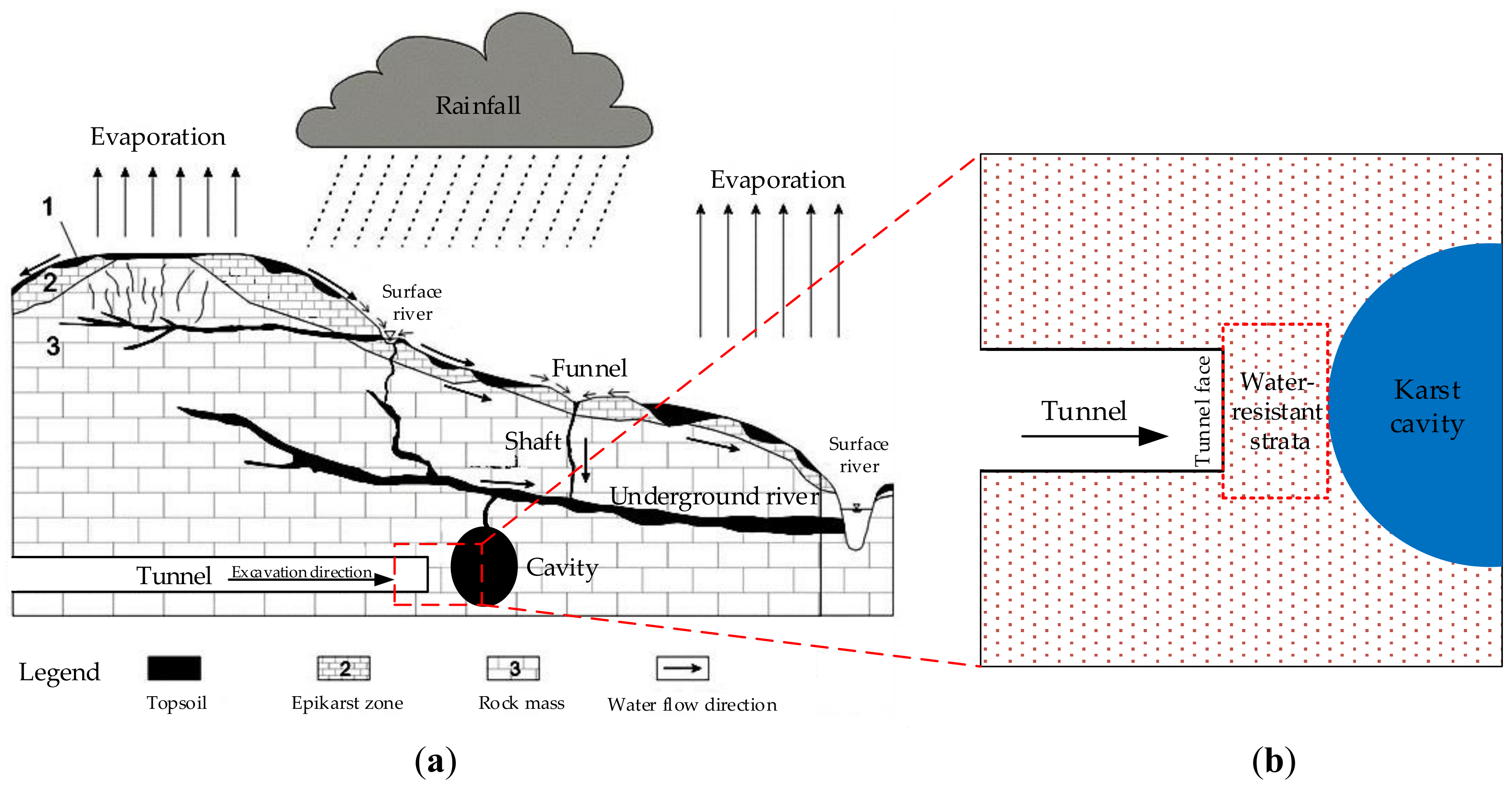
2. Structure of Water-Resistant Strata and Its Hydraulic Failure Mode

The water-resistant strata, the final barrier that prevents karst water from entering the tunnel face, refers to the rock mass between the tunnel face and the karst cavity with high pressure and rich water [7]. However, there are many cracks and joints with various scales in engineering rock mass that changed its stress state and weakened its mechanical properties. Therefore, the influence of cracks must be taken into account in the process of establishing the minimum safe thickness formula of water-resistant strata with multi fractures. The cracks can be divided into cross-persistent joints and non-persistent joints according to the development degree of crack. The survey of rock mass shows that the cross-persistent joints only account for a small part of total joints and a lot of joints are non-persistent joints in natural [16]. In addition, to avoid the effect of large-scale cross-persistent joints, many underground constructions are constructed in the surrounding rock mass with better quality as soon as possible. Duo to the above two causes, most of the cracks that play an important role in underground engineering are non-persistent joints, and the rock mass with non-persistent joints is a common type in underground engineering [8]. Therefore, it has great significance to study the water inrush mechanism of water-resistant strata with multi cracks.

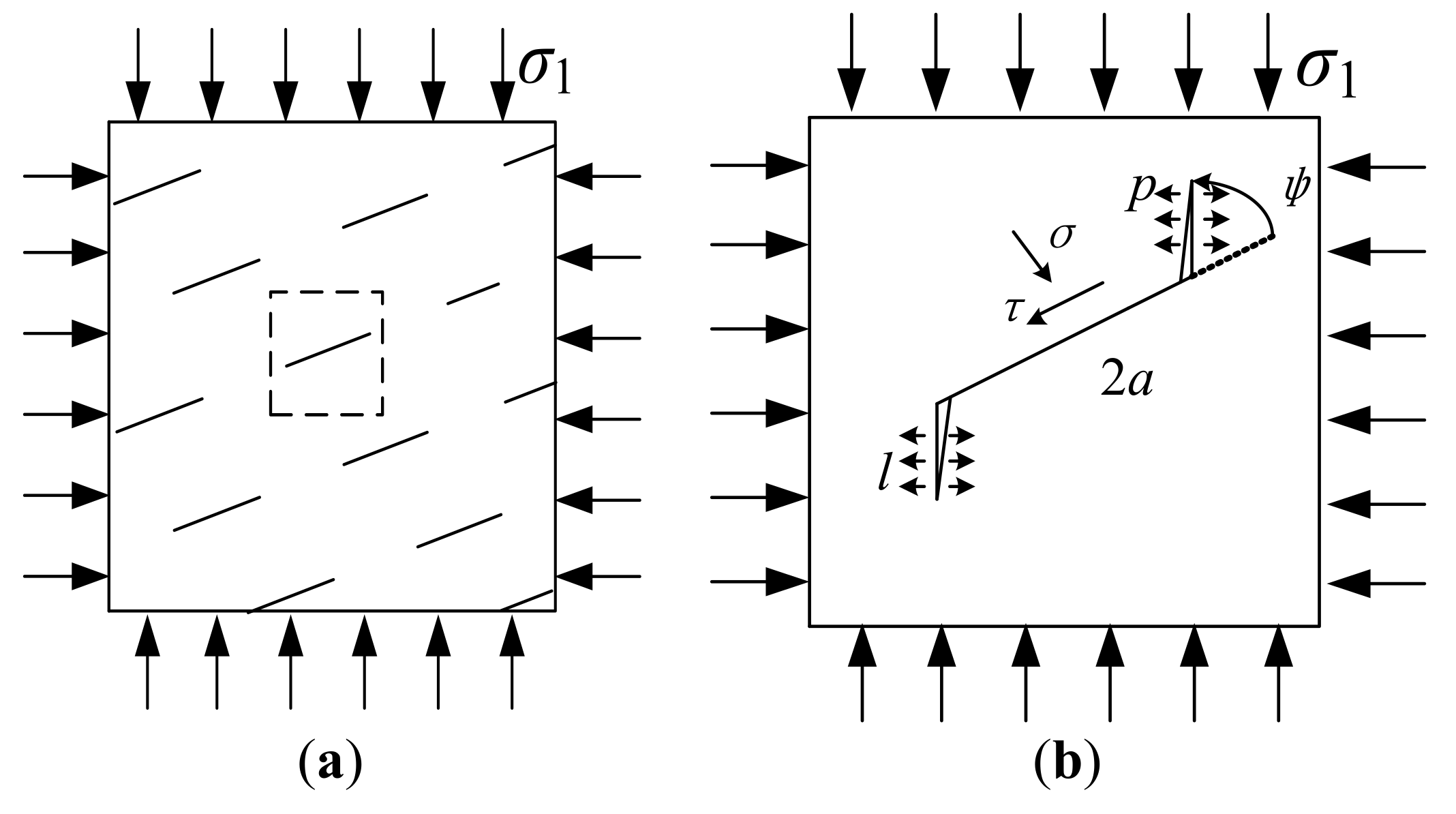
2.1. Failure Mechanics Mode of Fracture with High Water Pressure

There are lots of non-persistent joints in water-resistant strata. As frictional force is overcome by shear stress induced by far-field stress, the crack surface would slide over each other, causing stress concentration on the tip of the crack and leading to the initiation and splitting propagation of wing crack [17,18]. Then the wing crack propagated under the coupling of engineering excavation disturbance and high pore fluid pressure until the rock bridge between wing cracks is cut off by the shear stress. Finally, the water inrush pathway is formed in the water-resistant strata due to the transfixion of rock bridge. The type of water inrush of water-resistant strata with multi fractures is usually high hydraulic fracturing [7], and its mechanical mechanism can be analyzed by fracture mechanics. For example: Distance kilometer(DK)124+602 of Yesanguan Tunnel, Kilometer(K)29+543 of Wuzhishan Tunnel, DK354+879 and DK361+764 of Yuanliangshan Tunnel, the cause of water inrush in these accidents is hydraulic fracturing. From the perspective of fracture mechanics, hydraulic fracturing of fractured rock mass has two main modes: tensile-shear failure and compressive-shear failure. The main distinction of them is the difference of normal stress state on the crack surface. The critical water pressure for compression-shear failure of cracks in rock mass at different depths is much lower than that for tension-shear failure (see Figure 2), and the critical water pressure for compression-shear failure is easier to occur [8]. Due to the stratum bulk density is bigger than that of the groundwater, the normal stress of crack surface containing water in the surrounding rock of underground engineering does not appear tensile stress under the condition of non-artificially fracture in the environment of in-situ stress and groundwater pressure. So, the model of hydraulic fracturing is compression shear failure under the natural condition.
It is difficult to analyze the generation mechanism of cracks because the cracks are randomly distributed in three-dimensional space. For convenience, a simplified two-dimensional plane crack with the character of closed and orderly is studied (see Figure 3a). Based on fracture mechanics, a mechanical model as shown in Figure 3b is established to explore the generation and propagation mechanism of multi cracks in rock mass. The fractured rock mass is under far field stress σ1 and σ3. The angle between the crack and the vertical stress σ1 is ψ, and the initial crack’s length is 2a. The pore water pressure is p in the crack and the water pressure is equal in each direction along the crack. The stress state on the crack surface (the compressive stress is positive) can be expressed as:
{ σ n = σ 1 + σ 3 2 σ 1 σ 3 2 cos 2 ψ p τ n = σ 1 σ 3 2 sin 2 ψ
According to the maximum circumferential stress criterion, the initial crack extends along the maximum normal stress direction. The cracking angle is 70.5°. The stress intensity factor at the crack tip is obtained considering the effect of water pressure [19].
K I   = 2 3 τ e f f π a = 2 3 ( τ n σ n f ) π a
when KI > KIC (the value of fracture toughness for type I), wing crack initiates then propagates at the tip of the initial crack. According to the fracture failure test of rock-like materials with multi-cracks [20,21], it is found that the gradual damage process of cracks generally has three forms: (1) The axial transfixion failure, (2) the tension-shear combined fracture failure, and (3) the wing crack shear connection failure. Bobet [22] found that the mode of coalescence for cracks is usually the tension-shear in biaxial compression through rock model material test. So this paper discusses the tension-shear combined fracture failure of multi fractures rock mass under the combined effect of far-field stress and high water pressure based on the rock fracture mechanics theory.

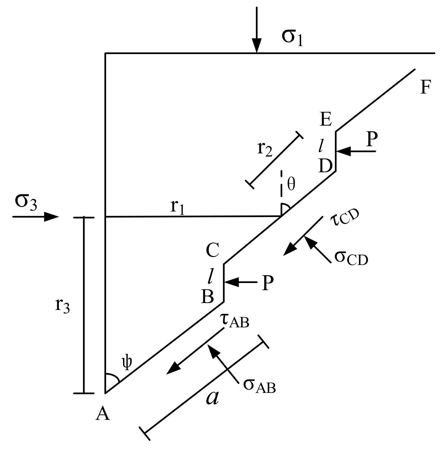
2.2. Critical Water Pressure of Hydraulic Fracturing for Rock Mass with Multi Fractures

With the wing crack generating and extending along the maximum normal stress direction under the hydraulic pressure and ground stress, the cut-resistant capacity of rock bridge is increasingly weakened until the rock bridge between the contiguous wing cracks cut off by shear stress. Consequently, the cracks are joined and interconnect, the water inrush pathway is formed and the water inrush is occurred in the water-resistant strata. Tension-shear combined failure characteristics of rock bridge is shown in Figure 4 [20].
In Figure 4, a is ½ the length of the initial crack, CD is the rock bridge, BC and DE are the wing crack. The angle between the rock bridge and the vertical stress σ1 is θ, σCD and τCD are the normal stress and shear stress of rock bridge.
Analyzing the cell body shown in Figure 4, we can obtain the mechanics balance as [23]
{ σ 3 r 3 a ( τ n e sin ψ + σ n e cos ψ ) r 2 ( t C D sin θ + σ n C D cos θ ) p l = 0 σ 1 r 1 + a ( τ n e cos ψ σ n e sin ψ ) + r 2 ( t C D cos θ σ n C D sin θ ) = 0
where
{ r 1 = a sin ψ + d 2 + h 2 2 sin ψ arctan d / h ) = a sin ψ + r 2 sin θ = a sin ψ + c 1 r 2 = d 2 + h 2 2 sin ( ψ arctan d h ) / sin θ = c 1 / sin θ r 3 = a cos ψ + r 2 cos θ + l = a cos ψ + d 2 + h 2 2 cos ( ψ arctan d / h ) = a cos ψ + c 3 tan θ = d 2 + h 2 2 sin ( ψ arctan d / h ) d 2 + h 2 2 cos ( ψ arctan d / h ) l = c 1 c 3 l
According to upper formula, we can obtain:
{ σ n C D = A cos θ B sin θ r 2 τ C D = A sin θ B cos θ r 2
According to Mohr–Coulomb strength criterion, we can know that:
τ = f σ n C D + c
when
{ τ C D > τ ,   Failure τ C D = τ ,   Critical   state τ C D < τ ,   Safety
It is assumed that the crack length 2a of multi fractured rock is 1.5 m, the density of rock mass is 2.70 g/cm3, the buried depth of tunnel is 500 m, the array pitch of crack is 0.5 m, the crack spacing is 0.75 m, the rock cohesion is 0.85 MPa, the angle between the crack and the maximum principal stress ψ is 60°. According to Equations (5) and (6), we can know the change regulation of shear stress and shear strength of rock bridge with branch crack propagation length under different pressure. The results are shown in Figure 5.
From Figure 5, when the water pressure p is constant, with the increase of the crack propagation length, the shear stress of rock bridge increases and its growth rate also increases, and the cut-resistant capacity increases firstly and then decreases. Take p = 1 MPa for example, in the initial stage of branch crack propagation (l = 0.4 m), τCD = 4.87 MPa << τ = 27.6 MPa. When the branch crack propagation length is 0.58 m, τCD = τ = 32.11 MPa, the branch crack length reaches the critical length and the rock mass is in the critical state of water inrush. With the further extension of branch cracks, when τCD > τ, the rock bridge is cut off by shear stress. The higher the crack water pressure, the smaller the branch crack length when the rock bridge is cut off (p = 0.5 MPa, l = 0.58 m, p = 1 MPa, l = 0.578 m, p = 2 MPa, l = 0.576 m).
When the length of rock bridge meets the shear failure condition, the corresponding hydraulic pressure is the critical water pressure. Putting Equations (4) and (5) into Equation (6), the following is obtained:
A sin θ B cos θ = c r 2 + A f cos θ B f sin θ
By simplifying Equation (8), the critical water pressure is obtained as follows:
p = A ( sin θ f cos θ ) B ( cos θ + sin θ ) c r 2 l sin θ l f cos θ
where
{ A = A p l = σ 3 r 3 a ( τ n e sin ψ + σ n e cos ψ ) p l B = σ 1 r 1 + a ( τ n e cos ψ σ n e sin ψ )
By combining Equations (4) and (8), the wing crack length l caused by initial crack under water pressure and stress is [23]:
t a n θ = c 1 c 3 l = A B tan θ + ( B tan θ A ) 2 4 c ( c 3 l ) [ B + A tan θ + c ( c 3 l ) ] 2 c ( c 3 l ) l = A 1 A 1 2 4 ( c + p tan θ ) A 2 2 ( c + p tan θ )
where
{ A 1 = A tan ϕ + B + 2 c c 3 p c 3 tan ϕ + p c 1 A 2 = c ( c 1 2 + c 3 2 ) + ( A c 3 + B c 1 ) tan ϕ A c 1 + B c 3

3. Safety Thickness of Water-Resistant Strata with Multi Fractures

3.1. Two Band Theory

The above research studied the failure mechanics mode of fracture with high water pressure and the tension-shear combined failure characteristics of rock bridge in non-persisted jointed rock mass under compression shear hydraulic fracturing. According to the research and the results of the existing literature [24,25], the water inrush mechanism of water-resistant strata with multi fractures ahead of karst tunnel can be attributed to the following two reasons: (1) Under the effect of hydraulic and chemical during the development of high-pressure water-rich karst in front of the tunnel face, the karst initial fissure zone formed with lots of fractures forms in the surrounding rock of karst cavity. It is easy to form water burst pathway and it also has no resistance capacity for high hydraulic pressure due to its strong permeability. (2) Under the combined effect of excavation unloading and high hydraulic pressure, the stress state is changed in the rock mass between tunnel face and karst initial fissure zone and its internal crack surface. This change reduces the friction coefficient of the crack surface and the critical water pressure of hydraulic fracturing, and it also results the crack expanded and interpenetrated with each other, which lead to the formation of water inrush pathway and occurrence of water inrush. There is a critical distance between the karst tunnel construction face and the karst cavity, which is defined as the minimum safety thickness of the water-resistant strata ahead of karst tunnel face.
Li [26] divided the minimum safety water-resistant strata thickness into relaxation area of surrounding rock caused by construction excavation, safe thickness and fissure zone. Guo [8] divided the safe thickness of rock wall of tunnel face into karst initial fissure zone and cracking-resistance zone. Based on the above analysis and using for reference the existing research, the minimum safety thickness of water-resistant strata between tunnel face and cavity filled with high-pressurized water is divided into karst initial fissure zone and karst hydraulic fracturing zone, as shown in Figure 6.
(1)
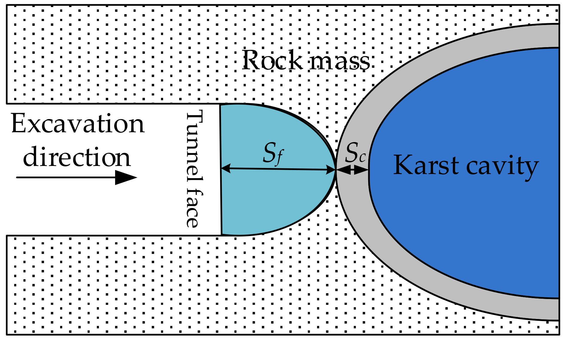
Karst initial fissure zone—Under the coupling effect of stress, chemistry, hydraulic scouring and seasonal variation of karst water pressure, the initial fracture zone caused by trenchless factors around the cavity filled water is formed. The strength of rock mass in this zone is relatively low, and the structure of rock mass is different from rock away from the cavity. At the moment, there is no mature theory to determine the range of the initial fracture zone due to the complex of formation process of the initial fracture zone around the high-pressure cavity. Now most scholars rely on field measurement or replace it with the plastic zone of the rock mass around the cavity [8,27]. In practical engineering activities, engineers often use Ground Penetrating Radar and other geophysical methods to detect the thickness of initial fracture zone and verification by drilling. According to practical engineering experience, it is generally believed that the thickness of initial fracture zone is 1~2 m [24].
(2)
Karst hydraulic fracturing zone—By substituting the far-field stress σ3 = λσ1 = λγH into the critical water pressure calculate formula (Equation (6)), we can know that:
P c = λ γ H [ ( sin θ f cos θ ) ( 2 r 3 + a B 1 ) + a B 2 ( cos θ + f sin θ ) ] 2000 [ a sin ψ ( cos θ + f sin θ ) ( a cos ψ l ) ( sin θ f cos θ ) ] γ H [ ( sin θ f cos θ ) ( 2 r 1 + a B 3 ) + a B 4 ( cos θ + f sin θ ) ] + 2000 r 2 c 2000 [ a sin ψ ( cos θ + f sin θ ) ( a cos ψ l ) ( sin θ f cos θ ) ]
According to the Equation (11), the critical water pressure is affected by the initial crack length, stress, array pitch of crack, crack spacing and the angle between crack and principal stress. In tunnel construction, the parameters (d, a, h, ψ) representing the distribution characteristics of water-resistant strata, the mechanical parameters (f) of water-resistant rock mass, and the overburden pressure (γH) are basically unchanged. However, in the process of tunnel excavation, the water-resistant strata would produce unloading phenomenon, in other words, the lateral pressure coefficient λ would decrease, which leads to the critical water pressure of water-resistant strata decrease. Therefore, it can be considered that the reason of water inrush is not caused by the increase of the karst water pressure, but caused by the decrease of the critical water pressure of hydraulic fracturing. According to the research results, the lateral pressure coefficient of water-resistant rock mass is:
λ x = λ [ 1 ( exp S x 1 . 1 R ) 1.7 ]
where Sx is the distance between any section in the hydraulic fracturing zone and the tunnel face after tunnel excavation; R is the radius or equivalent radius of the tunnel section; λx is the lateral pressure coefficient at the section of Sx in the karst hydraulic fracturing zone; At the tunnel face, S0 = 0, λ0 = 0; λ is the lateral pressure coefficient at the junction of karst initial fissure zone and karst hydraulic fracturing zone in the water-resistant strata after the unloading disturbance caused by tunnel excavation. Since the soil bulk density is greater than the groundwater bulk density, and the underground karst water surface is generally below the ground surface, the cover ground stress σ1 at the point in the formation is general greater than the karst water pressure at this point [25]; The magnitude of stress σ3 at the junction of karst hydraulic fracturing zone and karst initial fracturing zone is equivalent to karst water pressure P [28]. Therefore, the value of λ at the junction of two zones should be less than 1. Moreover, the lateral pressure coefficient changes from 0 to λ as shown in Equation (14).
When the distance between the tunnel face and the boundary of the initial fracture zone is Sx and the water pressure Pc on the crack surface is equal to critical water pressure Pw, the hydraulic fracturing will occur in the water-resistant strata with multi fractures. At this time, the distance Sx between the tunnel face and the junction of the two zones is the thickness Sf. By combining Equations (13) and (14), the thickness of karst hydraulic fracturing zone is:
S f = 11 R 17 [ ln λ ln ( λ ( sin θ f cos θ ) ( 2 r 1 + a B 3 ) + a B 4 ( cos θ + f sin θ ) ( sin θ f cos θ ) ( 2 r 3 + a B 1 ) + a B 2 ( cos θ + f sin θ ) + 1000 ( p [ 2 ( a cos ψ l ) ( sin θ f cos θ ) a sin ψ ( cos θ + f sin θ ) ] 2 r 2 c ) γ H ( sin θ f cos θ ) ( 2 r 3 + a B 1 ) + a B 2 ( cos θ + f sin θ ) ) ]
where
B 1 = sin 2 ψ sin ψ ( 1 + cos 2 ψ ) cos ψ B 2 = sin 2 ψ cos ψ + ( 1 + cos 2 ψ ) sin ψ B 3 = sin 2 ψ sin ψ ( 1 cos 2 ψ ) cos ψ B 4 = sin 2 ψ cos ψ + ( 1 cos 2 ψ ) sin ψ

3.2. Minimum Safety Thickness of Water-Resistant Strata with Multi Fractures

When the high-pressure water-rich cavity is developed in front of the tunnel face and the tunnel excavation face is apart from cavity a certain distance, the tunnel excavation should be stopped immediately to ensure the safety of construction personnel and equipment. Engineers should adopt appropriate construction scheme to reduce the karst water pressure to decrease the risk of water inrush. In the above mentioned two band theory, the minimum safe thickness of the water-resistant strata is divided into karst initial fissure zone (Sc) and karst hydraulic fracturing zone (Sf). According to the theory, when construction of the tunnel stops, the distance between the tunnel face and the cavity refers to the minimum safe thickness of the water-resistant strata with multi fractures of karst tunnel, i.e., the sum of the thickness of the karst initial fracture zone and the thickness of the karst hydraulic fracturing zone, and it is expressed as follows:
S min = S c + S f

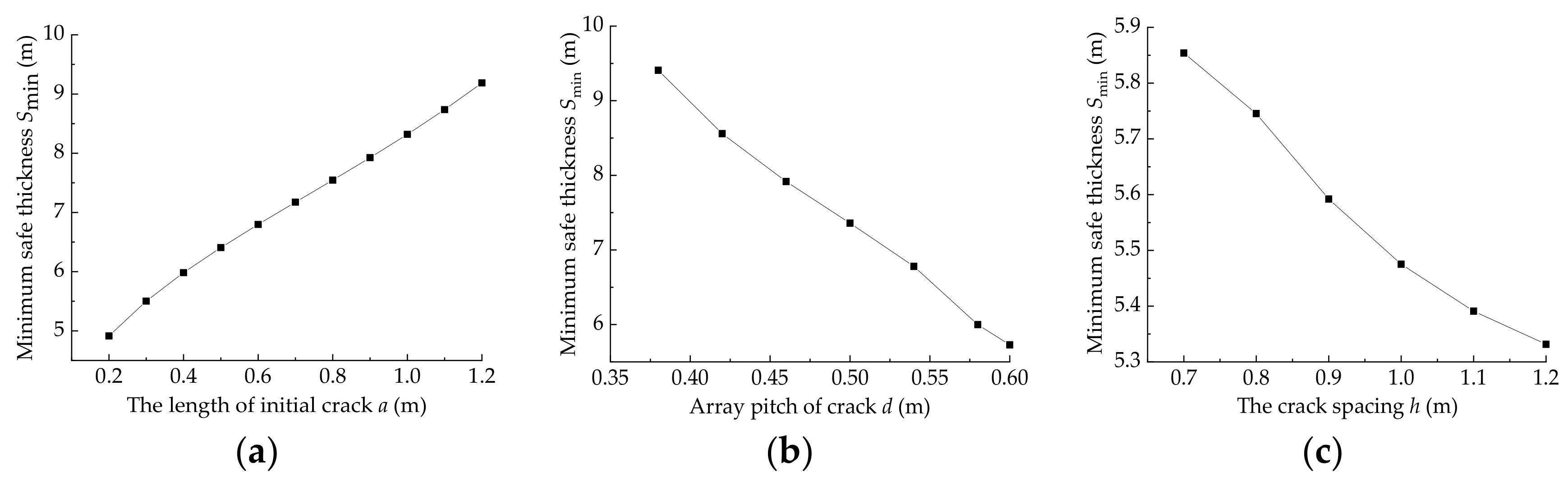
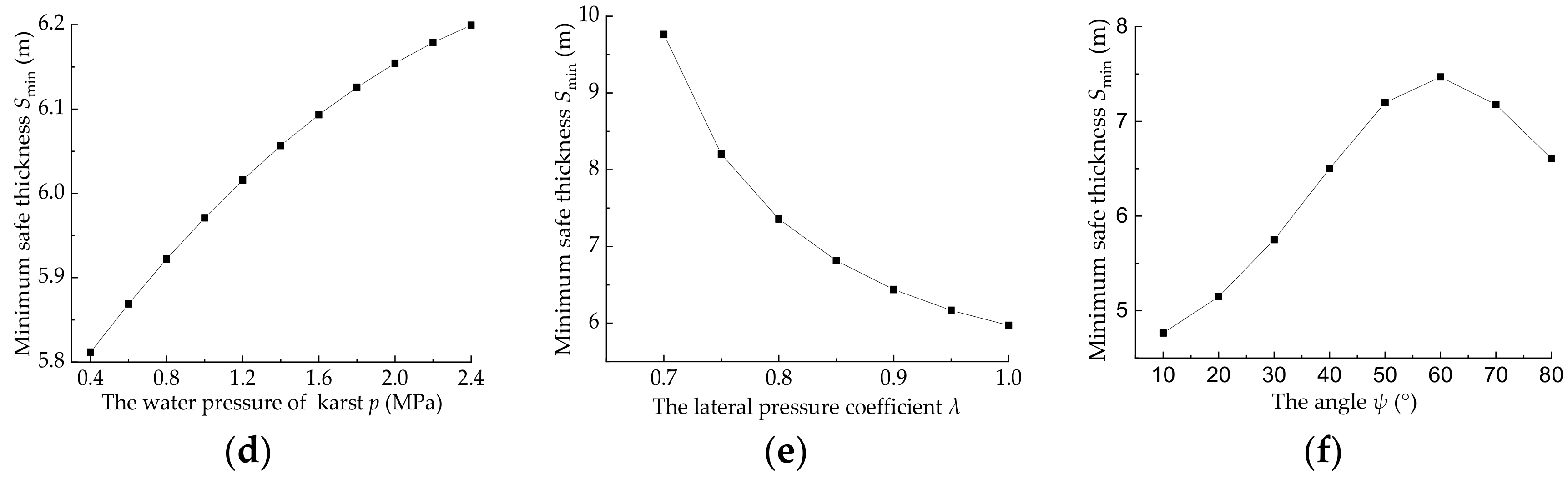
3.3. Parametric Analysis of the Minimum Safe Thickness

From Equations (15) and (17), it is obvious that the minimum safety thickness of water-resistant strata with multi fractures is related to the parameters such as karst water pressure, the distribution characteristic parameters of multi fractures and the rock mechanics parameters of water-resistant strata. According to Equation (17), it is possible to analyze the influence of various factors on the minimum safety thickness of water-resistant strata, as shown in Figure 7. When a parameter is not discussed, the parameter is determined in the minimum safe thickness calculation. The values of the parameters during the analysis are: the tunnel depth H is 500 m, the bulk density of overlying strata is 24 kN/m3, the friction coefficient f is 0.4, the initial crack length 2a is 1.6 m, the array pitch of crack d is 0.5 m, the crack spacing h is 0.75 m, the rock cohesion c is 0.85 MPa, the angle ψ between the crack and the maximum principal stress is 40°, the lateral pressure coefficient λ at the junction of the two zones is 0.8, the karst water pressure p is 1 MPa, and the thickness of the karst initial fracture zone Sc is 1.5 m.
It can be seen from Figure 7 that: (1) with the increase of initial crack length, the minimum safety thickness of water-resistant strata increases linearly. Whereas with the addition of crack array pitch and crack spacing, the minimum safety thickness of water-resistant strata decreases linearly. Moreover, the crack spacing h has less impact on the safe thickness compared to karst water pressure or crack initial length; (2) as the water pressure increases, the minimum safety thickness increase gradually. However, with the increase of the lateral pressure, the safe thickness of water-resistant strata decreases, and the descending range also decreases gradually. For instance, when λ increases from 0.7 to 0.8, the safe thickness decreases by nearly 2.5 m, but when λ increases from 0.9 to 1.0, the safe thickness only decreases 0.5 m; (3) with the increase of the angle, the safety thickness of water-resistant strata increases first and then decrease. When the angle increases from 10° to 80°, the minimum safety thickness increases from 4.76 m to 7.47 m, and then decreases to 6.61 m. The variation regulation of minimum safe thickness with the angle is the comprehensive reflection of stress state of the crack surface, the propagation length of the branch crack and shear stress of rock bridge. According to Figure 7d, the minimum safety thickness is the largest when the angle is about 60°.

4. Numerical Analysis of Water Inrush Evolutionary Process

Based on the Mohr-Coulomb strength criterion, the mechanism of the tension-shear combined fracture failure was analyzed, meanwhile the critical water pressure of hydraulic fracturing of cracks and the minimum safe thickness of water-resistant strata with multi fractures ahead of karst tunnel were established. However, the water inrush of karst tunnel is a system instability failure process under the effect of tunnel excavation. The abovementioned instability criterion can only be used to judge the terminal stage of water-resistant strata after water inrush. The water inrush of water-resistant strata with multi fractures is a highly nonlinear problem in mathematics that involves the process of crack initiation, propagation and coalescence, and it is difficult to describe the whole process of water inrush theoretically. However, the numerical simulation is an effective tool. Some scholars have carried out related research with the help of numerical calculation methods, and achieved significant advances. Olson and Taleghani [29] clarified mechanical interaction between pressurized fractures and examined the simultaneous propagation of multiple hydraulic fracture segments with a boundary element numerical model. Kan Wu and Jon E. Olson [30] proposed a novel and simplified 3D displacement discontinuity method and with it efficiently solve the problem of multiple 3D interacting fracture. M. Vahab and N. Khalili [31] presented a fully coupled hydro-mechanical model on the basis of X-FEM and studied the multizone hydraulic fracturing in saturated deformable porous media using the computational framework. However, the methods they use are too difficult or the commercial modeling capabilities of the software in their study are too poor to be applied by general researchers for carrying out studies. In view of the great difficulty of the above method, this study uses the large commercial discrete element software 3DEC as a platform, combined with the method of setting virtual joints to simulate the hydraulic fracturing process of water-resistant strata with multi fractures. In 3DEC, the rock material model is discretized into an assemblage of discrete block. The software can only analyze the displacement and rotation of each block in the model, but can’t directly track the newly generated cracks. However, we solve this problem by setting virtual joints between blocks. The virtual joint is the artificial structural boundary in the numerical model. After being artificially given a set of reasonable mechanical parameters, it is locked with the adjacent blocks and they can be regarded as a whole, ensuring the existence of virtual joints does not affect the calculation result of the model. Under the action of external force, each block undergoes different degrees of displacement and rotation with the contact between adjacent blocks constantly adjusting. If this process has brought the tensile stress (or shear stress) on the virtual joints exceeded their limiting tensile strength (or shear strength), then the two adjacent block separates from each other, meanwhile, the virtual joint between them is automatically assigned another set of mechanical parameters which are used to describe cracks and turns into a new crack with recorded by the software [32]. In this way, the evolution process of the initiation, propagation and coalescence of the new cracks can be better tracked. In this study 3DEC and the method of setting virtual joints are applied to simulate the hydraulic fracturing process of water-resistant strata with multi fractures, where the displacement field, seepage field and water pressure distribution characteristics of water-resistant strata are analyzed during sequential excavation and the influence of karst scale on water inrush of tunnel is also investigated.

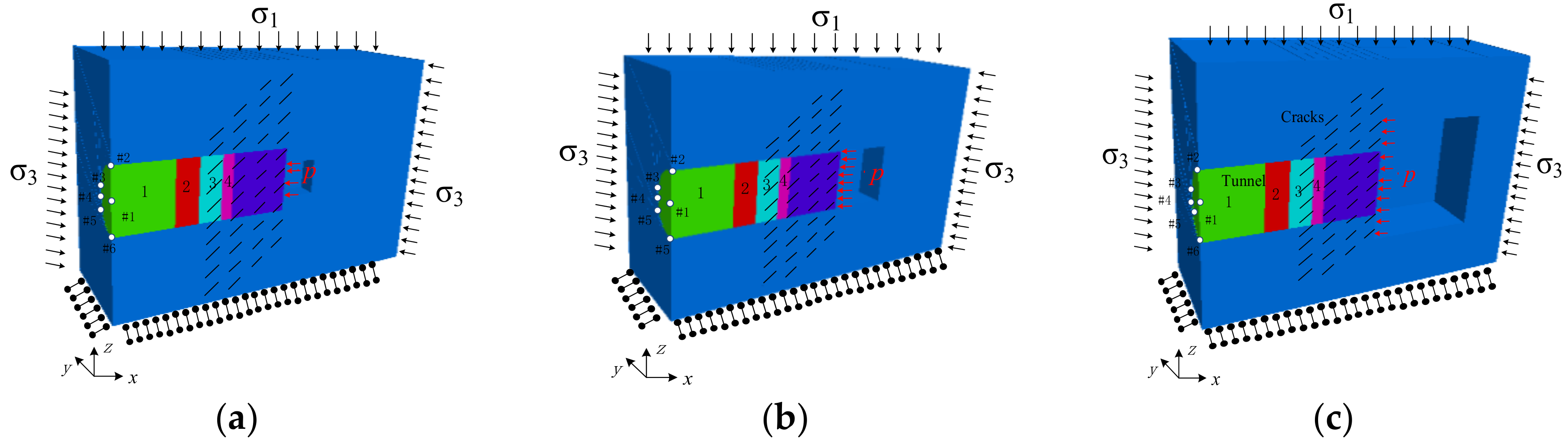
4.1. Numerical Calculation Model

A three-dimensional tunnel model is built by using the 3DEC as shown in Figure 7. According to the karst scale, the cavities are divided into large, medium and small cavity with average diameters of 20.0 m, 10.0 m and 6.0 m, respectively. The calculation model size for stability analysis of water-resistant strata is x × y × z = 90 m × 80 m × 80 m, the excavation tunnel which has a three-centered circular arch shape is situated in the middle of the model, and the radii are 4.97 m, 9.58 m and 6.3 m respectively. The buried depth of the tunnel is 400 m. The horizontal displacement constraints are imposed on the left and right boundaries (x = −30, 60 m). Axial displacement constraints are imposed on the back and front boundaries (y = ±40 m). The z = −40 m plane is a fixed constraint and σ1 = 8 MPa, σ3 = 5 MPa. The invariable karst cave hydraulic pressure is 2 MPa, this value is based on the above-mentioned calculation results of the critical water pressure and the extensive construction experience in karst tunnels. Non-persisted joints are set in the local area aside the karst cavity in the water-resistant strata. The thickness of this area should be larger than the critical safety thickness of the water-resistant strata, which not only ensures the accuracy of the calculation results, but also can fully reflect the effect of joints on the failure process of the water-resistant strata. The joints have an inclination angle of 45°and a fixed spacing of 2 m in this model. In the above theoretical analysis, we find that water inrush from the karst tunnel face is usually resulted from the tunnel excavation causing the local rock mass unloading and further reducing the critical water pressure caused by the hydraulic fracturing. Therefore, excavation steps are set up to simulate unloading behavior in numerical simulation. Each step in the numerical simulation is 10 m, 4 m, 4 m, 2 m, and 2 m respectively. When the thickness between tunnel face and karst cave is 8 m, the advance step is 1 m in the numerical simulation. Six monitoring points (Figure 8) are set on the tunnel face to monitor the displacement and water pressure after each excavation step. Mohr-Coulomb constitutive model is used for the blocks of water-resistant strata and Coulomb-slip constitutive model for fractures. The strength and seepage parameters of rock are shown in Table 1.

4.2. Numerical Results and Discussions

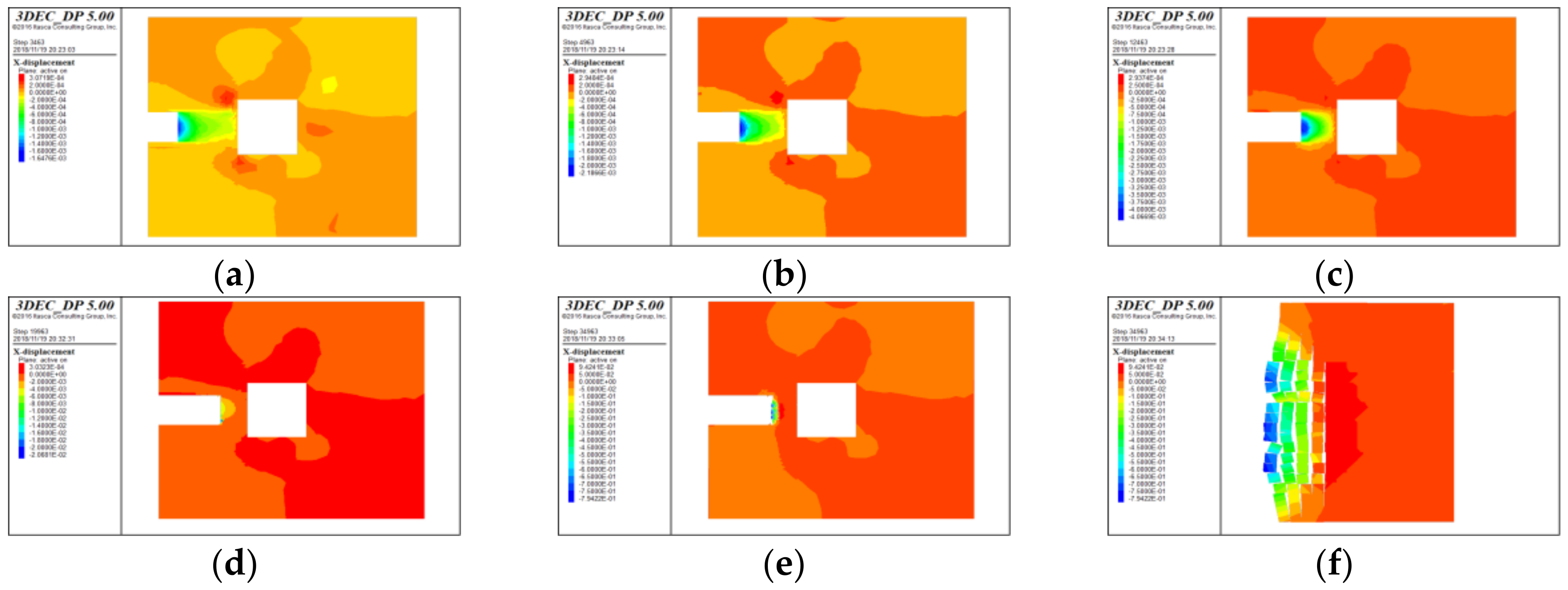
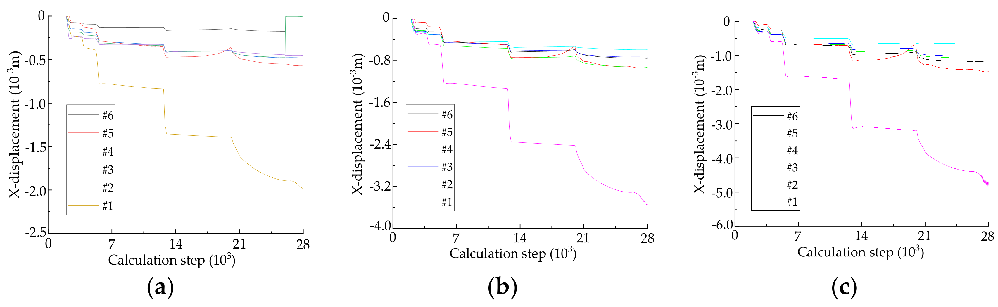
4.2.1. Analysis of Catastrophic Process of Water Inrush

Figure 9 shows the displacement field of water-resistant strata in the process of karst tunnel excavation (taking the large cavity as an example). The displacement shown in the diagrams is that the mode calculated to equilibrium state after each excavation, and the sixth diagrams are the local displacement of water-resistant strata. From Figure 9 we can see that: (1) The maximum displacement of the first excavation is equal to the second excavation, and the displacement of the third and the fourth excavation is twice as much as that of previous excavation, which show that the transition from the single effect of unloading on the extrusion displacement of karst tunnel face to combined action of unloading and karst water pressure occurs with the tunnel face advance. (2) After the early excavation step has completed, the displacement of the tunnel face on the longitudinal section of the tunnel axis is nearly symmetrical, and the effect of non-persisted joints at an angle of 45° with the direction of the maximum principal stress is not obvious, indicating that the non-persisted joints have not cracked or slid and the water-resistant strata is still stabilized. (3) When the thickness of water-resistant strata is 8 m, there exists a visible destruction area within a certain area under the effect of excavation unloading and high pressure fracture water, and the damage degree of the middle and lower part of the tunnel face is slightly greater than that of the upper part with the local displacement reached to 0.85 m.
In the process of sequential excavation to approach the high-pressure cavity, monitoring sections are set at distances of 2 m (x = −2), 4 m (x = −4), 6 m (x = −6), 7 m (x = −7), and 8 m (x = −8) from cavity respective. In addition, six monitoring points are arranged on each monitoring section shown in Figure 8. Taking the monitoring section of x = −4 as an example, the coordinates of the 6 measuring points are #1 (−4, 0, 0), #2 (−4, 0, 5), #3 (−4, 4.85, 1.62), #4 (−4, 5, 0), #5 (−4, −5, 0), and #6 (−4, 4.94, −1.85) respectively. The X-displacement of each monitoring point under each monitoring section is shown in Figure 10. The reason for taking 28,000 steps is to show the stages of the displacement with the development of the tunnel excavation, and the differences of the displacement of each measuring point, which can be reflected in Figure 10f.
It can be concluded from Figure 10 that: (1) The X-displacement of each measuring point on different monitoring section has obvious response with the sequential excavation. The displacement value of each measuring point is different, but the change regulation is the same basically. (2) During the tunnel excavation, the X-displacement of each monitoring point increases continuously. Moreover, the increasing range of monitoring points displacement raises and the need of computational steps to keep model balance also increases with the distance between karst cavity and tunnel face decrease. (3) On the same monitoring section, the displacement of # 1 is much larger than those of other monitoring points. Combined with Figure 9, it can be summarized that the maximum deformation of water-resistant strata appears at the geometric center of the tunneling face in this model. (4) From Figure 10f we can see that the displacement of #1 increases suddenly after fifth excavation, which indicated that it has obvious instability characteristics and water inrush premonition. It could be considered that the water-resistant strata rock mass is instability failure at this time, and it is consistent with the destruction of water-resistant strata after the fifth excavation in Figure 9.
The formation process of water inrush pathway is shown in Figure 11 during tunnel excavation.
As illustrated in Figure 11, after the first and second step of tunnel excavation, the karst water enters the crack connected with the karst. At this time, the karst water is basically maintained in the water-resistant strata affected by the furthest right column fracture, and the seepage of water-resistant strata near tunnel face is not obvious. After the third tunnel excavation, the influence of the water pressure starts to appear. With the water pressure of furthest right column fracture increase, the rock bridge between first column fracture and second column fracture begins to spilt and connect. After the fourth excavation, karst water appeared in the rock bridge between the second and third column fracture. Small-scale water inrush occurred in the tunnel face under the effect of seepage pressure, and the water pressure is less than 0.6 MPa. After the fifth excavation, the unstable failure of water-resistant strata occurs and the water inrush pathway forms under the combined influence of excavation unloading and hydraulic pressure.

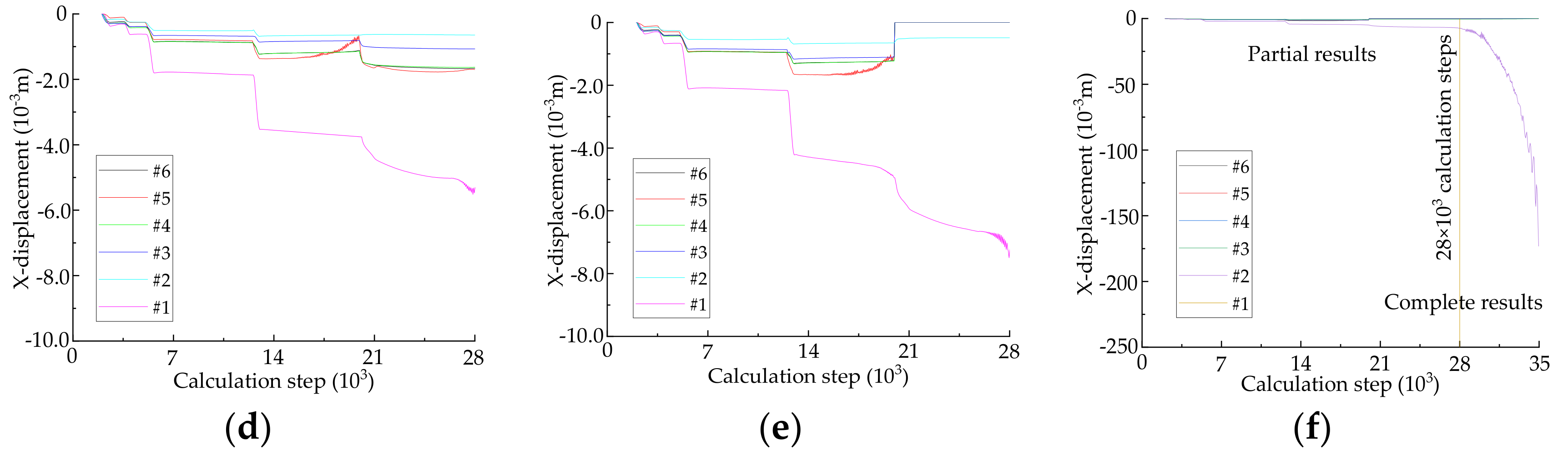
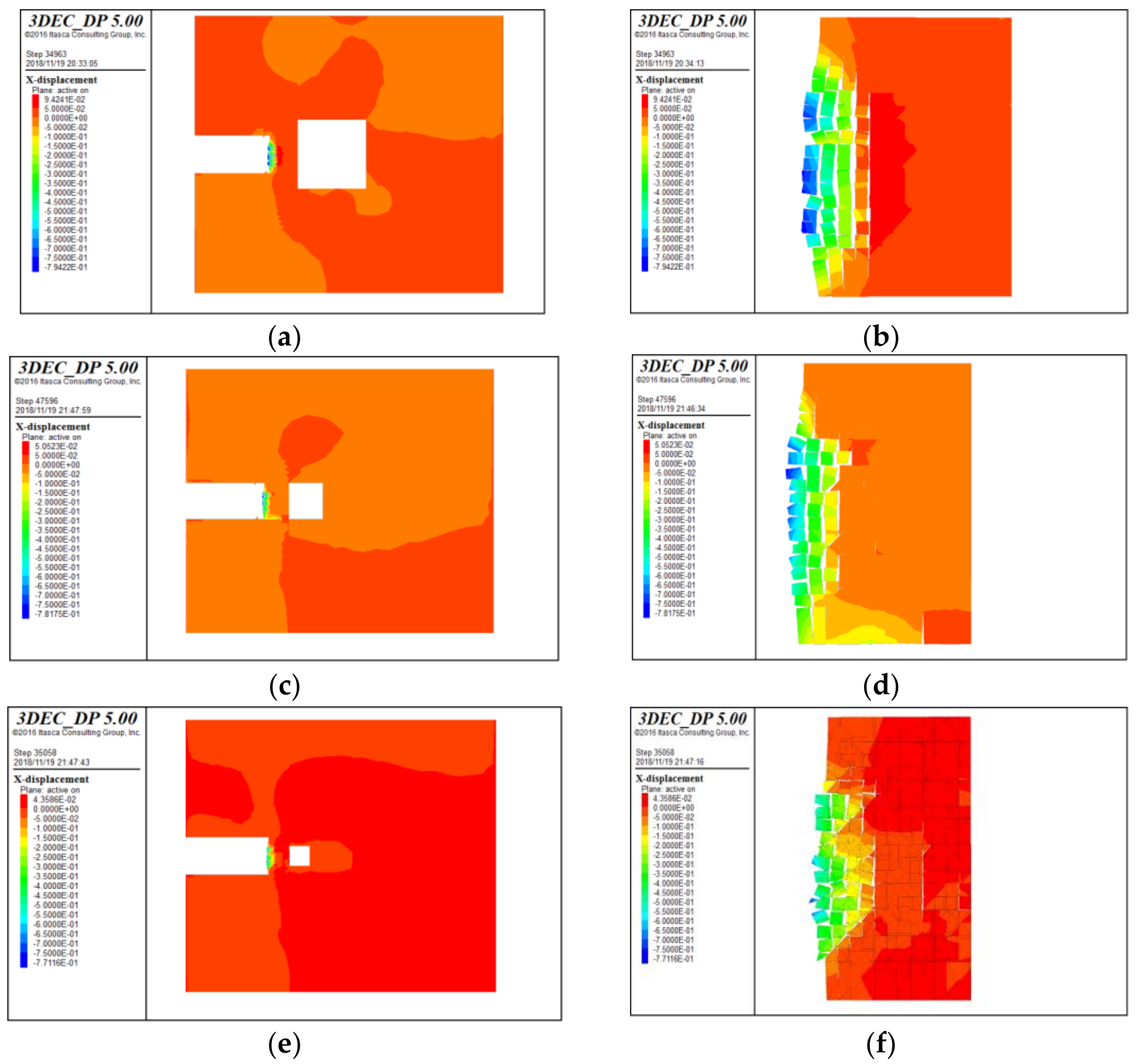
4.2.2. Influence of Karst Cavity Scale on Water Inrush

In order to investigate the influence of the karst cavity scale on the displacement of the surrounding rock, the karst cavity size is set with 6 m, 10 m, and 20 m diameter respectively, shown in Figure 8. The water pressure in the cavity is 2 MPa. Figure 12 is the local displacement nephogram of water-resistant strata under different karst cavity scale when it was destroyed.
It can be seen from Figure 12 that the water-resistant strata thickness is 8 m, 7 m and 6 m when it was destroyed in different karst cavity scale, which shows that the stability of rock mass decreases and the minimum safe thickness of water-resistant strata increases with the increase of karst cavity diameter. Moreover, the damage region in longitudinal extension of water-resistant strata increases with increasing volume of the karst cave, and the axial damage region of water-resistant strata is the same basically.
The maximum deformation of water-resistant strata appears at the geometric center of the tunneling face in the process of tunnel sequential excavation, therefore the X-displacement of the center point of tunnel face under different karst cavity scale is drawn in Figure 13. Figure 13a shows the X-displacement of the center monitoring points on monitoring sections of x = −6. Figure 13b shows the X-displacement of center monitoring points on monitoring sections of x =−7. Figure 13c shows the displacement of tunnel center monitoring point after each excavation under different karst cavity scale.
It can be seen from Figure 13a,b that when the water-resistant strata is destroyed, the displacement of monitoring points near the tunnel face change suddenly. For example, in the large cavity, the monitoring point displacement increase rapid when the calculation step is about 28,000. For medium karst, the calculation step is 35,000. For small karst, the calculation step is about 48,000. Moreover, the X-displacement of catastrophe point increases with the increase of karst cavity scale. It can be concluded from Figure 13c that the displacement of the center of tunnel face increase with the tunnel sequential excavation. If the karst diameter is larger than others, the water inrush would be occurred firstly under the same karst water pressure. These phenomena indicate that with the increase of karst scale, the stability of water-resistant strata decreases gradually, the rock mass of water-resistant strata is easy to be deformed, and the karst tunnel is more likely to be destroyed under karst water pressure and stress.
In the course of tunnel excavation, the fluid velocity and fluid pressure after each excavation is drawn in curves. The maximum fluid velocity after excavation is shown in Figure 14. The fluid pressure of different monitoring point under different karst cavity size are shown in Figure 15.
It can be seen from Figure 14 that in the early stage of tunnel excavation, the tunnel face is far from the cavity and the tunnel excavation has little influence on crack, the width of the crack is almost unchanged. Meanwhile, the karst water enters the crack continuously, which leads to the increase of the water pressure in the crack and the decrease of the water pressure difference between the crack and the cavern. So, the fluid velocity decreases continuously. After the fourth excavation step, the tunnel face is close to the cavity. Then the cracks expand continuously and the width of cracks also increase under the effect of excavation disturbance and karst water pressure, which leads the water pressure to decrease and the fluid velocity to increase. It can be also concluded from the diagram that the fluid velocity increases with the increase cavity diameter.
It can be seen from Figure 15 that the tunnel excavation has little effect on the crack because the tunnel face is far from the fracture zone in the early stage of tunnel excavation, and the water pressure of the monitoring points in the water-resistant strata increase gradually with the continuous tunnel excavation. After fourth excavation step, the tunnel face is close to the fracture zone and the crack initiation and propagation under the combined effect of excavation unloading and karst water pressure, which leads to the water pressure decrease. Then the water pressure of fracture increase under the recharge of karst water. We can also know that with the increase of the cavity diameter, the water pressure at the same monitoring point also increases in the same karst pressure. It proves that the scale of the karst could affect the fluid flow velocity.

5. Conclusions

(1)
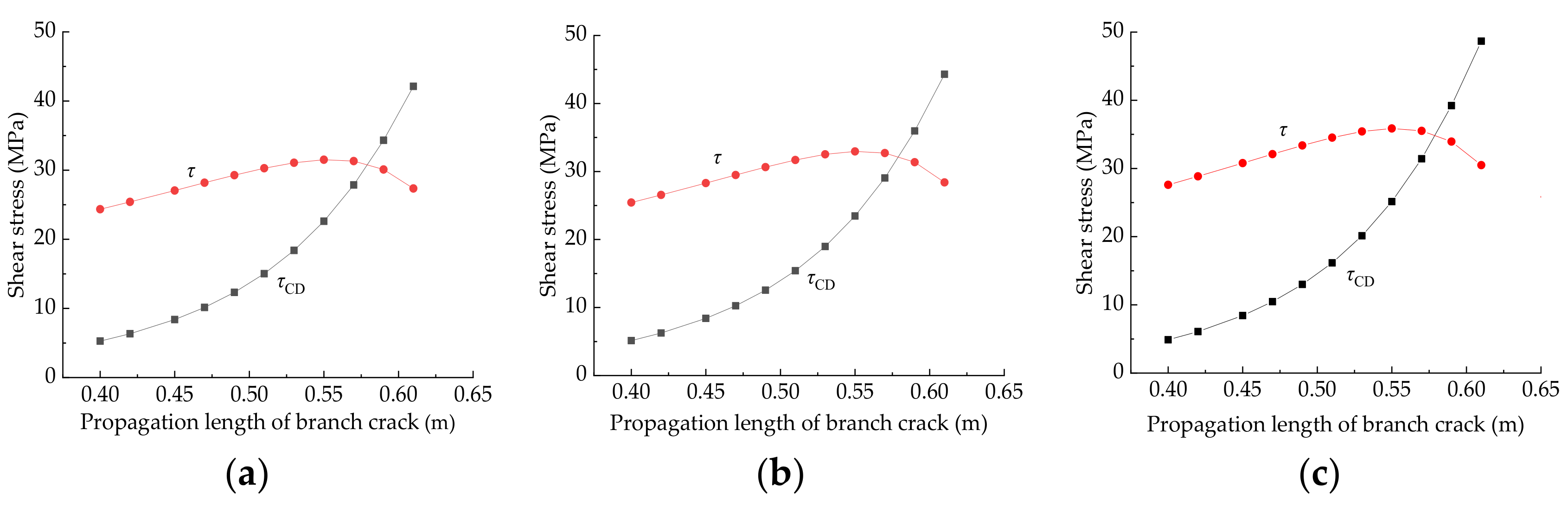
The rock mass with non-persistent joints is a common type of tunnel surrounding rock mass. The water inrush model for the fractured rock mass is usually hydraulic fracturing, and the model of hydraulic fracturing for rock mass with multi fractures is compression shear failure under karst water pressure and geo-stress. With the increase of the crack propagated length, the shear stress of rock bridge increases. Based on the Mohr-Coulomb strength criterion and the shear stress condition of rock bridge, the formula of critical water pressure for rock mass with multi fractures when it occurs the tension-shear combined fracturing failure is deduced.
(2)
The water-resistant strata ahead of karst tunnel face can be divided into karst initial fissure zone and karst hydraulic fracturing zone. Based on the two-band theory and the critical water pressure, the formula to determine the minimum safe thickness of water-resistant strata with multi fractures is established. The minimum safety thickness increases with the increase of initial crack length and karst water pressure, and decreases with the increase of crack distance (d and h), lateral pressure coefficient. As the angle between the initial crack and the maximum principal stress increases, the minimum safety thickness increases firstly and then decreases.
(3)
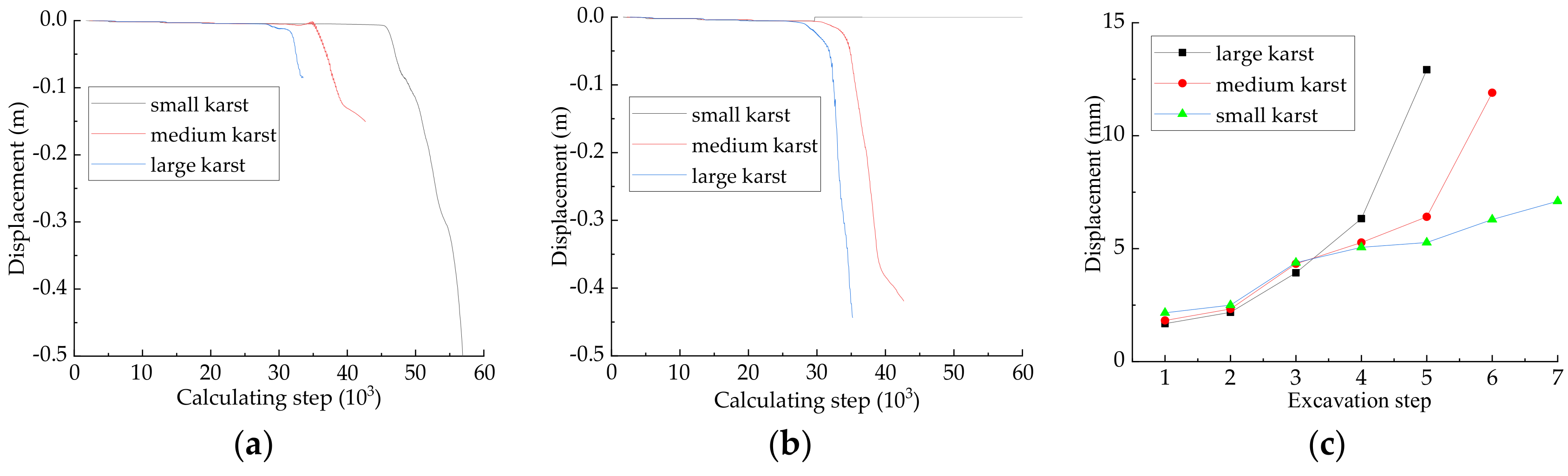
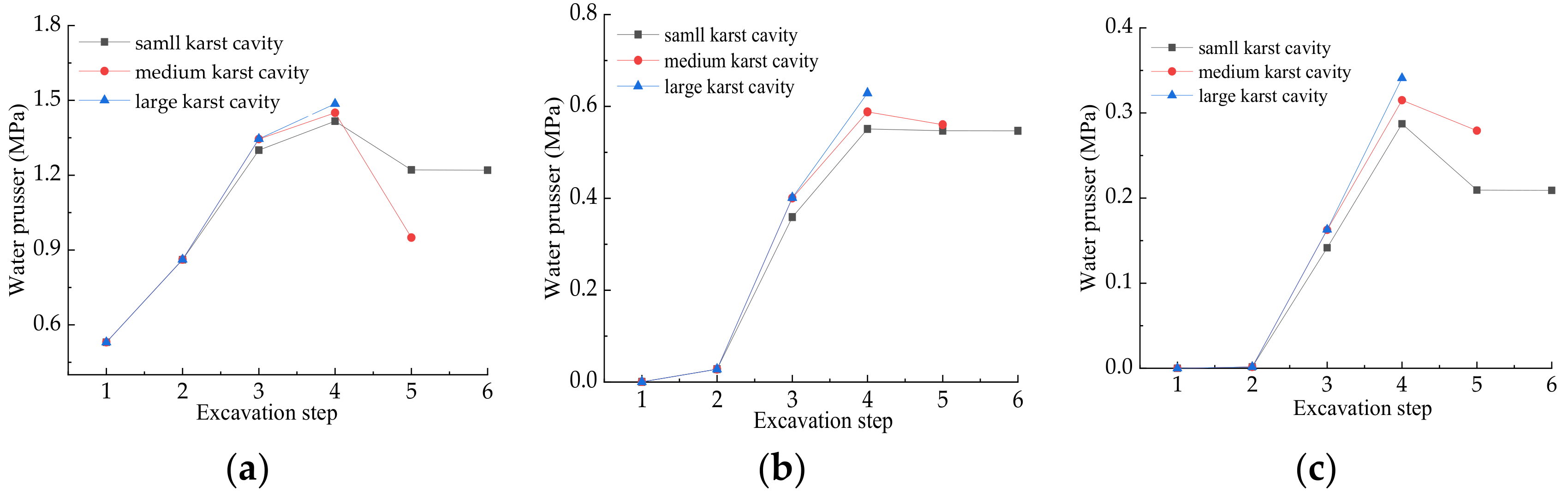
3D discrete element method is used to study the catastrophe process of water inrush in the water-resistant strata with multi fractures during tunnel excavation. The change from the single effect of unloading on the extrusion displacement of karst tunnel face to combined action of unloading and karst water pressure occurs in process of tunnel face close to karst cavity; The extrusion displacement and water flow velocity in tunnel face suddenly rise before the water inrush pathway forms, which is the important precursory information for water inrush disaster. With the increase of karst cavity scale, the water pressure of same monitoring point increase at the same time, and the minimum safe thickness of water-resistant strata also increases.

Author Contributions

Conceptualization, J.G. and J.C.; methodology, J.G. and Y.Q.; validation, J.G.; investigation, Y.Q. and F.C.; data curation, J.G. and J.C.; writing—original draft preparation, J.G. and Y.Q.; writing—review and editing, J.G. and F.C.; supervision, J.G. and J.C.; funding acquisition, J.G.

Funding

This research was funded by the National Natural Science Foundation of China (Grant No. 51778215), the Chinese National Programs for Fundamental Research and Development (973 Program) (Grant No.2013CB036003) and China Postdoctoral Science Foundation funded project (Grant No. 2018M631114).

Acknowledgments

The authors greatly appreciate the financial supports from funding bodies, and would be grateful to the reviewers for their valuable comments and suggestions to improve the quality of the paper.

Conflicts of Interest

The authors declare no conflict of interest.

References

  1. Fraldi, M.; Guarracino, F. Limit analysis of collapse mechanisms in cavities and tunnels according to the Hoek-Brown failure criterion. Int. J. Rock Mech. Min. Sci. 2009, 46, 665–673. [Google Scholar] [CrossRef]
  2. Fraldi, M.; Guarracino, F. Analytical solutions for collapse mechanisms in tunnels with arbitrary cross sections. Int. J. Solids Struct. 2010, 47, 216–223. [Google Scholar] [CrossRef]
  3. Yang, Z.H.; Zhang, J.H. Minimum safe thickness of rock plug in karst tunnel according to upper bound theorem. J. Cent. South Univ. 2016, 23, 2346–2353. [Google Scholar] [CrossRef]
  4. Guo, J.Q.; Chen, J.X.; Chen, F.; Huang, S.X.; Wang, H.Y. Using the Schwarz alternating method to identify critical water-resistant thickness between tunnel and concealed cavity. Adv. Civ. Eng. 2018, 2018, 8401482. [Google Scholar] [CrossRef]
  5. Xu, Z.H.; Wu, J.; Li, S.C.; Zhang, B.; Huang, X. Semianalytical solution to determine minimum safety thickness of rock resisting water inrush from filling-type karst caves. Int. J. Geomech. 2018, 18, 4017152. [Google Scholar] [CrossRef]
  6. Gan, K.R.; Yang, Y.; Jiang-She, L.I. Analysis on karst water inflow mechanisms and determination of thickness of safe rock walls: Case study on a tunnel. Tunn. Constr. 2007, 28, 13–16. [Google Scholar] [CrossRef]
  7. Li-Ping, L.I.; Wei, L.U.; Shu-Cai, L.I.; Zhang, Q.S.; Zhen-Hao, X.U.; Shi, S.S. Research status and developing trend analysis of the water inrush mechanism for underground engineering construction. J. Shandong Univ. 2010, 40, 104–112. [Google Scholar]
  8. Guo, J.Q.; Qiao, C.S. Study on water-inrush mechanism and safe thickness of rock wall of karst tunnel face. J. Chin. Railw. Soc. 2012, 34, 105–111. [Google Scholar] [CrossRef]
  9. Wu, Q.; Wang, M.; Wu, X. Investigations of groundwater bursting into coal mine seam floors from fault zones. Int. J. Rock Mech. Min. Sci. 2004, 41, 557–571. [Google Scholar] [CrossRef]
  10. Li, S.C.; Wu, J.; Xu, Z.H.; Zhou, L.; Zhang, B. A possible prediction method to determine the top concealed karst cave based on displacement monitoring during tunnel construction. Bull. Eng. Geol. Environ. 2019, 78, 341–355. [Google Scholar] [CrossRef]
  11. Wang, C. Study on Risk Identification and Warning of Karst Water Bursting Disaster of Railway Tunnel. Ph.D. Thesis, Beijing Jiaotong University, Beijing, China, 1 July 2015. [Google Scholar]
  12. Sterpi, D.; Cividini, A. A physical and numerical investigation on the stability of shallow tunnels in strain softening media. Rock Mech. Rock Eng. 2004, 37, 277–298. [Google Scholar] [CrossRef]
  13. Jiang, C.X.; Shi, H.P.; Li, Y.; Yu, H.M. Numerical simulation of groundwater under complex karst conditions and the prediction of roadway gushing in a coal mine: A case study in the Guang’an Longtan reservoir in Sichuan province, China. Acta Geochim. 2016, 35, 72–84. [Google Scholar] [CrossRef]
  14. Parise, M.; Lollino, P. A preliminary analysis of failure mechanisms in karst and man-made underground caves in Southern Italy. Geomorphology 2011, 134, 132–143. [Google Scholar] [CrossRef]
  15. Geng, P.; Quan, Q.; Wang, S. Study of the formation process of mud and water bursts during tunnel construction and the influence of fault dip angles. Mod. Tunn. Technol. 2015, 52, 102–109. [Google Scholar] [CrossRef]
  16. Liu, S.; Liu, H.; Wang, S.; Hu, B.; Zhang, X. Direct shear tests and PFC2D numerical simulation of intermittent joints. Chin. J. Rock Mech. Eng. 2008, 27, 1828–1836. [Google Scholar] [CrossRef]
  17. Cai, M. Influence of intermediate principal stress on rock fracturing and strength near excavation boundaries—Insight from numerical modeling. Int. J. Rock Mech. Min. Sci. 2008, 45, 763–772. [Google Scholar] [CrossRef]
  18. Yang, S.Q. Crack coalescence behavior of brittle sandstone samples containing two coplanar fissures in the process of deformation failure. Eng. Fract. Mech. 2011, 78, 3059–3081. [Google Scholar] [CrossRef]
  19. Kemeny, J.M. A model for non-linear rock deformation under compression due to sub-critical crack growth. Int. J. Rock Mech. Min. Sci. Geomech. Abstr. 1991, 28, 459–467. [Google Scholar] [CrossRef]
  20. Li, Y.P.; Chen, L.Z.; Wang, Y.H. Experimental research on pre-cracked marble under compression. Int. J. Solids Struct. 2005, 42, 2505–2516. [Google Scholar] [CrossRef]
  21. Kachanov, M. On the problems of crack interactions and crack coalescence. Int. J. Fract. 2003, 120, 537–543. [Google Scholar] [CrossRef]
  22. Bobet, A.; Einstein, H.H. Fracture coalescence in rock-type materials under uniaxial and biaxial compression. Int. J. Rock Mech. Min. Sci. 1998, 35, 863–888. [Google Scholar] [CrossRef]
  23. Liu, T.; Cao, P.; Lin, H. Damage and fracture evolution of hydraulic fracturing in compression-shear rock cracks. Theor. Appl. Fract. Mech. 2014, 74, 55–63. [Google Scholar] [CrossRef]
  24. Li, S.C.; Yuan, Y.C.; Li, L.P.; Ye, Z.H.; Zhang, Q.Q.; Lei, T. Water inrush mechanism and minimum safe thickness of rock wall of karst tunnel face under blast excavation. Chin. J. Geotech. Eng. 2015, 37, 313–320. [Google Scholar] [CrossRef]
  25. Wang, X.; Wang, M. Analysis of mechanism of water inrush in Karst tunnels. In Proceedings of the American Society of Civil Engineers GeoShanghai International Conference 2006, Shanghai, China, 6–8 June 2006; pp. 66–72. [Google Scholar] [CrossRef]
  26. Li, L.P.; Li, S.C.; Zhang, Q.-S. Study of mechanism of water inrush induced by hydraulic fracturing in karst tunnels. Rock Soil Mech. 2010, 31, 523–528. [Google Scholar]
  27. Zhong, X.U.; Deng, H.; Deng, S.; Guoxiang, T.U.; Wan, K. Study on formation mechanism of water gushing in karst tunnel and safety thickness of rock wall. Yangtze River 2018, 49, 61–66. [Google Scholar] [CrossRef]
  28. Wang, J.X.; Zhu, H.H.; Tang, Y.Q.; Yang, L.Z. Fracture mechanical model and hydrochemical-hydraulic coupled damage evolution equation of limestone. J. Tongji Univ. 2004, 32, 1320–1324. [Google Scholar] [CrossRef]
  29. Olson, J.E.; Taleghani, A.; DahiTaleghani, M. Modeling simultaneous growth of multiple hydraulic fractures and their interaction with natural fractures. In Proceedings of the SPE hydraulic fracturing technology conference, The Woodlands, TX, USA, 19–21 January 2009; pp. 1–7. [Google Scholar] [CrossRef]
  30. Wu, K.; Olson, J.E. A simplified three-dimensional displacement discontinuity method for multiple fracture simulations. Int. J. Fract. 2015, 193, 191–204. [Google Scholar] [CrossRef]
  31. Vahab, M.; Khalili, N. X-fem modeling of multizone hydraulic fracturing treatments within saturated porous media. Rock Mech. Rock Eng. 2018, 51, 3219–3239. [Google Scholar] [CrossRef]
  32. Itasca Consulting Group Inc. 3UEDC (3 Dimension Distinct Element Code); Itasca: Minneapolis, MN, USA, 2011. [Google Scholar]
Figure 1. Research area of karst tunnel water-resistant strata stability in karst strata. (a) Conceptual model of karst geomorphological strata; (b) Conceptual model for stability study of water-resistant strata of karst tunnel.
Processes 07 00686 g001
Figure 2. Comparison between the critical water pressures of two splitter failure modes.
Processes 07 00686 g002
Figure 3. Two-dimensional (2D) simplification of rock mass with multi fracture and its mechanical model. (a) The 2D simplification of rock mass with multi fracture; (b) The mechanical model of rock mass with multi fracture.
Processes 07 00686 g003
Figure 4. Tension-shear combined failure characteristics of rock bridge.
Processes 07 00686 g004
Figure 5. Shear stress and shear strength of rock bridge under different propagation length of branch crack. (a) p = 0.5 MPa; (b) p = 1 MPa; (c) p = 2 MPa.
Processes 07 00686 g005
Figure 6. Sketch of minimum safe thickness of water-resistant strata ahead of karst tunnel face.
Processes 07 00686 g006
Figure 7. Relationship between minimum safe thickness of water-resistant strata and their influential factors. (a) Relationship between Smin and a; (b) Relationship between Smin and d; (c) Relationship between Smin and h; (d) Relationship between Smin and p; (e) Relationship between Smin and λ; (f) Relationship between Smin and ψ.
Processes 07 00686 g007aProcesses 07 00686 g007b
Figure 8. Simplification numerical calculation model based on discrete element. (a) The karst cavity diameter is smaller than tunnel; (b) The karst cavity diameter is equal to tunnel (c) The karst cavity diameter is larger than tunnel.
Processes 07 00686 g008
Figure 9. Displacement field evolution of water-resistant strata ahead of karst tunnel face in excavation process. (a) First excavation; (b) Second excavation; (c) Third excavation; (d) Fourth excavation; (e) Fifth excavation; (f) Partial enlarged drawing of tunnel face for fifth excavation.
Processes 07 00686 g009
Figure 10. Displacement change of each point in water-resistant strata ahead of karst tunnel face in excavation process. (a) The monitoring section of x = −2; (b) The monitoring section of x = −4; (c) The monitoring section of x = −6; (d) The monitoring section of x = −7; (e) The monitoring section of x = −8; (f) The monitoring section of x = −8.
Processes 07 00686 g010aProcesses 07 00686 g010b
Figure 11. Water inrush pathway evolution in water-resistant strata ahead of karst tunnel face in excavation process. (a) Calculation step = 3463; (b) Calculation step = 4963; (c) Calculation step = 12,463; (d) Calculation step = 19,963; (e) Calculation step = 29,963.
Processes 07 00686 g011
Figure 12. Displacement nephogram of each water-resistant stratum when it was destroyed. (a) Large cavity; (b) Partial enlarged drawing for tunnel face with a large cavity; (c) Medium cavity; (d) Partial enlarged drawing for tunnel face with a medium cavity; (e) Small cavity; (f) Partial enlarged drawing for tunnel face with a small cavity.
Processes 07 00686 g012
Figure 13. The changing displacement of monitoring points in the process of tunnel excavation. (a) Displacement of monitoring point −6,0,0; (b) Displacement of monitoring point −7,0,0; (c) Displacement of tunnel face center.
Processes 07 00686 g013
Figure 14. The change of fluid velocity during tunnel excavation.
Processes 07 00686 g014
Figure 15. The fluid pressure of different monitoring points. (a) Fluid pressure of monitoring point −1,0,0; (b) Fluid pressure of monitoring point −3,0,0; (c) Fluid pressure of monitoring point −5,0,0.
Processes 07 00686 g015
Table 1. Strength and seepage parameters of rock in water-resistant strata.
Material PropertyBulk Modulus (GPa)Shear Modulus (GPa)Density (kg/m3)Friction (°)Cohesion (MPa)Tensile Strength (MPa)Joint Normal Stiffness (GPa/m)Joint Shear Stiffness (GPa/m)
Rock22.611.126.6420.860.45
Joint---300.860.018.66.2

