Article

An Intensified Reactive Separation Process for Bio-Jet Diesel Production

by
Miriam García-Sánchez
1,
Mauricio Sales-Cruz
2,
Teresa Lopez-Arenas
2,
Tomás Viveros-García
1 and
Eduardo S. Pérez-Cisneros
1,*
1
Departamento de Ingeniería de Procesos e Hidráulica, Universidad Autónoma Metropolitana-Iztapalapa, Av. San Rafael Atlixco No. 186, Col. Vicentina, Ciudad de México C.P. 09340, Mexico
2
Departamento de Procesos y Tecnología, Universidad Autónoma Metropolitana-Cuajimalpa, Avenida Vasco de Quiroga No. 4871, Colonia Santa Fe, Delegación Cuajimalpa de Morelos, Ciudad de México C.P. 05300, Mexico
*
Author to whom correspondence should be addressed.
Processes 2019, 7(10), 655; https://doi.org/10.3390/pr7100655
Submission received: 17 June 2019 / Revised: 13 September 2019 / Accepted: 23 September 2019 / Published: 25 September 2019

Abstract

:
An intensified three-step reaction-separation process for the production of bio-jet diesel from tryglycerides and petro-diesel mixtures is proposed. The intensified reaction-separation process considers three sequentially connected sections: (1) a triglyceride hydrolysis section with a catalytic heterogeneous reactor, which is used to convert the triglycerides of the vegetable oils into the resultant fatty acids. The separation of the pure fatty acid from glycerol and water is performed by a three-phase flash drum and two conventional distillation columns; (2) a co-hydrotreating section with a reactive distillation column used to perform simultaneously the deep hydrodesulphurisation (HDS) of petro-diesel and the hydrodeoxigenation (HDO), decarbonylation and decarboxylation of the fatty acids; and (3) an isomerization-cracking section with a hydrogenation catalytic reactor coupled with a two-phase flash drum is used to produce bio-jet diesel with the suitable fuel features required by the international standards. Intensive simulations were carried out and the effect of several operating variables of the three sections (triglyceride-water feed ratio, oleic acid-petro-diesel feed ratio, hydrogen consumption) on the global intensified process was studied and the optimal operating conditions of the intensified process for the production of bio-jet diesel were achieved.

1. Introduction

The area of process system engineering (PSE) has been rapidly developing since the 1950s, reflecting the remarkable growth of the oil, gas, petrochemical and biotechnological industries and their increasing economical and societal impact. It can be said that the roots of this field go back to the Sargent’s pioneering school in United Kingdom [1,2]. Modelling, simulation and optimization (MSO) of large-scale (product or process) systems is a core technology to deal with the complexity and connectivity of chemical processes and their products at multiple scales [3,4]. These technologies have been implemented in easy-to-use software systems that allow the systematic solution for problem solving practitioners. The systematic (explicit or implicit) generation, evaluation and integration of a comprehensive set of design alternatives is considered a key concern for the optimal design. This systematic integration associates the PSE strongly with its traditional focus in complete plants for both, process intensification [5,6] and to chemical product design [7]. Specifically, process intensification involves the development of novel apparatuses and techniques that, in comparison with those commonly used, are expected to bring enhancements in manufacturing and processing, substantially reducing the equipment-size/production-capacity ratio, energy consumption, or waste production, and ultimately resulting in cheaper, sustainable technologies [5]. Also, it is known that the whole scope of process intensification generally can be divided into two areas: (i) process-intensifying equipment, such as novel reactors, and exhaustive mixing, heat and mass transfer devices and, (ii) process-intensifying methods, such as new or hybrid separations, integration of reaction and separation, heat exchange or phase transition (i.e., reactive distillation), techniques using alternative energy sources (light, ultrasound, etc.), and new process-control methods (such as intentional unsteady-state operation).
The concerns about energy demand are obliging the oil-based fuels consumer countries to reconsider their energy policies to promote the investigation on trustworthy alternatives to conventional fuels. Thus, the bio-jet diesel has arisen as an alternative for petro-diesel jet fuels used in the aviation enterprises. Specifically, for the jet fuel, the International Air Transport Association (IATA) estimated that the consumption of the jet diesel would increase every year by 5% till 2030 [8]. Also, due to the growing of the flight demand and the strong regulations to diminish the CO2, IATA established a carbon neutral reduction up to 50% by 2050. In this way, the bio-jet fuel obtained from vegetable oils of from mixtures of vegetable oils and petro-diesel, can be contemplated as one of the most favourable solutions to satisfy the global demand. To now, there has been identified four main routes to obtain the bio-jet diesel: (i) oil-to-jet (deoxygenation of triglyceride and consequent hydrocracking), [9] (ii) gas-to-jet (gasification/Fischer-Tropsch reaction followed by hydrocracking), [10] (iii) alcohol-to-jet (dehydration of alcohols and successive oligomerization), [11] and (iv) sugar-to-jet (several catalytic conversions of sugars) [12]. Table 1 shows the key conversion steps, the catalyst used, the companies producing the jet-fuel and the feedstocks considered for each route to obtain bio-jet fuel.
For the conversion of oil to bio-jet fuel (OTJ), different type of oil feedstock has various converting pathways. The common pathways include the hydrogenated esters and fatty acids (HEFA) and catalytic hydrothermolysis (CH). The feedstocks for HEFA are non-edible vegetable oils, used cooking oil, and animal fats. While the feedstocks for CH are algal oils or oil plant. HEFA is a process to hydrotreat the triglycerides, saturated or unsaturated fatty acids in the non-edible vegetable oils, used cooking oils and animal fats to produce bio-jet fuels. The process is generally divided into two steps. The first step is converting unsaturated fatty acids and triglycerides into saturated fatty acid by catalytic hydrogenation, the triglycerides occur a β-hydrogen elimination reaction to yield a fatty acid during the process. The saturated fatty acid is converted to C15–C18 straight chain alkanes by hydrodeoxygenation and decarboxylation. The co-products are propane, H2O, CO and CO2. The early-developed catalysts for this step are noble metals supported with zeolites or oxides, and later shifted to other transition metals, such as Ni, Mo, Co, Mo or their supported bimetallic composites due to catalyst deactivation by poisoning, production of cracking species and process costs. The second step of HEFA is the cracking and isomerization reactions: the deoxygenated straight chain alkanes are further selectively hydrocracked and deep isomerized to generate highly branched alkanes mixed liquid fuels. The common catalysts for this step are Pt, Ni or other precious metals supported by activated carbon, Al2O3, zeolite molecular sieves. The bio-jet fuels produced by HEFA, as high energy biofuels, can be directly used in flight engine even without blending. The fuel has high thermal stability, good cold flow behaviours, high cetane number, and low tailpipe emissions, while has low aromatic content, which would cause fuel low lubricity and fuel leakage problems. Another pathway to convert algal or oil plant to jet fuel is CH, which is also named hydrothermal liquefaction (HTL). The integrated process has three steps, including pretreatment of triglycerides, CH conversion and post-refining steps. The pretreatments including conjugation, cyclization, and cross-linking, which are aiming to improve the molecular structures. The products undergo a cracking and hydrolysis reaction with the help of water and catalysts. Then it occurs catalytic decarboxylation and dehydration during the CH process. Last, post-refining hydrotreating and fractionation are designed to convert straight-chain, branched and cyclo-olefins into alkanes. The conversion process of lignocellulosic biomass to jet-fuel have advantages in lowering cost, feasible availability and no competition with food supplies. Hydroprocessed depolymerized cellulosic jet (HDCJ) is an oil upgrading technology to convert bio-oils produced from the pyrolysis or hydrothermal of the lignocellulose into a jet fuel by hydrotreating. The main technology for bio-oil upgrading is a two-step hydroprocessing. First, the bio-oil is hydrotreated with the help of catalyst under mild conditions. Organic could be used to promote hydrodeoxygenation of bio-oil and overcome coke formation. Second, conventional hydrogenation setup and catalyst were used under high temperature for obtaining hydrocarbon fuel. The HDCJ process could produce high aromatic content, low oxygen content and few impurities jet fuel. However, there is high hydrogen consumption and deoxygenation requirements in this process, which can make a considerable expense. Moreover, the short catalyst lifetime and modest hydrocarbon yields can be challenges for used in aviation.
For the conversion of gas to bio-jet fuel (GTJ) the Fischer-Tropsch (FT) process has been commercially implemented. Fischer-Tropsch (FT) is a process to produce liquid hydrocarbon fuels from syngas. The common process for FT could be divided into six procedures: feedstock pretreatments, biomass gasification, gas conditioning, acid gas removal, FT synthesis and syncrude refining. The FT synthesis can also be divided into high temperature FT and low temperature FT. The temperature for high temperature FT is around 310–340 °C, and the products are main gasoline, solvent oil and olefins; the temperature for low temperature FT is around 210–260 °C, the products are main kerosene, diesel oil, lubricating base oil and naphtha fractions. Too low temperature of FT will format high quantities of methane as a by-product. Typical pressures of FT process are in the range of one to several tens of atmospheres. The high pressures will result the formation of long-chain alkanes. The FT fuel is free of sulphur, nitrogen, has high specific energy, high thermal stability, and cause low emissions when used for aviation. However, the disadvantages for the fuel are low aromatic content and less energy density, which would also cause a low efficiency and high production cost for the process.
For the conversion of sugar to bio-jet fuel (STJ) the biotechnological process of convert sugars to alkane-type fuels directly instead of firstly converting to ethanol intermediate, which is called Direct Sugar to Hydrocarbons (DSHC) has been implemented commercially (see Table 1). The feedstock for the DSHC are similar to the feedstock of ethanol production, including the sugar cane, beets and maize. DSHC is a process to produces alkane-type fuels directly from sugars via fermentation. It is different from the alcohol to jet pathway, which needs an alcohol intermediate. The technology is developed based on the development of genetic engineering and screening technologies that enable to modify the way microbes metabolize sugar. A complete conversion process of DSHC, involving six major steps: pretreatment and conditioning, enzymatic hydrolysis, hydrolysate clarification, biological conversion, product purification and hydroprocessing has been proposed [13]. The DSHC has a low energy input due to the low temperature of the fermentation, while the fuel blend is limited (10%) and not meet some performances standards and it is also identified as more suitable for production high-value chemicals.
Finally, the conversion route to convert alcohols to bio-jet fuel (ATJ) use several processes depending of the feedstock. The process of production hydrocarbons in the jet fuel range from the alcohols generally undergoes a four-step upgrading process. First is the alcohol dehydration to generate olefins, then the olefins are oligomerised in the presence of catalysts to produce a middle distillate. Next, the middle distillates are hydrogenated to produce the jet-fuel-ranged hydrocarbons and a final step is the distillation to purify the bio-jet fuel product. Commercial production always use ethanol, butanol and isobutanol to be the intermediate to converse biomass to jet fuel. The economics of alcohol to jet process is mainly affected by the way to produce alcohol, while the biochemistry way has relatively smaller minimum jet fuel selling price (MJSP), the sugar cane and starch are suitable feedstock from an economics prospective. Complete reviews of the technologies described above considering the techno-economic analysis are given in [14,15,16,17].
Considering the above technologies, the (i) oil-to-jet and (ii) gas-to-jet are contemplated as the most convincing alternatives in the short term. In fact, the bio-jet fuels produced with these technologies are now allowed by ASTM specification D7566-14 for blending into commercial jet fuel at concentrations up to 50% [18]. Recently [19], a hydrotreating reactive distillation column (RDC) for the production of green-diesel from sulphured petro-diesel and non-edible vegetable oils mixtures was proposed. From this work, it was concluded that the deep hydrodesulphurisation (HDS) of petro-diesel is strongly affected by feeding high amounts of triglycerides to the RDC, while it is not affected when only fatty acids are fed. Also, an integrated reactive separation process for the production of jet-diesel was developed but the assumptions about the conversion of tryglycerides to fatty acids and the yield of isomerization-cracking of the linear hydrocarbon chains lead to an oversimplified reactive separation process [20]. Therefore, in this work, from a process intensification context, an innovative intensified three-step reactive separation process for bio-jet diesel production is proposed.
Thus, the intensified three-step reactive separation process consist of: (1) a triglyceride hydrolysis section where a catalytic heterogeneous reactor is used to convert the triglycerides to the resultant fatty acids, followed by a three-phase separation device and a sequence of two distillation columns to obtain pure fatty acid and glycerol; (2) a hydrotreating section with a reactive distillation column used to simultaneously carried out the deep hydrodesulphurisation (HDS) of petro-diesel and the hydrodeoxigenation, decarbonylation and decarboxylation of the fatty acids; and (3) an isomerization-cracking section with a hydrogenation fixed bed reactor connected to a two phase flash separator to produce bio-jet diesel with the required fuel properties. It should be pointed out that the conversion and yield assumptions used in [20] are not considered here and the appropriate reaction kinetics found in the open literature [21,22] is used to perform the rigorous simulation of the intensified process.

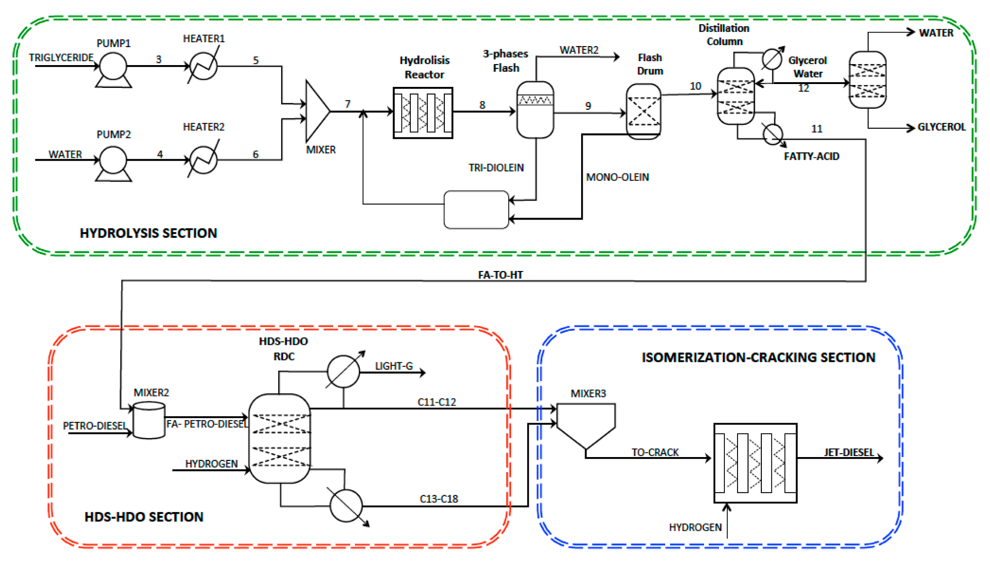
2. The Intensified Reactive Separation Process

The production of bio-jet fuel can be described by the subsequent reactions (see Figure 1): (i) hydrogenation of the C=C bonds present in the tryglycerides, (ii) hydrogenolysis of the tryglycerides to produce the respective fatty acids, (iii) deoxygenation of the resultant fatty acids to obtain n-paraffins and (iv) hydroisomerization and hydrocracking of the n-paraffins to produce a mixture containing mainly isomerized shorter chains (i-C8i-C16) that are appropriate as jet fuel. The first three reactions can be carried out using a metal catalyst or a MoS2-based catalyst. For the hydroisomerization and hydrocracking reaction (iv), a metal/acid bifunctional catalyst is recommended. Figure 1 shows the reaction pathways for the hydroconversion of tryglycerides into bio-jet fuel. It has been shown [23] that the direct hydrogenation of tryglycerides may be very expensive due to the price of the hydrogen at high pressures. Thus, the conventional hydrolysis of tryglycerides with high pressure steam is preferred. An alternative to the hydrogenation and hydrolysis at high pressure is to use a heterogeneous hydrolysis catalytic reactor [24] at moderated pressures. Thus, in the present work this technological alternative is considered.
Figure 2 shows a simplified flow sheet of the intensified three-step reactive separation process for bio-jet diesel production. The first section (hydrolysis) consists of two pumps operating from 1 to 30 atm and two heat exchangers where the exit temperature is set to 280 °C. The heterogeneous hydrolysis reactor operates at 30 atm and it consists of two 25 m length tubes with 0.5 m of diameter. Further, a sequence of a three-phase flash and a two-phase drum are used to separate the fatty acid-glycerol-water mixture and the unconverted glycerides that are recycled to the hydrolysis reactor. Finally, two distillation columns are used to separate the pure fatty acid from a low concentration glycerol-water mixture and to produce pure glycerol. The second section, hydrodesulphurisation-hydrodeoxigenation (HDS-HDO) consists of a reactive distillation column (RDC) where a mixture of petro-diesel and fatty acid is fed to the RD column at stage 9 and excess hydrogen is fed at the bottom. The gases produced by the HDS-HDO reactions are released from the two-phase condenser. The exit liquid mixture of C11–C12 linear hydrocarbon chains is mixed with the exit stream containing C17–C18 hydrocarbons produced by the HDO reactions and the ultra-clean petro-diesel products. The third section consists of a heterogeneous hydro-conversion reactor where the long linear hydrocarbon chains (C11–C18) are isomerized and cracked to attain the bio-jet diesel.

2.1. The Triglycerides Hydrolysis Section

Vegetable oils and fats have been considered as one of the most used renewable raw materials in the chemical industry. These can be hydrolyzed to produce free fatty acids (FFA) with a high degree of purity to be used in the synthesis of chemically pure compounds [25]. However, in the present work, the proposed technological alternative to produce bio-jet fuel considers non-edible oils, waste oils and animal fats as feedstock, which are not in conflict with food resources. Fatty acids are used in a wide variety of industries, for example in the pharmaceutical and cosmetics industry. Also, fatty acids can be utilised to produce n-alkane chains through a decarboxylation process [26]. These hydrocarbons work properly in internal combustion engines as substitutes for petro-diesel. Actually, the hydrolysis of fats and vegetable oils, composed mainly of triglycerides, has been practiced in the industry for many years. In general, the hydrolysis of the esters occurs through the acyl-oxygen break [27] with an excess of water at high temperature or using an appropriate acid catalyst to hydrolyze the glycerol pillar in the ester group of any triglyceride (TG), diglyceride (DG) or monoglyceride (MG) [28]. The result of the hydrolisis reactions is the production of three moles of FFA and one mole of glycerol (Gly). In this work, triolein is considered as the main triglyceride compound and oleic acid as the correspondent fatty acid. The three consecutive reversible reactions can be written as:
triolein + H2O ⇔ diolein + oleic acid
diolein + H2O ⇔ mono-olein + oleic acid
mono-olein + H2O ⇔ glycerol + oleic acid
Commonly, the pure fatty acids are obtained from the reaction of vegetable oils and/or animal fats with superheated steam. The commercial hydrolisis conditions are around 100–260 °C and 10–7000 kPa using a 0.4–1.5 wt % water-to-oil ratio. Several variants of this technology have been used by industry [29,30]. In this work, the hydrolisis kinetics reported in the open literature [21] is used for the numerical simulation of the catalytic reactor using tungstated zirconia (WZ) and the solid composite SAC-13 as catalyst.

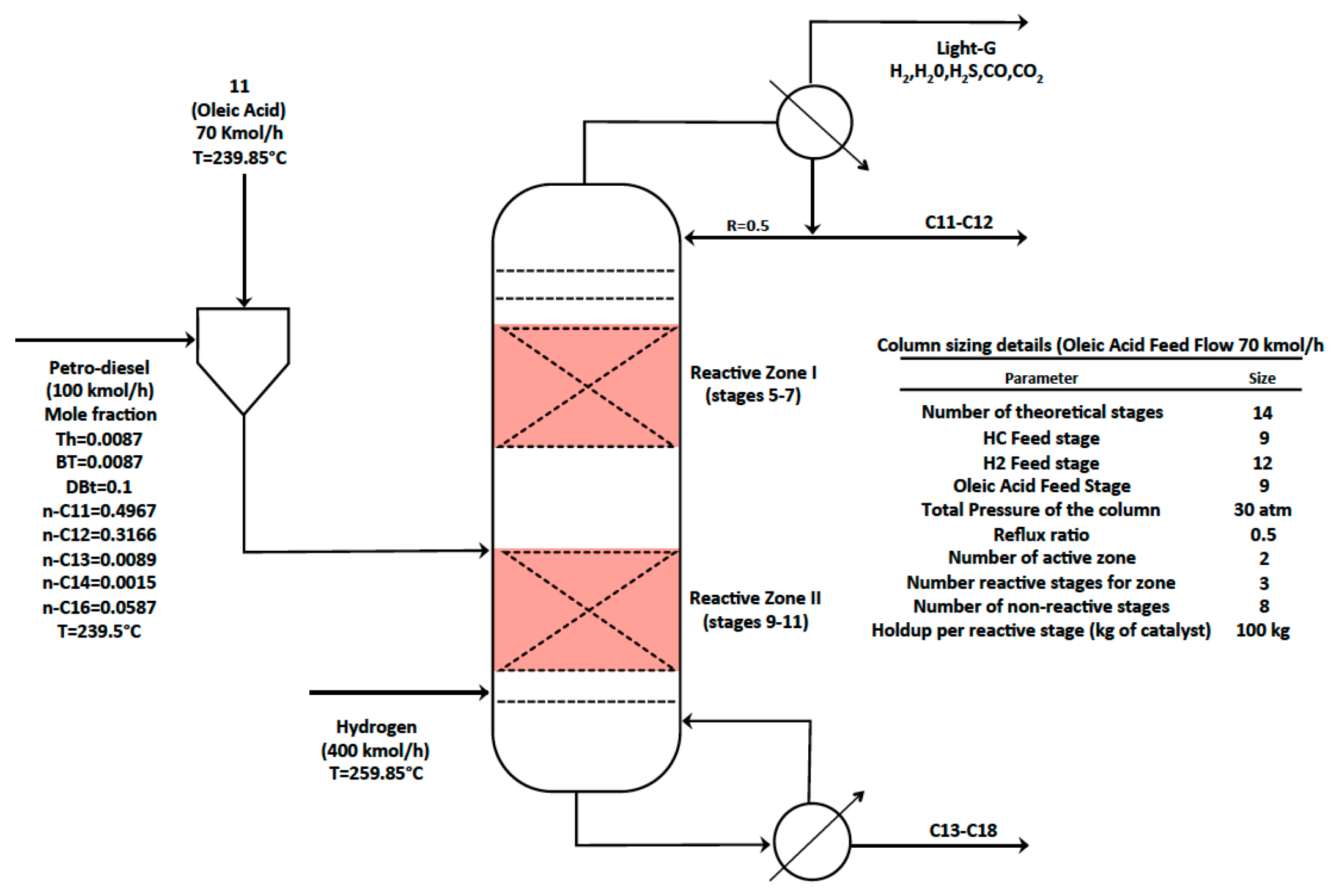
2.2. The HDS-HDO Reactive Distillation Section

The hydrotreatment of non-edible vegetable oils, waste oils or animal fats, this is, oils and fats that are not used for food and others medical applications, to produce renewable fuels has several advantages: (i) flexibility in the disposal of raw materials due to the great variety of oils available from vegetables on the earth; (ii) the process can be carried out using the existing infrastructure in petro-refineries and (iii) the bio-fuels produced can be used in conventional internal combustion machines since these bio-fuels have properties similar to those obtained from mineral oil [31]. The hydrotreatment of vegetable oils can be accomplished using traditional catalysts, for example with NiMo/Al2O3 catalysts. The hydrotreatment mainly produces n-paraffins through the hydrodecarboxylation, hydrodecarbonylation and hydrodeoxigenation reactions. From the refining point of view, the hydrodecarboxylation reaction is better than the hydrodeoxygenation reaction since it consumes less hydrogen. However, the large amount of CO (or CO2) generated represents a problem for refining, since CO2 can form carbonic acid with liquid water [32]. This means that the risk of carbonic corrosion of the reactive separation equipment is a key design problem. In general, vegetable oils can be hydrotreated as pure compounds or can be mixed with petro-diesel to be co-hydrotreated, in such a way that the hydrodesulphurisation (HDS) and hydrodeoxygenation (HDO) reactions are carried out simultaneously in a single unit. Therefore, the reactions considered for the HDS of the sulphured petro-diesel can be written in a simplified form as:
Thiophene (Th) + 2 H2 → Butadiene + H2S
Benzothiophene (BT) + 3 H2 → Ethylbenzene + H2S
DBT + 2 H2 → Biphenyl + H2S
For the HDS reactions only the hydrogenolysis reaction pathway is considered (Equation (6)). The simplified HDO reactions of the oleic acid can be written as:
C18H34O2 + 4 H2n-C18H38 + 2 H2O (hydrodeoxygenation)
C18H34O2 + 2 H2n-C17H36 + H2O + CO (decarbonylation)
C18H34O2 + H2n-C17H36 + CO2 (decarboxylation)
The reaction rate equations for the HDS reactions can be obtained from [19] and, due to the absence of reliable kinetic expressions for the complex HDO reactions, a 99% conversion of oleic acid is assumed.

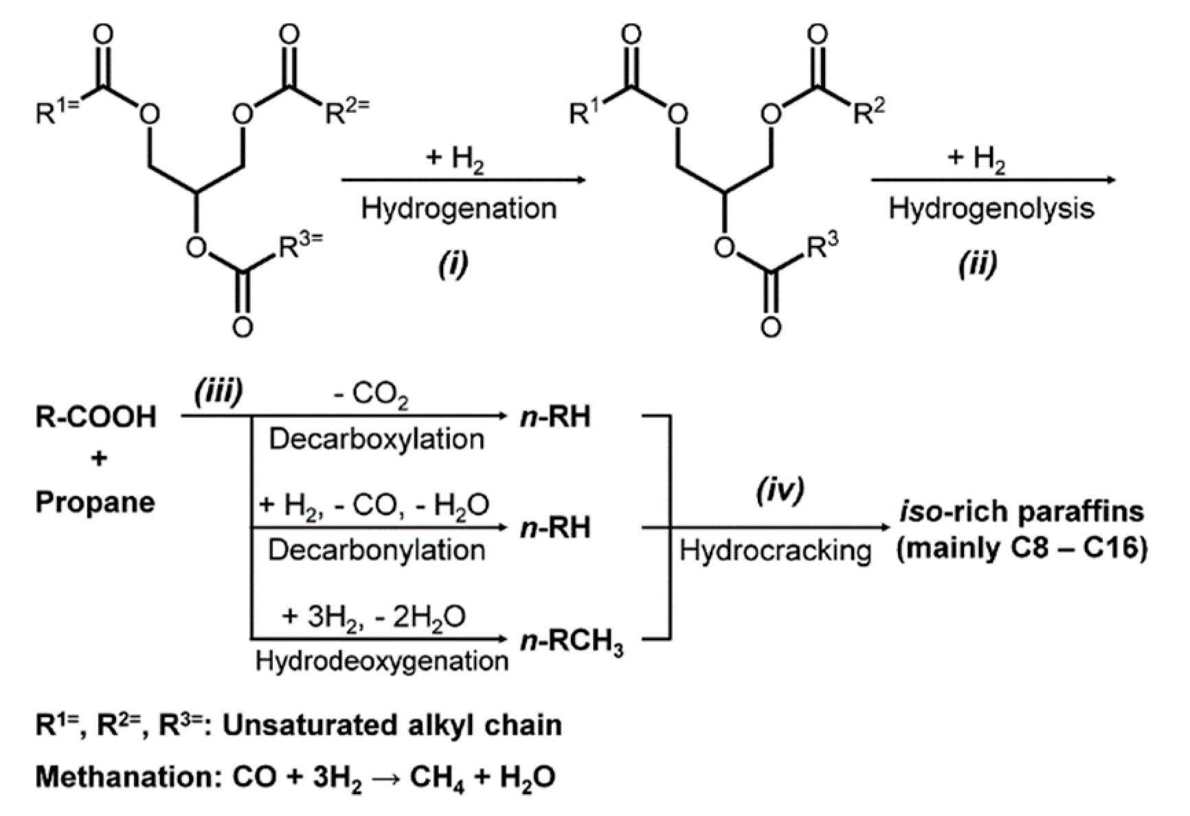
2.3. The Isomerization-Hydrocracking Section

In general the processes of isomerization and cracking through hydrogenation occur simultaneously. When hydrogenation favours isomerization it is called hydro-isomerization and when it promotes cracking it is called hydro-cracking. Depending on the characteristics of the hydrocarbon chains to be hydrotreated, the selection of the appropriate catalyst for this purpose can be made in a wide range of possibilities [33]. Specifically, for the production of jet diesel, the catalysts are bifunctional and are characterized by having acid sites that allow the selective function of isomerization and cracking simultaneously. Experimental evidence [34] indicate that the conversion of the n-paraffins can be described by the following reactions network:
Processes 07 00655 i001
where each single reaction is irreversible and follows a pseudo first-order kinetic. (A) is the concentration of the n-paraffin; (B) is the concentration of the iso-paraffin; (C), (D) and (E) are the concentrations of the cracking products. Following the linear reaction sequence path: A-->B-->C the hydro-conversion reactions could be written as:
n-C11H24i-C11H24
n-C12H26i-C12H26
n-C13H28i-C13H28
n-C14H30i-C14H30
n-C16H34i-C16H34
n-C17H36i-C17H36 + H2i-C8H18 + i-C9H20
n-C18H38i-C18H38 + H2i-C8H18 + i-C10H22
The kinetic equations for the isomerization and cracking of the linear hydrocarbon chains were taken from [16] and a catalyst of Pt supported on a nano-crystalline large-pore BEA zeolite is used [28].

3. Results and Discussion

In order to determine the best operating conditions of the intensified three-step hydrotreating reactive-separation process, the effect of different design and operating variables on the performance of the global process was investigated and analysed through intensive simulations. The intensive simulations of the intensified hydrotreating reactive separation process were carried out in the commercial Aspen-Plus simulator environment. Thus, heat and mass transfer phenomena and mixing issues were not taken into account.

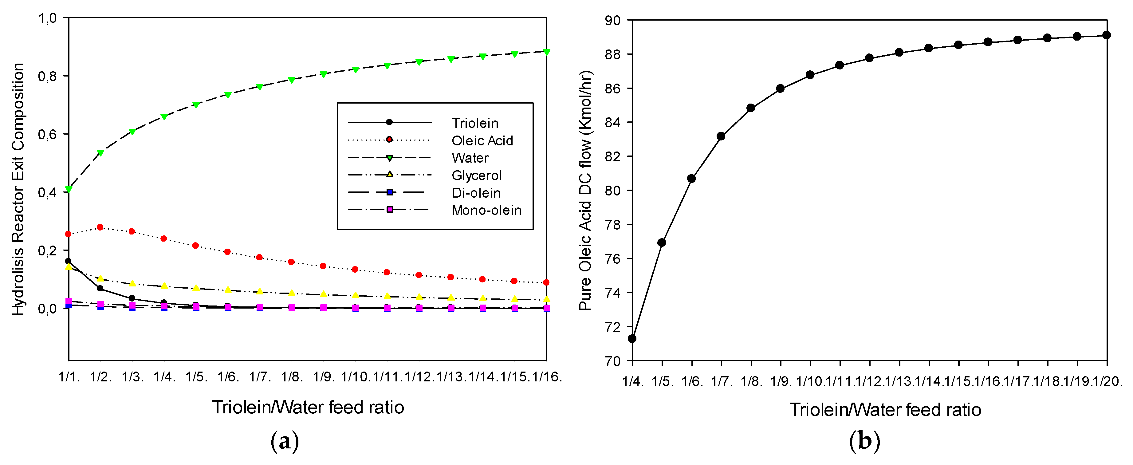
3.1. Hydrolysis Section

Different amounts of triolein-water feed ratio were used for the simulation of the intensified process. The numerical results shown in Table 2 are for the reference case (production of 70 kmol/h of pure oleic acid). From such numerical results it is found that total conversion of triolein is attained at 553 K and excess water (265 kmol/h). This water flow corresponds to 1/9 triolein/water feed ratio. The three-phase flash that separates water, oleic acid-water-glycerol and triolein-diolein mixture operates at 5 atm and 410 K, and the flash drum for the separation of the water-oleic acid-glycerol-unconverted glycerides operates at 1 atm. The two distillation columns to produce pure oleic acid and pure glycerol operate at 1 atm. It should be pointed out that the non-ideality of the reactive polar mixture is modelled using the RK-ASPEN equation of state.

Effect of the Triolein-Water Feed Ratio

The effect of the triolein-water feed ratio was studied in order to verify the maximum conversion of triolein to oleic acid. Figure 3a shows the effect of the feed ratio on the hydrolysis reactor exit composition. It can be observed that as the feed ratio increases, the triolein composition decreases to zero at 1/7 triolein-water feed ratio, approximately. However, it should be noted that, as the feed ratio increases, the hydrolysis reactor exit mixture contains less fatty acid (oleic acid). This is expected due to the excess of water fed to the reactor. Also, it can be observed that after a feed ratio of 1/7, the final reactor exit mixture contains only water, oleic acid and glycerol. Figure 3b shows the effect of the triolein-water feed ratio on the distillation column bottom flow (stream 11 in Figure 2). It can be noted in Figure 3b that as the feed ratio increases, the amount of oleic acid produced increases to a constant value of 88 (kmol/h). The production of 70 (kmol/h) at the bottom of the distillation column at a feed ratio of 1/9 has been taken as a reference study case.

3.2. HDS-HDO Section

In order to perform the deep hydrodesulphurisation of the sulphured petro-diesel and the reactions involved in the hydrodeoxigenation of the fatty acid, a two-zone reactive distillation column (RDC) is recommended [13]. Figure 4 shows the sizing details of the RDC, as well as the basic information for the simulation of the reference case. The RDC consists of 14 stages with two sections of reactive stages (5–7, 9–11) operating at 30 atm. It can be observed in Figure 4 that the liquid streams C11–C12 and C13–C18 contains mainly the larger linear hydrocarbon chains. Table 3 displays the numerical simulation results for the HDS-HDO section with 70 kmol/h of oleic acid and 100 (kmol/h) of petro-diesel fed at stage 9. Hydrogen feed was set to 400 (kmol/h) in order to accomplish full conversion of oleic acid and deep HDS of petro-diesel.

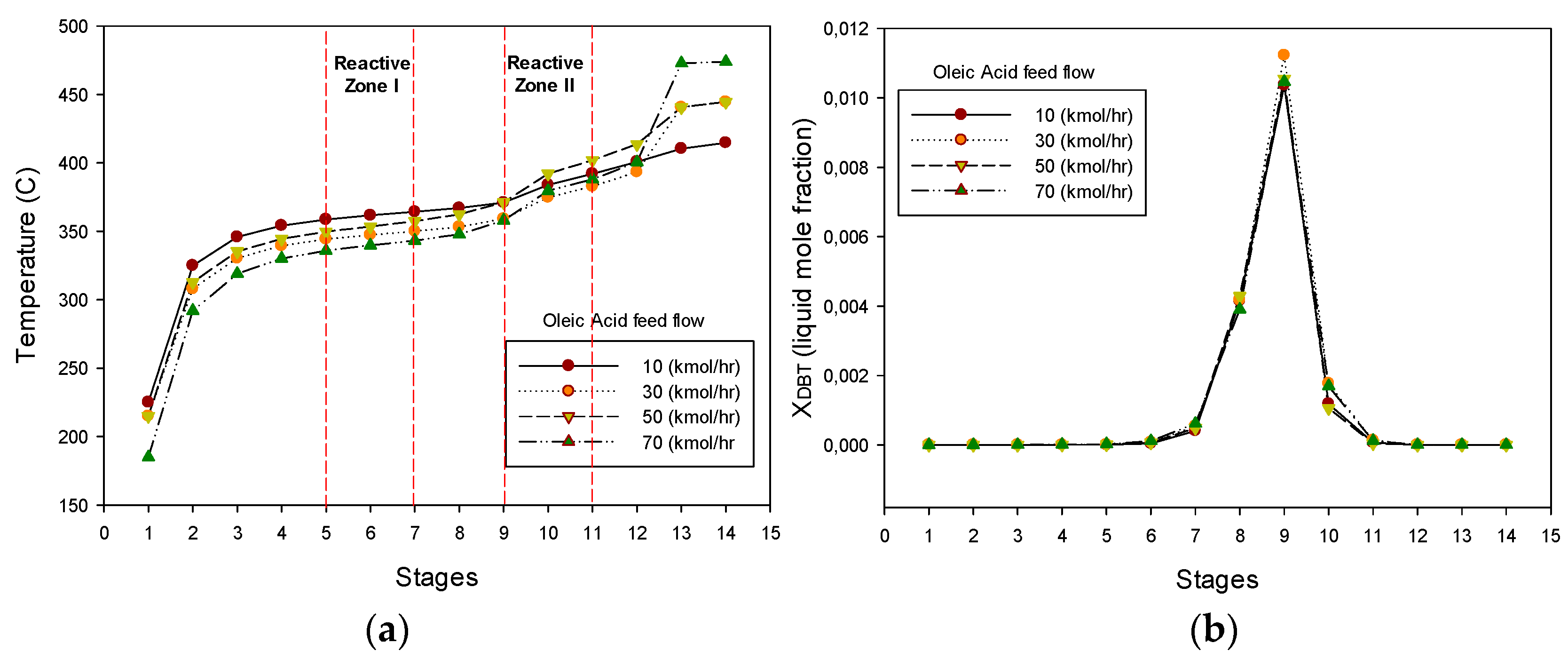
3.2.1. Effect of the Oleic Acid-Petro-Diesel Feed Ratio

The temperature profile along the reactive distillation column (RDC) assuming that oleic acid is premixed with the petro-diesel and fed in stage 9 is shown in Figure 5a. The co-hydrotreating process starts with a low concentration of oleic acid (10 kmol/h) in the mixture fed and it was continuously augmented up to 70 (kmol/h). It can be seen in Figure 5a that as the content of oleic acid increases, the temperature at the reactive zone I is reduced. The temperature reduction can be explained by considering that the boiling point of oleic acid is higher than the boiling point of most hydrocarbons present in the sulphured petro-diesel. The effect of the oleic acid composition in the feed on the deep HDS of the sulphured petro-diesel is shown in Figure 5b. It can be noted in Figure 5b that, even for a high content of oleic acid (70 kmol/h), the deep HDS of petro-diesel is accomplished. The analysis of these results leads to the conclusion that the performance of the reactive distillation column (RDC), initially used for deep hydrodesulphurisation of petro-diesel, is not affected by the introduction of a vegetable oil with a high content of fatty acid (oleic acid).

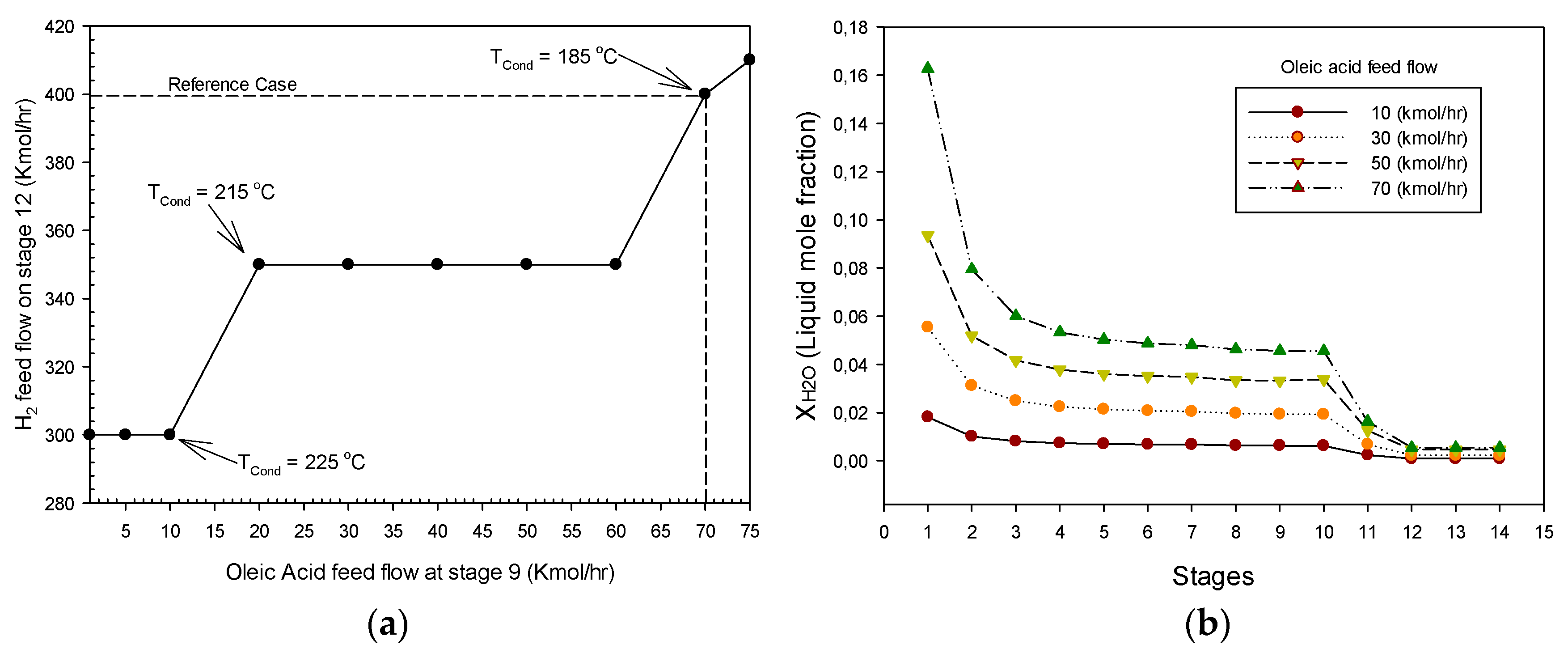
3.2.2. Hydrogen Consumption and Liquid Water Production

The molar flow of hydrogen required for the HDS and HDO reactions as a function of the oleic acid content in the feed is shown in Figure 6a. It can be noted in Figure 6a that, for an oleic acid feed flow greater than 10 (kmol/h), the temperature of the condenser is reduced to 215 °C, and for a feed flow of 70 (kmol/h), the required hydrogen is increased to 400 (kmol/h) and the temperature of the condenser should be diminished to 185 °C. It should be pointed out that, if the temperature of the condenser is not decreased, the numerical convergence of the RDC simulation is not reached. Thus, a control loop between the source of vegetable oil (oleic acid) and the hydrogen supplied should be linked to the temperature of the condenser. The liquid water composition profiles along the RDC for different oleic acid feed flows are shown in Figure 6b. It can be noted in Figure 6b that the concentration of liquid water increases from reactive zone I (steps 5–7) to the upper part of the RDC. Liquid water is mainly produced in reactive zone II (reactive stage 9–11) by the hydrodeoxygenation and decarbonylation reactions and its molar fraction increases continuously from stage 9 to the upper part of the RDC, as the concentration of oleic acid in the feed is augmented. Therefore, in order to minimize catalyst deactivation and corrosion of the RDC equipment, the amount of oleic acid in the mixture fed should not be higher than 70 (kmol/h).

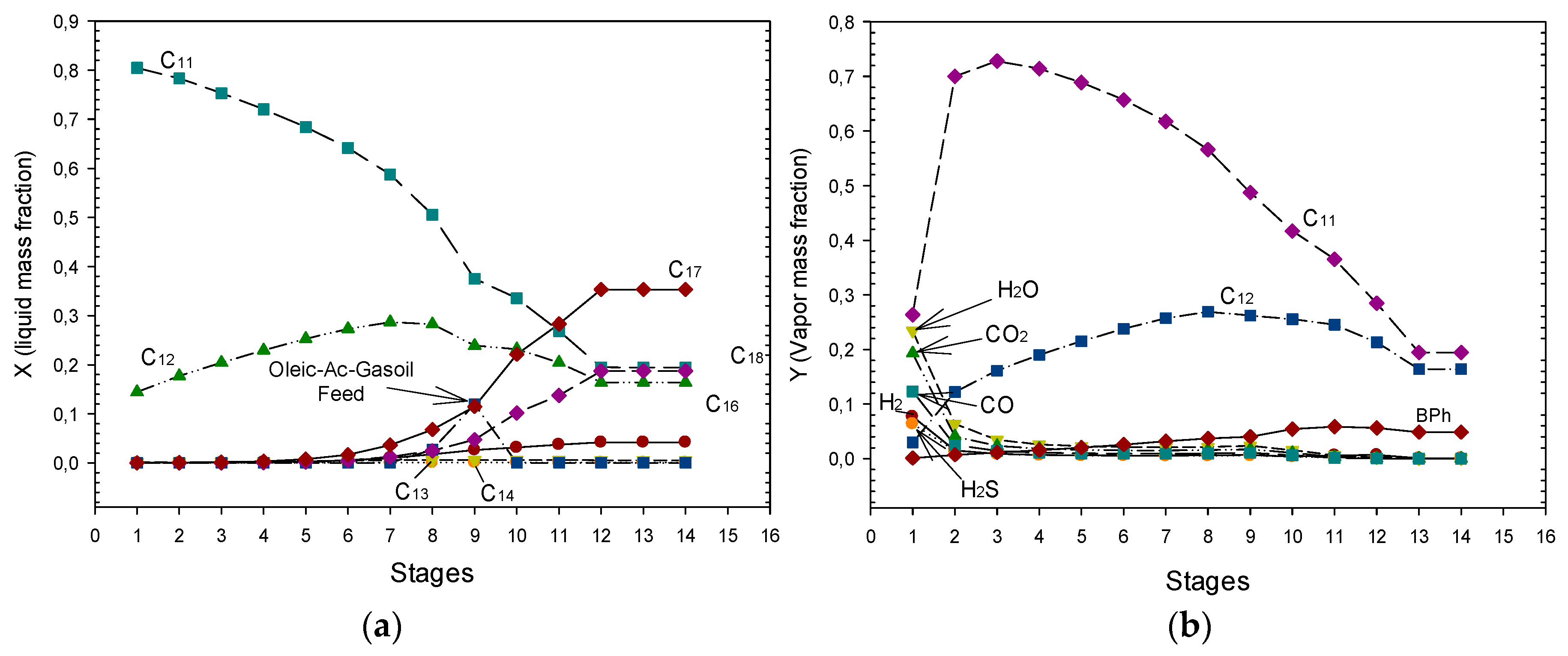
3.2.3. Hydrocarbon Distribution and Release of Generated Gases

Figure 7a shows the hydrocarbon liquid composition distribution. It can be noted in Figure 7a that the bottom exit stream contains mainly the linear hydrocarbons C17, C18, C16, C14, and C13. At the top of the RDC a rich liquid mixture of C11 and C12 linear hydrocarbons is obtained. It should be pointed out that such linear hydrocarbons (C11–C18) are further mixed and fed to the isomerization-hydrocracking reactor (see Figure 2). Figure 7b shows the gas composition profile along the RDC. In the case of the hydrotreating RDC, the gases produced are mainly driven in the vapour phase at each equilibrium stage and released from the partial condenser at the top of the RDC. It can be noted in Figure 7b that the gases produced by HDS and HDO reactions: CO2, CO, steam and H2S and the unconverted excess of hydrogen are released at the top of the column. It is interesting to observe that the vapour composition of C11 and C12 decreases at the top of the column.

3.2.4. Operability and Controllability of the HDO-HDS Reactive Distillation Section

Reactive distillation column mathematical models are highly nonlinear, and multiple steady states (MSS) solutions have been reported by many researchers [35,36,37]. However, none of these works have addressed the HDO-HDS reactive distillation process, most of them studied the MTBE and TAME cases. In the present work, the MSS solutions are only briefly described. Two multiplicity types can be found: input and output multiplicities, but a combined input–output multiplicity may also be present. Output multiplicity occurs when one set of input variables (manipulated variables) results in two or more unique and independent sets of output variables (measured variables). In chemical reactors and reactive distillation columns there are usually three steady states associated to ignition (high conversion), extinction (low conversion) and medium unstable conversion. On the other hand, input multiplicity occurs when two or more unique sets of input variables produce the same output condition. This type of multiplicity has important implications for close loop control since it is related to the so-called zero dynamics of the system, which is associated with unusual, unexpected, or inverse responses of the outputs after a step change, has been applied to the inputs. As RDC share some common features with chemical reactors and conventional (non-reactive) distillation columns, the RDC behavior may exhibit input–output multiplicity with three steady states or output multiplicity, with a large number of different steady states induced by ignition and extinction of every single reactive column tray [38]. Thus, in the present work, from the intensive simulation results, it was found that the reflux ratio is a key parameter for an appropriate RDC design and operation. Additionally, an increment in the hydrocarbon feed (sulphured diesel) flowrate leads to lower conversions of the organo-sulfur and fatty acid compounds with the reduction of the H2/HC feed ratio. In addition, it was found that, the DBT conversion was highly affected by the variations of the reboiler heat duty, while the fatty acid conversion was practically constant (~99%). However, DBT conversion design target (99.9%) was achieved at four different reboiler duties, indicating the existence of input-output multiplicities. It was also determined that the amount of catalyst loaded at the reactive zones must be greater than 8000 kg in order to achieve an ultra low sulfphur diesel (ULSD) production and a complete conversion of the fatty acids. This is, if a suitable excess of H2 is present in the reaction zones, the behavior of the RDC is very likely to a HDS conventional catalytic reactor. Therefore, it may be said that the multiplicities found in the intensive simulations are highly related to the specific phenomena (reaction-separation) involved. It should be pointed out that the accurate determination of the thermodynamic properties of all species participating in the reacting mixture must be taken carefully. The correct determination of the boiling points, critical properties, etc. of all species involved in the reactive separation process and the computation of the complex phase equilibrium in the intensified reactive separation process is a key step. This is, for example, for the HDO-HDS section, the inaccuracy of the property values (boiling point of the fatty acids) can lead to multiple steady states and unstable operation and control of the reactive distillation process. The analysis of the intensive simulation results suggest that, under optimal design and operating conditions, reactive distillation can be considered as a viable technological alternative to produce bio-jet diesel trough a RDC co-hydrotreating process.

3.3. The Isomerization-Cracking Section

The numerical simulation results with the final composition of the bio-jet diesel obtained in the hydro-conversion reactor are shown in Table 4. It should be mentioned that an excess of hydrogen must be fed to the reactor in turn to accomplish the complete isomerization and cracking of the longer hydrocarbon chains. The total pressure of the reactor is set at 80 atm and a 5:1 hydrogen-hydrocarbon feed ratio was considered. The exit stream from the isomerization-cracking reactor is further flashed to eliminate the hydrogen excess and the light hydrocarbons produced during the cracking step. The isomerization-cracking kinetics and reactor arrangement were taken from the open literature [34]. From Table 3 it can be observed that the bio-jet-diesel produced contains mainly i-C8 to i-C16 hydrocarbons indicating that a light bio-jet diesel is produced.

4. Conclusions

An intensified three-step hydrotreating reaction-separation process for the production of bio-jet diesel from triolein and petro-diesel mixtures has been developed. Through intensive simulations the effect of different operating variables (triglyceride-water feed ratio, oleic acid-petro-diesel feed ratio, hydrogen consumption) on the performance of the intensified reactive separation process was studied. By analysing the simulation results, it can be established that, a 1/9 triolein-water feed ratio guarantee the complete conversion of triolein to oleic acid at moderated pressures (30 atm) at the hydrolysis section. For the HDS-HDO section, it can be mentioned that a mixture containing up to 70 (kmol/h) of oleic acid in the hydrocarbon feed of the RDC is the optimal mixture composition in order to achieve the deep hydrodesulphurisation of petro-diesel. Also, with this mixture composition, any change to the basic structure (reactive and non-reactive stages) of the RDC is not required. It should be pointed out that the HDS-HDO RD column should operate at moderated pressures (30 atm) in order to allow the fast vaporization of the light gases produced and avoid the corrosion problem with carbonic acid generated by the reaction of CO or CO2 with water. For the isomerization and cracking section, a low-pressure flash separator, after the hydro-conversion reactor is required to eliminate the undesirable side products. Therefore, it can be concluded that the key design and operating parameters for the production of the bio-jet diesel are: (i) in the hydrolysis section, the water excess and the total pressure for the heterogeneous catalytic hydrolysis reactor; (ii) for the HDS-HDO section, if high molar flows of fatty acid are considered, it is mandatory to have more reactive stages in the HDS-HDO reactive distillation column in order to achieve ultra-clean (no-sulphur) petro-diesel at the bottom of the column. Finally, the absence of light compounds in the exit stream of the heterogeneous isomerization-cracking reactor is required in order to circumvent undesirable side products and reach the suitable fuel properties required by the international standards. Finally, the economic and sustainability analysis of the intensified reactive separation process to produce bio-jet diesel is being carried out.

Author Contributions

Conceptualization, M.S.-C. and E.S.P.-C.; Formal analysis, T.V.-G.; Investigation, E.S.P.-C.; Methodology, M.G.-S. and E.S.P.-C.; Software, T.L.-A.; Validation, M.S.-C. and T.V.-G.; Writing—original draft, M.G.-S.; Writing—review & editing, T.L.-A. and E.S.P.-C.

Funding

This research was funded by CONACyT PhD scholarship of Miriam García-Sánchez.

Conflicts of Interest

The authors declare no conflict of interest.

References

  1. Sargent, R.W.H. Integrated design and optimization of processes. Chem. Eng. Prog. 1967, 63, 71–78. [Google Scholar]
  2. Sargent, R.W.H. Forecasts and trends in systems engineering. Chem. Eng. 1972, 262, 226. [Google Scholar]
  3. Grossmann, I.E.; Westerberg, A.W. Research challenges in process systems engineering. AIChE J. 2000, 46, 1700–1703. [Google Scholar] [CrossRef]
  4. Pantelides, C.C. New challenges and opportunities for process modelling. In Computer Aided Chemical Engineering; Gani, R., Jorgensen, S.B., Eds.; Elsevier: Amsterdam, The Netherlands, 2001. [Google Scholar]
  5. Moulijn, J.A.; Stankiewicz, A.; Grievink, J.; Gorak, A. Process intensification and process systems engineering: A friendly symbiosis. Comput. Chem. Eng. 2008, 32, 3–11. [Google Scholar] [CrossRef]
  6. Zhang, L.; Babi, D.K.; Gani, R. New vistas in chemical product-Process design . Ann. Rev. Chem. Biomol. Eng. 2016, 7, 557–582. [Google Scholar] [CrossRef]
  7. Gani, R. Chemical product design: Challenges and opportunities. Comput. Chem. Eng. 2004, 28, 2441–2457. [Google Scholar] [CrossRef]
  8. Rosillo-Calle, F.; Teelucksingh, S.; Thrän, D.; Seiffert, M. IEA Bioenergy. 2012. Available online: http://task40.ieabioenergy.com/iea-publications/task-40-library/ (accessed on 22 July 2019).
  9. McCall, M.J.; Kocal, J.A.; Bhattacharyya, A.; Kalnes, T.N.; Brandvold, T.A. Production of Aviation Fuel from Renewable Feedstocks. U.S. Patent 8,039,682B2, 18 October 2011. [Google Scholar]
  10. Lamprecht, D. Fischer−Tropsch Fuel for Use by the U.S. Military as Battlefield-Use Fuel of the Future. Energy Fuels 2007, 21, 1448–1453. [Google Scholar] [CrossRef]
  11. Luning Prak, D.J.; Jones, M.H.; Trulove, P.; McDaniel, A.M.; Dickerson, T.; Cowart, J.S. Physical and Chemical Analysis of Alcohol-to-Jet (ATJ) Fuel and Development of Surrogate Fuel Mixtures. Energy Fuels 2015, 29, 3760–3769. [Google Scholar] [CrossRef] [Green Version]
  12. Olcay, H.; Subrahmanyam, A.V.; Xing, R.; Lajoie, J.; Dumesic, J.A.; Huber, G.W. Production of renewable petroleum refinery diesel and jet fuel feedstocks from hemicellulose sugar streams. Energy Environ. Sci. 2013, 6, 205–216. [Google Scholar] [CrossRef]
  13. Davis, R.; Biddy, M.J.; Tan, E.; Tao, L.; Jones, S.B. Biological Conversion of Sugars to Hydrocarbons Technology Pathway; Pacific Northwest National Lab.(PNNL): Richland, WA, USA, 2013. [Google Scholar]
  14. Wang, W.C.; Tao, L.; Markham, J.; Zhang, Y.; Tan, E.; Batan, L.; Warner, E.; Biddy, M. Bio-Jet Fuel Conversion Technologies. Review of Bio-Jet Fuel Conversion Technologies at 2016. NREL/TP-5100-66291. Available online: http://www.nrel.gov/publications (accessed on 13 January 2018).
  15. Douvartzides, S.L.; Charisiou, N.D.; Papageridis, K.N.; Goula, M.A. Green Diesel: Biomass Feedstocks, Production Technologies, Catalytic Research, Fuel Properties and Performance in Compression Ignition Internal Combustion Engines. Energies 2019, 12, 809. [Google Scholar] [CrossRef]
  16. Wang, W.C.; Tao, L. Bio-Jet fuel conversion technologies. Renew. Sustain. Energy Rev. 2016, 53, 801–822. [Google Scholar] [CrossRef]
  17. Martinez-Hernandez, E.; Ramírez-Verduzco, L.F.; Amezcua-Allieri, M.A.; Aburto, J. Process simulation and techno-Economic analysis of bio-Jet fuel and green diesel production—Minimum selling prices. Chem. Eng. Res. Des. 2019, 146, 60–70. [Google Scholar] [CrossRef]
  18. American Society for Testing and Materials; Standard Specification for Aviation Turbine Fuel Containing Synthesized Hydrocarbons; ASTM International: West Conshohocken, PA, USA, 2014.
  19. Perez-Cisneros, E.S.; Sales-Cruz, M.; Lobo-Oehmichen, R.; Viveros-García, T. A reactive distillation process for co-hydrotreating of non-Edible vegetable oils and petro-Diesel blends to produce green diesel fuel. Comput. Chem. Eng. 2017, 105, 105–122. [Google Scholar] [CrossRef]
  20. García-Sánchez, M.; Sales-Cruz, M.; Lopez-Arenas, T.; Viveros-García, T.; Ochoa-Tapia, A.; Lobo-Oehmichen, R.; Pérez-Cisneros, E.S. An Integrated Reactive Separation Process for Co-Hydrotreating of Vegetable Oils and Gasoil to Produce Jet Diesel. In Proceedings of the 28th European Symposium on Computer Aided Process Engineering, Graz, Austria, 10–13 June 2018; pp. 839–844. [Google Scholar] [CrossRef]
  21. Ngaosuwan, K.; Lotero, E.; Suwannakarn, K.; Goodwin, J.G.; Praserthdam, P. Hydrolysis of Triglycerides Using Solid Acid Catalysts. Ind. Eng. Chem. Res. 2009, 48, 4757–4767. [Google Scholar] [CrossRef]
  22. Calemma, V.; Peratello, S.; Perego, C. Hydroisomerization and hydrocracking of long chain n-Alkanes on Pt/amorphous SiO2–Al2O3 catalyst. Appl. Catal. A 2000, 190, 207–218. [Google Scholar] [CrossRef]
  23. Triantafyllidis, K.; Lappas, A.; Stöcker, M. The Role of Catalysis for the Sustainable Production of Bio-Fuels and Bio-Chemicals; Elsevier Science: Amsterdam, The Netherlands, 2013. [Google Scholar]
  24. Namdev, P.D.; Patil, T.A.; Raghunathan, T.S.; Shankar, H.S. Thermal Hydrolysis of Vegetable Oils and Fats. 3. An Analysis of Design Alternatives. Ind. Eng. Chem. Res. 1988, 27, 739–743. [Google Scholar] [CrossRef]
  25. Metzger, J.O.; Bornscheuer, U. Lipids as renewable resources: Current state of chemical and biotechnological conversion and diversification. Appl. Microbiol. Biotechnol. 2006, 71, 13–22. [Google Scholar] [CrossRef]
  26. Kubičková, I.; Snåre, M.; Eränen, K.; Mäki-Arvela, P.; Murzin, D.Y. Hydrocarbons for diesel fuel via decarboxylation of vegetable oils. Catal. Today 2005, 106, 197–200. [Google Scholar] [CrossRef]
  27. Moquin, P.H.L.; Temelli, F. Kinetic modeling of hydrolysis of canola oil in supercritical media. J. Supercrit. Fluids 2008, 45, 94–101. [Google Scholar] [CrossRef]
  28. Noureddini, H.; Harkey, D.W.; Gutsman, M.R. A continuous process for the glycerolysis of soybean oil. J. Am. Oil Chem. Soc. 2004, 81, 203–207. [Google Scholar] [CrossRef] [Green Version]
  29. Twitchell, E. Benzenestearosulphonic acid and other sulphonic acids containing the stearic radical. J. Am. Chem. Soc. 1900, 22, 22–26. [Google Scholar] [CrossRef]
  30. Barnebey, H.L. Continuous Fat Splitting Plants Using the Colgate-Emery Process. J. Am. Chem. Soc. 1948, 25, 95–99. [Google Scholar] [CrossRef]
  31. Stumborg, M.; Wong, A.; Hogan, E. Hydroprocessed vegetable oils for diesel fuel improvement. Bioresour. Technol. 1996, 56, 13–18. [Google Scholar] [CrossRef]
  32. Egeberg, R.; Knudsen, K.; Nyström, S.; Lind, E.; Efraimsson, K. Industrial-Scale production of renewable diesel. Pet. Technol. Q. 2011, 16, 59–65. [Google Scholar]
  33. Scherzer, J.; Gruia, A.J. Hydrocracking Science and Technology; Marcel Dekker: New York, NY, USA, 1996. [Google Scholar]
  34. Kim, M.Y.; Kim, J.K.; Lee, M.E.; Lee, S.; Choi, M. Maximizing Biojet Fuel Production from Triglyceride: Importance of the Hydrocracking Catalyst and Separate Deoxygenation/Hydrocracking Steps. ACS Catal. 2017, 7, 6256–6267. [Google Scholar] [CrossRef]
  35. Baur, R.; Taylor, R.; Krishna, R. Bifurcation analysis for TAME synthesis in a reactive distillation column: Comparison of pseudo-Homogeneous and heterogeneous reaction kinetics models. Chem. Eng. Process. 2003, 42, 211–221. [Google Scholar] [CrossRef]
  36. Wang, S.J.; Wong, D.S.H.; Lee, E.K. Effect of interaction multiplicity on control system design for a MTBE reactive distillation column. J. Process Control 2003, 13, 503–515. [Google Scholar] [CrossRef]
  37. Yang, B.; Wu, J.; Zhao, G.; Wang, H.; Lu, S. Multiplicity analysis in reactive distillation column using ASPEN PLUS. Chin. J. Chem. Eng. 2006, 14, 301–308. [Google Scholar] [CrossRef]
  38. Cárdenas-Guerra, J.C.; López-Arenas, T.; Lobo-Oehmichen, R.; Pérez-Cisneros, E.S. A reactive distillation process for deep hydrodesulfurization of diesel: Multiplicity and operation aspects. Comput. Chem. Eng. 2010, 34, 196–209. [Google Scholar] [CrossRef]
Figure 1. Reaction pathways of the hydroconversion of tryglycerides into biojet fuel.
Processes 07 00655 g001
Figure 2. Simplified three-step reaction-separation process for bio-jet diesel production.
Processes 07 00655 g002
Figure 3. (a) Effect of the triolein-water feed ratio on the hydrolysis reactor exit composition. (b) Effect of the triolein-water feed ratio on the distillation column bottom flow (stream 11).
Processes 07 00655 g003
Figure 4. Hydrotreating two-zone reactive distillation column. Oleic acid premixed with sulphured petro-diesel fed at stage 9.
Processes 07 00655 g004
Figure 5. (a) Temperature profile along the RDC. (b) DBT liquid composition profile.
Processes 07 00655 g005
Figure 6. (a) Hydrogen feed flow required on stage 12. Oleic acid-petro-diesel mixture fed at stage 9. (b) Water liquid composition profile.
Processes 07 00655 g006
Figure 7. (a) RDC profiles for oleic acid-petro-diesel blend fed at stage 9 at 30 atm. (b) Gas compositions profile along the RDC. Reproduced with permission from García-Sánchez et al., Proceedings of the 28th European Symposium on Computer Aided Process Engineering; Published by Elsevier B.V., 2018. [20].
Processes 07 00655 g007
Table 1. Summary of bio-jet fuel production pathways. Data obtained from [14].
CategoryPathwayKey Conversion StepsCatalystFeedStockCompanies
Alcohol to Jet (ATJ)Ethanol to JetEthanol dehydrationAl2O3,
Transition metal oxides
Sugar cane
Corn grain
Terrabon; Swedish biofuels; Coskata
Butanol to JetButanol dehydrationZirconia, Solid acid catalystLignocelluloseGevo; Byogy; Solazyme
Oil to Jet (OTJ)Hydroprocessed renewable Jet
(HEFA)
Catalytic hydrogenationNoble metals, Transition metalsCamelina oil
Spybean oil
Jatropha oil
Waste oils
Animal fat
Microalgae
UOP; SG biofuels; Neste oil; PEMEX;
Syntroleum-Tyson Food PetroChina
Cracking and isomerizationPt, Ni,
Precious
metals
Catalytic hydrothermolysis
(CH)
Catalytic hydrothermolysisZinc AcetateCamelina oils
Lignocellulose
Aemetis/Chevron Lummus global
Decarboxylation-HydrotreatingNickel
Hydrotreated Depolymerized Cellulosic Jet
(HDCJ)
HydrodeoxygenationMoCx/C, Pd-MoLignocelluloseKior/Hunt; Refining/Petrotech; Envergent; Dinamotive
Gas to Jet (ATJ)FT SynthesisFT ProcessFe, Co, Ni and RuLignocelluloseSyntrolleum; SynFuels; Shell
Sugar to Jet (ATJ)Direct sugar biological to hydrocarbonsAcid Condensation
Hydrodeoxygenation
Acid catalyst
Ru/C
Sugar cane
Lignocellulose
Amyris/Total; Solazyme, LS9
Table 2. Simulation results for the reference case (hydrolysis section).
StreamTrioleinWater789Glycerol11
Mole Flow kmol/h
Triolein300.0305.215.210.00.0
Oleic acid0.00.00.070.8370.831.11 × 10−2670.00
Water0.0265265194.1647.009.27 × 10−31.44 × 10⁻³³
Glycerol0.00.00.021.8921.5521.541.67 × 10−16
Diolein0.00.00.00.621.06 × 10−140.00.0
Monolein0.00.00.02.252.250.00.0
Mass fraction
Triolein1.00.00.84760.14740.16340.00.0
Oleic acid0.00.00.00.63850.70771.58 × 10−271.00
Water0.01.00.15240.11660.03008.41 × 10−51.29 × 10−36
Glycerol0.00.00.00.06430.07020.99997.60 × 10−19
Diolein0.00.00.00.01232.29 × 10−160.0.0.0
Monolein0.00.00.00.02570.02840.0.0.0
Total Flow (kg/h)26,563.474774.04931,337.5231,337.5228,255.391985.1619,772.67
Temperature (K)298.15298.15494.26553.15410.28557.18631.04
Pressure (atm)1.01.030.030.05.01.01.0
Table 3. Simulation results of the HDS-HDO section in ASPEN-PLUS (reference case).
StreamPetro-DieselHydrogenOleic Acid (11)Light-GC11–C12C13–C18
Mole Flow kmol/h
H20.04000.0202.20640.041514.4201
H2S0.00.00.09.89510.01570.0884
Th0.86990.00.00.83630.01080.0228
BT0.86990.00.00.07980.01220.7779
DBT9.99990.00.06.73 × 10−79.72 × 10−77.61 × 10−4
Biphenil0.00.00.00.03900.01269.9476
n-C165.88990.00.07.79 × 10−59.84 × 10−55.8898
n-C140.15000.00.05.84 × 10−53.57 × 10−50.14990
n-C130.88990.00.03.46 × 10−31.24 × 10−30.8852
n-C1231.65990.00.00.91270.200030.5477
n-C1149.66990.00.08.92381.210039.5333
Oleic-Acid0.00.0700.00.00.0
n-C180.00.00.04.06 × 10−61.17 × 10−523.3332
n-C170.00.00.05.05 × 10−51.02 × 10−446.6665
Water0.00.00.068.75440.29800.9470
CO20.00.00.023.22470.02240.08615
CO0.00.00.023.28847.72 × 10−30.03714
Mole fraction
H20.01.00.00.59790.02260.0831
H2S0.00.00.00.02928.55 × 10−35.10 × 10⁻⁴
Th0.00870.002.47 × 10−35.90 × 10−31.31 × 10−4
BT0.00870.00.02.36 × 10−46.6.E-034.44 × 10⁻³
DBT0.10.00.01.99 × 10−95.30 × 10−74.41 × 10−6
Biphenyl0.00.00.01.15 × 10−46.84 × 10−30.0573
n-C160.05890.00.02.31 × 10−75.36 × 10−50.0339
n-C140.00150.00.01.73 × 10−71.94 × 10−58.64 × 10−4
n-C130.00890.00.01.02 × 10−56.78 × 10−45.10 × 10−3
n-C120.31660.00.02.69 × 10−30.10870.1762
n-C110.49670.00.00.02630.66080.2280
Oleic-Acid0.00.01.00.00.00.0
n-C180.00.00.01.20 × 10−86.37 × 10−60.1346
n-C170.00.00.01.49 × 10−75.54 × 10−50.2692
Water0.00.00.00.20330.16265.46 × 10−3
CO20.00.00.00.06860.01224.97 × 10−4
CO0.00.00.00.06884.20 × 10−32.15 × 10⁻⁴
Total Flow (Kg/h)16,717.09806.3519,772.675296.10235.5231,764.49
Temperature (K)513533513458.15458.15746.89
Pressure (atm)303030303030
Table 4. Simulation results of the isomerization-cracking section in ASPEN-PLUS (reference case).
ComponentTo Iso-CrackBio-Jet DieselComponentTo Iso-CrackBio-Jet Diesel
Mole Flow (kmol/h)Mole Fraction
n-C165.88990.0n-C160.039680.0
n-C140.15000.0n-C140.001010.0
n-C130.88990.0n-C130.006000.0
n-C1230.74720.0n-C120.207160.0
n-C1140.74600.0n-C110.274530.0
n-C1823.33330.0n-C180.157210.0
n-C1746.66660.0n-C170.314410.0
i-C160.05.8899i-C160.00.02697
i-C140.00.15i-C140.00.00069
i-C130.00.8899i-C130.00.00407
i-C120.030.7472i-C120.00.14077
i-C110.040.7460i-C110.00.18655
i-C100.023.3333i-C100.00.10682
i-C90.046.6666i-C90.00.21365
i-C80.069.9999i-C80.00.32048
Total Flow (kmol/h)148.423218.4228
Temperature (K)653

