Article

Simulation and Experimental Study of a Single Fixed-Bed Model of Nitrogen Gas Generator Working by Pressure Swing Adsorption

1
Institute of Technology—General Department of Defense Industry, Ha Noi 100000, Vietnam
2
School of Chemical Engineering, Hanoi University of Science and Technology, Hanoi 100000, Vietnam
3
Faculty of Mechanical, Electrical, Electronic and Automotive Engineering, Nguyen Tat Thanh University, Ho Chi Minh City 700000, Vietnam
4
Modeling Evolutionary Algorithms Simulation and Artificial Intelligence, Faculty of Electrical & Electronics Engineering, Ton Duc Thang University, Ho Chi Minh City 700000, Vietnam
5
KTHH09, School of Chemical Engineering, Hanoi University of Science and Technology, Hanoi 100000, Vietnam
6
Department of Mechanics, Le Quy Don Technical University, Hanoi 100000, Vietnam
*
Authors to whom correspondence should be addressed.
Processes 2019, 7(10), 654; https://doi.org/10.3390/pr7100654
Submission received: 15 August 2019 / Revised: 16 September 2019 / Accepted: 16 September 2019 / Published: 25 September 2019
(This article belongs to the Special Issue Chemical Process Design, Simulation and Optimization)

Abstract

:
Nitrogen is an inert gas available in the air and is widely used in industry and food storage technology. Commonly, it is separated by air refrigerant liquefaction and fractional distillation techniques based on different boiling temperatures of components in the mixed air. Currently, selective adsorption techniques by molecular sieve materials are studied and applied to separate gases based on their molecular size. In this paper, we simulate and investigate the effect parameters in a single fixed-bed model of a nitrogen gas generator using carbon molecular sieves, following pressure swing adsorption. This study aims to identify the effect of changing parameters so as to select the optimal working conditions of a single fixed-bed model, used as a basis for equipment optimization. This equipment was designed, manufactured, and installed at the Institute of Technology, General Department of Defense Industry, Vietnam to investigate, simulate, and optimize the industrial scale-up.

1. Introduction

In the literature, many studies on molecular sieve adsorption materials, the pressure swing adsorption process, and nitrogen gas generators have been published adopting diverse perspectives. Currently, many manufacturers all over the world create nitrogen gas generators to supply the open market. However, the results of simulations and experimental investigations into the technological parameters of a single fixed-bed device are very limited. Thus, most of these parameters are still known only by manufacturers due to the copyright of molecular sieve adsorption materials and equipment, without clarification via experiment [1].
In [2], a single-bed N2 gas generator using pressure swing adsorption (PSA) was simulated and investigated to present the material equilibrium equation describing the change in concentration of substance adsorbed in the gas phase and solid phase over time upon changing the height of the bed. The thermal equilibrium equation described the change in temperature over time upon changing the height of the bed, as well as the capacity of heat adsorption, desorption, and transfer through the column wall. The Langmuir adsorption isotherm equation was predicted, whereas the momentum equation described the changing pressure and drop pressure according to the height of the bed and its head and boundary conditions. These equations could be solved using analytical, finite element, and numerical methods or commercial software such as Pascal, Fortran, Matlab, or Visual Basic when determining parameters such as porosity (ε), axial diffusion coefficient (DL), and velocity (u) in the column. However, verifying these models is very difficult because parameters such as concentration and temperature vary smoothly according to the height of the column, and their determination needs a high-precision measuring device. This article was not intended to solve these problems.
In the study conducted by Ashkan et al. [2], the development model was applied to N2PSA systems, generating good results when compared to experimental and simulated models. The effects of flow, loading rate, cycle time, and column length on purity and product recall were investigated. The results showed that the N2 purity decreased as the period of the cycle and the feed flow increased. However, upon increasing the feeding rate and bed length, the purity of the product also increased. All of the above conclusions were inversely proportional to the amount of recovery. It was observed that, during a defined cycle time, the effects of feed and discharge flow on purity and recovery were larger than the other parameters. The effects of drop pressure and non-isothermal conditions did not show a significant change.
Furthermore, in [2], there was no equation regarding time-varying pressure upon changing the height of the bed, which can be transformed via the material equilibrium equation due to a change in concentration in terms of it being regarded as an ideal gas. At the same time, the experiments determined some influencing factors such as feeding rate, purging rate, time, and height of the bed with regard to the purity of N2. However, they did not study the effects of process parameters such as pressure, flow, and concentration of the bed or the influence of pressure, flow, drop pressure, pressurization time, adsorption time, and amount of O2 gas absorbed at different pressures to find the optimal working regime of the bed. While the findings of other studies [1,2,3,4,5,6,7,8,9,10,11,12,13,14] proposed different mathematical models to simulate and examine the work cycle of the equipment, the use of a single bed as the basis for research cycles and equipment was not mentioned [15,16,17,18,19].
In Vietnam, many companies are willing to use this equipment for small- and medium-scale production, where it is not convenient to transport liquefied N2. Therefore, the Institute of Technology, General Department of Defense Industry, Vietnam researched, designed, and manufactured an N2 gas generator from open air using a CMS-240 carbon molecular sieve, implementing a pressure swing adsorption cycle to investigate, simulate, and optimize the industrial scale-up.
In this work, we solve the problems of building a single fixed-bed experimental model to study the unresolved problems in Reference [2], whereby we develop a model of pressure change over time according to the bed height, thus making it easier to determine the parameters according to the height of the bed with selected high-accuracy pressure sensors. This work investigates influencing factors such as the amount of O2 gas adsorbed and the optimal working mode of the bed. This study is important to determine the mutual influence of technological parameters and to optimize the best working mode. Hence, the ultimate goal is to optimize the N2 gas generator, allowing an industrial scale-up of the used equipment. The results of this study were used to verify other published theoretical and simulation studies using this equipment. Simulation and experimental studies of a single fixed-bed model to produce N2 gas using a CMS-240 adsorption material and the PSA cycle were carried out. In particular, the authors built and simulated pressure as a function of the height of the column over time to find the optimal working mode of the bed in case of instability.
This paper is divided into five main sections. A brief introduction is given in Section 1. The model and theoretical basis are presented in Section 2. Calculations and simulations are presented in Section 3. Experimental results and discussions are given in Section 4. Finally, Section 5 concludes some of the remarkable results of this work.

2. The Model and Theoretical Basis

In this section, there are many symbols used to represent the mathematical, physical and chemical quantities, all their meanings can be seen detail in the Abbreviations.

2.1. The Model

Carbon molecular sieves (CMS) are basically a type of activated carbon, but the area of pore size distribution is very narrow, so it can selectively adsorb according to its molecular size (sieve, see Figure 1). The majority of carbon molecular sieves on the market today are made of anthracite coal with a tightly controlled activation process. The capillary structure can be modified by subsequent heat treatment process including cracking of hydrocarbons in the micropore and partial gasification under strict control conditions. Thus, the carbon molecular sieve obtained has an effective pore diameter ranging from 0.4 to 0.9 nm, but the porosity and adsorption capacity will be lower than that of conventional activated carbon. The largest application on an industrial scale is air separation. Surprisingly, surface oxidation by oxygen adsorption does not affect the efficiency of the separation process. It is also used in the process of hydrogen purification or the cleaning of gas mixtures [15,16,17,18].
In this study, carbon molecular sieves (CMS-240) is selected to study the adsorption process in a column of N2 gas generator working according to PSA pressure change cycle [15,16,17,18]. Material CMS-240 means that it can produce 240 m3/h.1ton CMS (N2 99.5%) at standard conditions. The capacity of the column is 14 L/minute N2 99.5% at standard conditions.
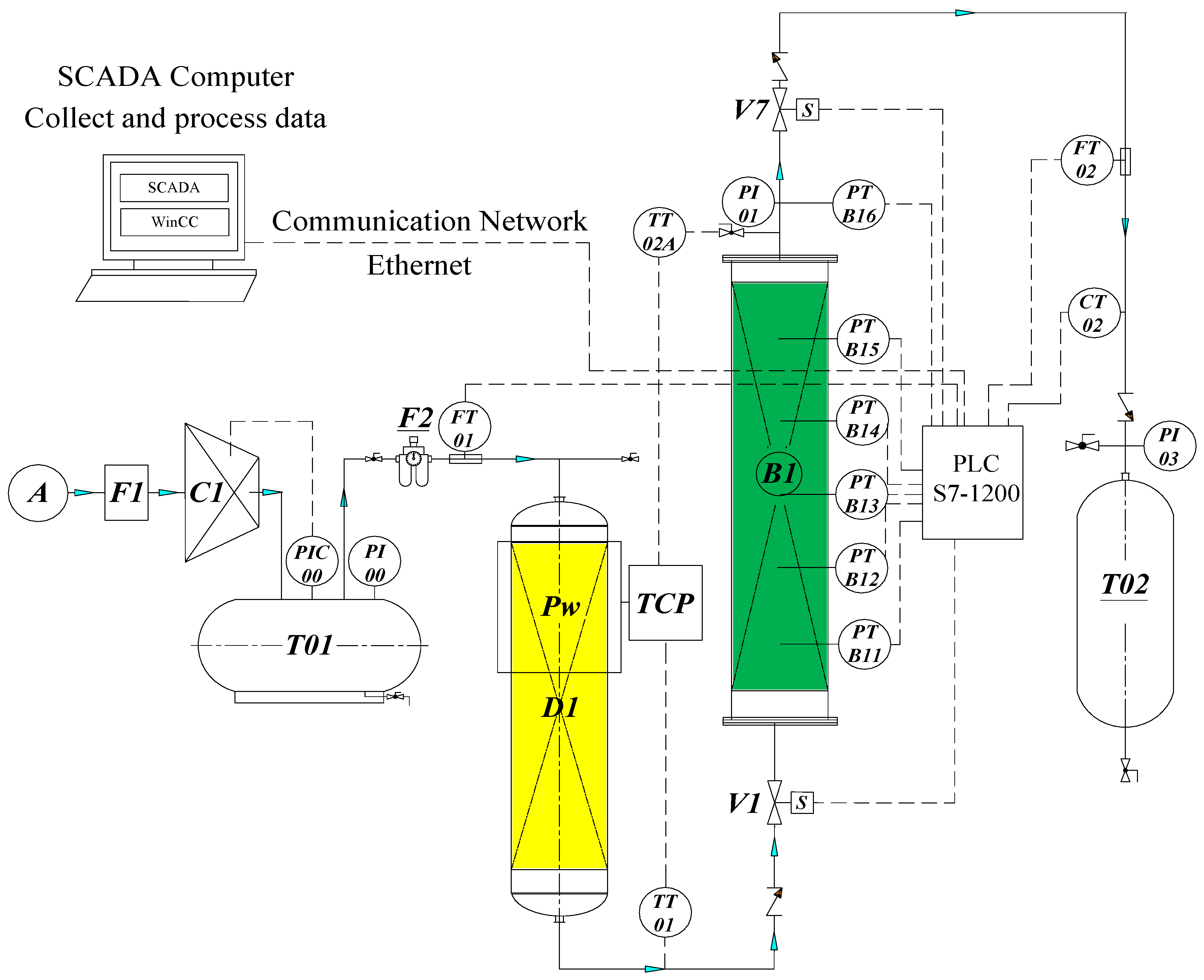
The construction of a single fixed bed experimental model is shown in Figure 2, including the following main equipment:
-
F1-primary filter; C1—piston compressor; T01—compressed air tank; D1—column of silica gel to remove water steam; F2—secondary filter;
-
B1-adsorption column (D × H = 102 × 950 mm) contains 3.5 kg CMS-240; T02-N2 gas product tank;
-
FM01—mass flow sensor to measure gas feed; FM02—mass flow sensor to measure N2 gas product with the purpose of measuring the change of flow over time and determine the amount of adsorption is an important parameter showing the adsorption capacity of the material.
-
CT02—nitrogen gas concentration sensor to measure nitrogen gas concentration output with the purpose of measuring the change in gas concentration N2 at the output of the column over time and pressurization time, adsorption time, discharge pressure time, and desorption time.
-
TT01, TT02—temperature sensors to measure the input/output temperature of a single fixed bed model to determine the temperature difference through the column.
-
PT-01/06: six pressure sensors installed according to the bed height (10 cm/1 sensor), and the purpose is to measure the pressure change according to the height of the bed and over time. These sensors are deeply inserted into the center of the bed to measure the different pressure between absorbent layers (fitting at the edge of the column will be no difference in pressure).
-
The V1 and V7 control valves (on/off; normal close), according to the settings and measurement parameters, are transmitted to S7-1200 PLC computer and recorded on the computer with control monitoring by SCADA interface programmed by WinCC V14.
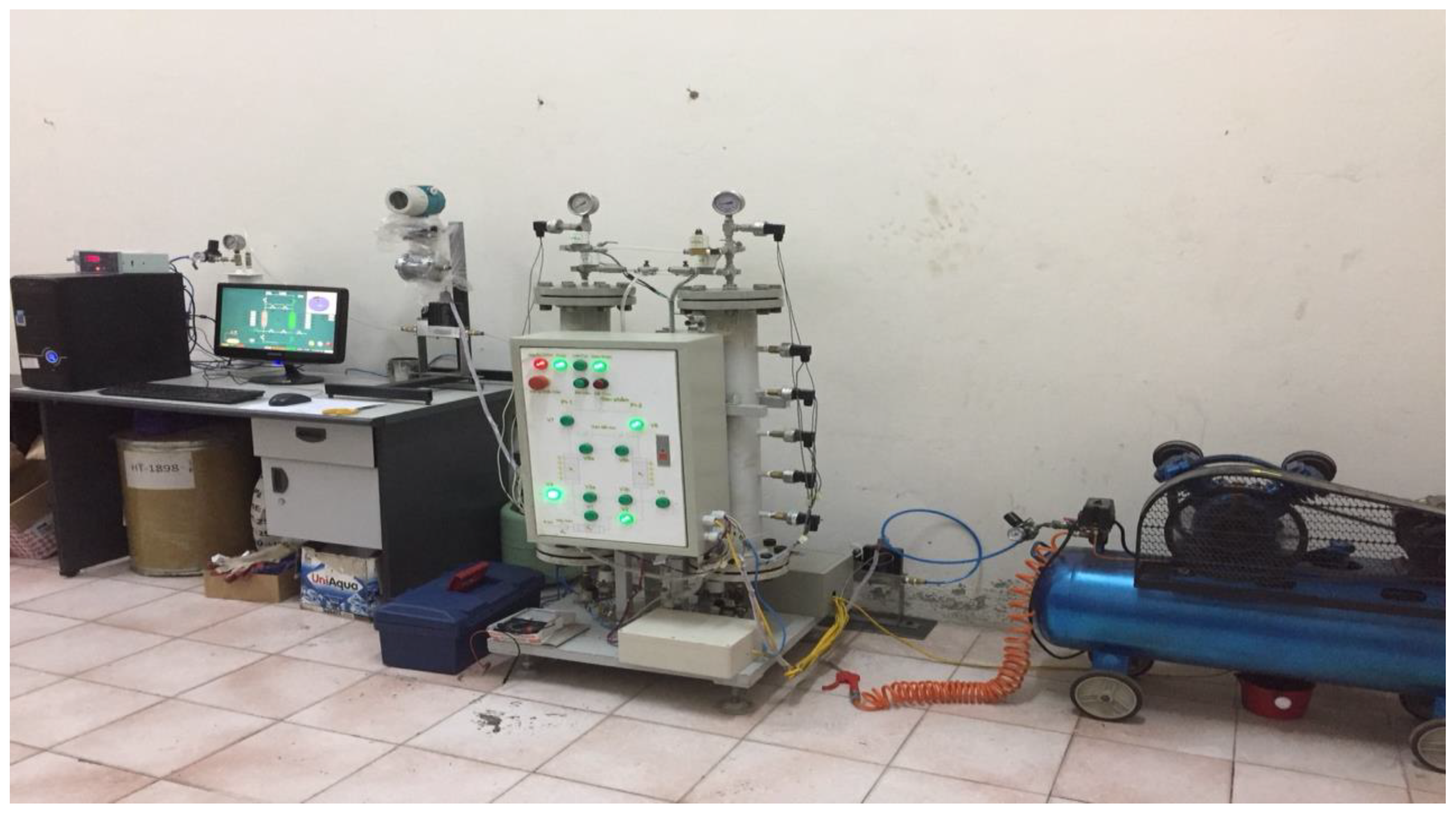
The real model of this study is shown in Figure 3. To operate this equipment as a single fixed bed model, herein, we use two valves V1 and V7, and the other valves are completely closed.

2.2. The Theoretical Basis

Research on materials and calculations, design and manufacture of laboratory equipment model, and the studied mathematical can be seen in [1,2,3,4,5,6,7,8,9,10,11,12,13,14], which are based on the balance of materials, energy, and momentum equations to find equations to change pressure over time and the height of the bed by analytic transformations. However, to study the rule of changing the technological parameters of a single bed in the equipment, it is necessary to implement the experimental plan as follows:
+
Survey 1 column with different pressures to achieve the highest concentration of N2 gas with hypothetical pressure, adsorption and desorption time to determine the real-time parameters and best working conditions of the column.
+
Determining the optimal working mode of the column.
Now we have some governing equations as follows
- First, the material equilibrium equation describing the change of the adsorbent concentration (O2) changes over time and according to the height of the column is expressed as:
C i t D L 2 C i z 2 + ( C i u ) z + ρ p ( 1 ε ε ) q i ¯ t = 0
Equation (1) can be completely solved by Matlab to simulate the change of the concentration according to the height of the column when determining the porosity parameters (ε), axial diffusion coefficient (DL) and speed apparent (u) by analysis, calculation, and experiment. But testing by experiment is difficult because it is hard to install a device that measures the exact concentration according to the height of the column.
For ideal gas (Ci = yiP/RT), Equation (1) is transformed into following forms:
D L 2 C i z 2 + y i u z + u ( y i z + y i ( 1 p P z T z ) ) y i z + y i t + y i ( 1 p P z 1 T T z ) + ( ρ p R T P ) ( 1 ε ε ) q i ¯ t = 0
P t + P u z + u P t + P T ( t ( 1 T ) u z ( 1 T ) ) 2 D L R P z z ( 1 T ) + ρ p R T ( 1 ε ε ) i = 1 n q i ¯ t = 0
Equations (2) and (3) describe the change of concentration, pressure, and temperature over time and the height of the column. Solving these equations is very complex; it is often considered that the process is isothermal (for the PSA cycle) and isometric (for the TSA cycle).
In this work, the studied column working under the PSA cycle is considered as an isothermal adsorption process. In order to simulate and verify this model, we must build an equation that describes the change of pressure over time and the height of the column. Respond to the empirical model developed to measure the pressure according to the height of the column.
Results of the analytic changes from changes in concentration to pressure changes as follows
For adsorption process we have:
p i t ( 1 + 1 ε ε K ) = ε . u . p i z + ε . D L · 2 p i z 2
For desorption process we have:
p des t ( 1 + 1 ε ε K ) = u . p des z + D des · 2 p des z 2
Equations (4) and (5) describe the change of pressure over time and according to the height of the column, which depend on the adsorption constant, porosity, axial diffusion coefficient, and speed. These parameters are determined by analysis, calculation, and experiment. This equation will be solved by Matlab. Equation (5) is one case of Equation (4) when porosity ε = 1 in the case of desorption.
- Thermal equilibrium equation is expressed as follows:
K i 2 T z 2 + ε ρ ε C p , g ( u T z + T · u z ) + ( ε t ρ g C p , g + ρ b C p , s ) T t ρ b i = 1 n ( q i ¯ t ( Δ H i ) ) + 2 h i R B i ( T T w ) = 0
Loss of heat through the column wall is defined as
ρ w C p , w A w T i , w t = 2 π R B i h i ( T T w ) 2 π R B o h o ( T w T a t m )
where Aw = π(R2B,oR2B,i).
The amount of heat expected during the adsorption process is very small, the heat generated during the adsorption process and the steaming process completely passes through the column wall. Herein, the temperature of the column will change insignificantly over time and along the height of the column, so the process is considered as an isothermal state. Then, Equations (6) and (7) are only theoretical and not experimental.
- The momentum equilibrium equation according to Eugrun’s is expressed as follows
d P d Z = a . μ . u + b . r . u . | u | ; a = 150 ( 1 ε ) 2 4 R p 2 ε 2 ; b = 1.75 ( 1 ε ) 2 R p ε
Equation (8) describes the change of pressure according to the height of the column, in addition, it depends not only on parameters such as particle size and porosity, but also it depends on the velocity of the gas flow through the column. In the theoretical calculation, it is usually taken at a constant speed however, in practice, this experimental speed can change up to 20% caused by O2 being adsorbed. So, the error between theory data and experiment data can reach 20%.
- The Langmuir–Freundlich adsorption equilibrium equation is predicted as
q i = B i q m i P i n i 1 + j = 1 n B j P j n i
in which
q m i = K 1 + K 2 · T ; B i = K 3 exp ( K 4 T ) ; n i = k 5 + k 6 T q i ¯ z = ω i ( q i q i ¯ ) ; ω i = 15 D e i r c 2 = C P r 5 ( 1 + B i P i ) 2
Equation (9) describes the adsorption load depending on the equilibrium constant, the equilibrium adsorption load and the pressure, temperature. These parameters can be determined experimentally and calculated in the case of isothermal.
In this work, the simulation of the change of pressure according to the height of the column and with the Equations (4) and (5) are established. We must determine the parameters of the model such as porosity, axial diffusion coefficient, and speed to find the solution of the above equations with the initial conditions and given boundary conditions.
For the adsorption process, Equation (4) has some fundamental conditions as follows:
+ Initial condition:
The partial pressure at (z = 0, t = 0) is p ( z , t = 0 ) = 0 .
+ Boundary conditions: According to Danckwerts standards, we have:
The partial pressure at all times in input position and output of adsorption column are: at z = z;
p ( z = 0 , t ) = { p d + D L u c p z | z = 0 , t ; 0 t t c + D L u c p z | z = 0 , t ; t t c
where pd is the partial pressure of the adsorbed material in the adsorption column at z = L;
p t | x = L = 0
where tc is the duration of the adsorption cycle.
For the desorption process, Equation (5) has some fundamental conditions as follows:
+ Initial condition:
The partial pressure at (z = 0, t = 0) is:
p ( z , t = 0 ) = p des o
+ Boundary conditions: According to Danckwerts standards, we have:
The partial pressure at all times in input position and output of adsorption column are: at z = z;
p ( z = 0 , t ) = { p des d + D L u des p des z | z = 0 , t ; 0 t t c p des c ; t t c
where pd is the partial pressure of the adsorbed material in the adsorption column at x = L;
p des t | z = L = 0
where tc is the duration of the adsorption cycle.
In this study, we will not simulate the adsorption process. Because when the simulation time is set, this process is very similar to the adsorption process.

3. Calculation and Simulation Results

Calculation to determines the porosity of the column [16,17,18,19] includes some steps as follows
+ Determining bulk density ρ b = 0.676 g/cm3, particle density ρ p = 0.78 g/cm3 and solid density ρ s = 2.174 g/cm3 by means of volume, mass weighing, and pycnometer.
The porosity of the column is determined in the following Table 1.
+ Determining the air velocity through the column [16,17,18,19] can be expressed as:
u c = V k k ε t π D 2 4
When the total pressure reaches the critical pressure, the free step of the gas molecule is approximately the capillary size. Diffusion follows both the Knusen diffusion and molecular diffusion mechanisms:
+
Diffuse in transition zone [16,17,18,19] is:
1 D L = 1 D A B + 1 D k
+
Molecular diffusion [16,17,18,19] is:
D A B = 0.00158 T 3 / 2 ( 1 M A + 1 M B ) P · σ A B 2 Ω A B 1 / 2
+
Flow diffusion (Knusen) [16,17,18,19] is:
D K = 9700 · R p · ( T M ) 1 / 2
From (11)–(13) we determine the basic parameters of the models (4) and (5) following pressure and temperature:
From the results from Table 1 and Table 2 we can simulate adsorption column according to the change of partial pressure of adsorbed material over time and in column height in case of unstable working column V1, V2 are open, the installation time is 460 s to observe the maximum capacity of the column at a pressure from 1 bar to 8 bar. In this paper we only give results at pressures of 5 bar, 5.5 bar and 8 bar for discussion.
+ Simulation (4):
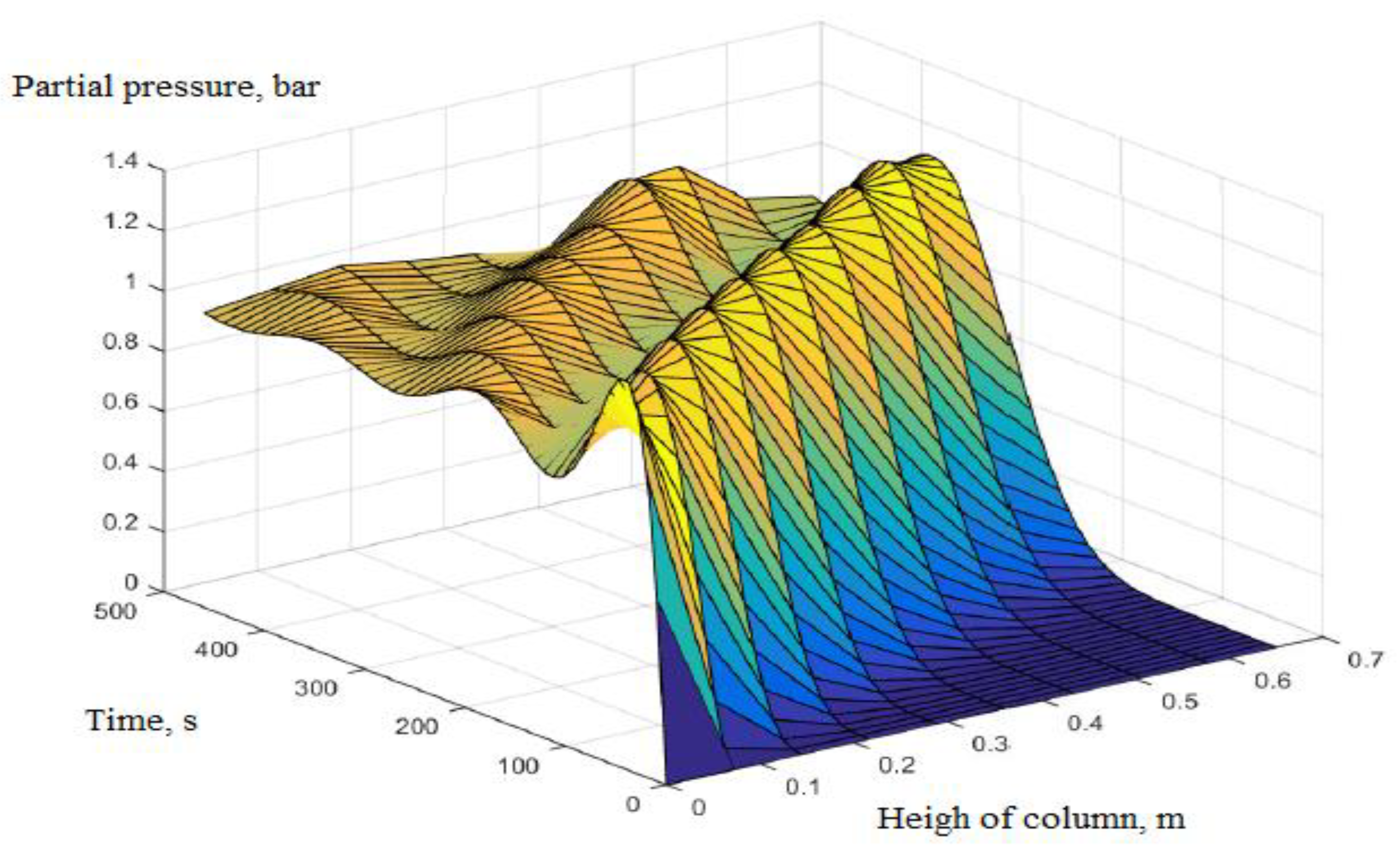
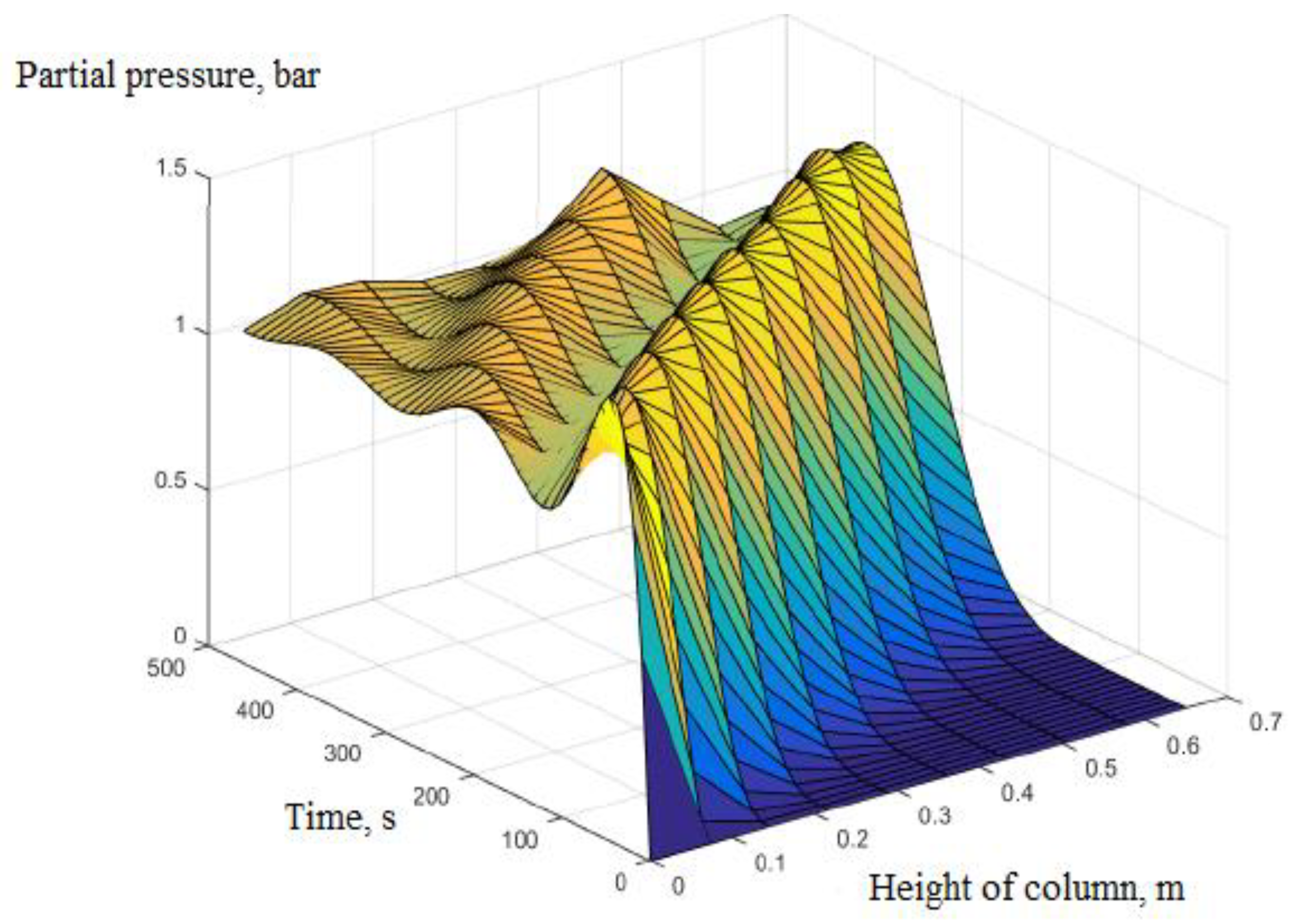
By simulating results at pressure of 5 bar by Matlab with initial conditions and boundary conditions above, we have the partial pressure of O2 initially of 1 bar (corresponding to 20% of the mole of the initial 5 bar gas mixture) with t = 460 s:
Figure 4 shows that the partial pressure of the adsorbent (O2) decreases over time and according to height of the column corresponding to the gradual reduction of the adsorbed concentration (O2). This means that the concentration of N2 increases gradually at the output of the column.
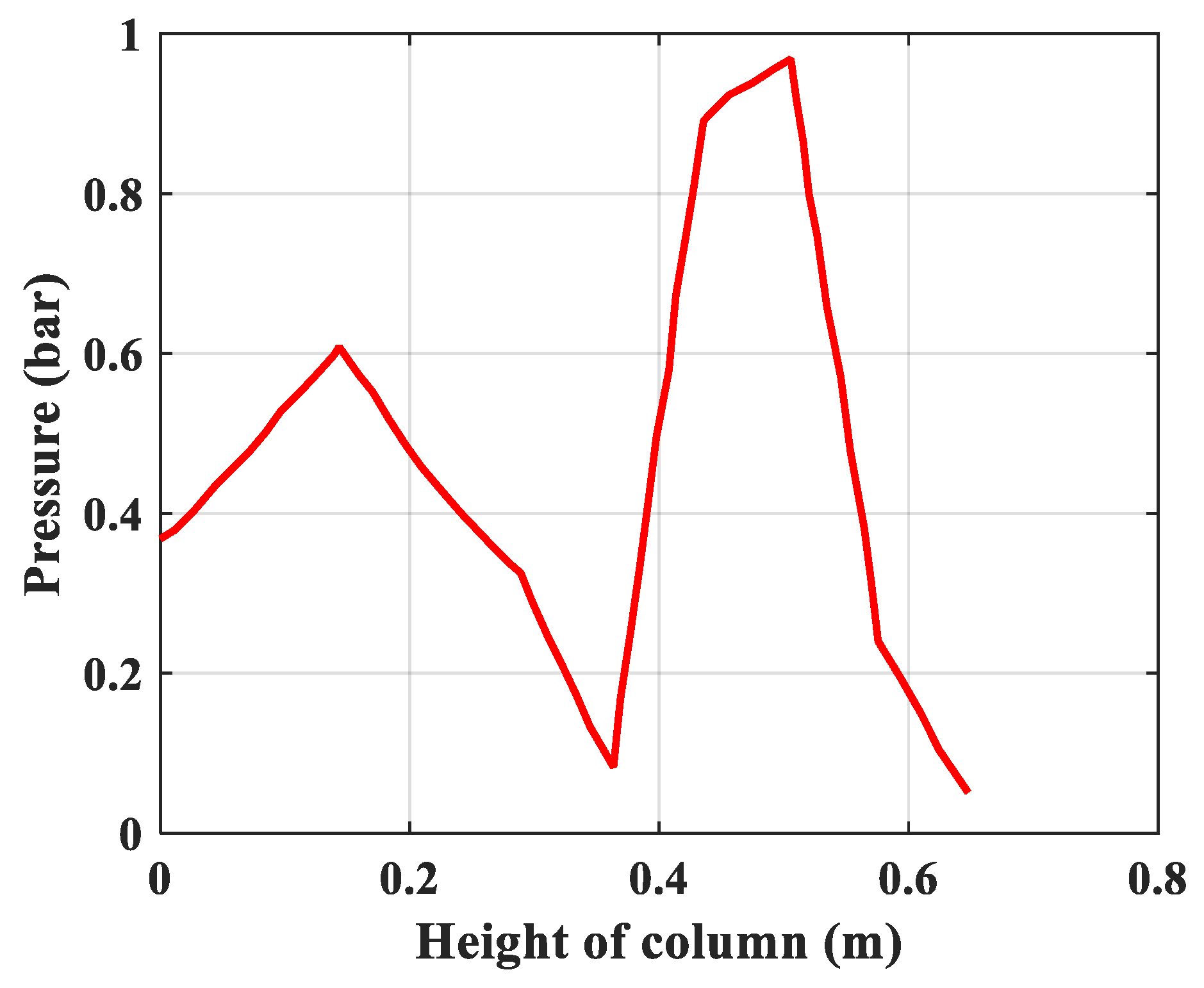
The following Figure 5 and Figure 6 are the 2D sections of Figure 4 at the time t = 60 s and at the height of column h = 0.65 m.
Figure 5 shows that the partial pressure 0.91 bar of the adsorbent is reduced to the lowest at 0.65 m height (the end of the column), and the corresponding pressure loss through the column is approximately 0.1 bar.
Figure 6 shows that the partial pressure starts to increase only after about 30 s. It means that at that time the column is saturated, the adsorption capacity decreases. Pressure at 460 s time decreases by approximately 0.1 bar.
Next, by simulation results at maximum pressure of 5.5 barby MATLAB with initial conditions and boundary conditions above, we have the partial pressure of O2 initially of 1.1 bar (corresponding to 20% of the mole of the initial 8 bar gas mixture) with t = 460 s.
The following Figures 8 and 9 are the 2D sections of Figure 7 at the time t = 60 s and at the height of column h = 0.65 m.
Similar to the case of 5 bar, but the partial pressure decreases with time and the column height is faster, Figure 7 almost likes Figure 4.
Figure 8 shows that the partial pressure of the adsorbent (O2) decreases signifficantly at the output. This may be the optimal working point of the model (4). Drop pressure through column is 0.148 bar.
Figure 9 shows that partial pressure starts to increase after about 25 s. It means that when the column is saturated, the adsorption capacity decreases. The pressure at 460 s has increased by approximately 0 bar. That means the partial pressure (O2) at the output of the column is (O2) air feed. This confirms again that the pressure of 5.5 bar is the optimal value. Adsorption time is about 25 s.
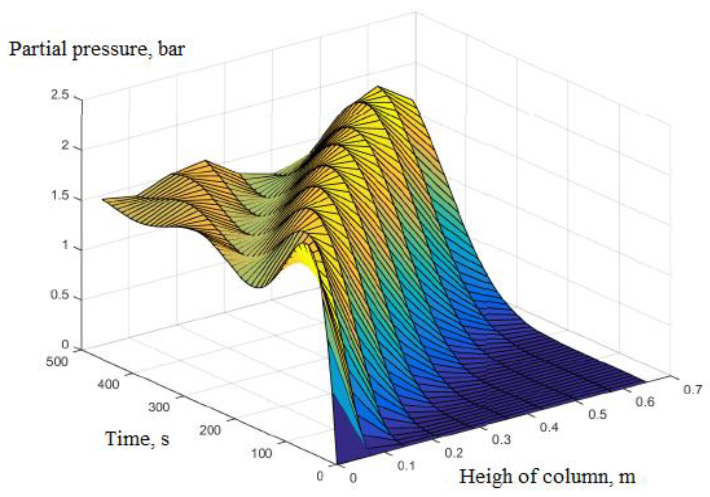
For simulation results (by Matlab) at maximum pressure of 8 bar with initial conditions and boundary conditions, the partial pressure of initial O2 gas is 1.6 bar (corresponding to 20% of the mole of the initial 8 bar gas mixture) at t = 460 s.
Similar to the case of 5 bar, but the partial pressure decreases with time and the column height is faster, Figure 10 indicates a larger slope.
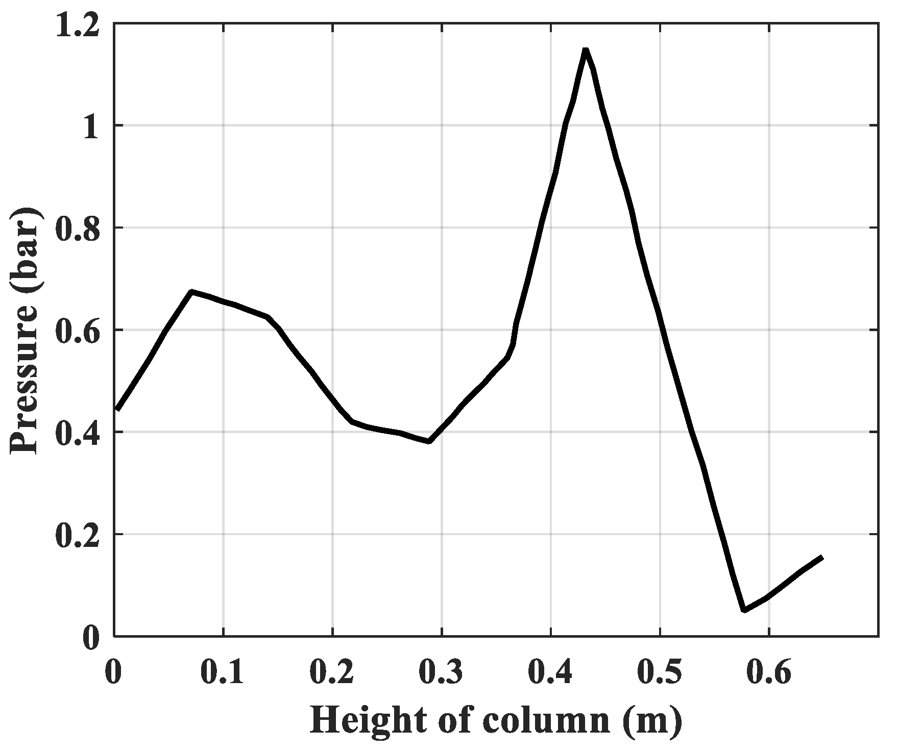
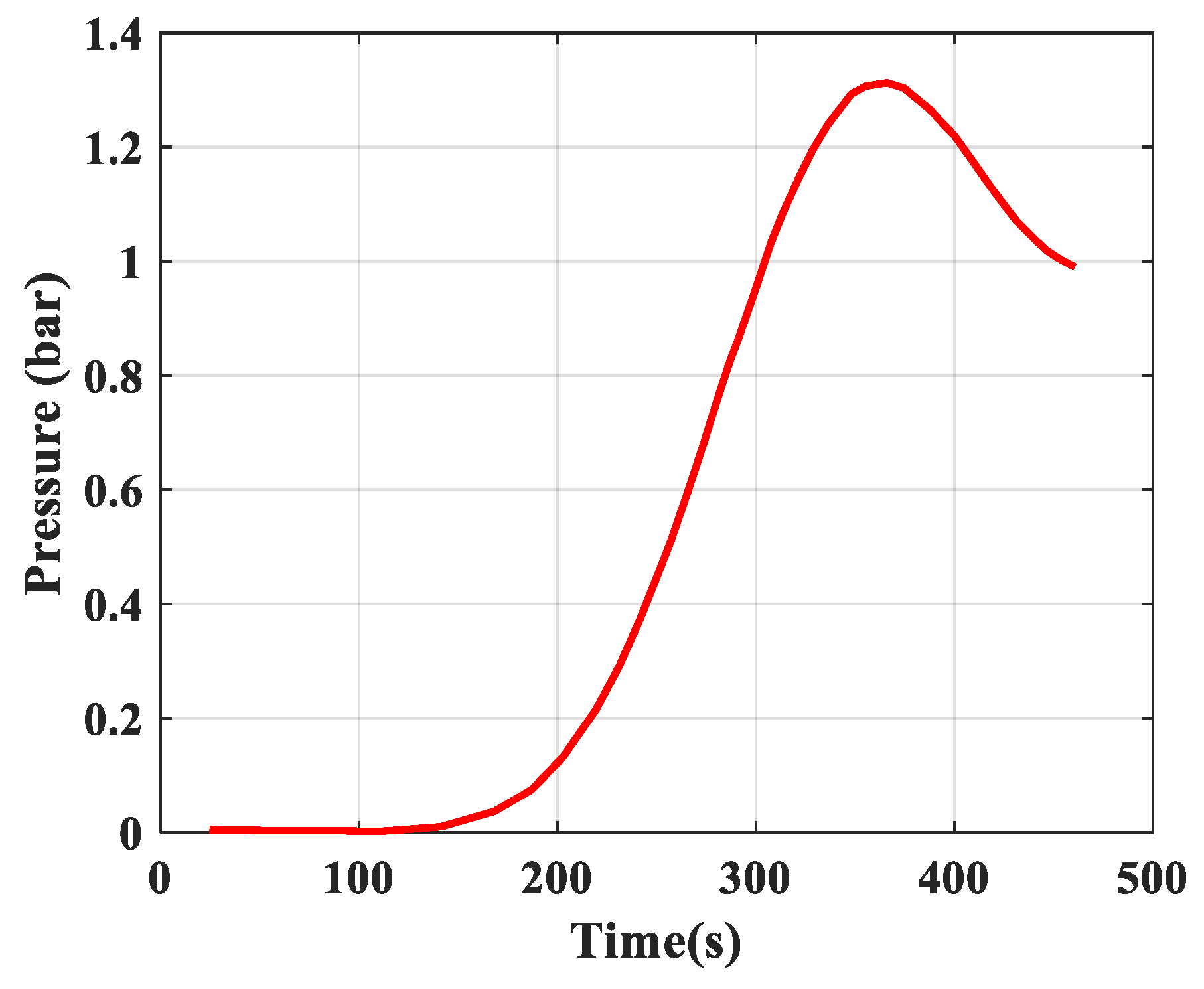
The following Figure 11 and Figure 12 are the 2D sections of Figure 10 at the time t = 60 s and at the height of column h = 0.65 m.
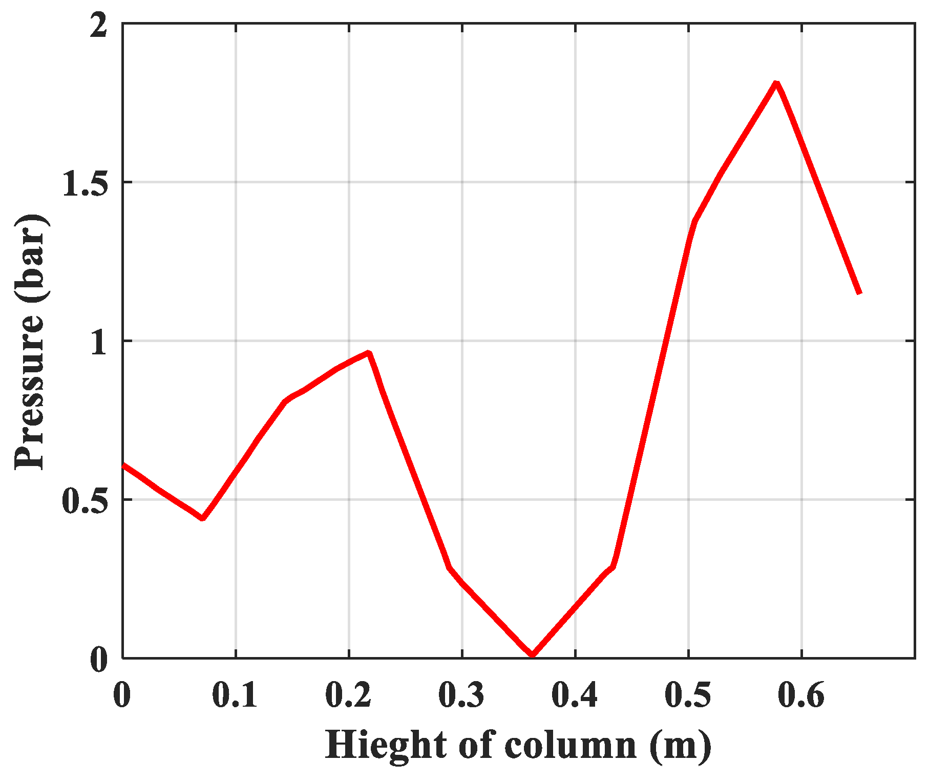
Figure 11 shows that the partial pressure 1.4 bar of the adsorbent is reduced to the lowest at 0.36 m of height (the middle of the column), and the corresponding pressure loss through the column is approximately 0.2 bar. At the end of the column, the partial pressure (O2) is increased by desorption.
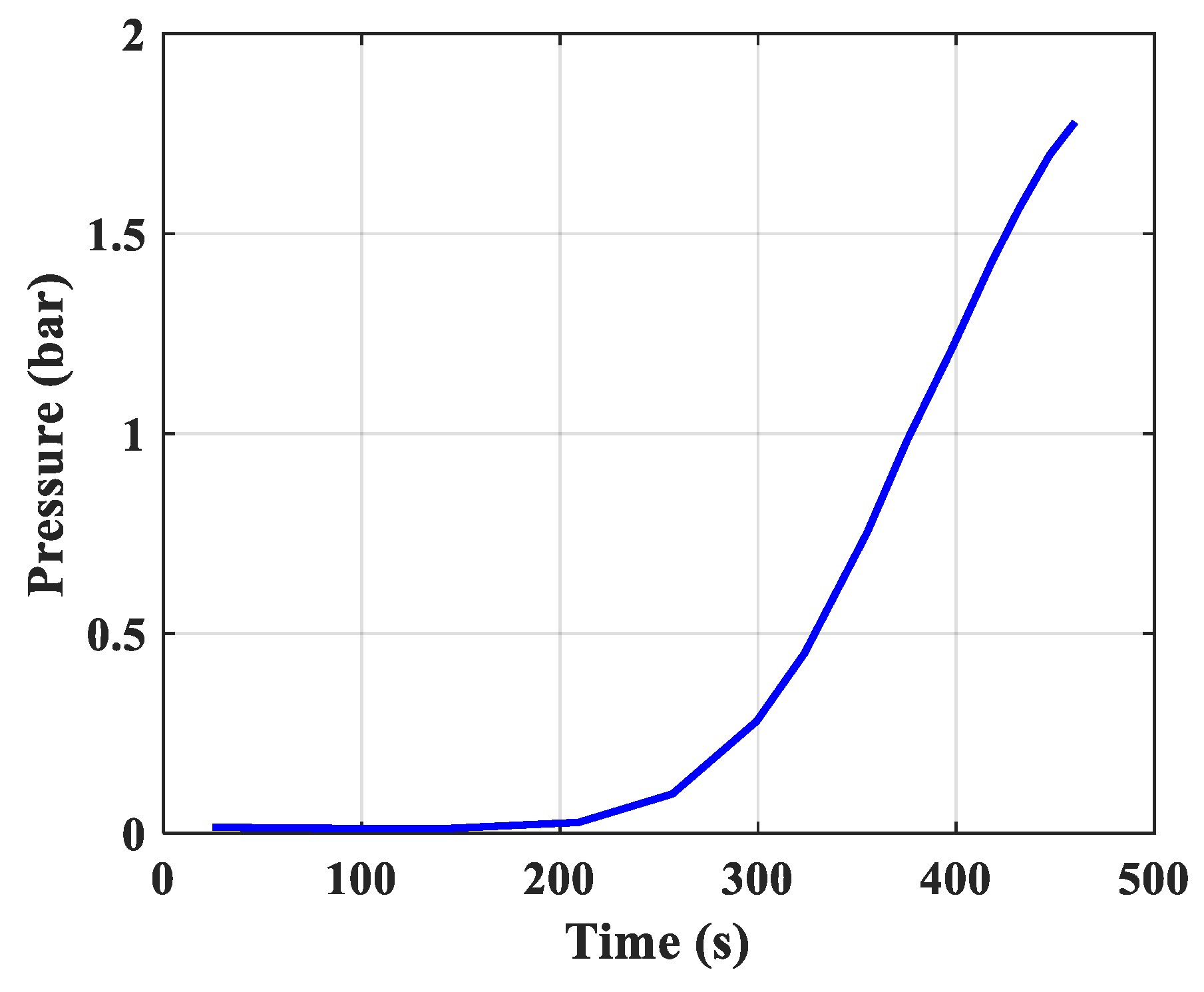
Figure 12 shows that partial pressure starts to increase after about 25 s. It also means that when the column is saturated, the adsorption capacity decreases. The pressure has increased by approximately 0.2 bar at the time t = 460 s. That means the partial pressure (O2) at the output of the column includes (O2) air feed and (O2) desorption.
Drop pressure adsorption and desorption processes are expressed as follow
Δ P h p H = 150 · μ ( 1 ε t ) 2 ( d p ψ ) 2 ε t 3 ν h p + 1.75 · ( 1 ε t ) ρ g ε t 3 ( d p ψ ) ν h p 2
Drop pressure through the particle layer is expressed as
Δ P C M S ( t a ) = λ h 2 · H C M S d o · ρ · ν t a 2 2
Total drop pressure through a bed is defined as
Δ P T ( h p ) = λ h 2 · H C M S d o · ρ · ν t a 2 2 + [ 150 · μ ( 1 ε t ) 2 ( d p ψ ) 2 ε t 3 ν h p + 1.75 · ( 1 ε t ) ρ g ε t 3 ( d p ψ ) ν h p 2 ] · H
The calculated results of drop pressure at 5 bar, 5.5 bar, and 8 bar are, respectively, 0.2 bar, 0.16 bar, and 0.14 bar. This calculation result has a slight difference compared with the simulation. Both of these results are very good data to reference with the experimental results given below.

4. Experiment Results and Discussions

To verify the calculation and simulation results above, we conduct the experiment set up according to Figure 2 (the data Table 3 below). The investigation of a single fixed bed from 1 bar to 8 bar is carried out and we assume an adsorption time of 60 s and a desorption time of 400 s to observe the real adsorption and desorption process on real-time graphs and determine the adsorption and desorption time.
According to the principle of technological parameters in the operation such as temperature, pressure, flow, and gas concentration N2 we can observe the rule when surveying the column at 1 bar pressure. The data resolution is drawn on the graph with higher quality.
+
Temperature: the temperature is considered constant
+
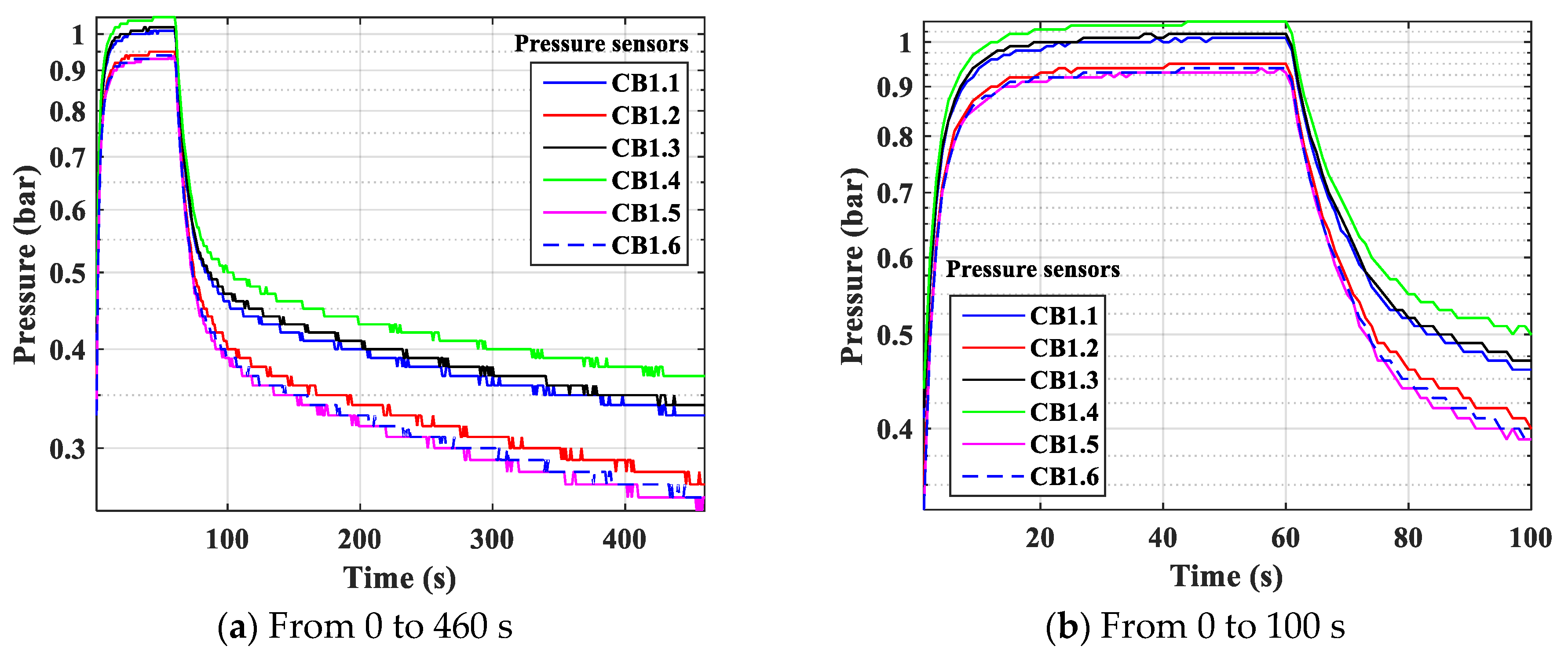
Pressure: The pressure changes over time and according to the height of the column. The experimental results of the pressure changes over time and the pressure distribution of the column height (with 6 sensors CB-1.1 to CB-1.6) are clearly seen in Figure 13 when surveying one column according to setup mode in Table 3 at 1 bar pressure. At the higher pressures, the lower resolution makes it more difficult to see.
From Figure 13, we see the rule of pressure change in a column over time an adsorption cycle set. One column adsorption cycle includes pressurization time, adsorption time, pressure release time and desorption time. Observing the above graphs shows the form of the pressure line: straight-line pressurization phase with slope coefficient >0 pressure increased rapidly over time, the adsorption phase of the convex curve type slightly increased to constant, straight-line pressure release phase with slope coefficient <0 pressure rapid decrease over time, the desorption phase form concave curve pressure decreases slowly under low pressure and desorption along time. From this figure, we can determine the drop pressure through the column. Figure 13 shows the two-dimensional (2D) section of the change and distribution of the total pressure over time and the height of the column; it is similar to the three-dimensional (3D) simulation of partial pressure presented in Figure 4, Figure 7 and Figure 10, which are processed by MATLAB according to Equation (4).
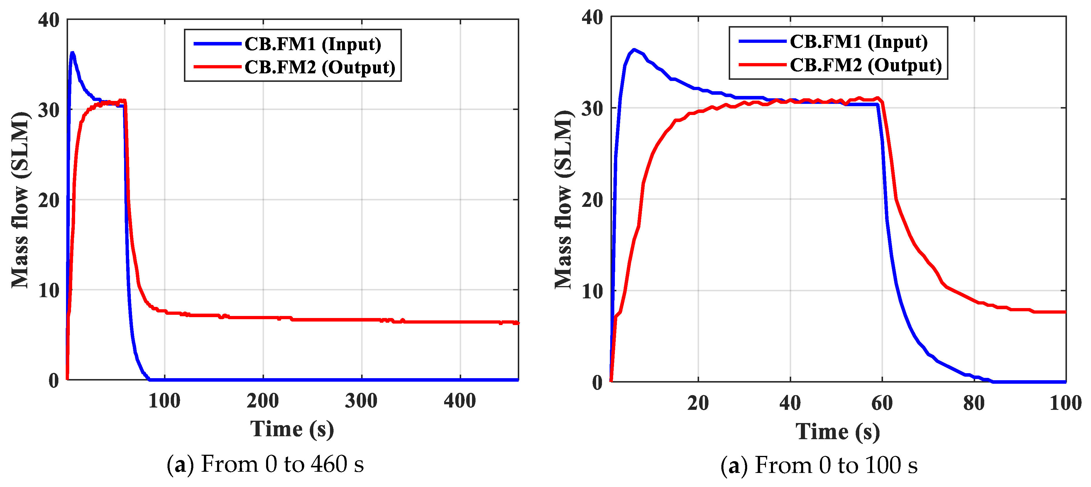
+ Mass flow input/output: Experimental results of input/output flow stream are obtained by 02 sensors FM1, FM2 (slm) referring to standard conditions. The experimental results at 1 bar pressure are observed in Figure 14 (the blue line is the flow from FM1, the red line is the flow from FM2). The difference between the two lines can determine the adsorption and desorption processes of the column
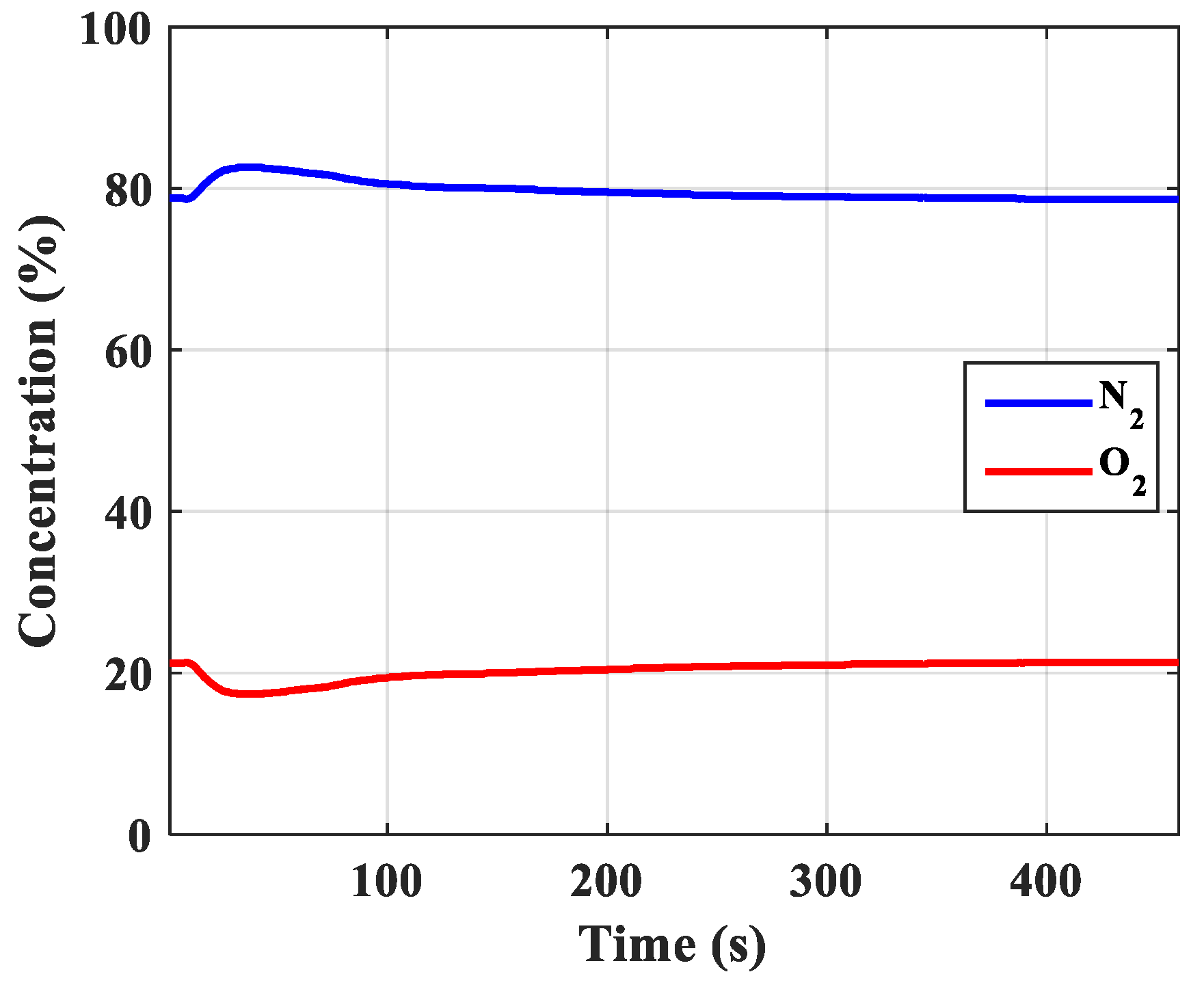
Figure 15, we can see the changing law N2 gas and O2 gas concentration at the output of the column over time, here we can determine the pressurization time, adsorption time, pressure release time, desorption time, and the change in concentration according to pressure until saturation. From this image, we can determine the amount of adsorption.
+ Concentration of gas N2 at the output of the column: Experimental results of concentration N2 and O2 obtained by CT-02 sensor are observed in Figure 15 at 1 bar pressure. The highest concentration of N2 reached 82.6%.
Figure 15 shows clearly that the concentration of N2 gas changes over time at the output of the column. The time of hypertension is the time when the concentration does not change, the adsorption time is the time of increasing concentration of N2 gas, the pressure drop time is constant high concentration-time (this is the time to take reasonable products), and the time of sorption release is the time that N2 concentration decreases.
Combining Figure 13, Figure 14 and Figure 15, we can completely determine the parameters of time, amount of adsorbed and pressure loss through the column. The following Table 4 presents experimental results of column survey from 1 bar to 8 bar. However, the 5 bar column has shown saturation.
Table 4 is clearly shown in Figures 17–20 below, showing the relationship and interplay between the technological parameters and workability of the column. Survey data to 8 bar demonstrate saturation of the column.
Figure 16, Figure 17, Figure 18, Figure 19 and Figure 20 are experimental results of one column from 1 bar to 8 bar pressure. We can observe that, at 5 bar pressure, the column reaches saturation state.
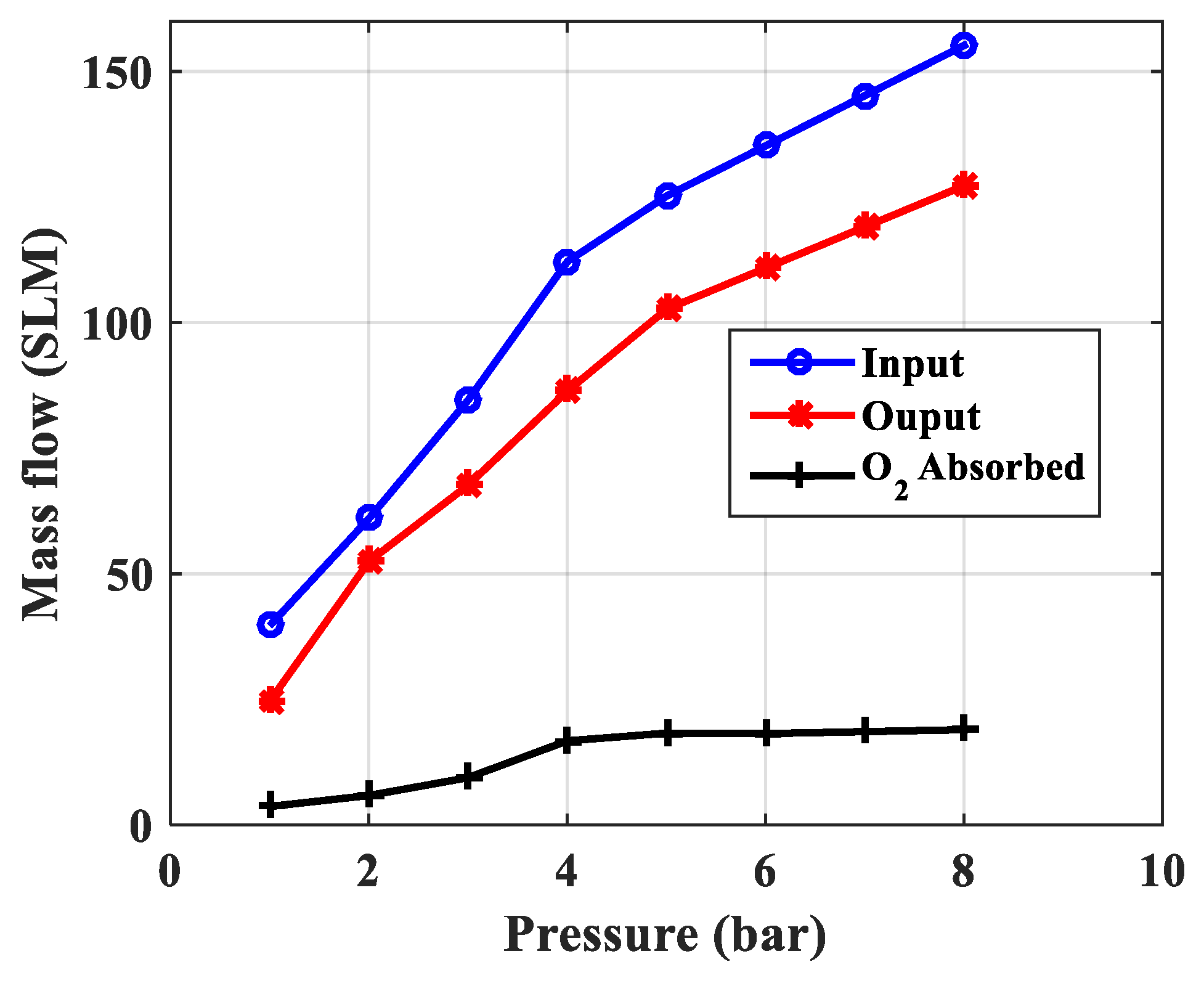
Figure 16 presents the flow measurement of input/output streams of the column from 1 bar to 8 bar pressure, and the black line is the amount of adsorbed O2.
Figure 16 shows that when the pressure increases, the inlet/outlet airflow also increases, the amount of adsorbent increases to a certain limit at 5 bar pressure.
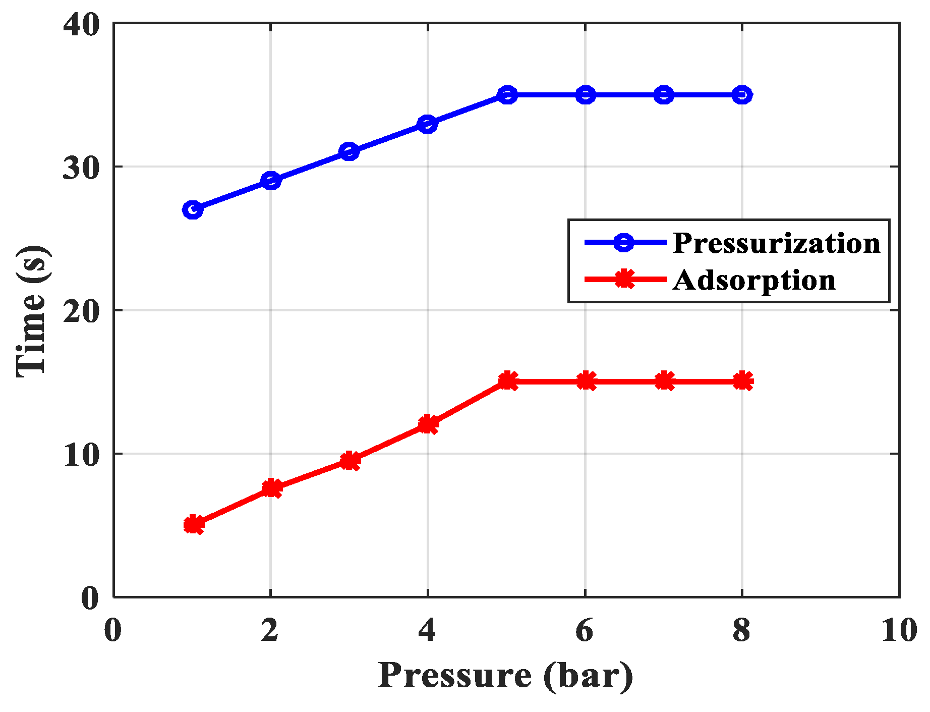
Figure 17 shows the experimental results of the boosting time and adsorption time from Figure 13, Figure 14 and Figure 15 (1 bar to 8bar pressure) according to real changes (when setting the running time is 460 s).
Figure 17 shows that when the pressure increases, pressurization time and adsorption time also increased to the limit at 5 bar pressure.
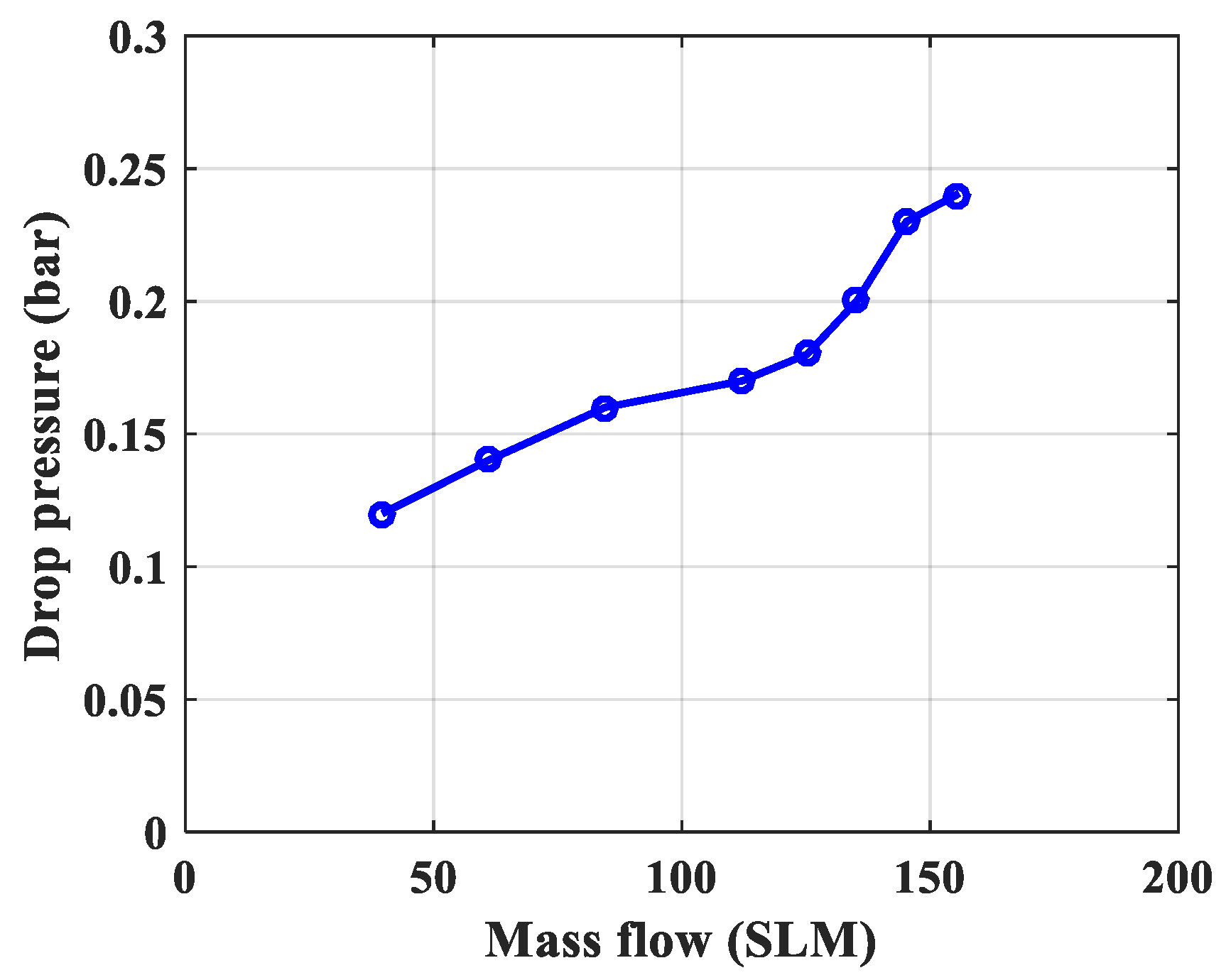
Figure 18 presents the experimental data of the drop pressure changing over time and according to the height of the column, which is shown in Figure 13. This result is determined by the maximum difference between the sensors CB-1.1 and CB-1.6.
Figure 18 shows that when the mass flow increases, drop pressure also increased.
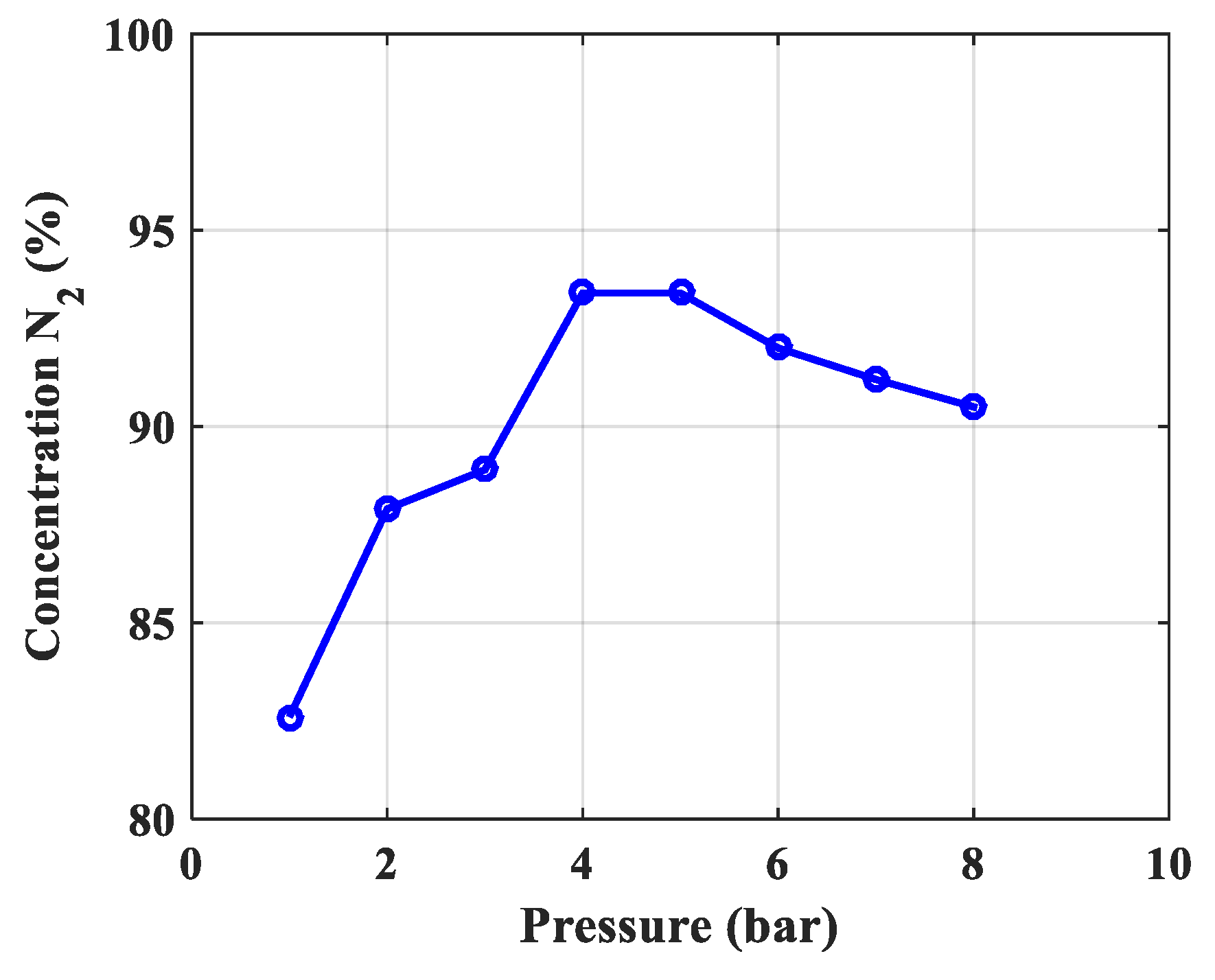
Figure 19 presents the highest concentration of N2 gas at the output of the column from 1 bar to 8 bar pressure.
Figure 19 shows that when the pressure increases, concentration N2 gas at output also increased to 5 bar, after decreasing due to the saturation.
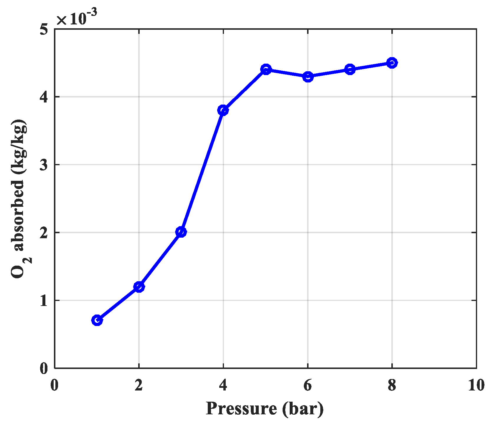
Figure 20 is the experimental data of absorbed O2 by determining the difference between input and output flow with sensors FM1 and FM2 from 1 bar to 8 bar pressure.
Figure 20 shows that, when the pressure increases, the amount of O2 gas absorbed also increased to 5 bar, remaining so as pressure increases further due to the saturation.
From Figure 16, Figure 17, Figure 18, Figure 19 and Figure 20, we see the optimal working point of the column at a pressure of 5 bar, the concentration N2 gas product of the column reaches the highest of 93.4%. The maximum amount of adsorbent 18.26 L/minute is equivalent to 0.0044 kg O2/1 kg CMS-240.The maximum adsorption time of O2 gas is 35 s. The maximum pressurization is 15 s.
Finally, the compare simulation and experimental results are listed in Table 5.

5. Conclusions

Based on the proposed theory and simulation and experimental results, we have some conclusions to highlight as follows. Calculating and simulating adsorption columns is a very difficult task to deal with, however, with a suitable theory and mathematical tools, such as the help of computer software, we can simulate the partial pressure change of the adsorbed substance over time and in the direction height of the column. The partial pressure of the adsorbed material decreases both over time and the height of the column. The optimum working pressure of the column is 5.5 bar and adsorption time is 25 s. This simulation result is nearly accurate and has a margin of about 20% due to the rate of change, which in the simulation we calculated the speed as constant at the time of the column input. Drop pressure in this process is 0.148 bar. From the experimental research results, we understand the adsorption column uses a CMS-240 carbon molecular sieve material to separate N2 from air working in environmental, isothermal, working regime stability (pressure change over time) can separate N2 gas to reach a maximum concentration of 93%. Total pressure changes over time and decreases with column height. The optimal working mode at a pressure of 5 bar with adsorption time parameters is determined in Figure 20. Experimental results also show the mutual influence of technological parameters and the adsorption capacity of materials and columns.
The results of simulated and experimental research are very reliable on the basis of practical models and perfect laboratory equipment. The research methods and results are a solid basis for studying two columns and equipment according to the PSA cycle.

Author Contributions

Investigation, P.V.C., Software, H.N.N., V.D.T.; Methodology, P.V.C., H.N.N., N.T.H.; Visualization, V.D.T., T.-Y.N.; Formal Analysis, N.T.A., P.V.C. and T.-Y.N.; Writing—original draft, P.V.C., V.D.T., T.-Y.N.; Writing—review & editing, H.-N.N., D.V.T.

Funding

This research was funded by Institute of Technology—General Department of Defense Industry grant number 100.02-2019.10.

Conflicts of Interest

The authors declare no conflict of interest.

Abbreviations

SymbolUnitMeaning
DL[cm2·s−1]Vertical dispersion coefficient (adsorption column)
ki[1·s−1]Mass transfer factor of the component i
Ki[-]Equilibrium constant of the component i
Z[m]Distance along the column (from the beginning of the column to the end of the column)
ΔP[bar]Drop pressure of the column
qi[g·g−1]The amount of gas absorbed in the adsorbent of the component i
q*i[g·g−1]The amount of gas adsorbed in the material adsorbing when equilibrium of the component i
rp[µm]Particle radius
ε t [ m 3 v o i d m 3 ] Total porosity (porosity inside and between particles)
P[mmHg, KG/cm2]Pressure
V[m3]Volume
T[K]Absolute temperature
Ci[mole/cm3]The concentration of component i in the gas mixture
t[s]Time
U[m/s]velocity inside the column
ρp[g/cm3]Particle density of adsorbent
KL[J/cm·s·K]Thermal conductivity coefficient along the axis
Tw[K]The temperature of the column wall
Tatm[K]Temperature of the surrounding environment
ρg[g/cm3]Density of gas
ρb[g/cm3]Bulk density of adsorbent
ρw[g/cm3]The density of material column wall
Cpg[J/g·K]Specific heat capacity of gas
Cps[J/g·K]Specific heat capacity of adsorbent
Cpw[J/g·K]Specific heat capacity of material column wall
−ΔH[J/mol]Heat effect of adsorption process
hi[J/cm2·K·s]Internal heating factor
ho[J/cm2·K·s]External heating factor
RBi[cm]Inner radius of the column
RBo[cm]Outside radius of the column
Aw[cm2]Cross-sectional area of the wall
B[kPa−1]Langmuir equation parameters expanded
qm[mol/kg]The equilibrium parameter for the extended Langmuir equation
Pi[kPa]Pressure of the component i
K-The coefficient of Langmuir equation extends

References

  1. Kulkarami, S.J. Pressure Swing Adsorption: A Summary on Investigation in Recent Past. Int. J. Res. Rev. 2016, 3, 46–49. [Google Scholar]
  2. Ashkan, M.; Masoud, M. Simulation of a Single Bed Pressure Swing Adsorption for Producing Nitrogen. In Proceedings of the International Conference on Chemical, Biological and Environmental Sciences, Bangkok, Thailand, 23–24 December 2011. [Google Scholar]
  3. Smith, A.R.; Klosek, K. A review of air separation technologies and their integration with energy conversion processes. Fuel Process. Technol. 2011, 70, 115–134. [Google Scholar] [CrossRef]
  4. Carlos Grande, A. Advance in Pressure Swing Adsorption for Gas Separation. ISRN Chem. Eng. 2012, 2012, 982934. [Google Scholar]
  5. Snehal Patel, V.; Patel, J.M. Separation of High Purity Nitrogen from Air by Pressure Swing Adsorption on Carbon Molecular Sieve. Int. J. Eng. Res. Technol. 2014, 3, 450–454. [Google Scholar]
  6. Delavar, M.; Nabian, N. An investigation on the Oxygen and Nitrogen separation from air using carbonaceous adsorbents. J. Eng. Sci. Technol. 2015, 10, 1394–1403. [Google Scholar]
  7. Roy Chowdhury, D.; Sarkar, S.C. Application of Pressure Swing Adsorption Cycle in the quest of production of Oxygen and Nitrogen. Int. J. Eng. Sci. Innov. Technol. 2016, 5, 64–69. [Google Scholar]
  8. Shafeeyan, M.S.; Daud, W.M.A.W.; Shamiri, A. A review of mathematical modeling of fixed-bed columns for carbon dioxide adsorption. Chem. Eng. Res. Des. 2014, 92, 961–988. [Google Scholar] [CrossRef]
  9. Zhe, X.U. Mathematically modeling fixed-bed adsorption in aqueous systems. Appl. Phys. Eng. 2013, 3, 155–176. [Google Scholar]
  10. Ehsan, J.S.; Masoud, M. Pilot-Scale Experiments for Nitrogen Separation from Air by Pressure Swing Adsorption. S. Afr. J. Chem. Eng. 2014, 19, 42–56. [Google Scholar]
  11. Shokrooi, E.J.; Motlaghian, S.M.A.M. A robust and user friendly sofware (TB-PSA-SS) for numberical simulation of two-bed pressure swing adsorption processes. Pet. Coal 2015, 57, 13–18. [Google Scholar]
  12. Furtat, I.B. Mathematical model of the process of adsorption. Models and modeling. ASTU Bull. 2008, 42, 24–30. [Google Scholar]
  13. Akulinin, E.I.; Butler, D.S.; Dvoretsky, S.I.; Simanenkov, A.A. Mathematical Modeling of the Process of Oxygen Enrichment with Air in the Installation of Short-Cycle Adsorption. TSTU Bull. 2009, 2, 341–355. [Google Scholar]
  14. Akulinin, E.I.; Dvoretsky, D.S.; Dvoretsky, S.I. Investigation of Heat and Mass Transfer Processes for Enriching Air with Oxygen with Hydrogen through Short-Cycle Adsorption Method. TSTU Bull. 2016, 22, 411–419. [Google Scholar]
  15. Kevin Wood, R.; Liu, Y.A.; Yu, Y. Design, Simulation and Optimization of Adsorption and Chromatographic Separation: A Hand-on Approach, 1st ed.; Wiley-VCH Verlag GmbH and Co. KGaA: Hoboken, NJ, USA, 2018. [Google Scholar]
  16. Suzuki, M. Adsorption Engineering; University of Tokyo: Tokyo, Japan, 1990. [Google Scholar]
  17. Ruthven, D.M. Principles of Adsorption and Adsorption Process; Wiley-VCH Publishers: New York, NY, USA, 1984. [Google Scholar]
  18. Douglas Ruthven, M.; Shamsuzzanman, F.; Kent Knaebel, S. Pressure Swing Adsorption; Wiley-VCH Publishers: New York, NY, USA, 1994. [Google Scholar]
  19. Seader, J.D.; Ernest Heney, J.; Keith Roper, D. Separation Process Principles Chemical and Biochemical Operations; John Wiley and Sons, Inc.: Hoboken, NJ, USA, 2011. [Google Scholar]
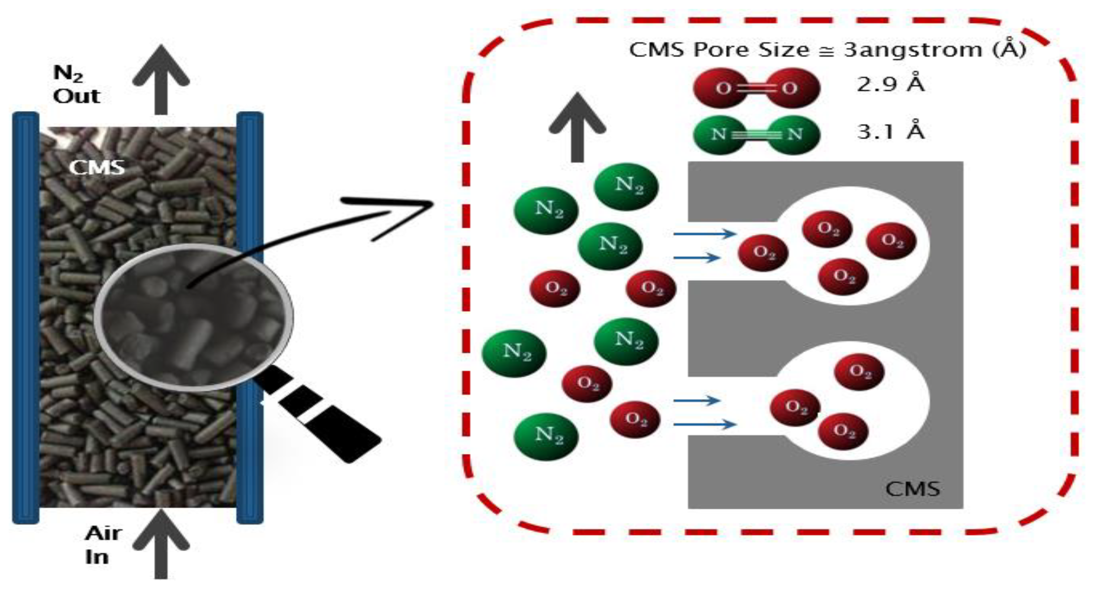
Figure 1. Selective adsorption mechanism of CMS material.
Processes 07 00654 g001
Figure 2. A single bed model.
Processes 07 00654 g002
Figure 3. The experimental equipment system.
Processes 07 00654 g003
Figure 4. The result of partial pressure (O2) following over time and height of column at 5 bar.
Processes 07 00654 g004
Figure 5. The result of partial pressure (O2) following height of column at 5 bar.
Processes 07 00654 g005
Figure 6. The result of partial pressure (O2) following over time at 5 bar.
Processes 07 00654 g006
Figure 7. The result of partial pressure (O2) following over time and height of column at 5.5 bar.
Processes 07 00654 g007
Figure 8. The result of partial pressure (O2) following height of column at 5.5 bar.
Processes 07 00654 g008
Figure 9. The result of partial pressure (O2) following over time at 5.5 bar.
Processes 07 00654 g009
Figure 10. The result of partial pressure (O2) following over time and height of column at 8 bar.
Processes 07 00654 g010
Figure 11. The result of partial pressure (O2) following height of column at 8 bar.
Processes 07 00654 g011
Figure 12. The result of partial pressure (O2) following over time at 8 bar.
Processes 07 00654 g012
Figure 13. Pressure over time and heigh of a single fixed bed (see Figure 2).
Processes 07 00654 g013
Figure 14. Mass flow input/output of a single fixed bed (see Figure 2).
Processes 07 00654 g014
Figure 15. Concentration of gas N2 at the output of a single fixed bed (see Figure 2).
Processes 07 00654 g015
Figure 16. The amount of adsorbed material depends on the adsorption pressure.
Processes 07 00654 g016
Figure 17. Adsorption time depends on adsorption pressure.
Processes 07 00654 g017
Figure 18. Drop pressure depends on incoming air flow input.
Processes 07 00654 g018
Figure 19. The dependence of N2 concentration on adsorption pressure.
Processes 07 00654 g019
Figure 20. The amount of O2 gas absorbed depends on the pressure.
Processes 07 00654 g020
Table 1. Results of calculation porosity of a single fixed bed.
1Porosity outside or between particlesεim3/m3 ε i = V X V T = 1 ρ b ρ p 0.1326
2Porosity in the grainεpm3/m3 ε p = V p V T V X = 1 ρ b ρ s 0.556
3Total porosityεtm3/m3 ε t = V p + V X V T ε t = ε i + ε p ( 1 ε i ) 0.615
Table 2. Results of calculation parameters of a single fixed bed model at different pressure.
OrderPressurePbar12345678
1Gas velocity in the columnucm/s0.0580.0380.0290.0230.0190.0160.0140.013
2TemperatureTK298298298298298298298298
3Pore radiusRp10−8 cm22222222
4Molecular weightM(O2)kg/kmol3232323232323232
5Flow diffusion coefficientDk10−6 cm2/s592592592592592592592592
6Molecular diffusion coefficientDAB10−6 cm2/s8.65.84.33.52.92.52.21.92
7Axial diffusion coefficientDL10−6 cm2/s8.55.74.293.442.872.462.161.92
8Equilibrium constant O2K-9.259.259.259.259.259.259.259.25
Table 3. Set up parameters for the experimental process from 1 bar to 8 bar.
Time, Pressure Set UpT = 460 s; P = 1 to 8 Bar
Valve statusT1 = 60 sT2 = 400 s
V1ONOFF
V7ONON
Table 4. Experimental results from 1 to 5 bar.
Parameter/Experiment12345
Pressure, bar12345
Number of unstable cycles, n43332
Weight of CMS in single bed, kg3.53.53.53.53.5
Pressurization time, s5991015
Adsorption time, s2729313335
Drop pressure, bar0.120.140.160.170.18
Mass Flow Input FM1, sml39.6560.9784.56112.16125.20
Recovery ratio, R0.620.860.800.770.82
Mass Flow Output FM2, sml24.5852.4367.6586.36102.66
The best concentration N2, % (Take the product at atmospheric pressure)82.6087.9088.9093.4093.40
O2 gas flow is calculated adsorption, sml3.655.859.4016.7318.26
Specific gravity of O2 at standard conditions, kg/m31.431.431.431.431.43
The amount of O2 gas absorbed per 1 kg CMS-240, kg0.00070.00120.00200.00380.0044
Table 5. Compare simulation and experimental results.
Order.Research ParametersSimulationExperimentalConclusion
1Rules of pressure change, barPartial pressure (O2) changes over time and according to the height of the column.The change in total pressure over time and the height of the column.The same rule, but the experiment measured the rule of total pressure and gas concentration N2 and O2 at the output of the column. The concentration of O2 gas decreases in accordance with the height of the column, which can confirm the reliability of the model being established.
2The optimal working pressure of the column, bar5.5 bar5 barThe optimum pressure is nearly the same, because this error is chosen because the speed in the model is constant, in fact it is changed by 20% because O2 is adsorbed. In addition, there are errors due to the calculation of porosity and diffusion coefficient. So, this error is acceptable.
3Drop pressure, bar0.148 bar0.18 barThe drop pressure measured is greater because in the simulation only the material layer is calculated without taking into account the upper and lower filter materials and sieves.
4Adsorption time, s25 s35 sExperimental adsorption time is greater due to the late flow of air through the empty front and rear cylinders to stabilize the pressure and evenly distribute the gas.