Communication

A New Concept of Stirred Multiphase Reactor Using a Stationary Catalytic Foam

1
Laboratoire de Génie des Procédés Catalytiques, Institut de Chimie de Lyon, Université de Lyon, UMR 5285-CNRS-CPE Lyon-UCBL, 69100 Villeurbanne, France
2
Laboratoire d’Automatique et de Génie des Procédés, Université de Lyon, UMR5007-Université Claude Bernard Lyon I-CNRS, 69100 Villeurbanne, France
*
Author to whom correspondence should be addressed.
These authors contributed equally to this work.
Processes 2018, 6(8), 117; https://doi.org/10.3390/pr6080117
Submission received: 28 June 2018 / Revised: 10 July 2018 / Accepted: 6 August 2018 / Published: 7 August 2018
(This article belongs to the Special Issue Multiphase Reaction Engineering, Reactors and Processes )

Abstract

:
Developing new stirred gas–liquid–solid reactors with high mass transfer capabilities is still a challenge. In this publication, we present a new concept of multiphase reactor using a stationary catalytic foam and a gas-inducing impeller. The gas–liquid (GL) and liquid–solid (LS) mass transfer rates in this reactor were compared to a stirred reactor with basket filled with beads. Batch absorption of hydrogen and measurement of α -methylstyrene hydrogenation rate on P d / A l 2 O 3 catalyst were used to evaluate k G L a G L coefficients and k L S coefficients, respectively. With similar LS transfer rates to the basket-reactor and much higher GL transfer rates, the new reactor reveals a very promising tool for intrinsic kinetics investigations.

Graphical Abstract

1. Introduction

Gas–Liquid–Solid triphasic reactions are of major importance in pharmaceutical and fine chemical productions [1]. The reactions are either performed in batch reactors or in continuous ones with a new tendency to go from batch-to-continuous [2]. Some guidelines have been proposed to find the best reactor technology for running catalytic hydrogenations for pharmaceutical applications [3]. New technologies of batch reactors are still of interest, at least for performing kinetic studies. Catalytic stirred-reactors generally use a powder catalyst that has to be filtered before collecting the reaction products. Different options have been studied in the past to overcome the filtration issues: either use a basket filled with millimetric beads or extrudates (Robinson-Mahoney reactor [4,5,6]), or use a structured mixer [7], for example using open-cell foams [8,9,10]. The basket reactors have been assessed either as stationary or as rotating devices. Liquid–Solid (LS) mass transfer is higher in rotating devices than in stationary baskets performed at the same stirring speeds and is improved with large grid mesh [11,12]. Following this idea, Leon et al. [8,9,10] used rotating foam as a structured catalytic mixer thanks to the high porosity of the foam. However, the problem of using rotating foam is that the stirring speed is limited and the best performance of rotating foam remained below that of stationary basket at a high stirring speed. Moreover, the use of a gas-inducing impeller with stationary basket widely enhances the Gas–Liquid (GL) mass transfer [13]. Thus, we propose here to combine the advantages of stationary catalytic basket reactor (efficient GL distribution through the stationary basket) and the advantages of foam (high porosity) by replacing the stationary basket with annular foam blocks. In this paper, the comparison is made between the Robinson–Mahoney basket reactor filled with catalytic beads and an annular foam block coated with the same catalyst. GL mass transfer coefficients are estimated using the gas to liquid absorption in hydrogen–ethanol and hydrogen–methylcyclohexane systems. LS mass transfer coefficients are estimated using the catalytic hydrogenation of α -methylstyrene in methylcyclohexane on P d / A l 2 O 3 catalyst.

2. Materials and Methods

The experiments were carried out in a 300 mL stainless steel autoclave (100 mm-inner height and 62 mm-inner diameter). The autoclave was equipped with a gas-inducing impeller provided by PARR Instrument Company inducing bubbles in the inner side of basket or foam blocks (Figure 1). The impeller (43 mm high with a diameter about 24 mm) consisted of three curved blades around an hollow shaft (2 mm diameter). The inner and outer diameters and the height of basket provided by PARR Instrument Company (Moline, IL, USA) are 28 mm, 45 mm and 60 mm, respectively. The mean square opening of the basket screen is about 800 μ m. More details on the dimensions and characteristics of the PARR basket are given in Pitault et al. [5]. Pictures of the impeller and both studied systems (basket and foam block) are provided in Figure 1.
The foam block consisted of a stainless steel hollow foam cylinder of 40 pores per inch (PPI) which had been cut by electro-erosion out of a commercial foam piece (Selee Corp., Hendersonville, NC, USA). The outer and inner diameters of the cylinder were respectively 45 mm and 25 mm, and the height was 55 mm. Alternatively, five pieces of 11mm height were superimposed. During the experiments, the foam block was fixed by the baffles to avoid movement.
In the gas absorption experiments, the foam block was not coated, and the basket was filled with a molecular sieve (0.3 nm, Acros, Fisher scientific SAS, Illkirch, France) of 2.5 mm in diameter.
The catalyst used for the measurement of LS mass transfer by hydrogenation of α -methylstyrene was a P d / A l 2 O 3 with ca. 2 wt-% Pd. The beads used in the basket (diameter 2.5 mm) were egg-shell with palladium mainly present at the outer surface [14]. One 11 mm high foam was coated by a thin layer of catalyst according to a procedure described in the work of Tourvieille et al. [15]. The coating procedure is based on the application of a ball-milled slurry. In the comparison Basket vs. Foam for LS experiments, the catalyst was only present in the central 11 mm of the structured object height. In the foam configuration, the coated foam was put in sandwich with non-coated foams. In the basket configuration, 2.5 mm-diameter molecular sieve beads were used to arrange the alternating layers (molecular sieve-catalyst-molecular sieve …). A schematic representation of both configurations is presented in Figure 2.
The specific areas of both systems ( a L S ) were similar: ca. 1300 m 2 · m B e d 3 for the beads and 1500 m 2 · m B l o c k 3 for the foam (determined using X-ray tomography and image analysis with I-Morph software, version 2.9, developed originally in IUSTI laboratory, Marseille, FRANCE and distributed under the Cecill free software licence).
The method of k G L a G L coefficient measurement by batch absorption of gas in liquid is well-described by Dietrich et al. [16]. The experiments consisted in measuring the hydrogen transfer into methylcyclohexane (180 mL). The reactor was first saturated with hydrogen, under stirring, at initial pressure P 0 , leading to a hydrogen dissolved concentration of C L H 2 * corresponding to thermodynamic equilibrium. The stirrer was stopped and the reactor was rapidly pressurized to a pressure P m , disturbing the equilibrium. The stirrer was restarted. The hydrogen pressure decreases in the reactor to reach the new equilibrium, which allowed the k G L a G L coefficients to be estimated using Equation (1). The experiments were stopped when the pressure was stabilized at P f (saturation):
ln P m P f P P f = k G L a G L 1 + 1 b t ,
where b = P f P 0 P m P f .
The method of k L S a L S coefficients measurement by hydrogenation of α -methylstyrene on P d / A l 2 O 3 catalyst is well known [17]. The reactor was operated in a semibatch mode (open to gas inlet) in order to maintain a constant pressure in the reactor, the reaction consuming hydrogen. Hydrogen was fed to the reactor at constant pressure via a pressure regulator. It was supplied from an upstream-calibrated reservoir. The pressure decrease in this reservoir yielded the hydrogen flow rate and then the reaction rate.
The P d / A l 2 O 3 catalyst being sensitive to water [18], special procedures were followed. For the basket reactor, the basket was filled with one layer of catalyst (2.5 g) and layers of molecular sieve beads to absorb water. The catalyst layer was located at 3/5 of the height. The basket was dried in an oven at 393 K for 12 h and then rapidly transferred to the tank and the reactor was closed. It was purged with nitrogen and then with hydrogen. Methylcyclohexane (144 mL) and α -methylstyrene (36 mL) were filled added via syringe. α -methylstyrene (Purity: 99%, CAS Number: 108-87-2) was provided by Sigma Aldrich (French office, Lyon, France). The reactor was heated to 303 K, pressurized at 20 bar and the stirring was started. The stirrer speed was changed each 90 s and the experiment was stopped after 20 min. For the foam reactor, the procedure was the same as for the basket reactor except for the liquids (methylcyclohexane and α -methylstyrene) that were previously dried on a molecular sieve before the reactor was loaded.
The k L S coefficients were estimated from the hydrogen mass balances in the reservoir (Equation (2)) and in the reactor (Equation (3)):
d n H 2 R e s e r v o i r d t = d P H 2 R e s e r v o i r d t V R e s e r v o i r R T R e s e r v o i r = r R V L ,
d n L H 2 d t = k G L a G L V L C L H 2 * C L H 2 = k L S a L S V L ϵ S C L H 2 C S H 2 = η k c i n C S H 2 W = r R V L ,
where
k c i n = k 0 K H x P d exp ( E a R T ) .
Intrinsic kinetic parameters of Equation (4) were those determined by Meille et al. [19]. To solve the mass balance equations, the k G L a G L values obtained by the method described in the previous section were used.

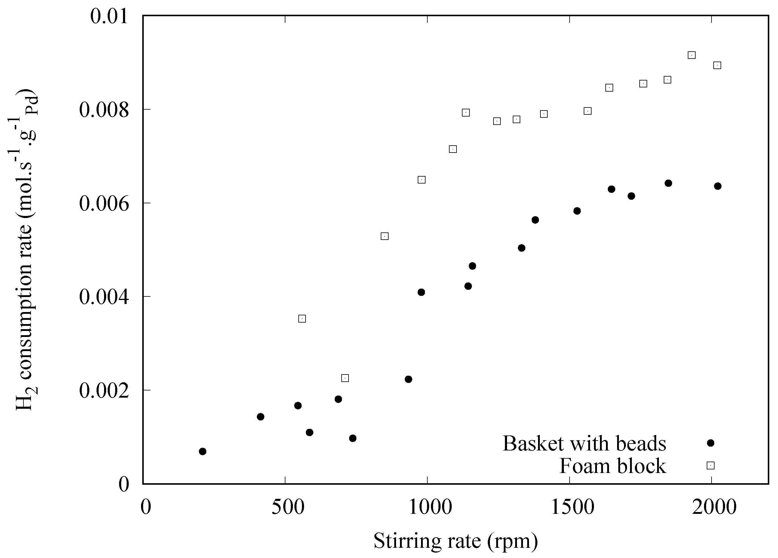
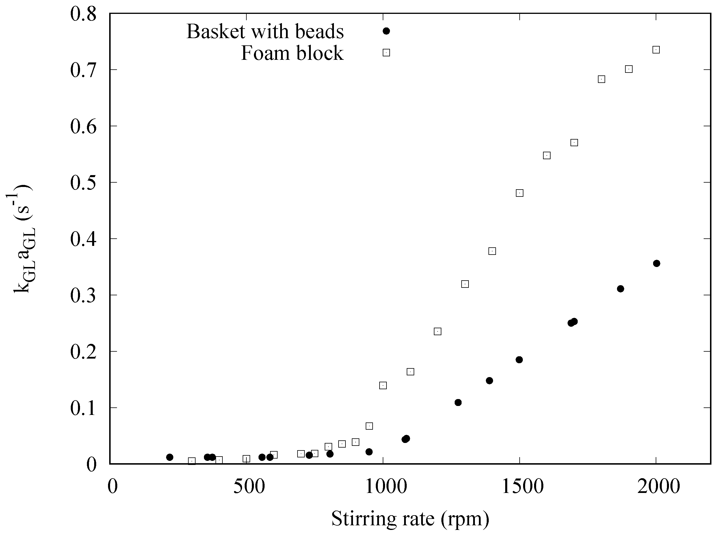
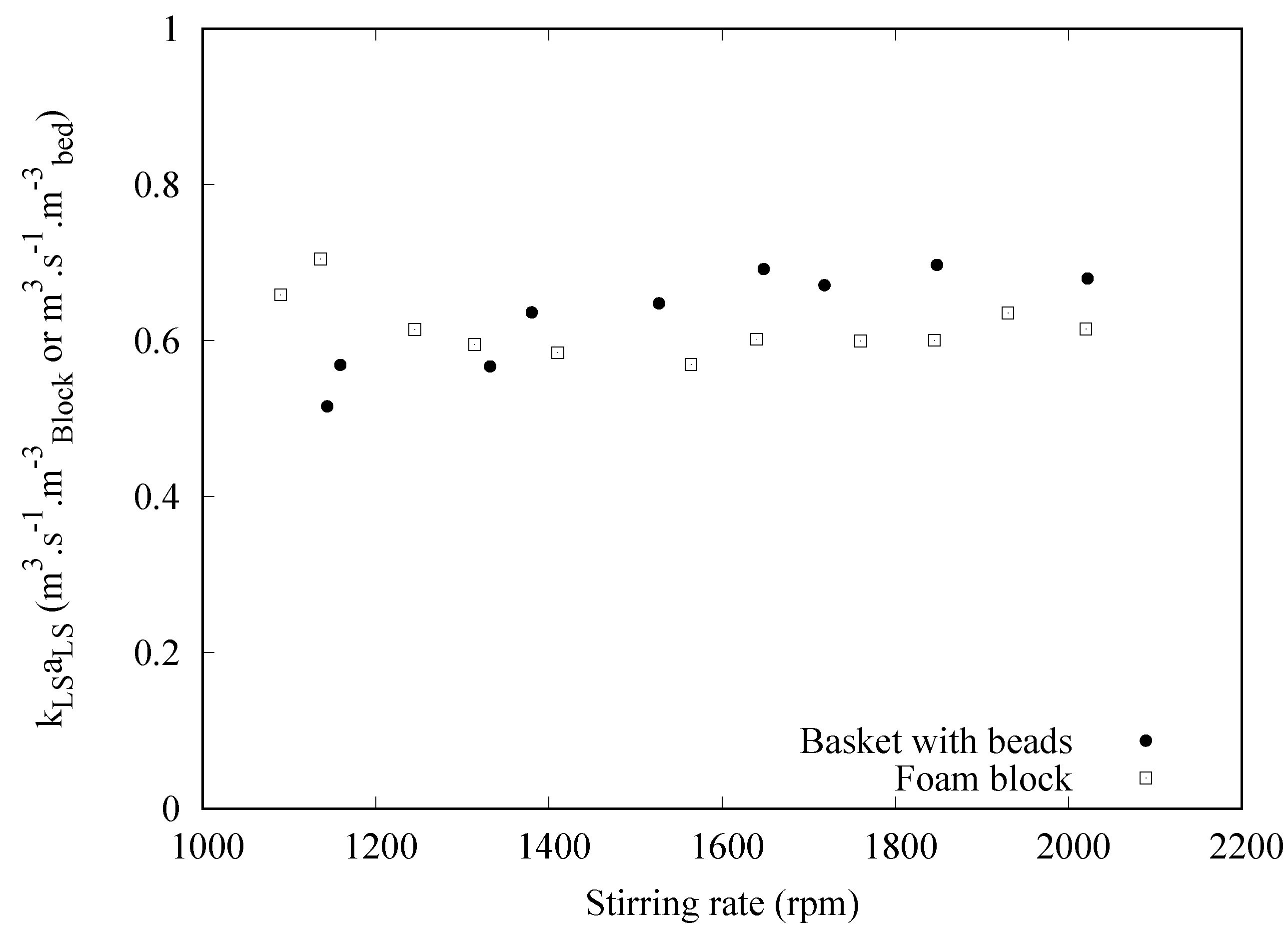
3. Results and Discussion

The performances of the beads-filled basket and the foam block in terms of chemical productivity were assessed by measuring the apparent rates of hydrogen consumption during the hydrogenation of α -methylstyrene on P d / A l 2 O 3 catalyst. Both systems were compared at a wide range of stirring speeds (300–2000 rpm). As seen in Figure 3, the hydrogen consumption rates increase with stirring speeds and were much higher for the coated foam than for the beads-filled basket for the whole range of stirring rates. Note that the hydrogen consumption rate never reaches a plateau, indicating that the reaction is strongly limited by mass transfer (either GL and/or LS) in the whole range of stirring speeds.
Figure 4 shows the k G L a G L coefficients vs. stirring rate for the foam block and the beads-filled basket. This curve is a typical one for a gas inducing impeller. Below the critical stirring speed Nc (which was around 800–900 rpm in this case), the stirring power was too low to generate a depression necessary to cause gas flowing from the gas bulk to the liquid bottom. Above Nc, the gas flowed through a hollow shaft, inducing gas bubbles. The k G L a G L coefficients were found to be much higher in the case of the foam block. Note that it was checked that very similar results were obtained with a five-foam stack (11 mm each) than with a 55 mm high block. To try to explain the difference foam vs. beads, we compared the basket grid size with the foam cell size. The mean mesh size of the basket was about 800 μ m, which was equivalent to the mean pore diameter of the 40 PPI foam. However, the porosities of the foam Block and the basket bed were 0.91 and 0.46, respectively. Thus, assuming a uniform porosity in each direction, the cross-sectional area for flow is twice as high for the foam than for the packed bed. Consequently, we could conclude that the GL mass transfer was strongly enhanced by foam configuration, compared to the basket configuration. Thanks to the possibility to work at a high stirring rate, GL mass transfer can also reach much higher values than what was obtained with rotating stirring foams [10].
The hydrogenation of α -methylstyrene was performed under experimental conditions ensuring mass transfer limitation. The k L S was calculated from Equation (3) using the k G L a G L obtained previously. The LS coefficients ( k L S a L S ) are presented in Figure 5. Note that the results are only presented for stirring rates above 1000 rpm: below the critical value of stirring rate and close to it, the GL mass transfer is too low and the estimation uncertainty is too high to provide accurate values of k L S .
The Lévêque equation [20] gives a relationship between heat transfer and pressure drop in a tube. Following the analogy between mass and heat transfers at a solid interface, the Sherwood number is also an increasing function of the Lévêque number, which itself is proportional to the friction factor and thus to the pressure drop. Thus, finding similar k L S a L S in the basket and in the 40 PPI foam stack may be due to similar radial pressure drops in both systems. The pressure drop through the foam is expected to be lower than that through the basket. Two hypotheses can be proposed to explain these apparent contradictions. First, the radial porosity in the beads-filled basket may not correspond to the mean porosity of the bed and may be smaller. Indeed, the gap between the inner and the outer basket walls is only 8.5 mm, corresponding to a maximum of three (non-compacted) beads; it could lead to a smaller pressure drop than expected. A second argument is that the k L S values come from an indirect determination and an error bar should be considered.

4. Conclusions

We have reported the use of a new GLS (Gas-Liquid-Solid) reactor using a stationary foam coated with a catalyst layer. The chosen geometry was appropriate to a fair comparison with a traditional basket reactor filled with 2.5 mm beads. Thanks to a higher porosity, the GL mass transfer was twice as high in the foam configuration than in the basket one, demonstrating the interest in using such new configuration. We have successfully experienced the use of this reactor for kinetic measurements [21,22]. Moreover, as this configuration is very flexible, the reactor can be used with a variable height of foam, different foam porosities, etc. The effect of these parameters on GL and LS mass transfers will be studied in a future publication.

Author Contributions

N.B., D.A. and L.J. performed the experiments, M.-L.Z characterized the foams (image analysis), V.M. and F.B. conceived the foam set-up, F.S.-L, L.V. and I.P. analysed the data, V.M. and I.P. wrote the paper.

Funding

This research received no external funding.

Acknowledgments

CNRS, CPE Lyon and UCBL are acknowledged for their financial support.

Conflicts of Interest

The authors declare no conflict of interest.

Abbreviations

The following abbreviations are used in this manuscript:
a G L Specific area of gas–liquid interface (m 1 )
a L S Specific area of liquid–solid interface (m 2 · m B l o c k 3 ) or (m 2 · m b e d 3 )
C L H 2 Concentration of hydrogen solved in liquid phase (mol · m L 3 )
C L H 2 * Concentration of hydrogen solved in liquid phase at saturation (equilibrium) (mol · m L 3 )
C S H 2 Concentration of hydrogen solved in liquid phase at solid interface (mol · m L 3 )
d p Particle diameter (m)
D m Diffusivity of α -methylstyrene in methylcyclohexane (m 2 · s 1 )
E a Activation energy of reaction (J · mol 1 )
k c i n Kinetic parameter of reaction (m 3 · s 1 · kg C a t a l y s t 1 )
k G L Gas–liquid mass transfer coefficient (m · s 1 )
K H Adsorption equilibrium constant of hydrogen (m 3 · mol 1 )
k L S Liquid–solid mass transfer coefficient (m · s 1 )
k 0 Pre-exponential kinetic parameter of reaction (mol · s 1 · kg P d 1 )
n H 2 R e s e r v o i r Number of moles of hydrogen in the reservoir (mol)
n L H 2 Number of moles of hydrogen in the liquid phase (mol)
NStirring speed (rpm)
N c Critical Stirring Speed (rpm)
PInstantaneous pressure of hydrogen (bar)
P f Stabilized pressure of hydrogen (bar)
P H 2 R e s e r v o i r Hydrogen pressure in the reservoir (bar)
P m Maximal pressure of hydrogen (bar)
P 0 Initial pressure of hydrogen (bar)
P P I Pores per inch
r R Reaction rate of hydrogenation of α -methylstyrene (mol · s 1 · m L 3 )
RPerfect Gas constant (J · mol 1 · K 1 )
S h Sherwood number (-), S h = k L S d p D m
tTime (s)
TTemperature (K)
T R e s e r v o i r Temperature in the reservoir (K)
V L Volume of liquid (m L 3 )
V R e s e r v o i r Volume of reservoir (m 3 )
WMass of catalyst (kg)
x P d Mass fraction of palladium atoms in the alumina (-)
ϵ S Volume fraction of foam block or of catalytic bed in the liquid bulk (m B l o c k 3 · m L 3 ) or (m b e d 3 · m L 3 )
η Efficiency factor (-)

References

  1. Chaudhari, R.V.; Mills, P.L. Multiphase catalysis and reaction engineering for emerging pharmaceutical processes. Chem. Eng. Sci. 2004, 59, 5337–5344. [Google Scholar] [CrossRef]
  2. Porta, R.; Benaglia, M.; Puglisi, A. Flow Chemistry: Recent Developments in the Synthesis of Pharmaceutical Products. Org. Process. Res. Dev. 2016, 20, 2–25. [Google Scholar] [CrossRef]
  3. Le Doan, T.V.; Stavarek, P.; de Bellefon, C. A Method to Identify Best Available Technologies (BAT) for Hydrogenation Reactors in the Pharmaceutical Industry. J. Flow Chem. 2012, 2, 77–82. [Google Scholar] [CrossRef] [Green Version]
  4. Robinson, K.K.; Mahoney, J.A. Gradientless Reactors for Process Kinetic Studies and Catalyst Testing. Abst. P. Am. Chem. Soc. 1977, 174, 15–16. [Google Scholar]
  5. Pitault, I.; Fongarland, P.; Koepke, D.; Mitrovic, M.; Ronze, D.; Forissier, M. Gas–liquid and liquid–solid mass transfers in two types of stationary catalytic basket laboratory reactor. Chem. Eng. Sci. 2005, 60, 6240–6253. [Google Scholar] [CrossRef]
  6. Mitrovic, M.; Pitault, I.; Forissier, M.; Simoens, S.; Ronze, D. Liquid–Solid Mass Transfer in a Three-Phase Stationary Catalytic Basket Reactor. AIChE J. 2005, 51, 1747–1757. [Google Scholar] [CrossRef]
  7. Visscher, F.; van der Schaaf, J.; Nijhuis, T.; Schouten, J. Rotating reactors—A review. Chem. Eng. Res. Des. 2013, 91, 1923–1940. [Google Scholar] [CrossRef]
  8. Leon, M.A.; Tschentscher, R.; Nijhuis, T.A.; van der Schaaf, J.; Schouten, J.C. Rotating Foam Stirrer Reactor: Effect of Catalyst Coating Characteristics on Reactor Performance. Ind. Eng. Chem. Res. 2011, 50, 3184–3193. [Google Scholar] [CrossRef]
  9. Leon, M.; Geers, P.; Nijhuis, T.; van der Schaaf, J.; Schouten, J. Effect of foam stirrer design on the catalytic performance of rotating foam stirrer reactors. Chem. Eng. J. 2012, 207–208, 209–217. [Google Scholar] [CrossRef]
  10. Leon, M.; Maas, R.; Bieberle, A.; Schubert, M.; Nijhuis, T.; van der Schaaf, J.; Hampel, U.; Schouten, J. Hydrodynamics and gas–liquid mass transfer in a horizontal rotating foam stirrer reactor. Chem. Eng. J. 2013, 217, 10–21. [Google Scholar] [CrossRef]
  11. Teshima, H.; Ohashi, Y. Particle to Liquid Mass Transfer in a Rotating Catalyst Basket Reactor. Chem. Eng. J. Jpn. 1977, 10, 70–72. [Google Scholar] [CrossRef]
  12. Goto, S.; Saito, T. Liquid–solid mass transfer in basket type three-phase reactors. Chem. Eng. J. Jpn. 1984, 17, 324–327. [Google Scholar] [CrossRef]
  13. Pitault, I.; Fongarland, P.; Mitrovic, M.; Ronze, D.; Forissier, M. Choice of laboratory scale reactors for HDT kinetic studies or catalyst tests. Catal. Today 2004, 98, 31–42. [Google Scholar] [CrossRef]
  14. Braga, M. Study of External Transport Phenomena and Hydrodynamics in a Stirred Catalytic Basket Reactor. Ph.D. Thesis, University of Lyon, Lyon, France, 2014. [Google Scholar]
  15. Tourvieille, J.N.; Philippe, R.; de Bellefon, C. Milli-channel with metal foams under an applied gas–liquid periodic flow: External mass transfer performance and pressure drop. Chem. Eng. J. 2015, 267, 332–346. [Google Scholar] [CrossRef]
  16. Dietrich, E.; Mathieu, C.; Delmas, H.; Jenck, J. Raney-nickel catalyzed hydrogenations: gas–liquid mass transfer in gas-induced stirred slurry reactors. Chem. Eng. Sci. 1992, 47, 3597–3604. [Google Scholar] [CrossRef]
  17. Johnson, D.L.; Saito, H.; Polejes, J.D.; Hougen, O.A. Effects of bubbling and stirring on mass transfer coefficients in liquids. AIChE J. 1957, 3, 411–417. [Google Scholar] [CrossRef]
  18. Meille, V.; de Bellefon, C. Effect of water on alpha-methylstyrene hydrogenation on Pd/Al2O3. Can. J. Chem. Eng. 2004, 82, 190–193. [Google Scholar] [CrossRef]
  19. Meille, V.; de Bellefon, C.; Schweich, D. Kinetics of α-Methylstyrene Hydrogenation on Pd/Al2O3. Ind. Eng. Chem. Res. 2002, 41, 1711–1715. [Google Scholar] [CrossRef]
  20. Martin, H. The generalized Lévêque equation and its practical use for the prediction of heat and mass transfer rates from pressure drop. Chem. Eng. Sci. 2002, 57, 3217–3223. [Google Scholar] [CrossRef]
  21. Simescu-Lazar, F.; Meille, V.; Bornette, F.; Campoli, F.; de Bellefon, C. In situ electrochemical regeneration of deactivated coated catalyst on basket foam in Robinson-Mahoney reactor: Example of Pd/C for nitrobenzene hydrogenation. Catal. Today 2015, 249, 52–58. [Google Scholar] [CrossRef]
  22. Simescu-Lazar, F.; Chaieb, T.; Pallier, S.; Veyre, L.; Philippe, R.; Meille, V. Direct coating of carbon-supported atalysts on monoliths and foams—Singular behaviour of Pd/MWCNT. Appl. Catal. A Gen. 2015, 508, 45–51. [Google Scholar] [CrossRef]
Figure 1. Experimental device. From left to right: gas-inducing impeller, basket, and foam block.
Processes 06 00117 g001
Figure 2. Schematic representation of the catalytic zone in the beads and in the foam stack.
Processes 06 00117 g002
Figure 3. Hydrogen consumption rate per gram of Pd in α -methylstyrene hydrogenation—comparison between the basket with 2 mm beads and the 40 PPI (pores per inch) foam block.
Processes 06 00117 g003
Figure 4. GL (Gas–liquid) mass transfer—comparison between the basket with 2 mm beads and the 40 PPI foam block.
Processes 06 00117 g004
Figure 5. LS (Liquid–solid) mass transfer—comparison between the basket with 2 mm beads and the 40 PPI foam block.
Processes 06 00117 g005

